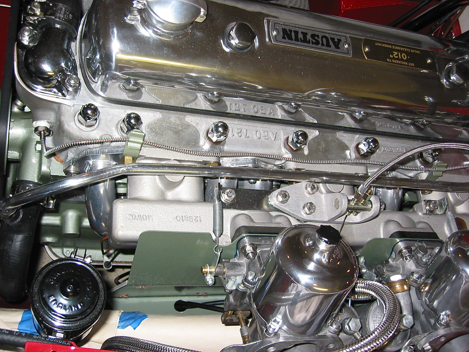
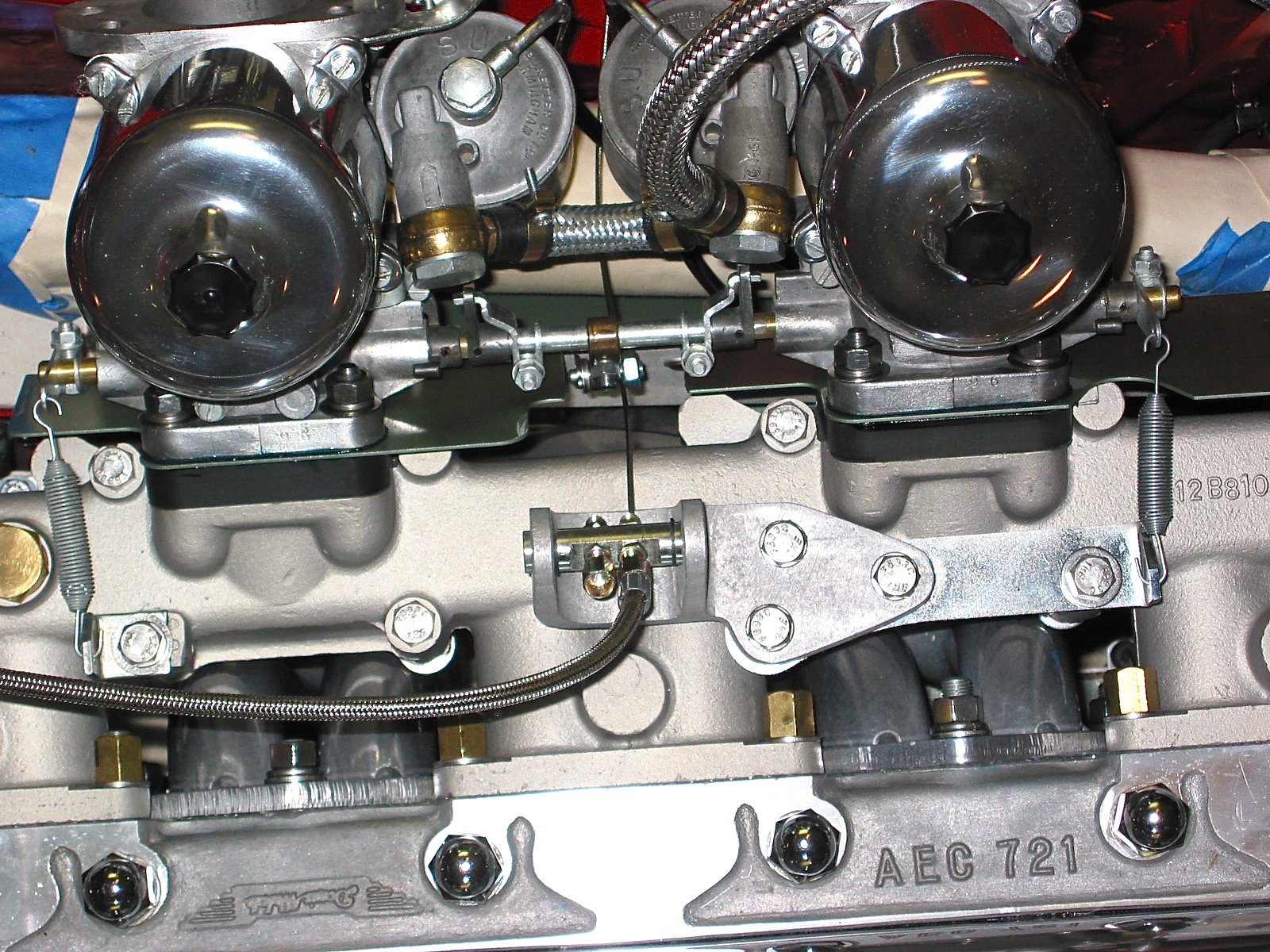
I continued with the assembly of various engine components in the forty-fifth week of restoration. I learned the hard way that the vacuum line from the intake manifold to the distributor needs to be one of the first items to install on the engine, not one of the last! However, after a number of trial fittings I did manage to get the pipe installed with only having to disconnect a few hoses. The copper pipe slips into rubber connector fittings at the manifold and distributor.
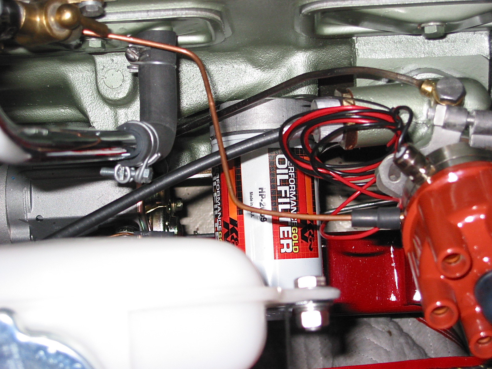
Vacuum Pipe RH side to distributor
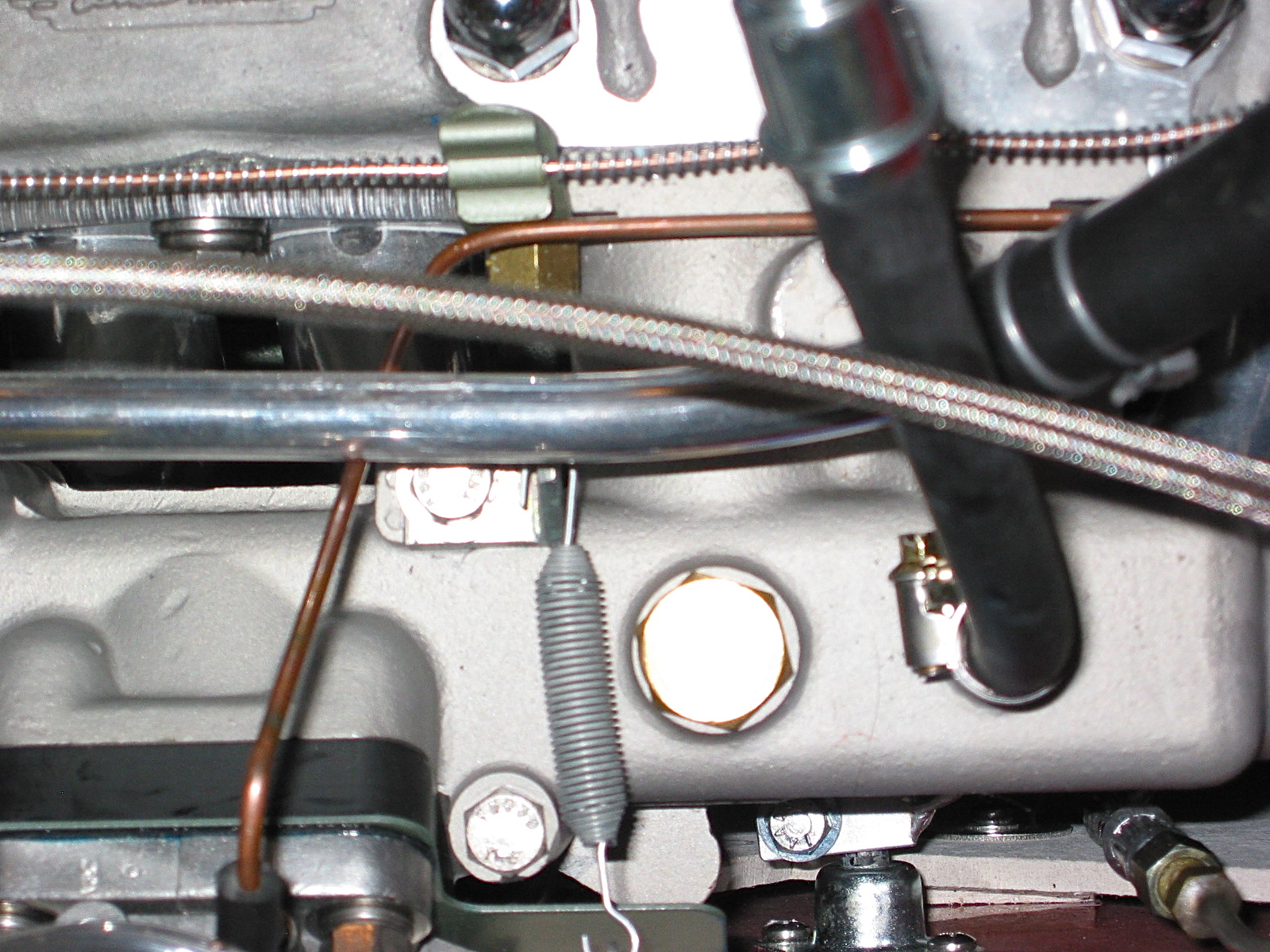
Vacuum Pipe LH side to rear carb
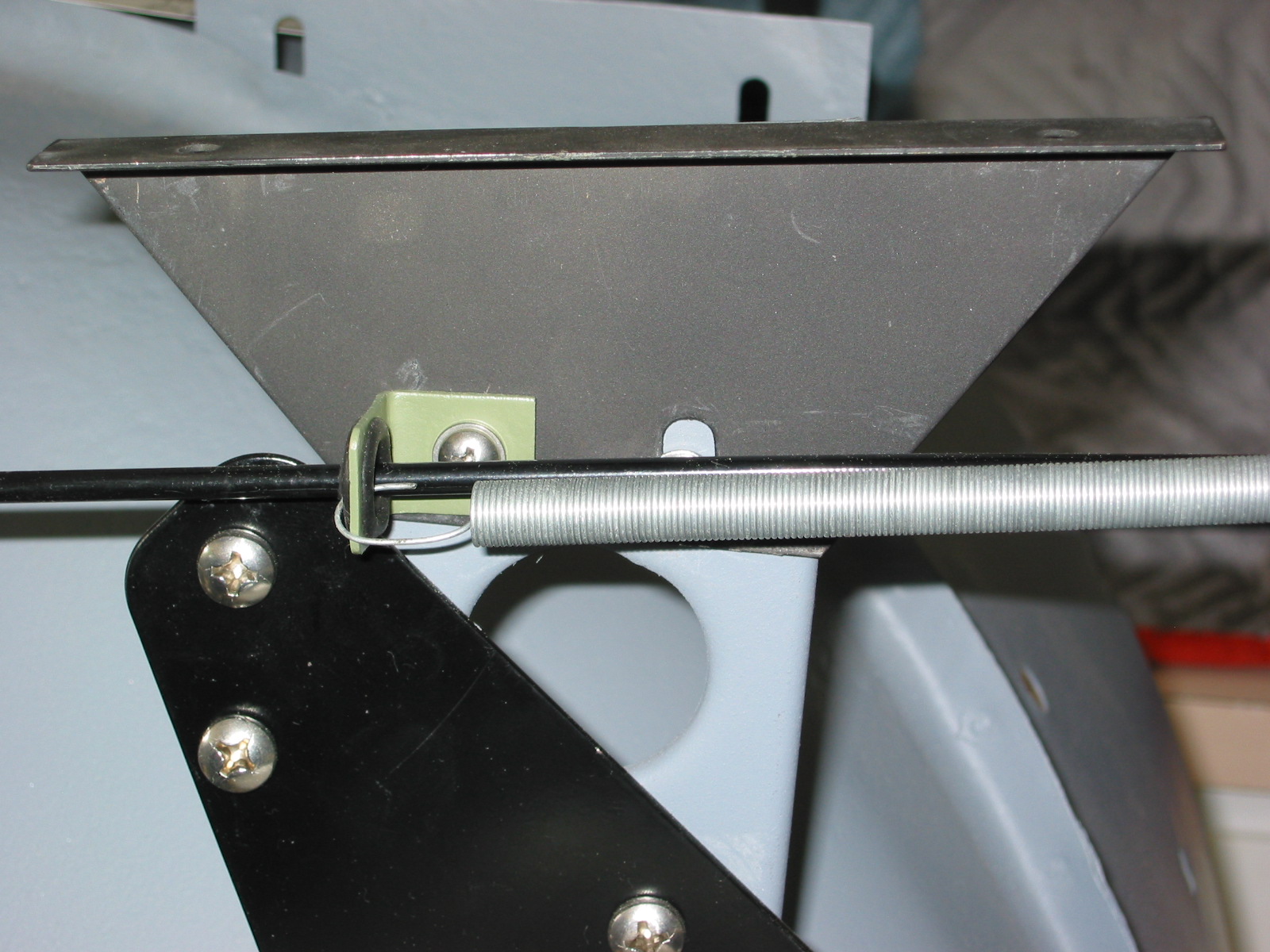
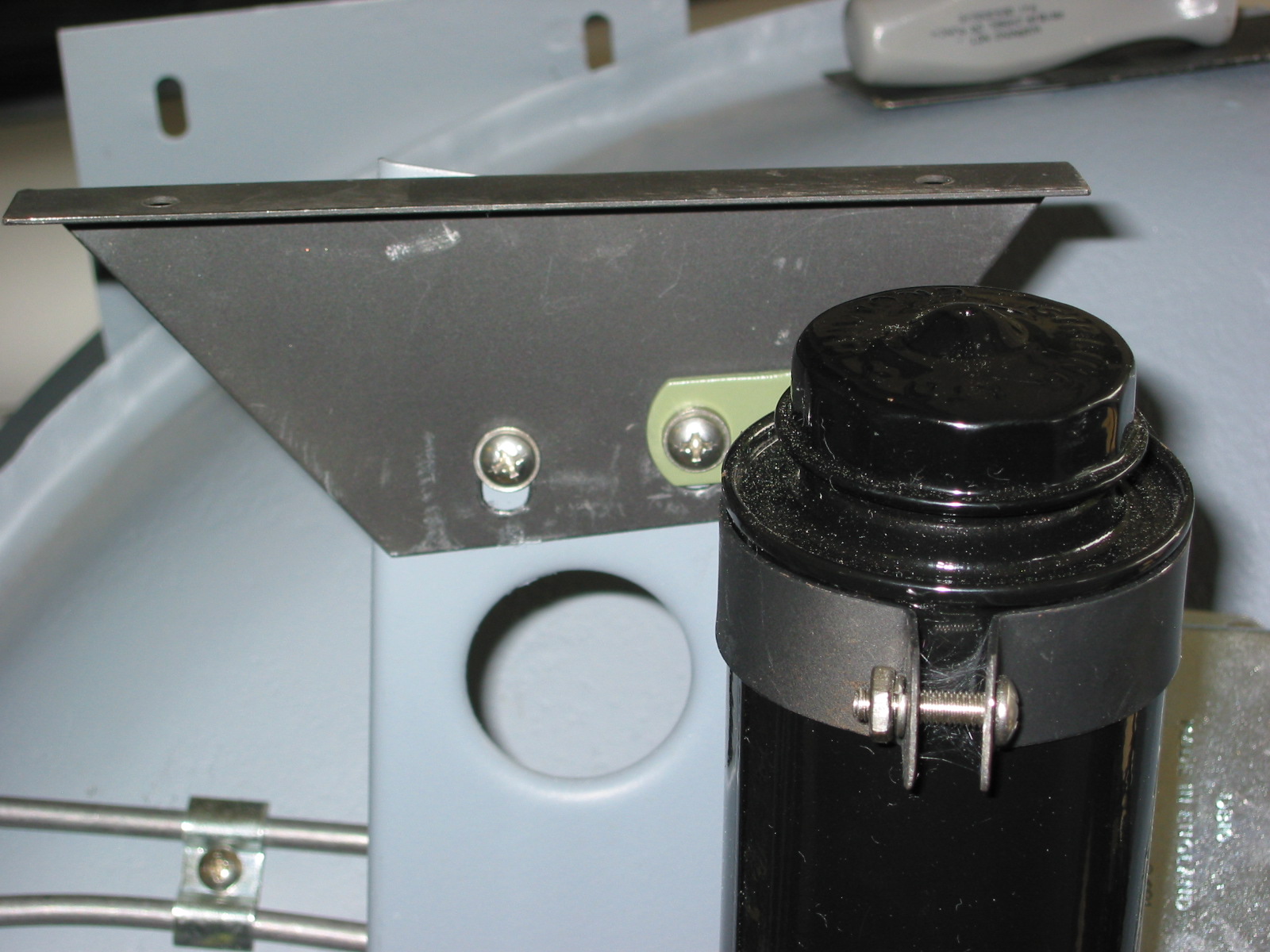
The capillary tube running from the water temperature/oil pressure gauge to the fitting on the LH front of the cylinder head was the next item to install. Two small mounting clips and brackets were first mounted to head bolts securing the intake manifold and the tube was slipped under the clips, and the temperature sensing bulb inserted into the head and screwed home.
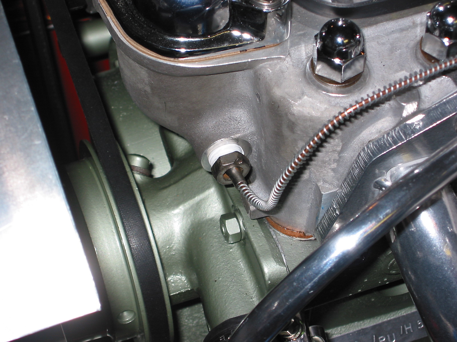
Capillary tube mounting
Given all of the typical concerns about overheating with the Healey engine, I decided to use a six blade aluminum fan sourced from British Car Specialists, The fan comes with an aluminum spacer to fit between the water pump pulley and the fan.
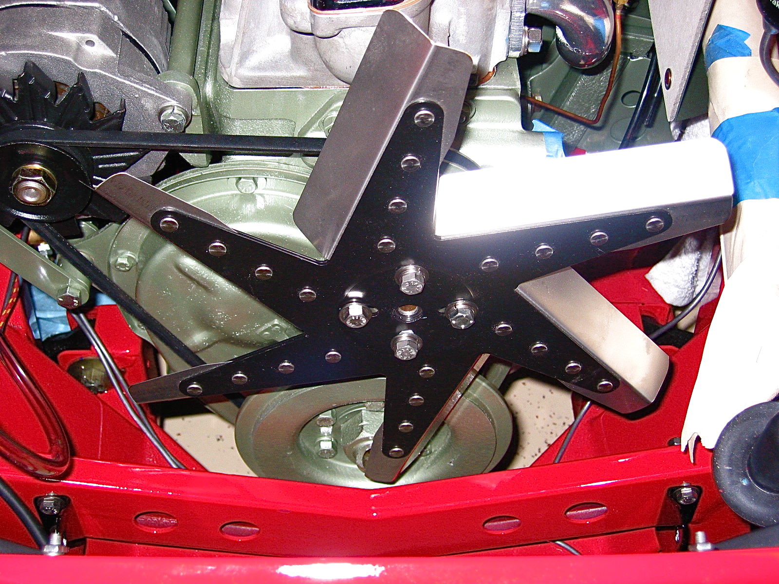
Stainless Flex Fan
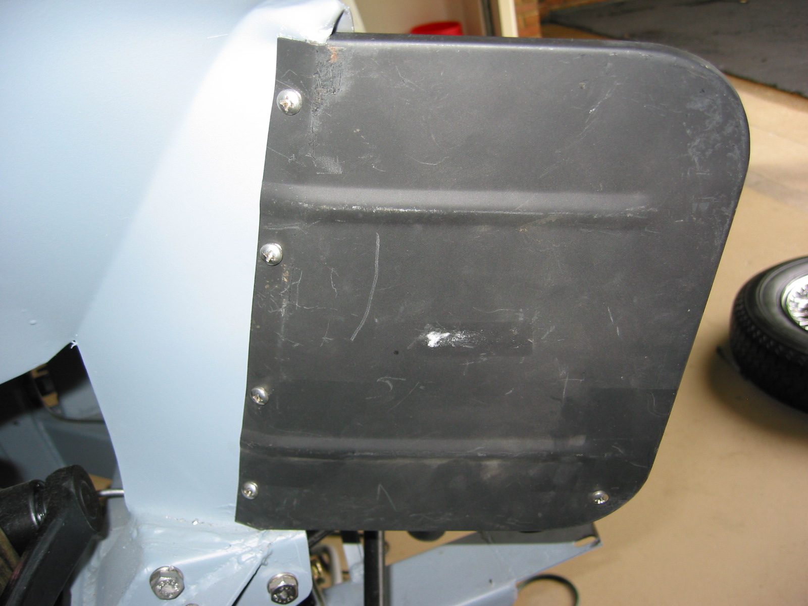
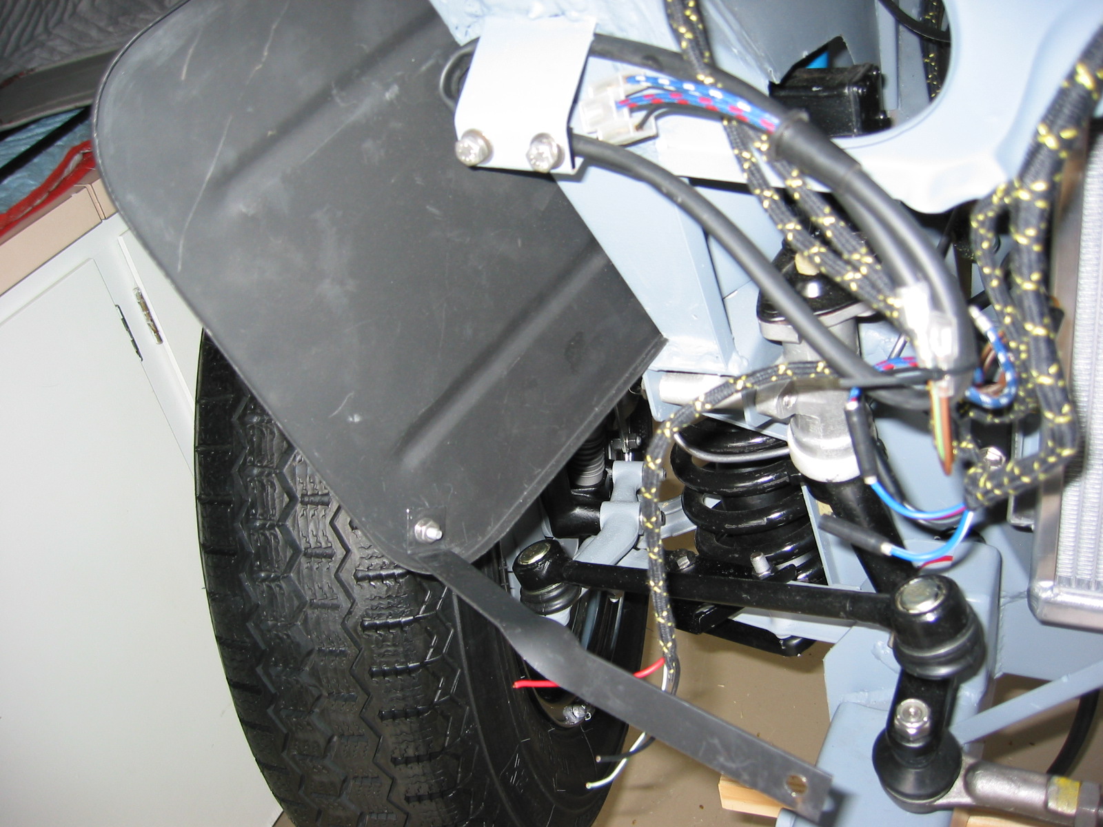
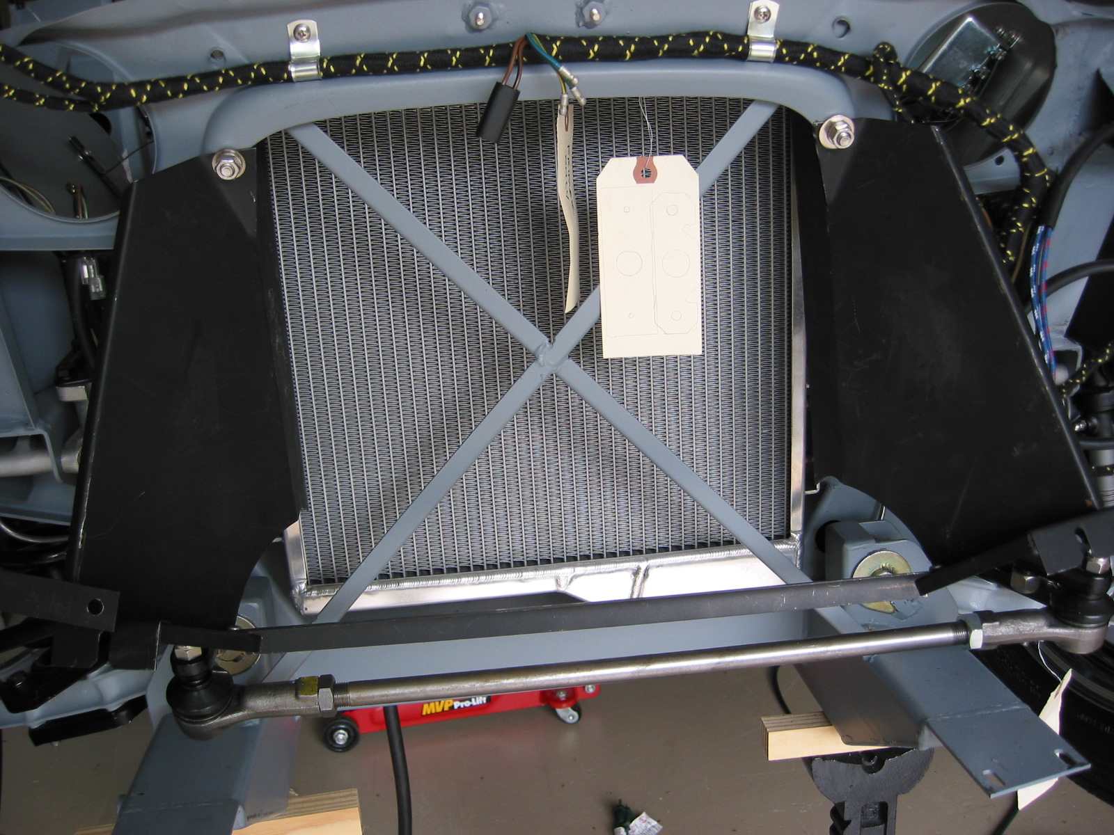
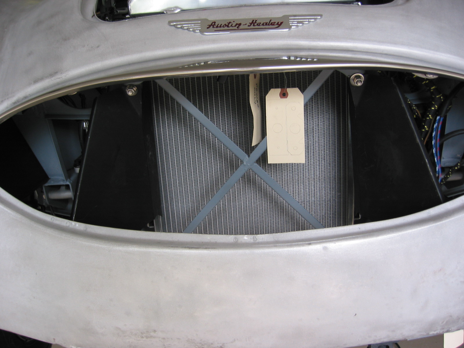
The aluminum radiator and custom made air deflectors were the next pieces to go on. The radiator was ordered from Cape International and I must say that the craftsmanship is superb. The aluminum deflectors I had made caused the radiator to be a tight fit, but with patience all components were secured into place. I put a light coat of black radiator paint on the front surface of the radiator to give a standard appearance when looking through the front grille. I am using a 7 lb radiator cap as was standard with the original radiator. I then attached the overflow tank hose as well as the lower and upper hoses to the head and the water pump.
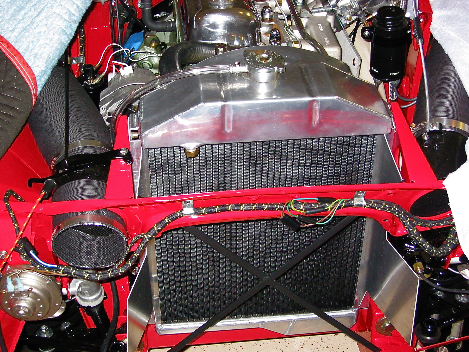
Aluminum Radiator and Baffles

Aluminum Radiator and Baffles
Radiator Hose Top
I replaced the original copper hot water pipe with a polished aluminum pipe simply for aesthetic reasons. I like the look.
Aluminum Heater Pipe
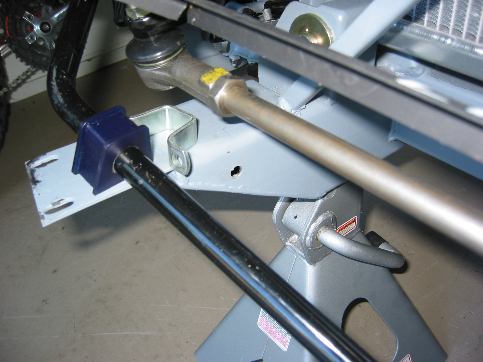
Denis Welch makes a high quality (read, as expensive) throttle cable mounting bracket for a conversion from the original mechanical linkage. I did not use the complete Welch kit but I did use the piece located on the intake manifold. It is a well engineered design and looks like it belongs there. I incorporated a stainless steel sheathed throttle cable from Lokar. Fellow enthusiast Jack Brashear gave me some help on the optimal design for the accelerator pedal lever to which the cable is attached. I lengthened an original BJ8 lever to get the desired result. I previously installed the firewall bracket for the cable assembly.
Throttle Cable Bracket
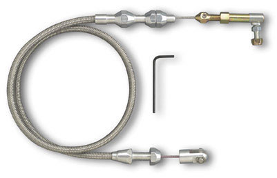
Lokar Throttle cable
In my restoration, I converted to a BJ8 intake manifold and HD8 2” carburetters. This, of course, meant adding a dual choke mechanism as used on the BJ8s. The parts were sourced from Moss Motors. The choke bracket that converts the single cable from the dashboard fascia to the dual cables running to each of the carbs was mounted to the firewall and choke cables were connected. A small block provides the linkage for the single to dual cable. I drilled and tapped the ends of the remote control choke block for #6 set screws to ensure the proper return of the cables in the bracket since this is a common problem with HD8 carbs.

Choke assembly
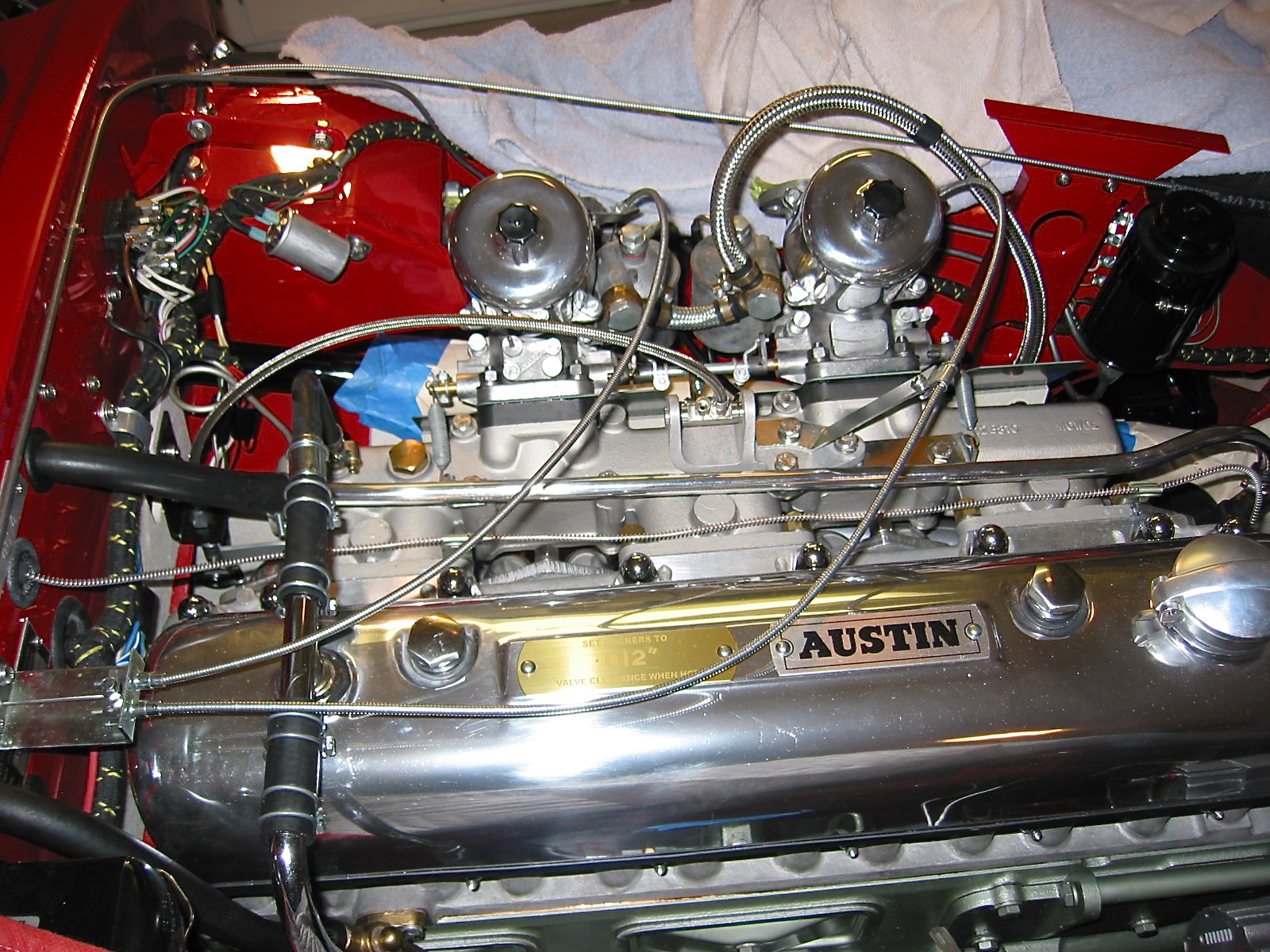
Choke Assembly 2
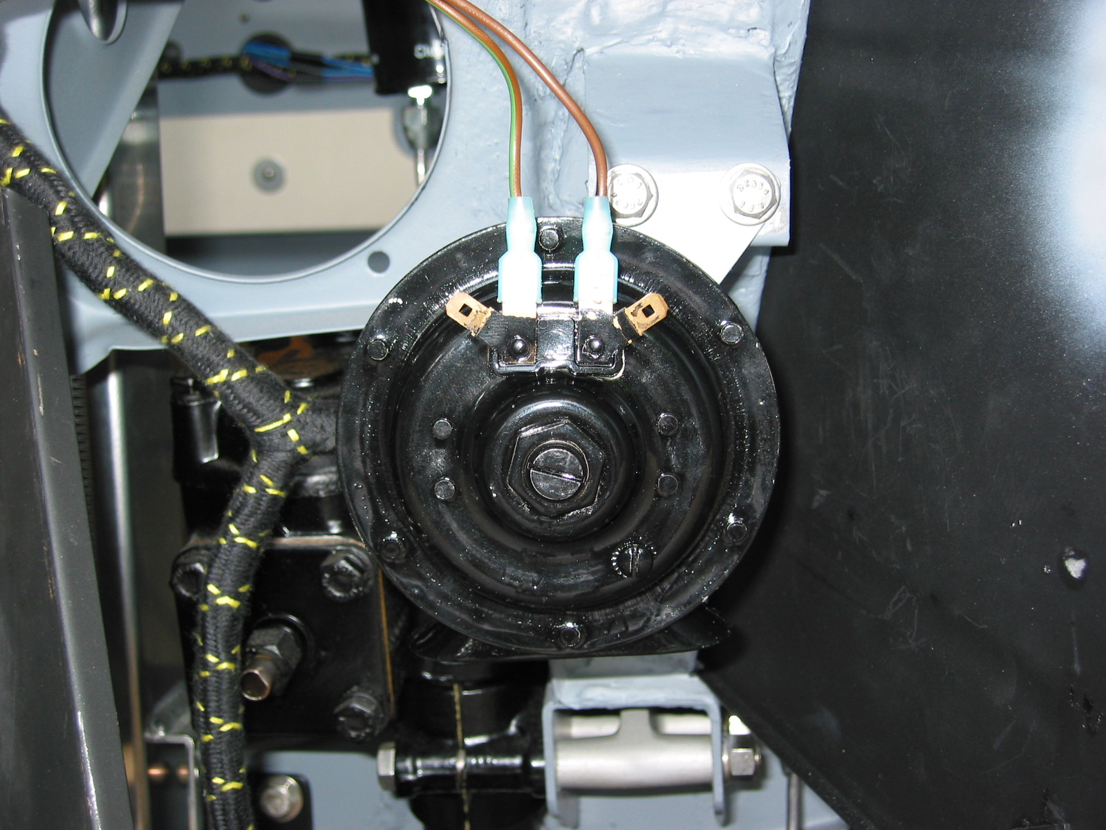
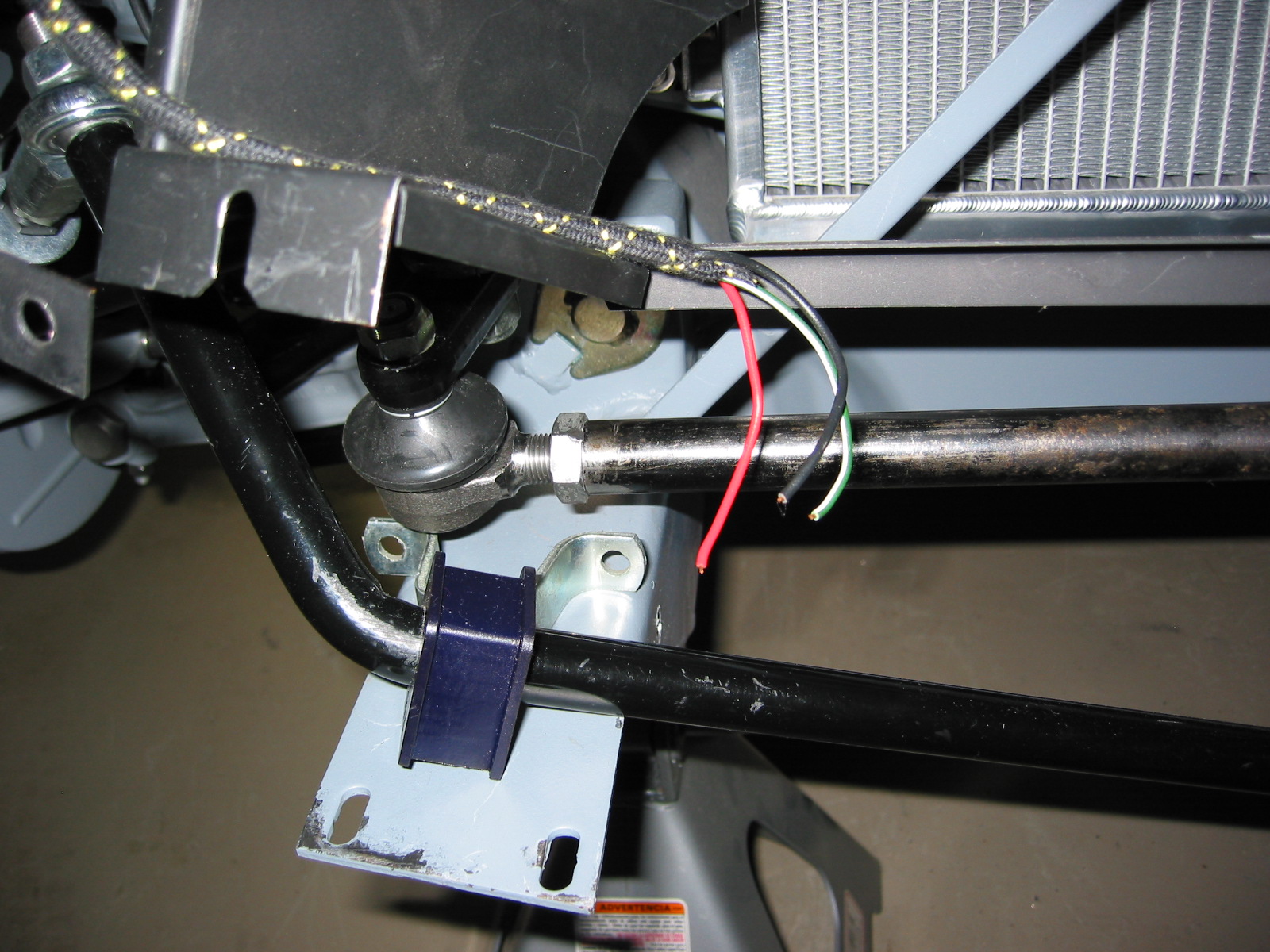
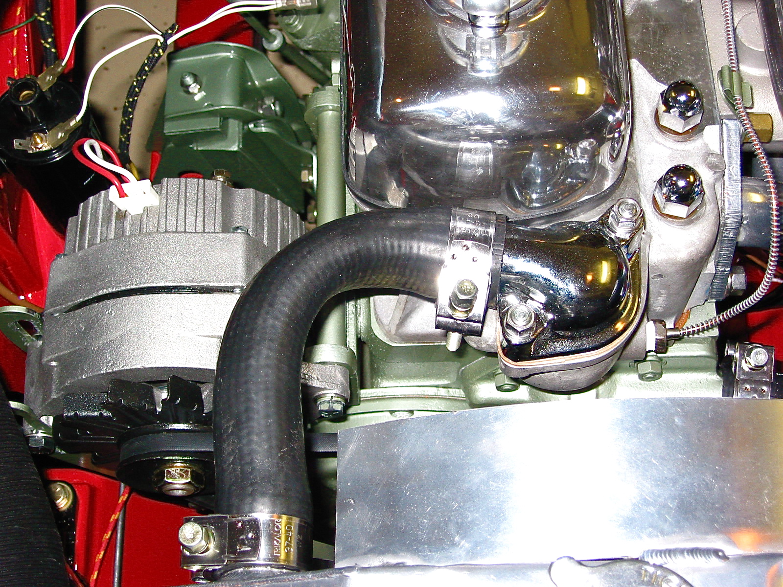
Although Jack at Coachworks had installed the alternator with the engine rebuild, I had to remove it for the engine installation. I then put it back on the engine and wired it. Hendrix Wire Wheel provided photos and a wiring diagram to make this an easy job. The red wire on the alternator plug serves as a jumper to the screw terminal on the back of the alternator. The white wire on the plug was connected to the large yellow wire emerging from the wiring harness, originally intended for the large spade connection on the dynamo. The yellow/green wire originally connected to the dynamo was no longer required. Because the alternator output is more substantial than the dynamo, I elected to use a much heavier wire from British Wiring to run from the battery side of the starter solenoid to the screw post on the back of the alternator.
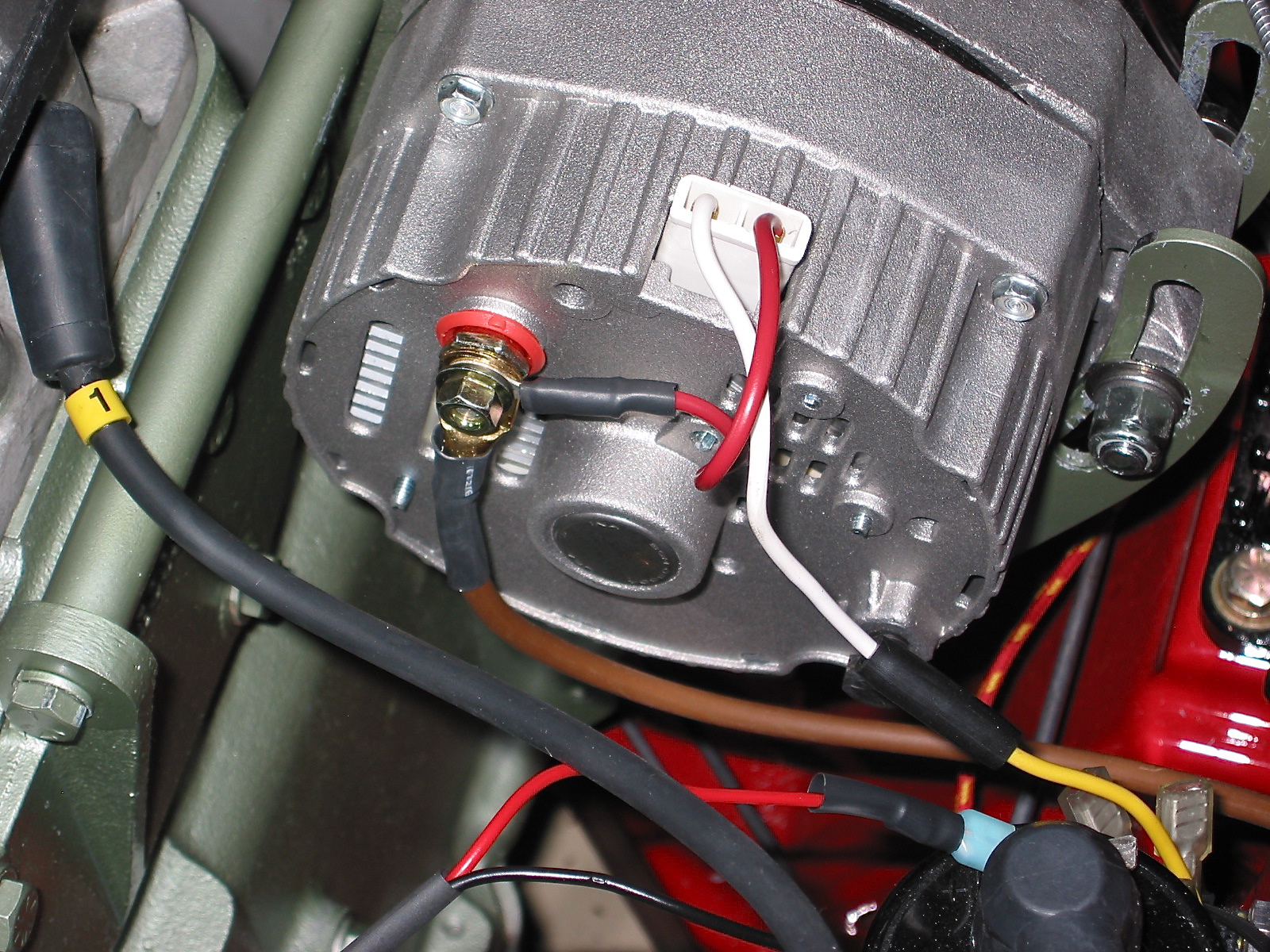
Alternator wiring
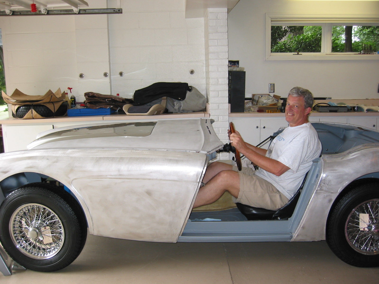
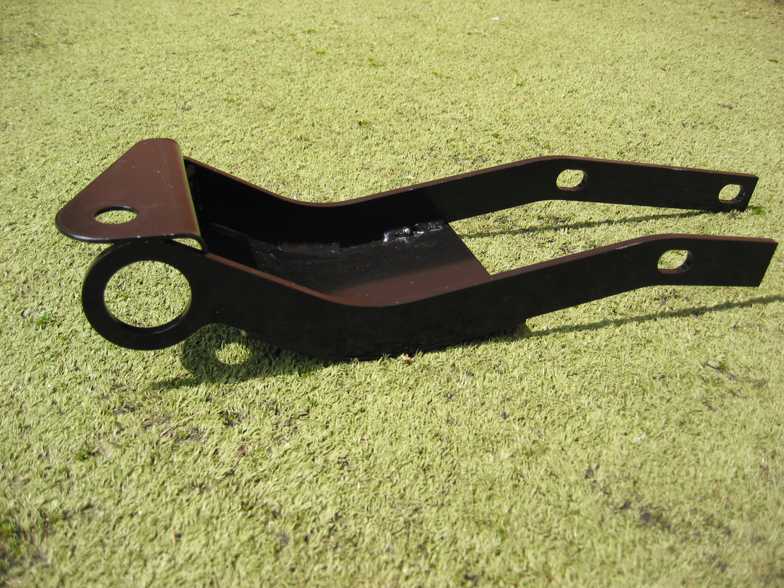
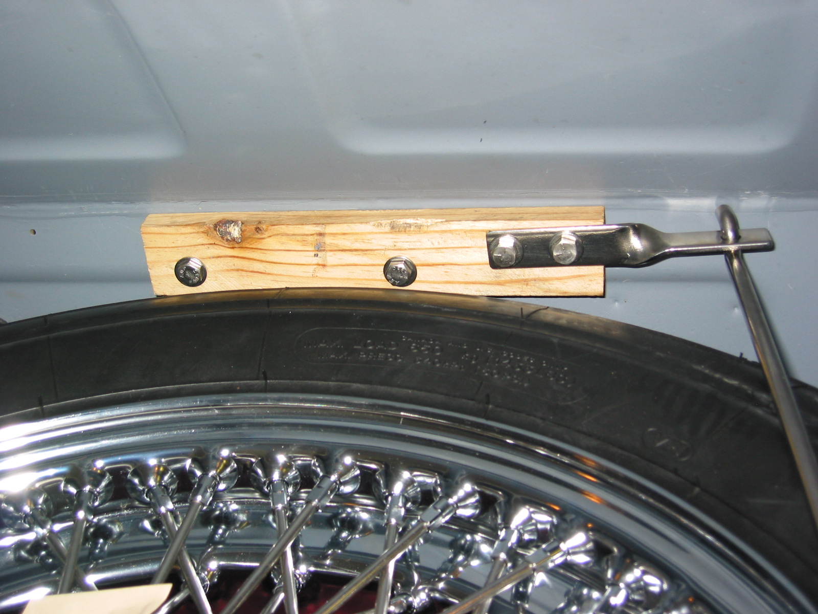
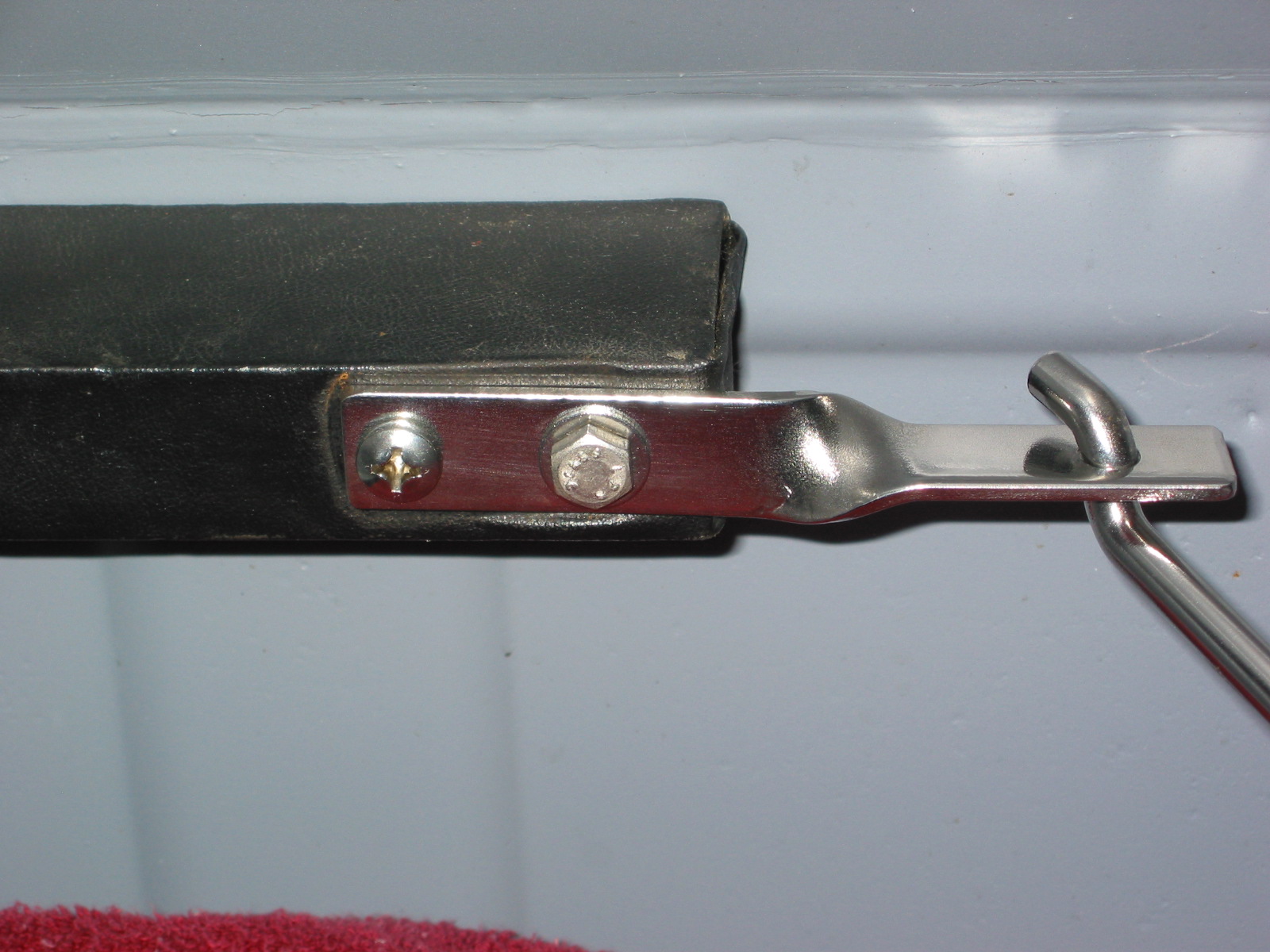
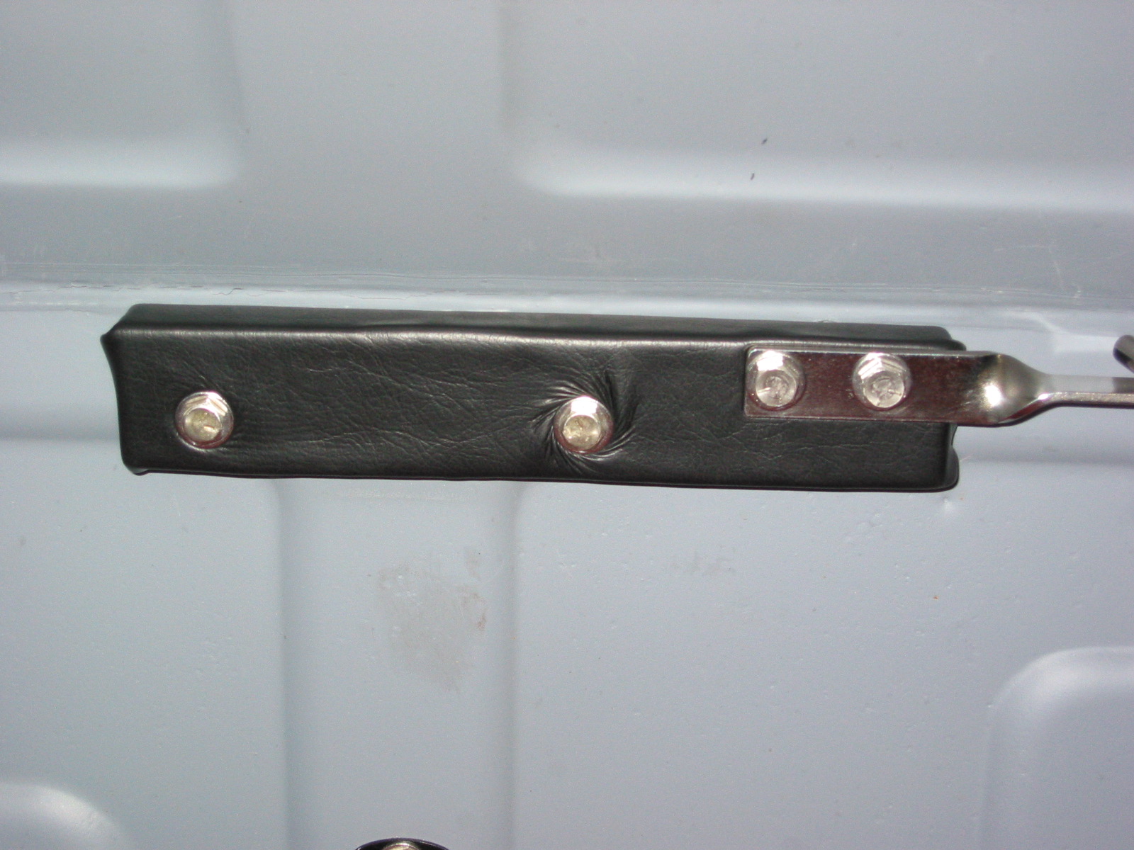
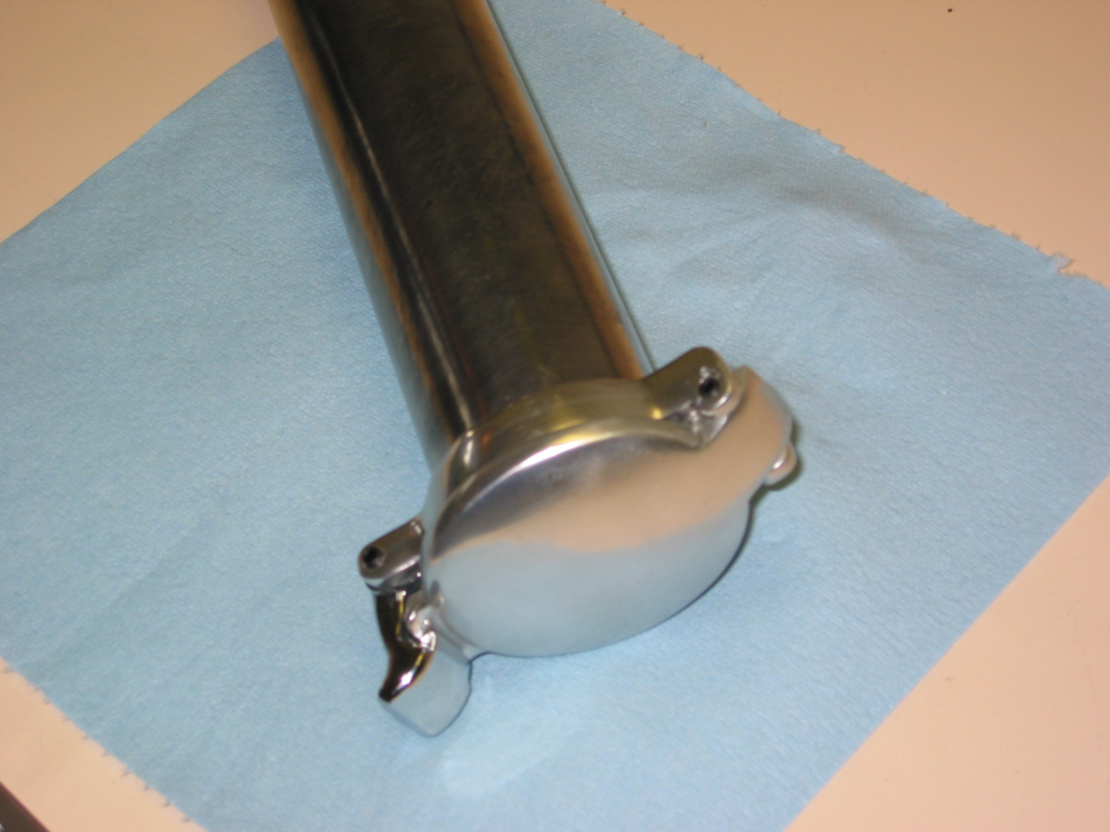
The final job of the week was installing the bonnet latch assembly to the car. I waited until the engine was in the car so that it would not impede the path of the engine as it was seated in the vehicle.
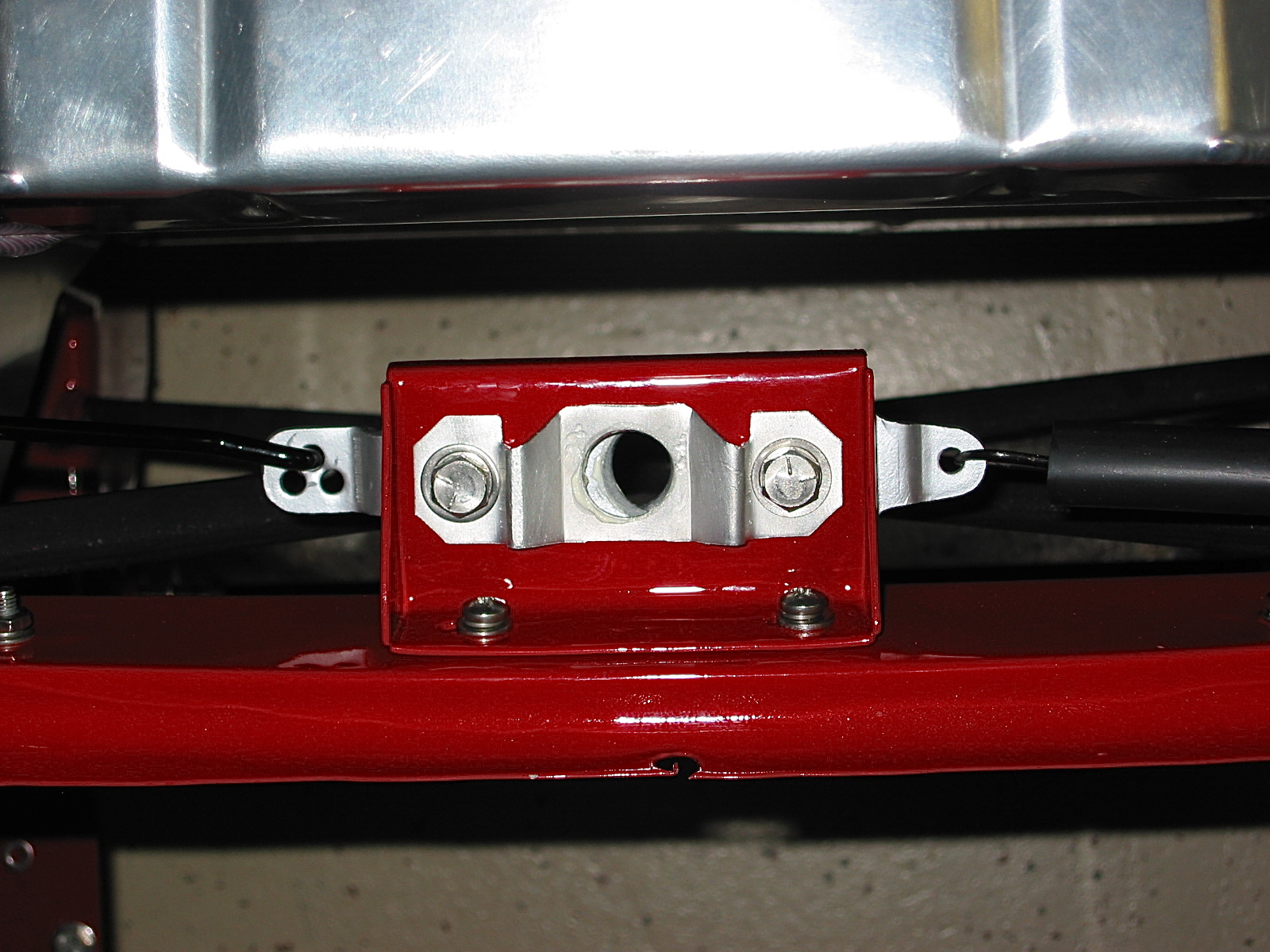
Bonnet Latch Assembly