June 29, 2002
Final Interior Dismantling
Gearbox tunnel and extension cover. Both were rusted badly and were discarded. I learned later as I was fitting new parts that I should not have violated the restorer’s rule: Never throw anything away until the project is complete!

Gearbox tunnel and extension cover
Fresh Air cover plate and screen on left (driver’s) side. Three self threading screws.
Parcel tray on passenger side. Four self tapping screws on the firewall. Three self tapping screws on the right side wall. One screw and nut into left side to hanging support bar. Then removed the parcel support bar with one screw and nut at top.
Parcel Tray Support brace.
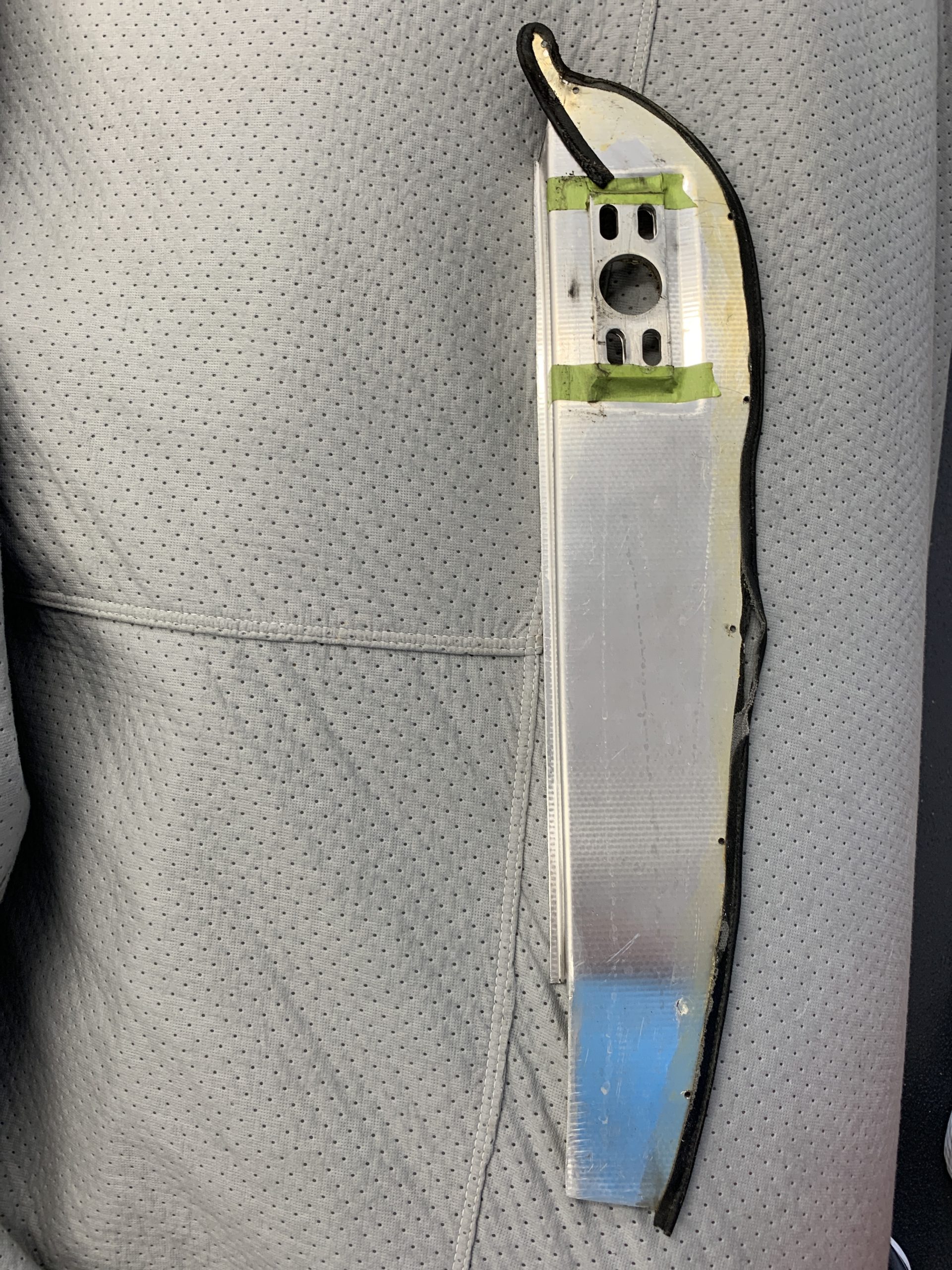
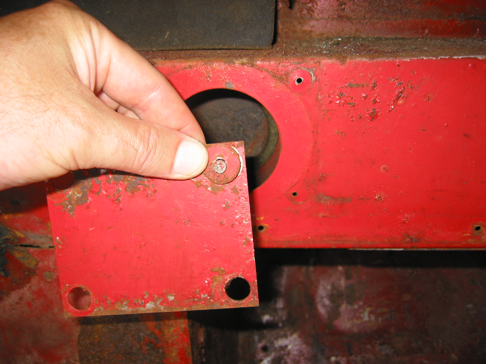
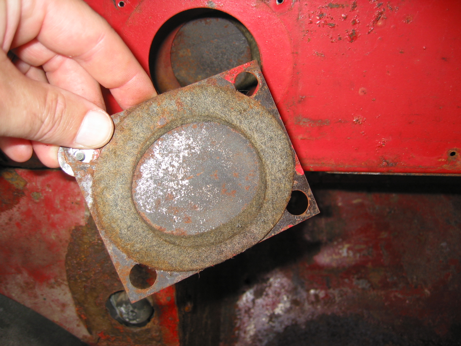
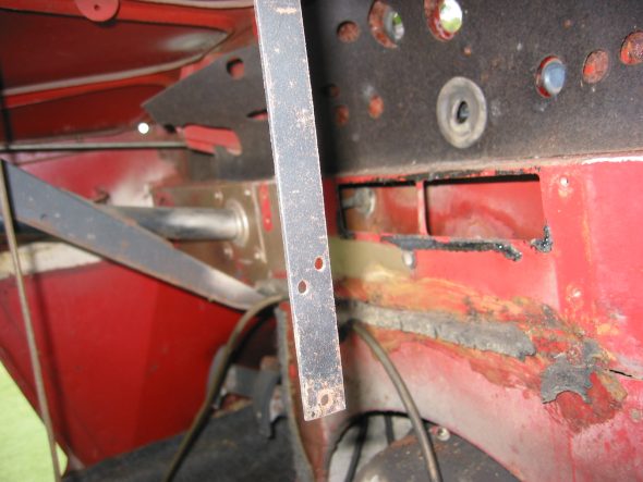
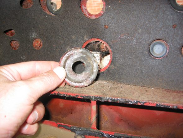
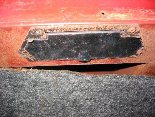
Steering Wheel Shaft Blanking Plate on the right side. Note larger “painted washers” and self tapping screws. Felt gasket found on reverse side of the plate.

Steering Wheel Blanking Plate

Steering Wheel Shaft Blanking Plate Felt Gasket
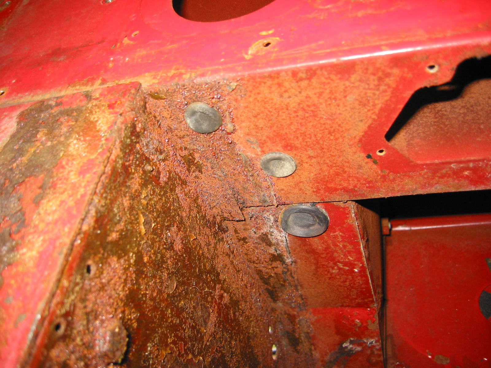
Two Blanking Screws into captive nuts in firewall on passenger side that just fill holes similar to the driver’s side. These were not painted.
Large Wiring Harness Rubber Grommet in center of firewall. Then removed firewall tarpaper in center of firewall. Note the rubber insulation around the heater box hole and along the seam that would otherwise leak air.
Heat Insulation (tar paper) on firewall
Firewall Grommet
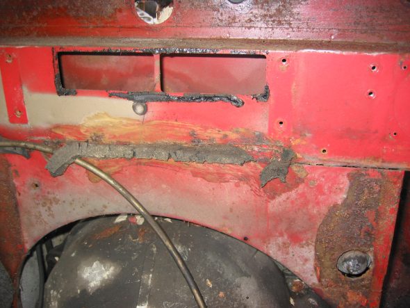
Heater Channel Opening
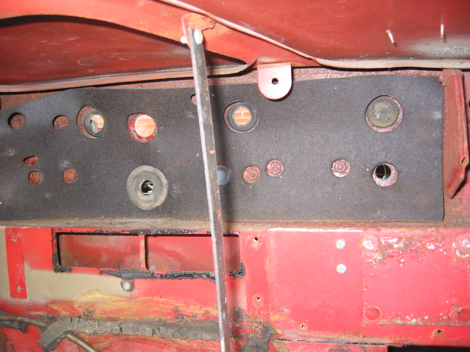
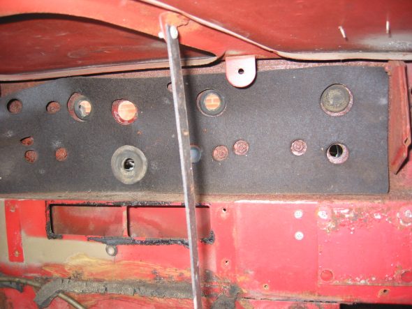
Center Panel Firewall “Tarpaper.” After removing the firewall “tarpaper” that is in three pieces I numbered the holes:
#1 – Bonnet release rod grommet
#2 – Blank Cover grommet
#3 – Grommet
#4 – Brake Line clip
#5 – Grommet
#6 – Grommet
#7 – Nut
#8 – Nut
#9 – Brake Line Clip
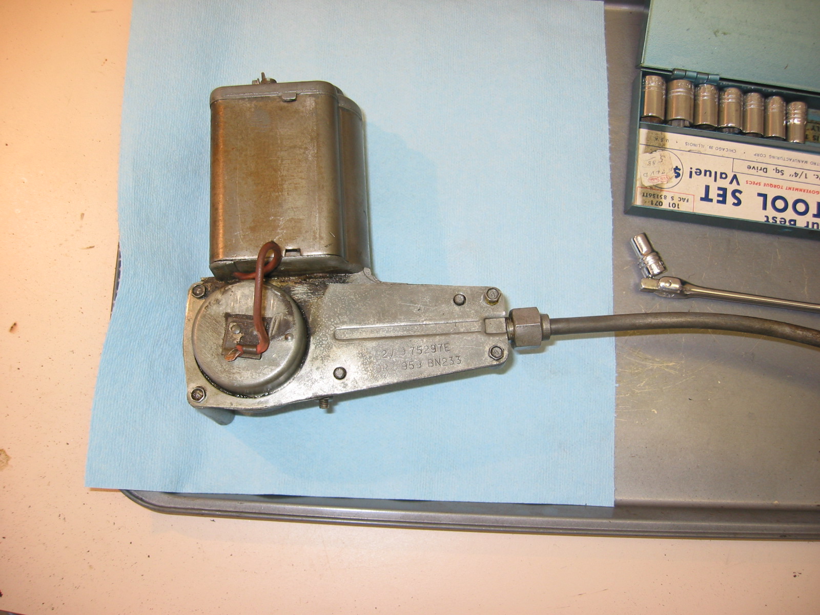
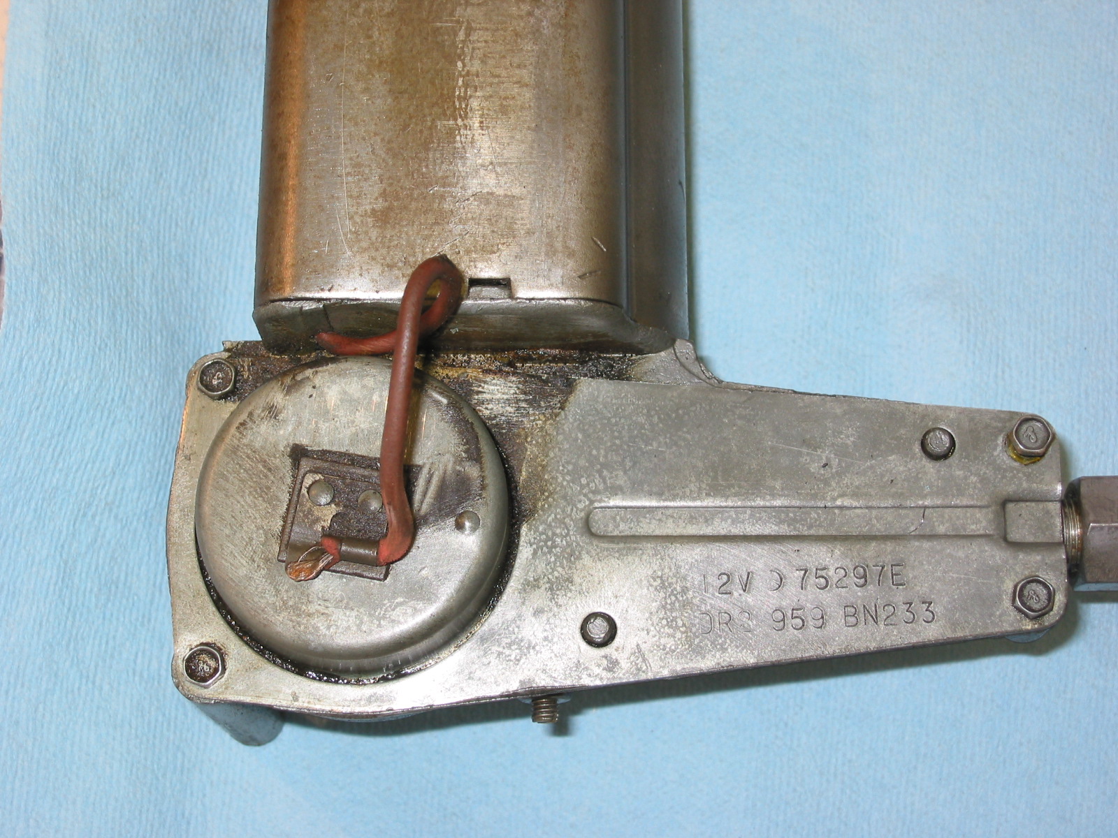
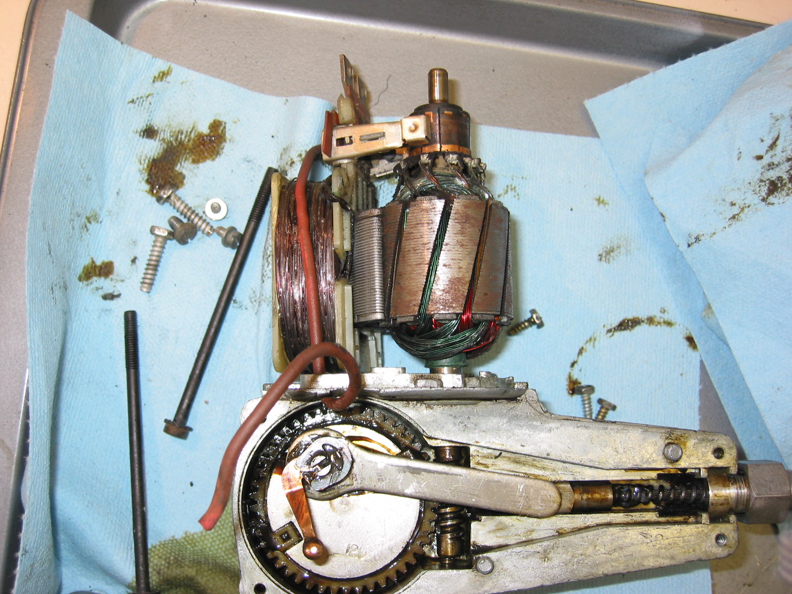
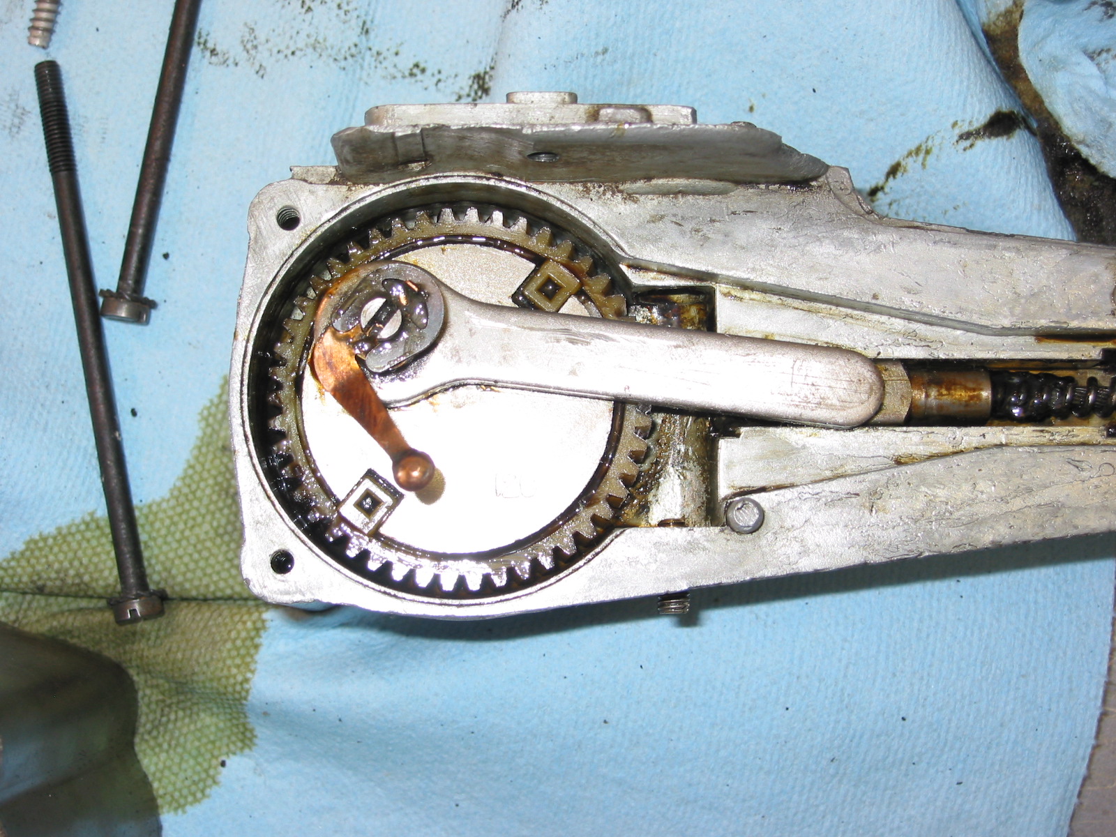
#10 – 1 Nut, 2 grommets Wiper motor
#11 – 2 Nuts
#12 – Nut
#13 – Nut
#14 – Nut
#15 – Nut
#16 – Main wiring harness to dash
#17 – Blank Cover Grommet
#18 – Nut
#19 – Nut
#20 – Nut
#21 – Grommet
Left Panel Firewall “tarpaper”:
#22 – H2O temp. line
#23 – Oil line
#24 – Nut
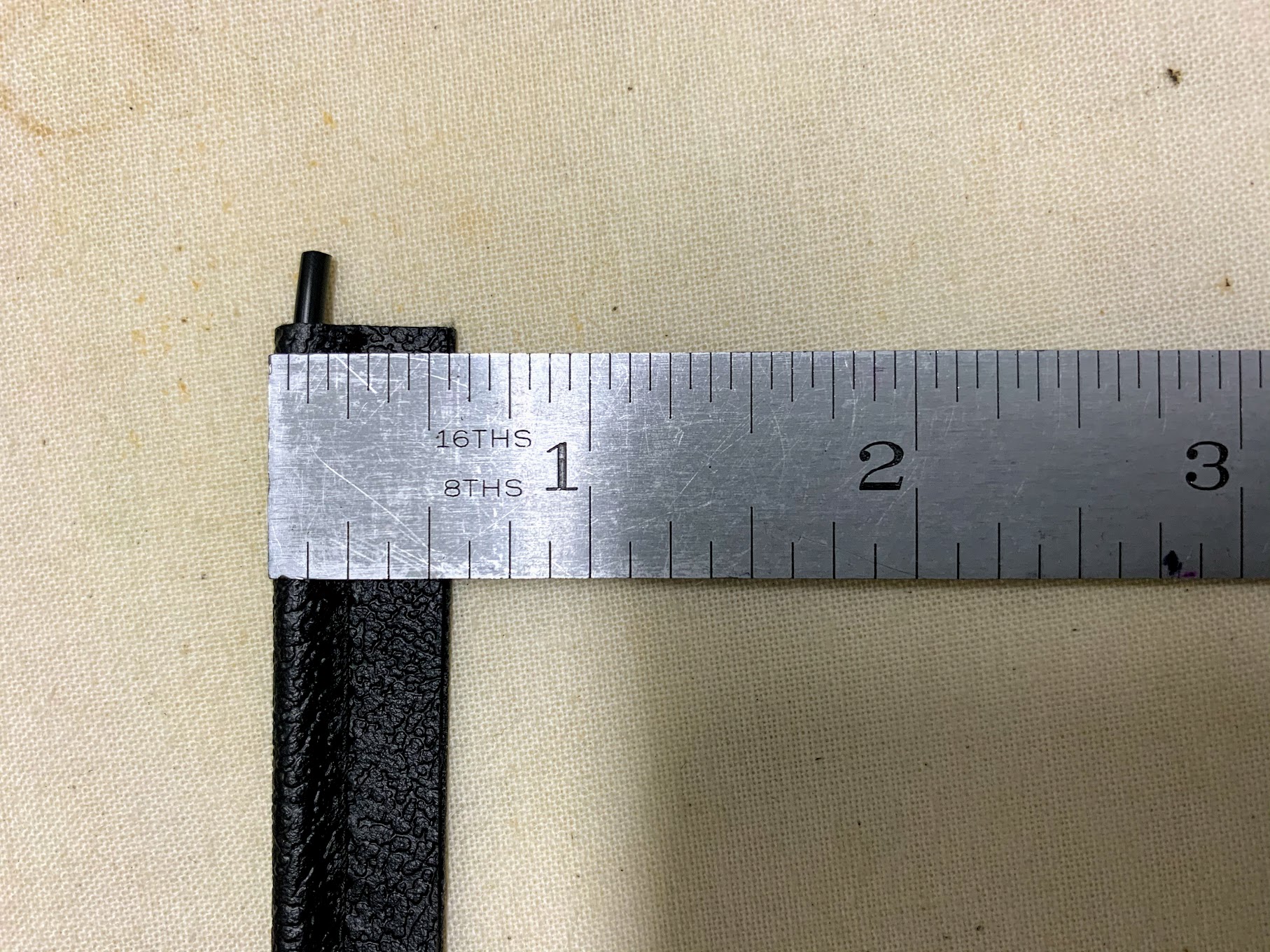
Small Blanking Rubber Grommets under the heater opening in firewall.
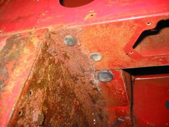
Blanking Rubber Grommets
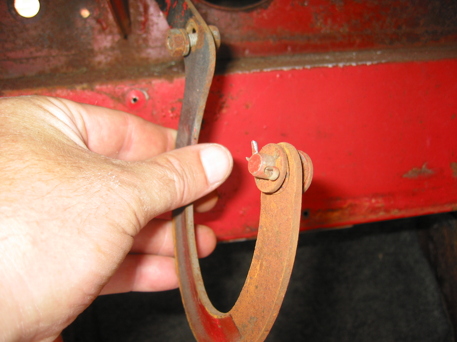
Right Bonnet Hinge cotter pin and 4 washers. The thin washers go closest to the hinge. The nuts go to the inside of the bonnet.
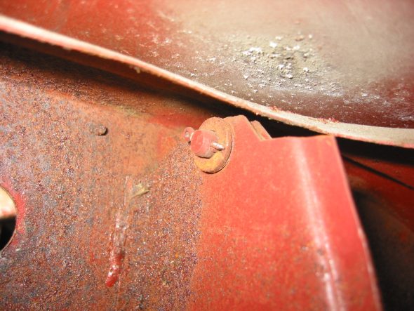
Bonnet Hinge Fixing
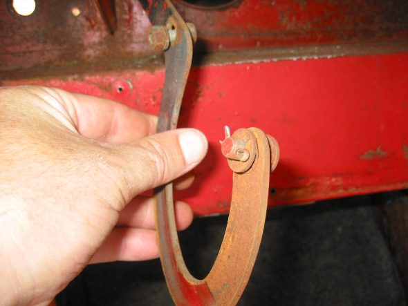
Bonnet Hinge
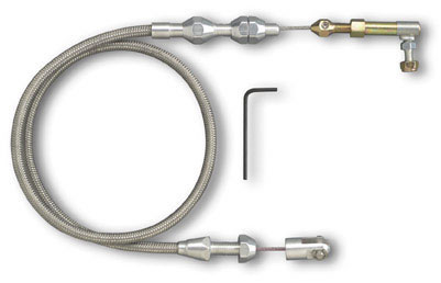
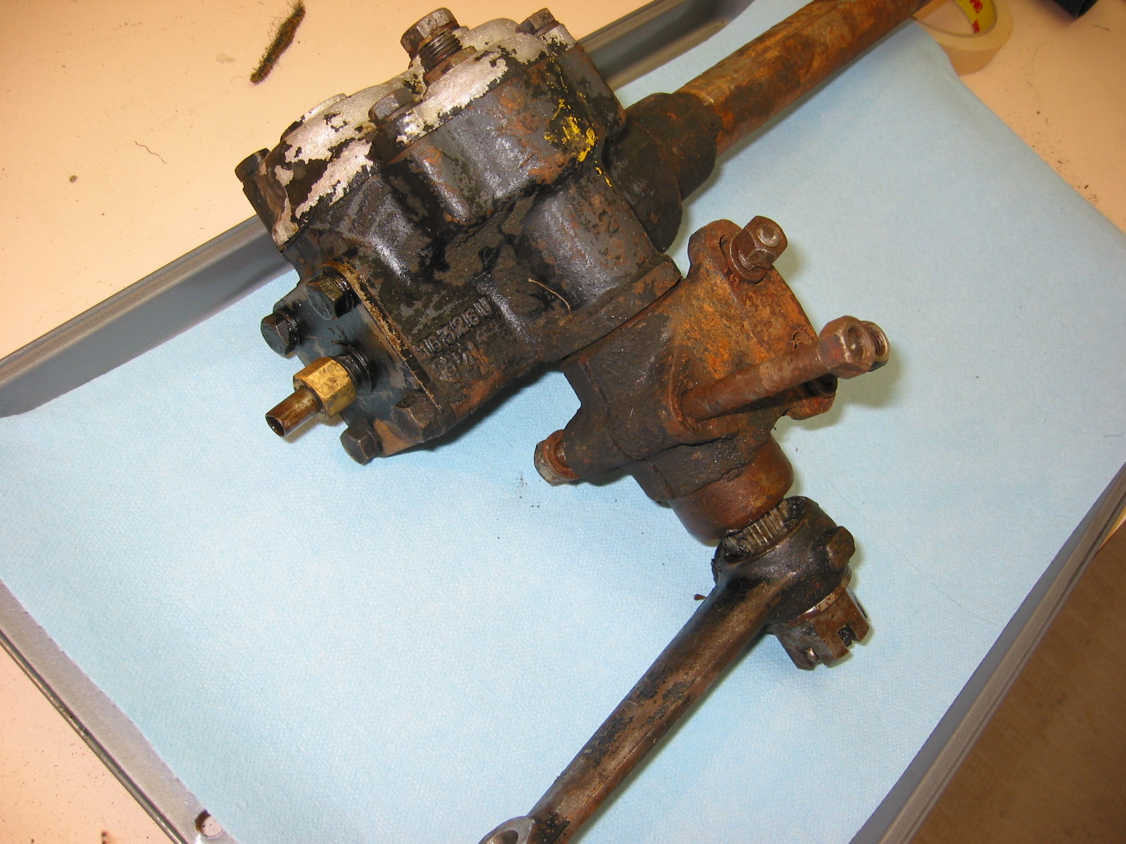
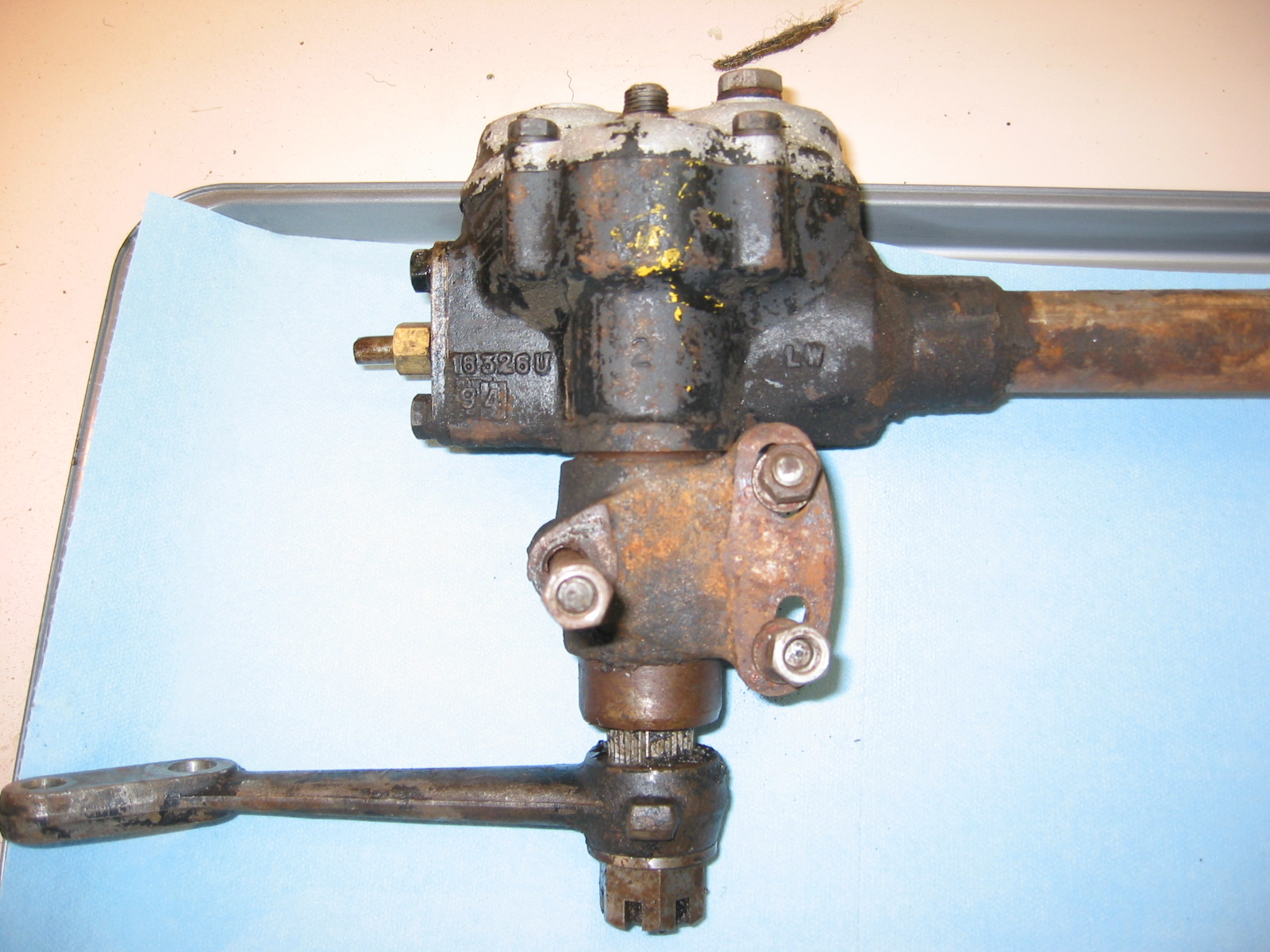
Speedometer Cable at “L” junction to the gearbox.
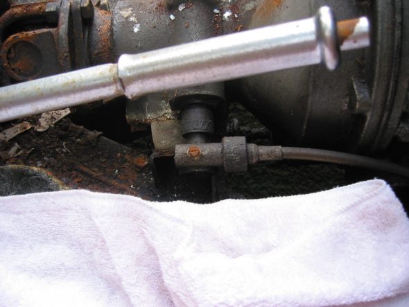
Speedometer Cable to Gearbox
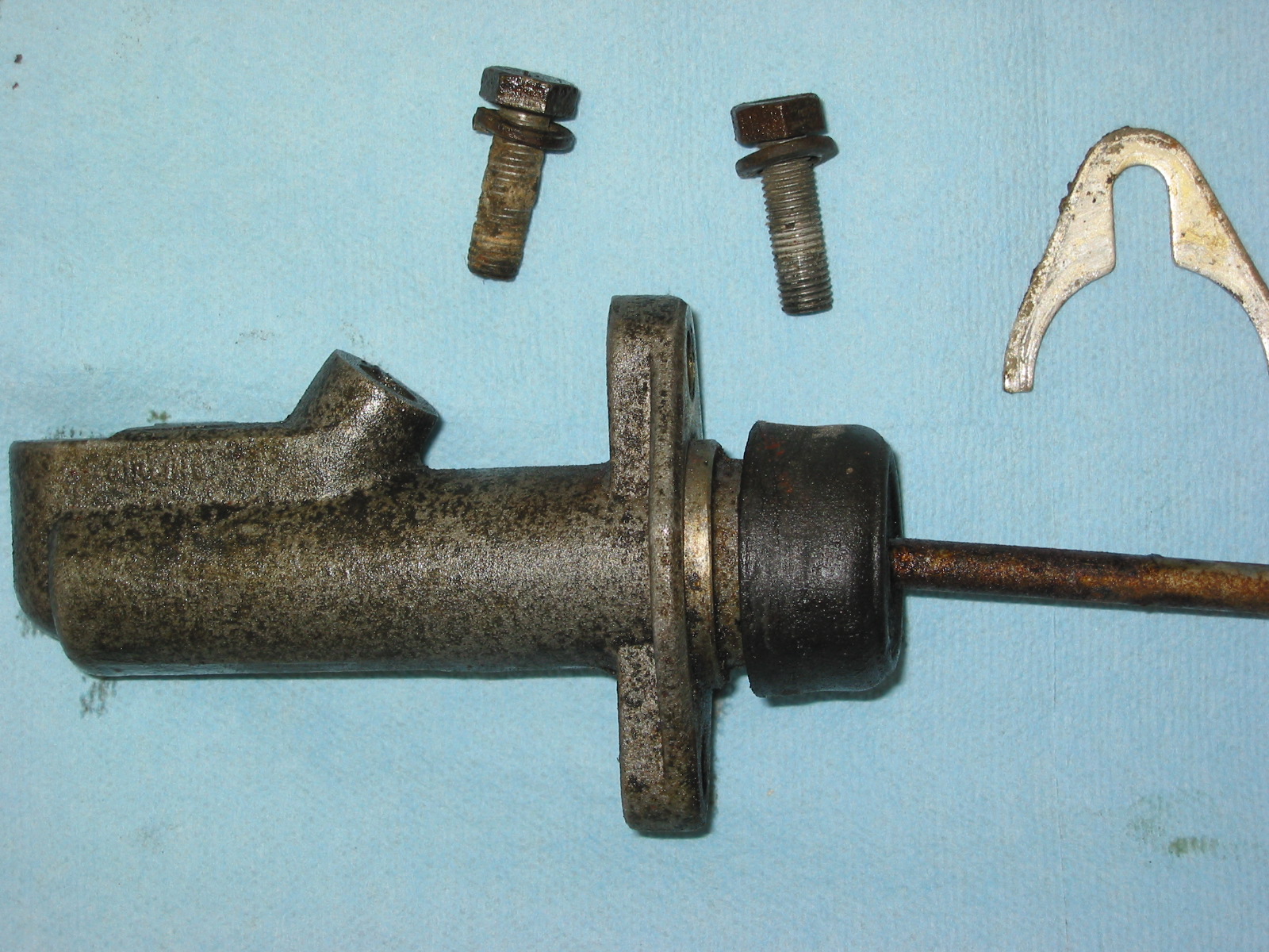
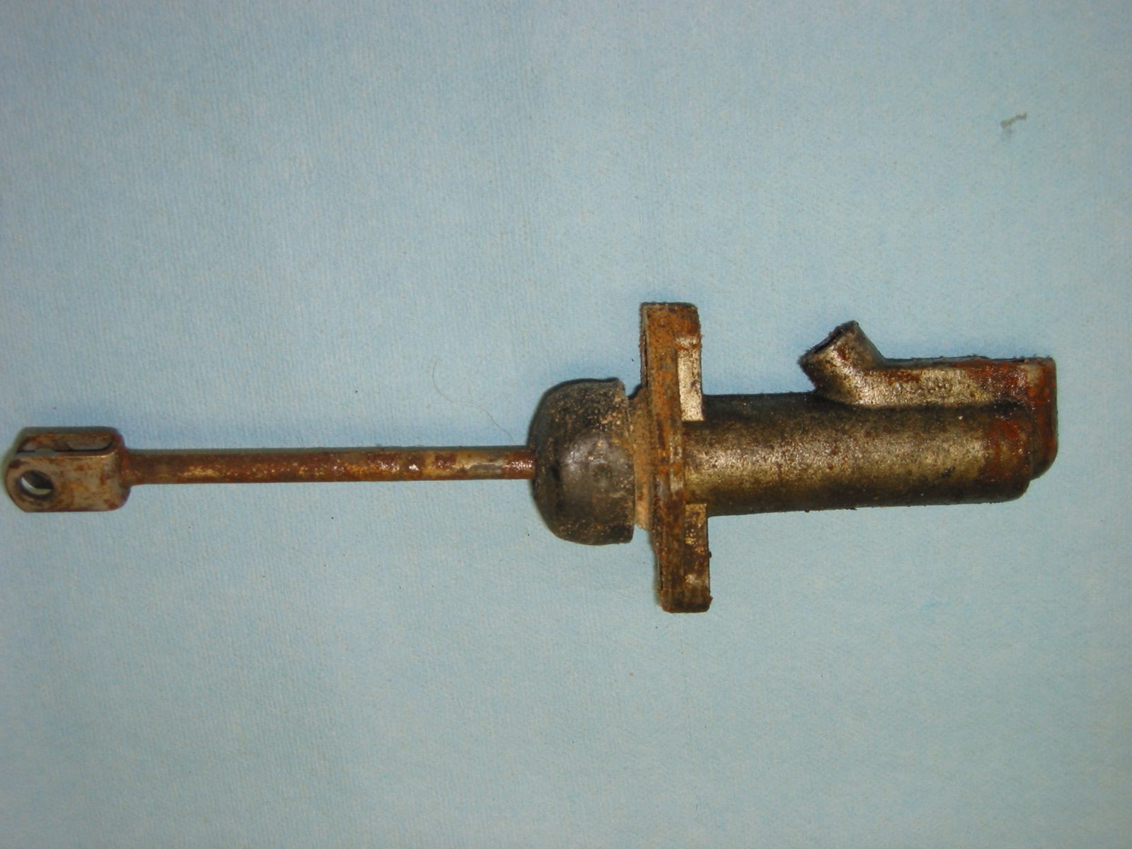
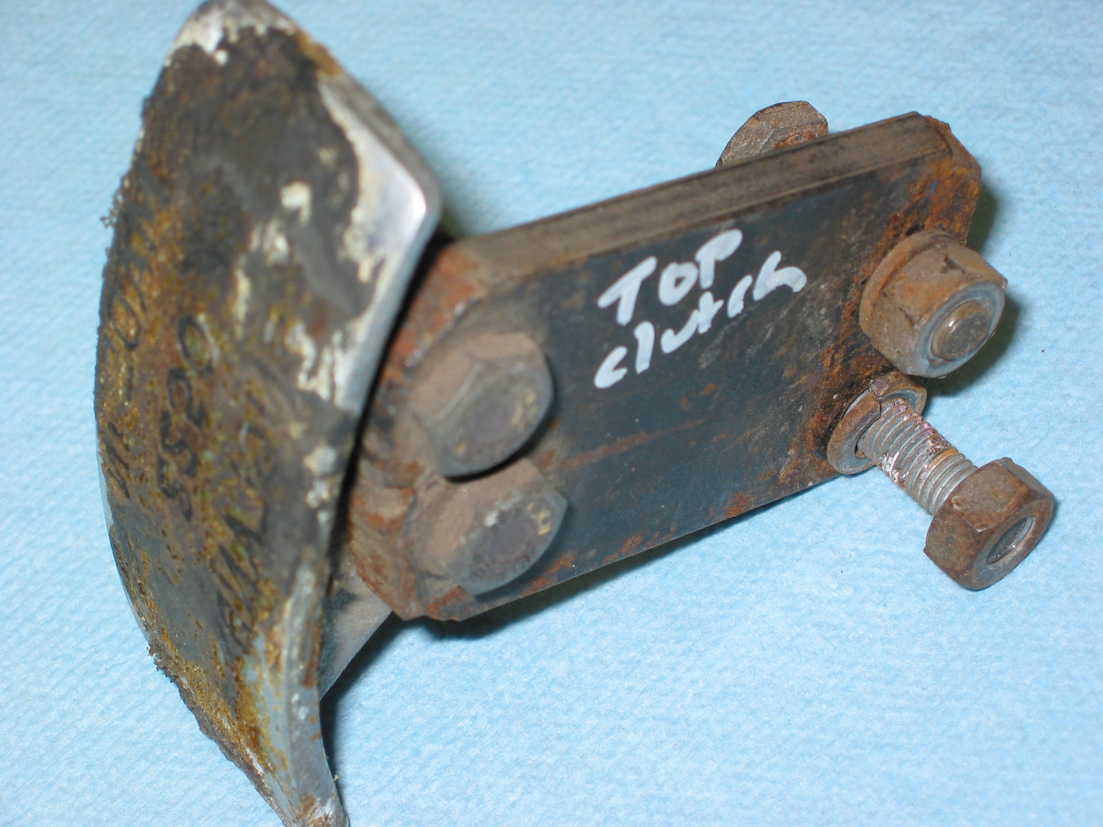
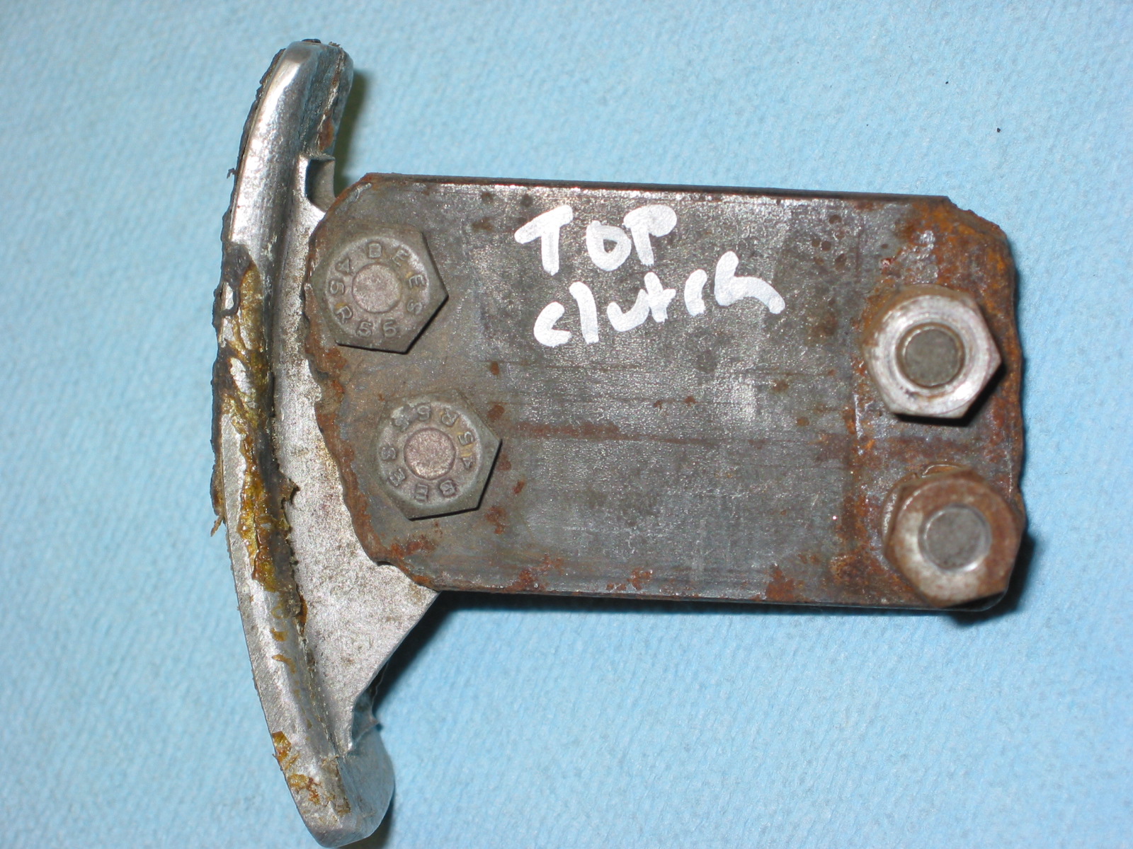
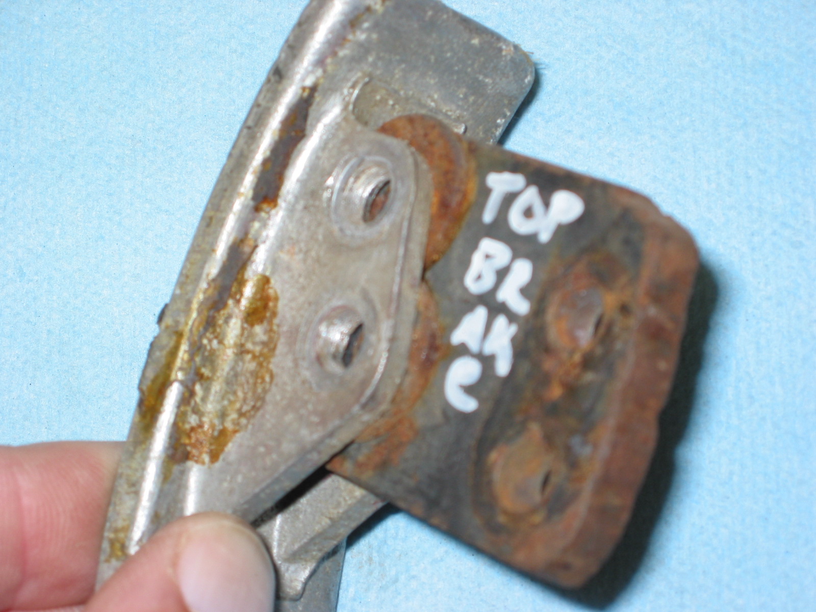
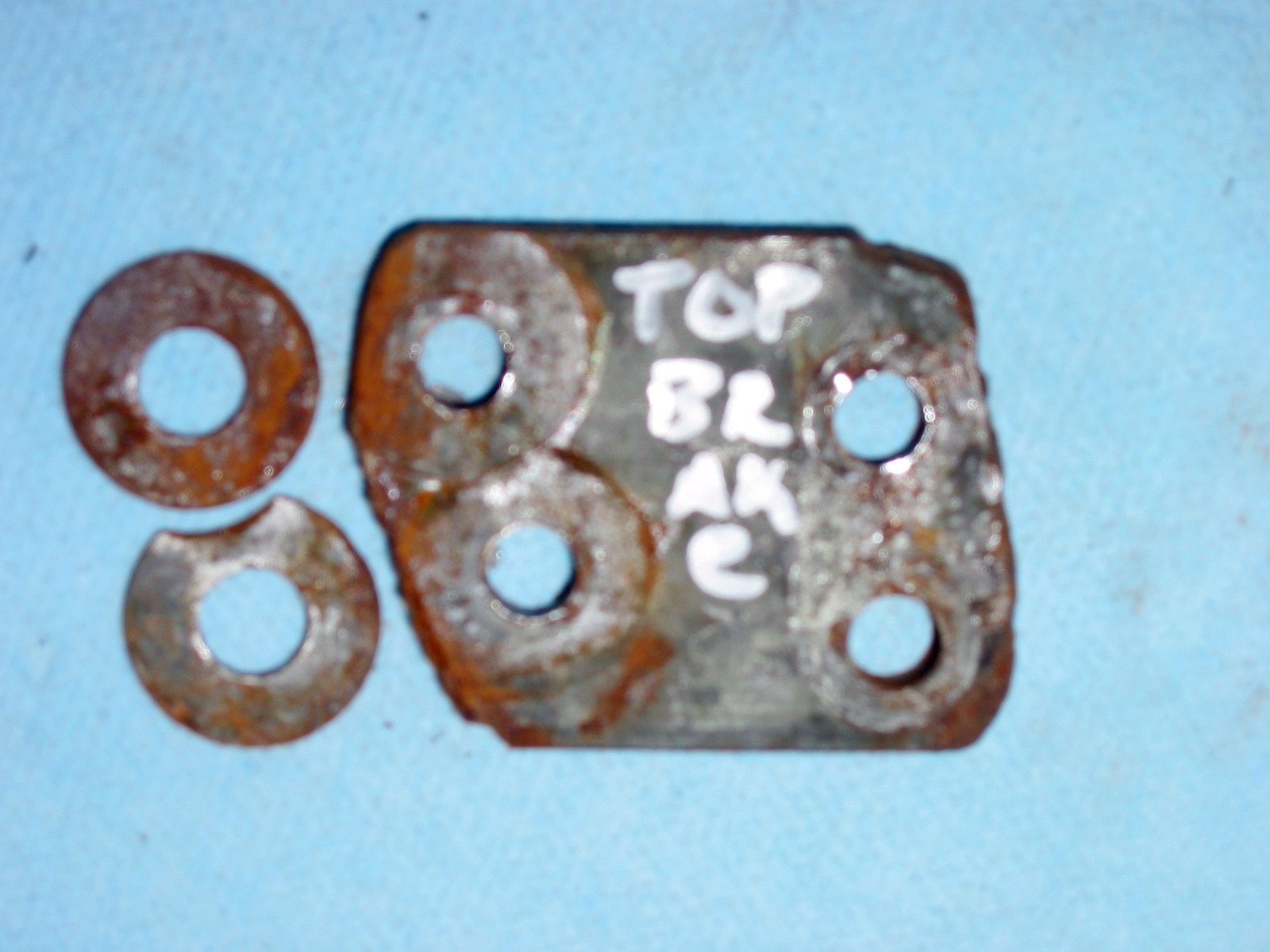
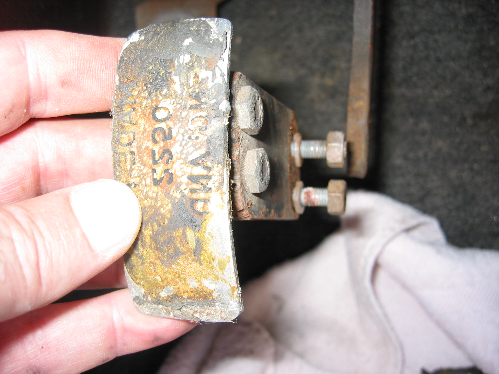
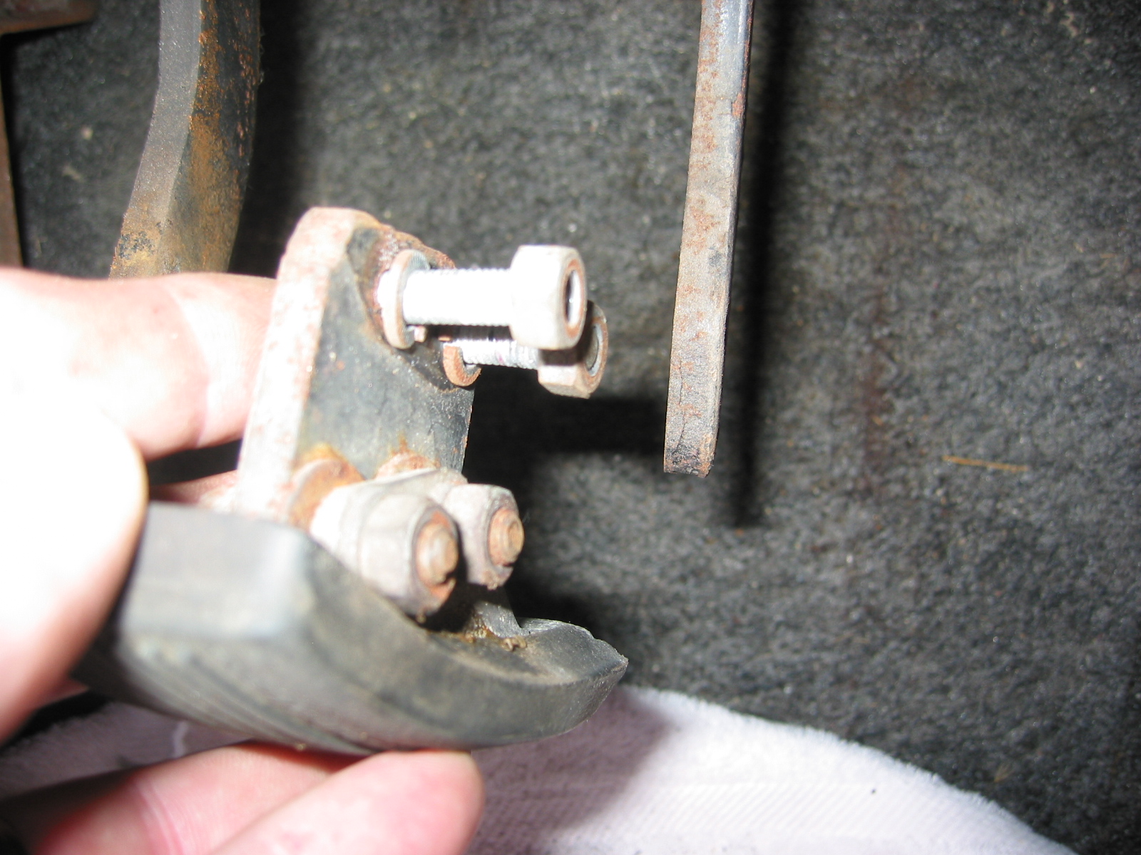
Clutch Pedal from pedal bar – two nuts. The nuts go to the right side. Removed the Brake pedal from pedal bar – two nuts with nuts to the right side. I noticed at this point that some primatively cut spacers had been added to the pedals for a short-legged driver!

Clutch Pedal
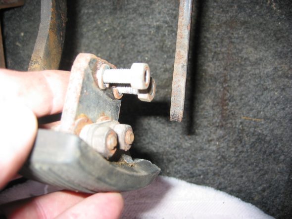
Clutch Pedal Spacer
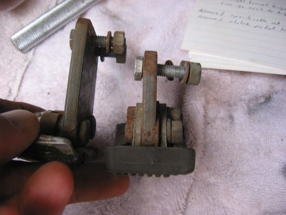
Pedal Spacers
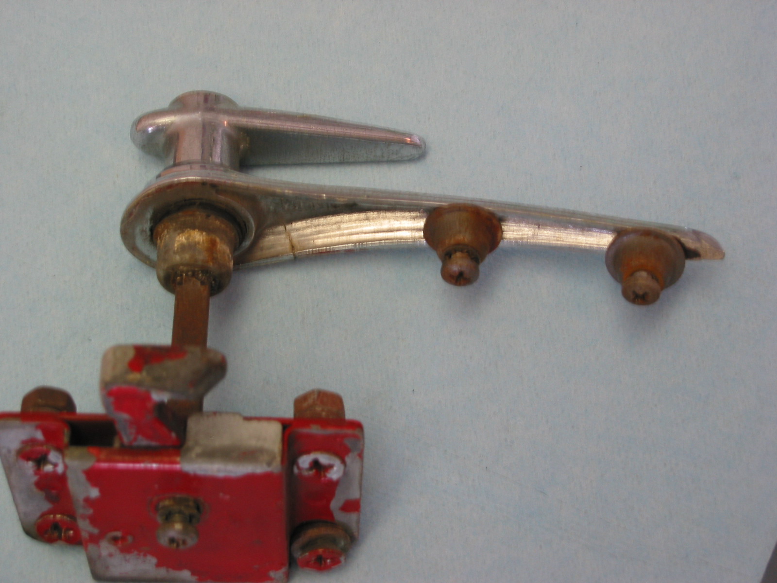
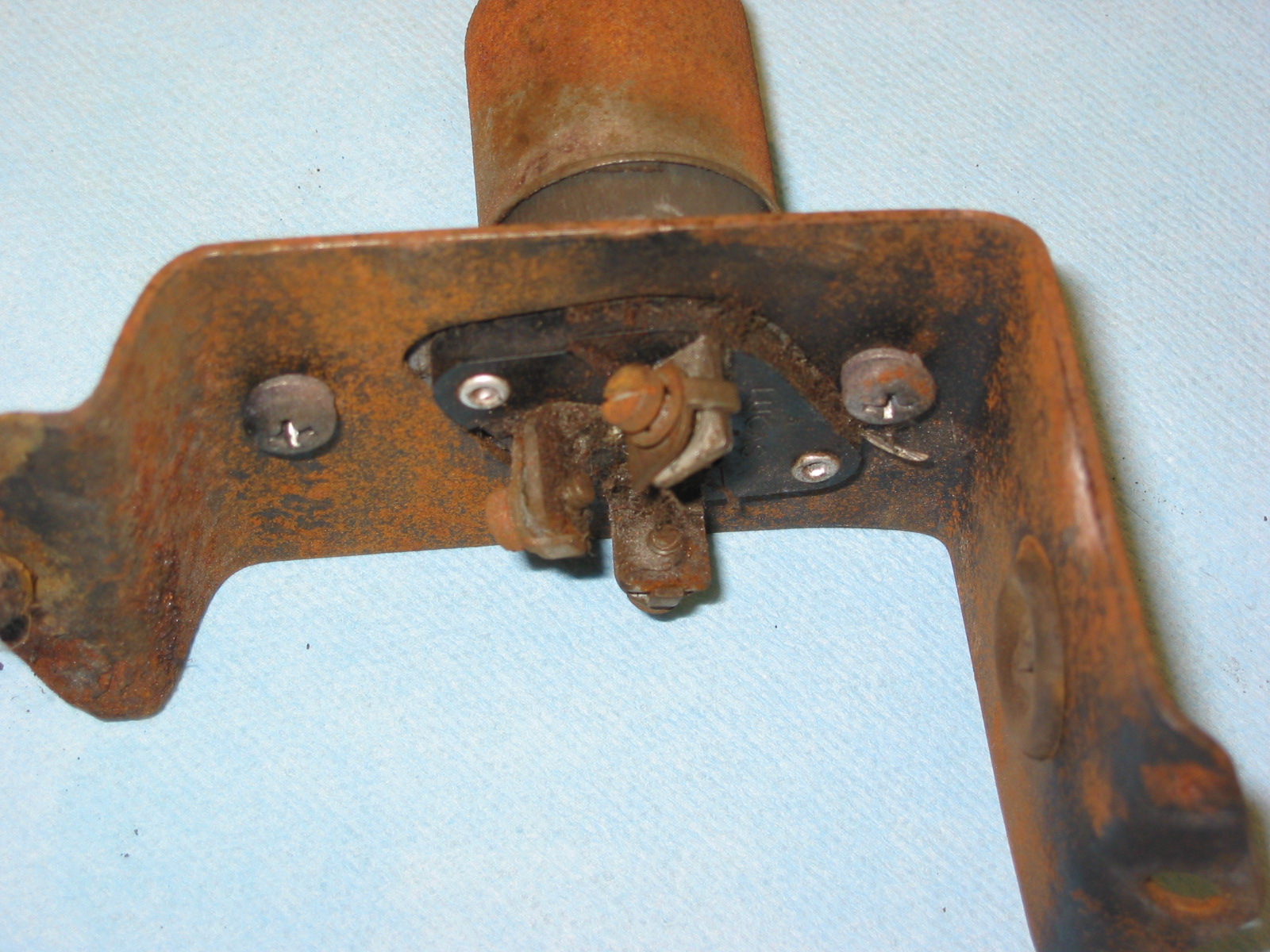
Floor Dip Switch with two bolts to the fixed nuts in floor. 3 wires: red/blue, blue/white, all blue.
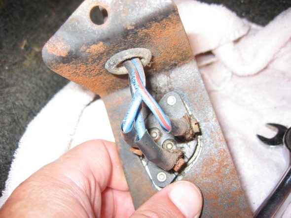
Dip Switch Wiring and Bracket
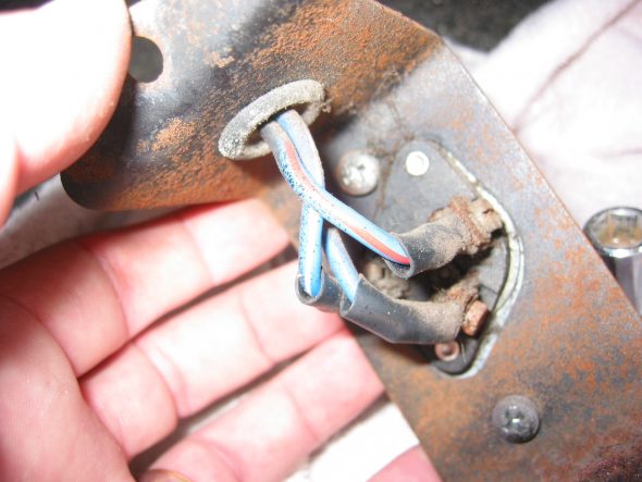
Dip Switch
Heater Vents on both driver and passenger side below dash. Four self tapping screws in each
Heater Fresh Air Vent Door
July 2, 2002
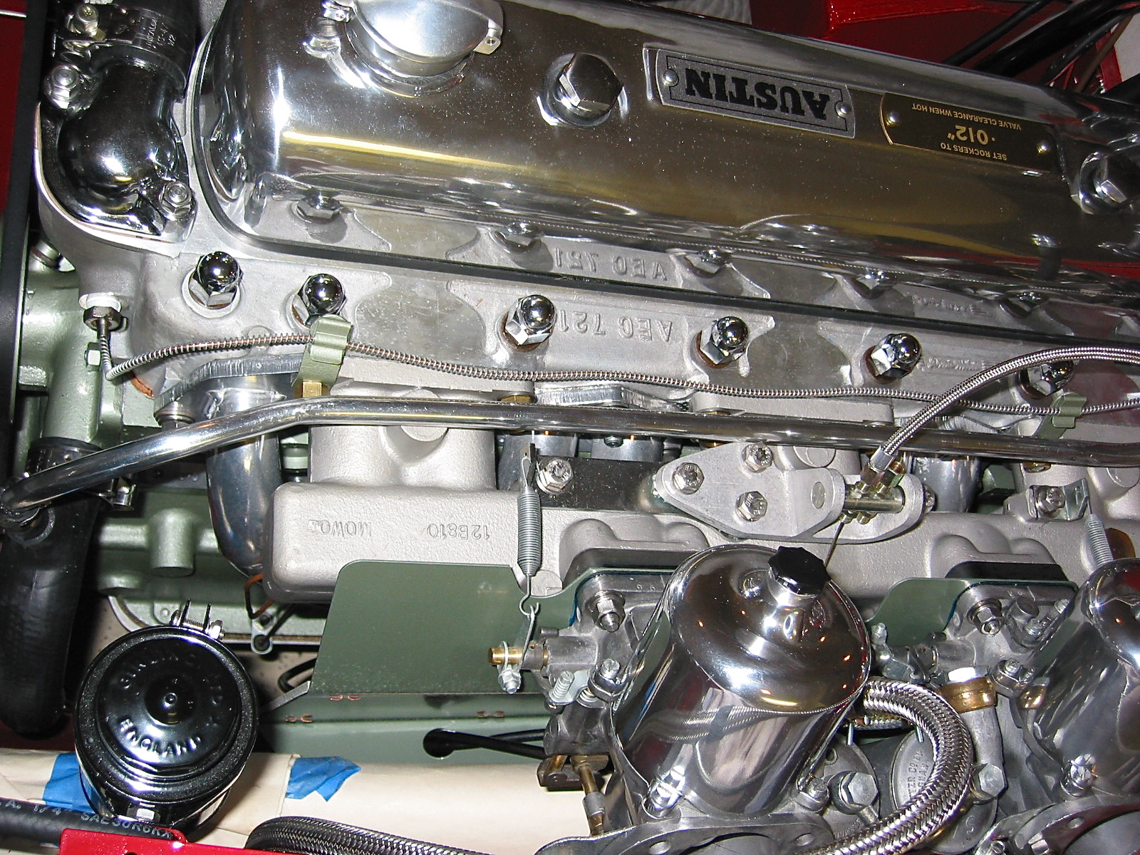
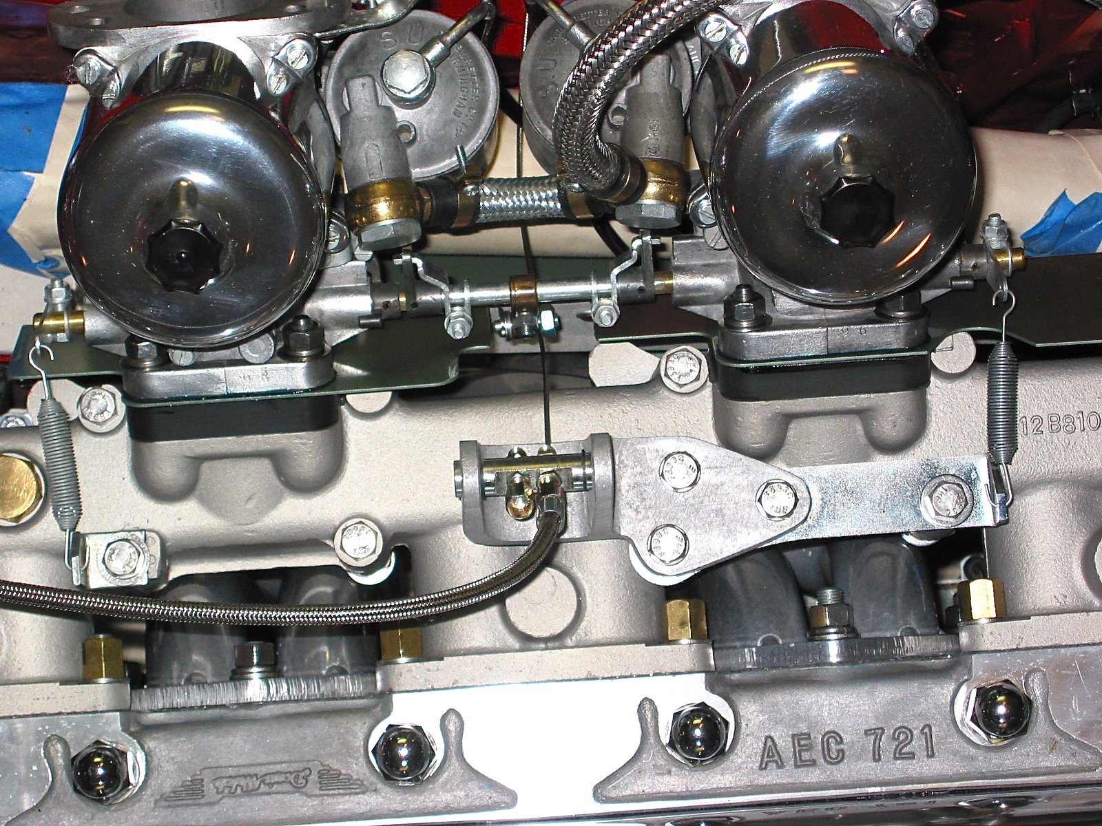
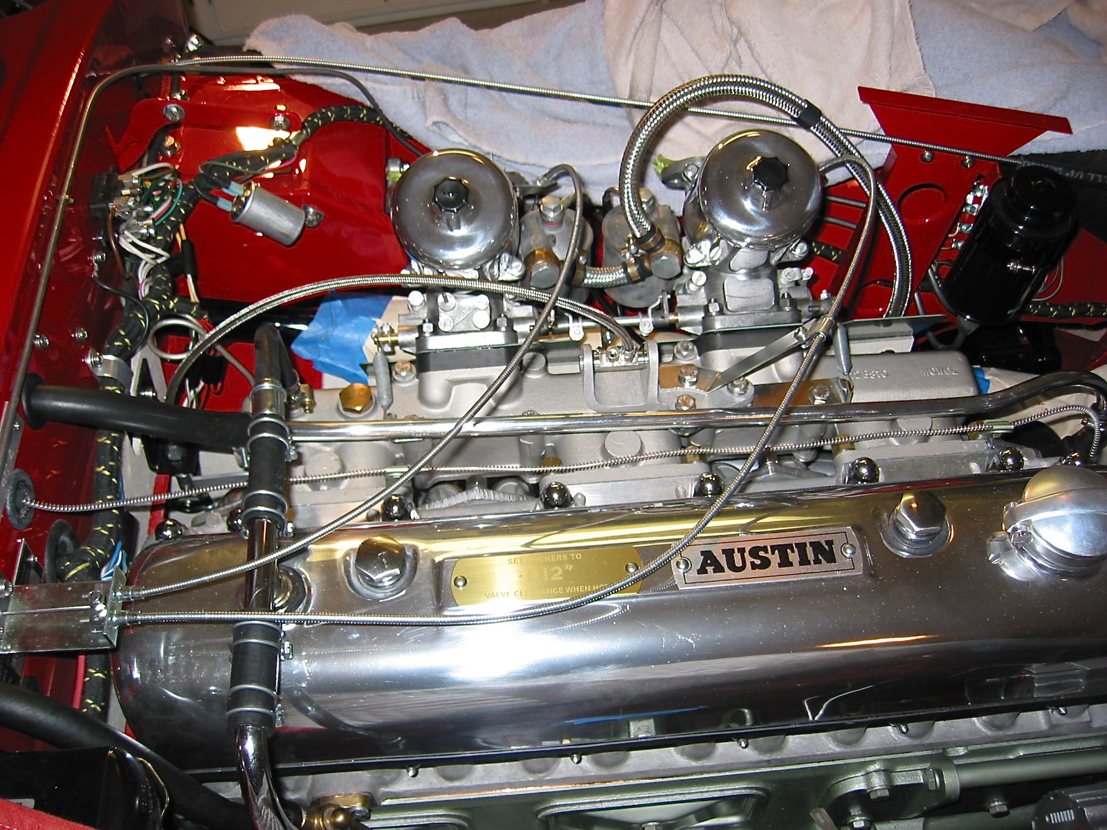
Engine
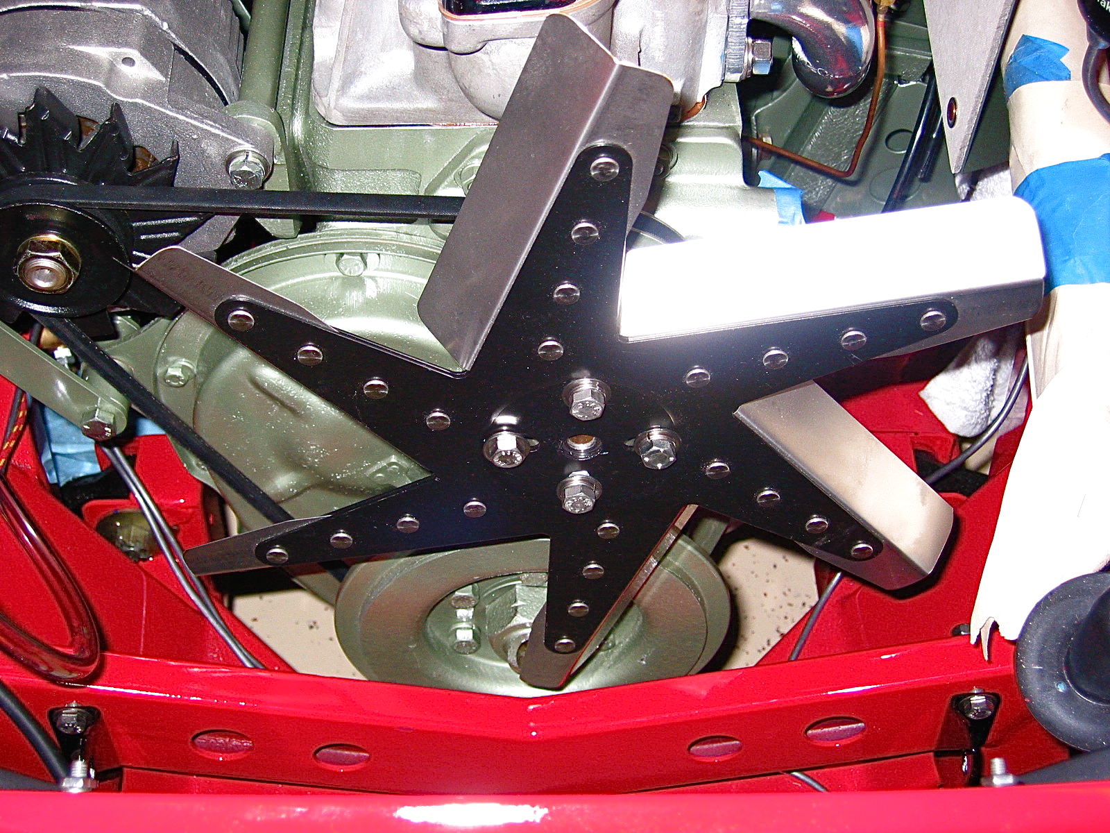
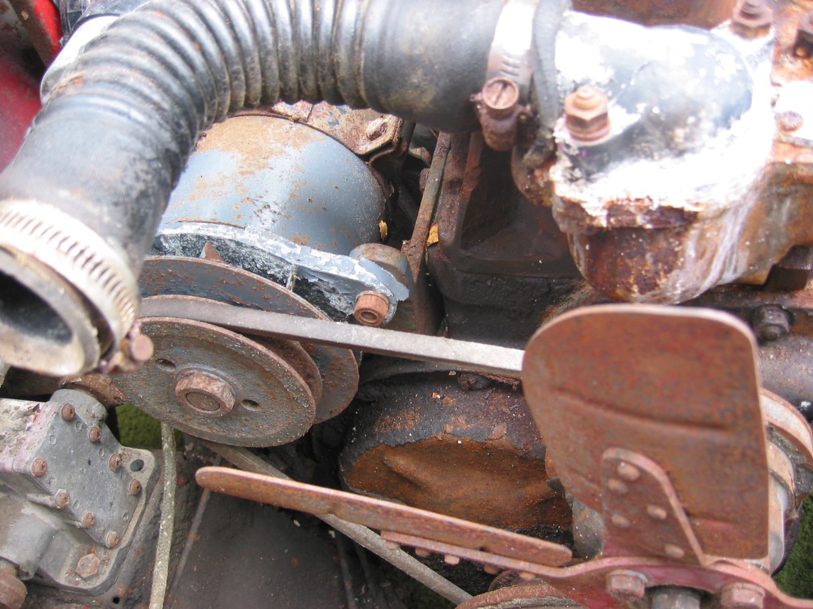
Fan and fan belt – Loosened 4 bolts and washers and removed the fan and fan belt.
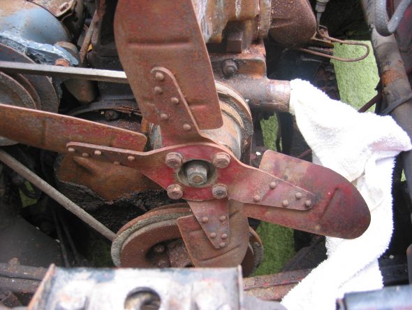
Fan and Fan Belt
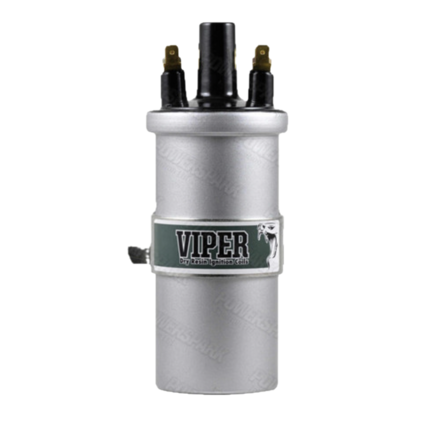
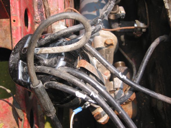
Wiring to the coil – CB Terminal – White with black stripe from/to the distributor body and white with black stripe from harness that goes to the generator. SW Terminal – Large solid white wire from harness to generator.
Coil Wiring
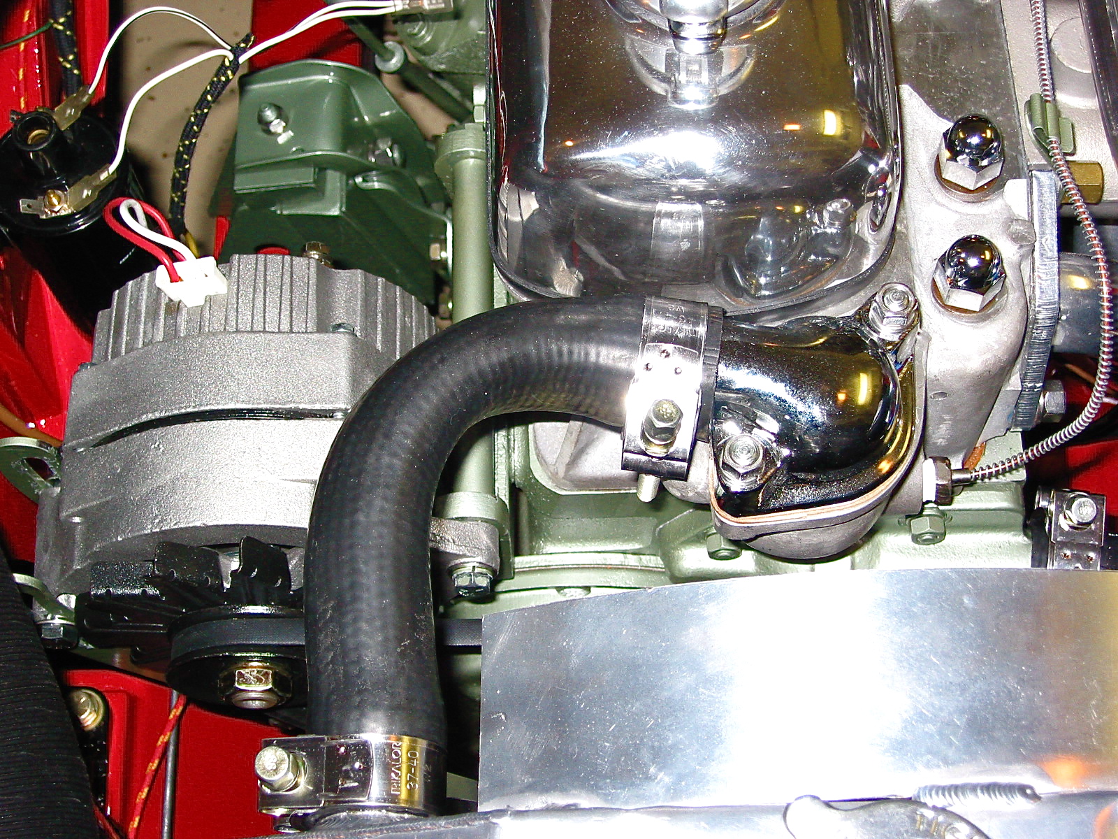
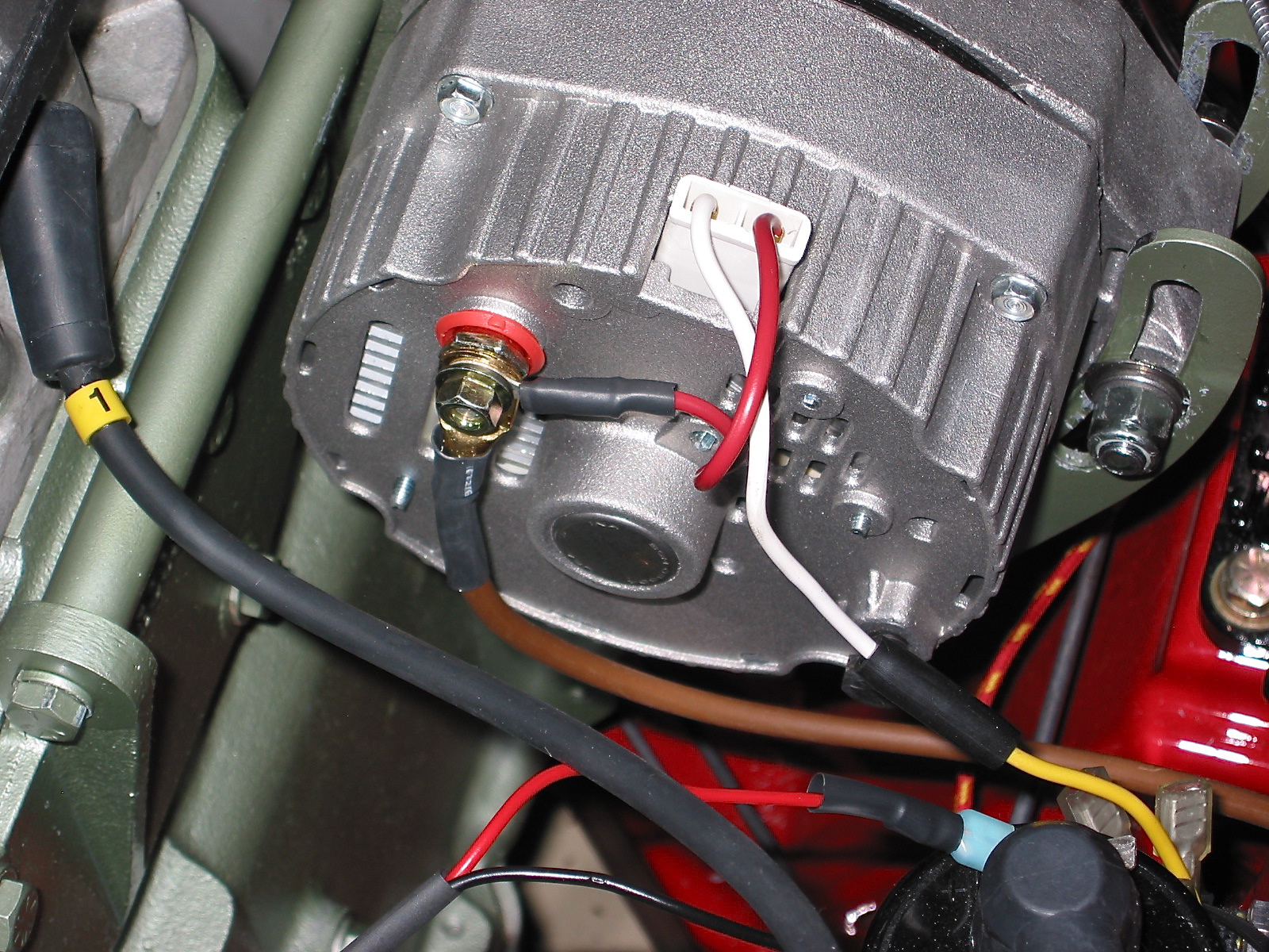
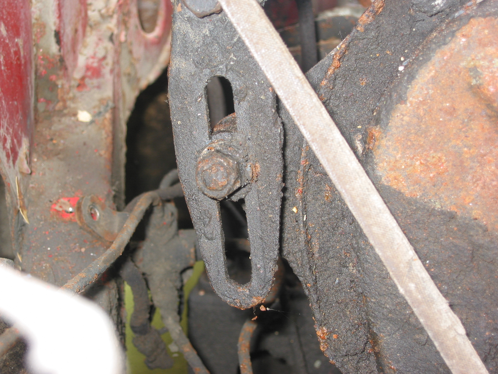
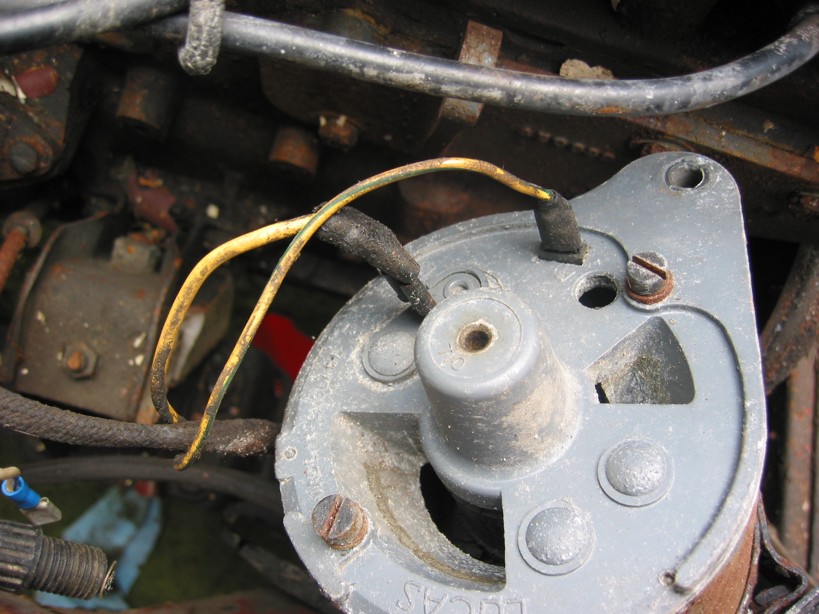
Generator – Removed 2 bolts and nuts and adjusting bracket with self-locking nut. F Terminal – yellow/green stripe wire from harness. D Terminal – Large solid yellow wire connected to large spade.

Dynamo – Generator
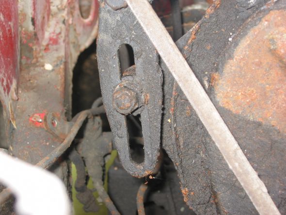
Generator Adjustable Mounting Bracket

Generator Wiring
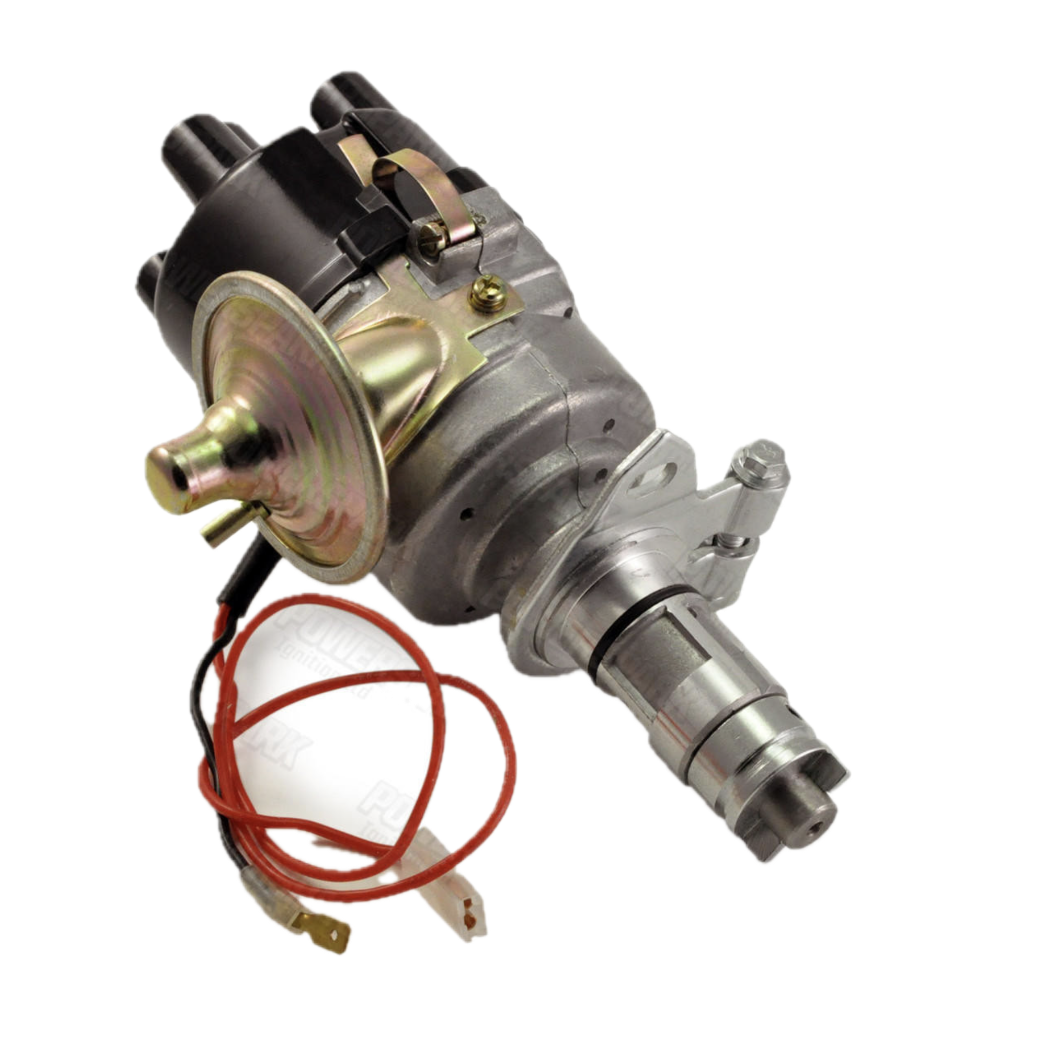
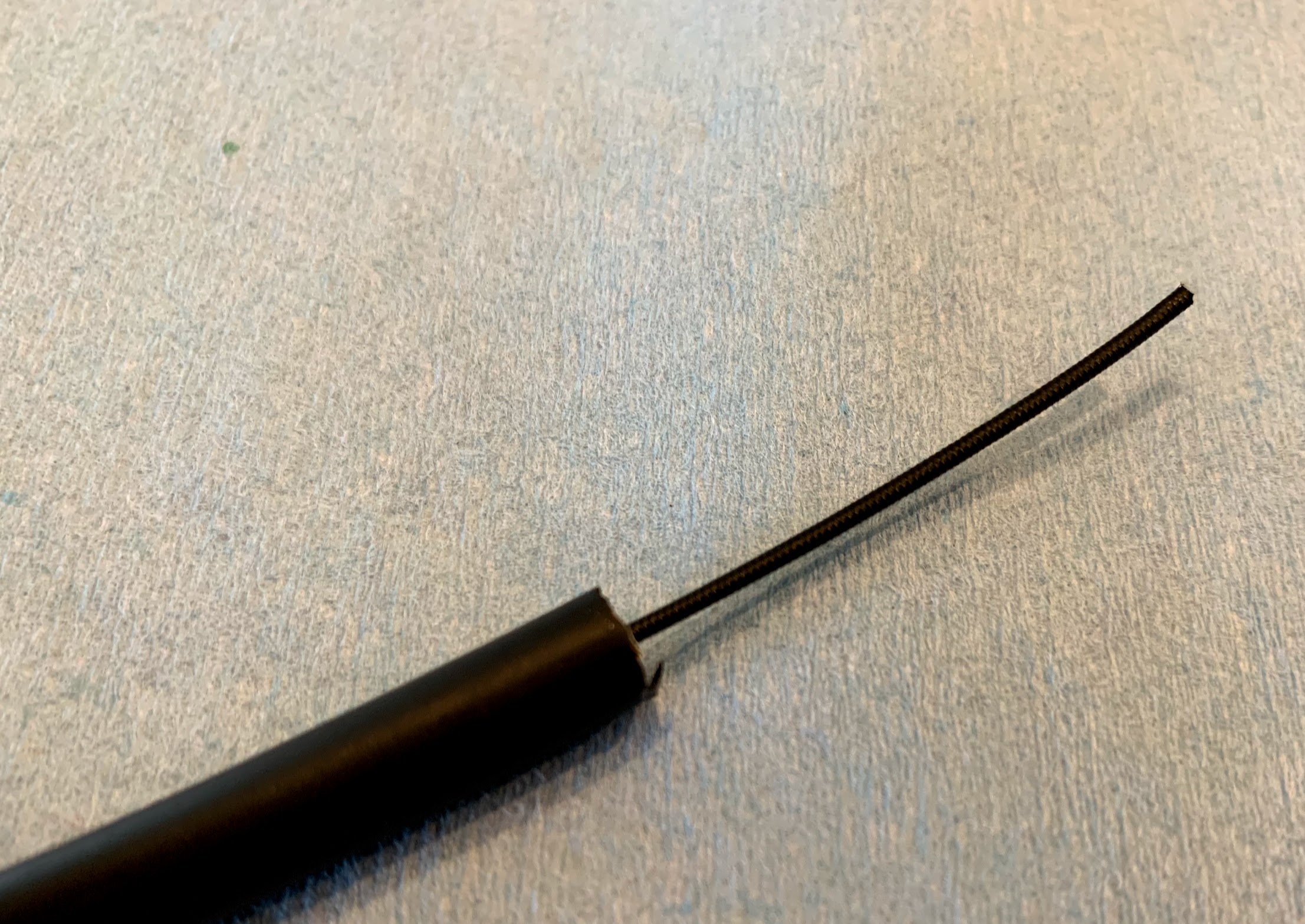
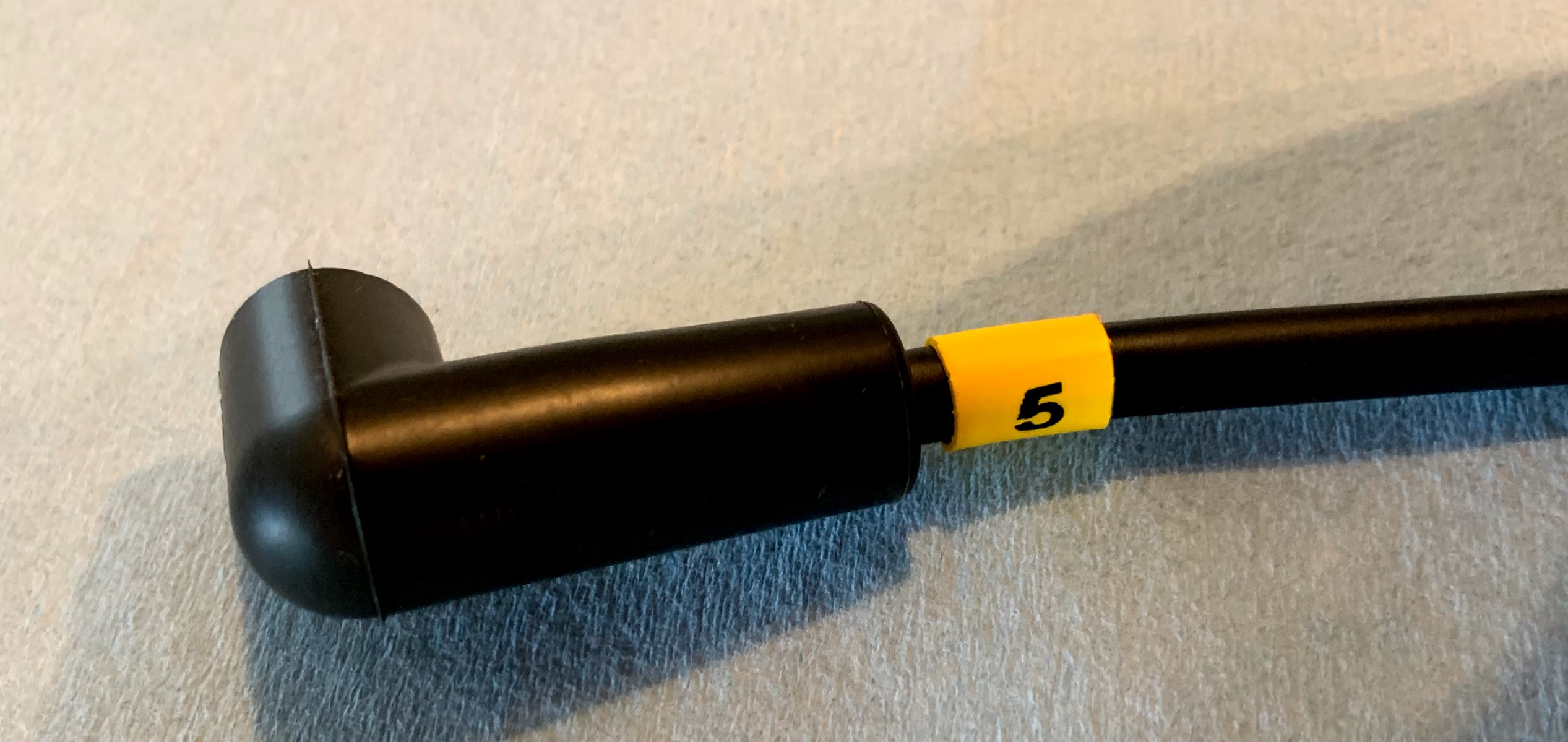
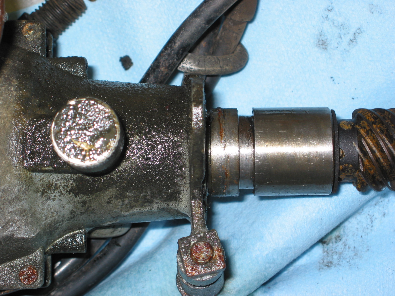
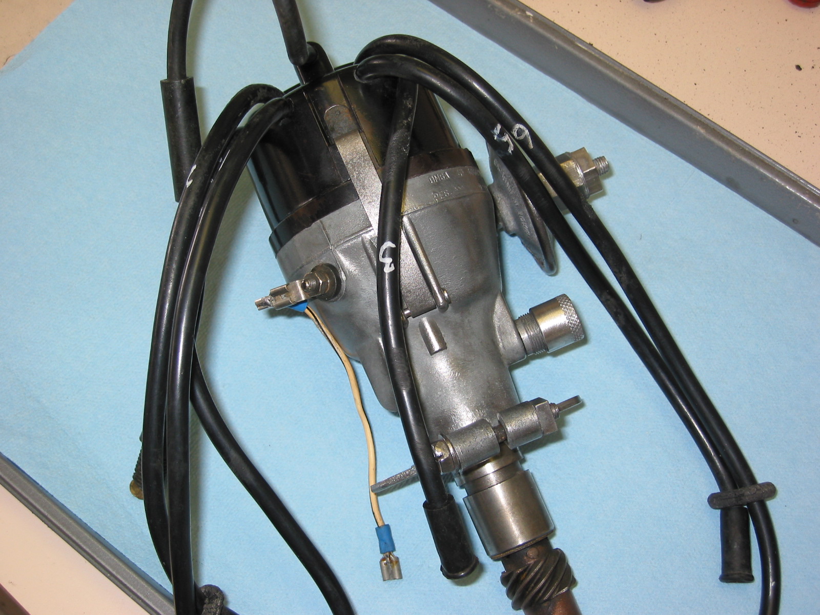
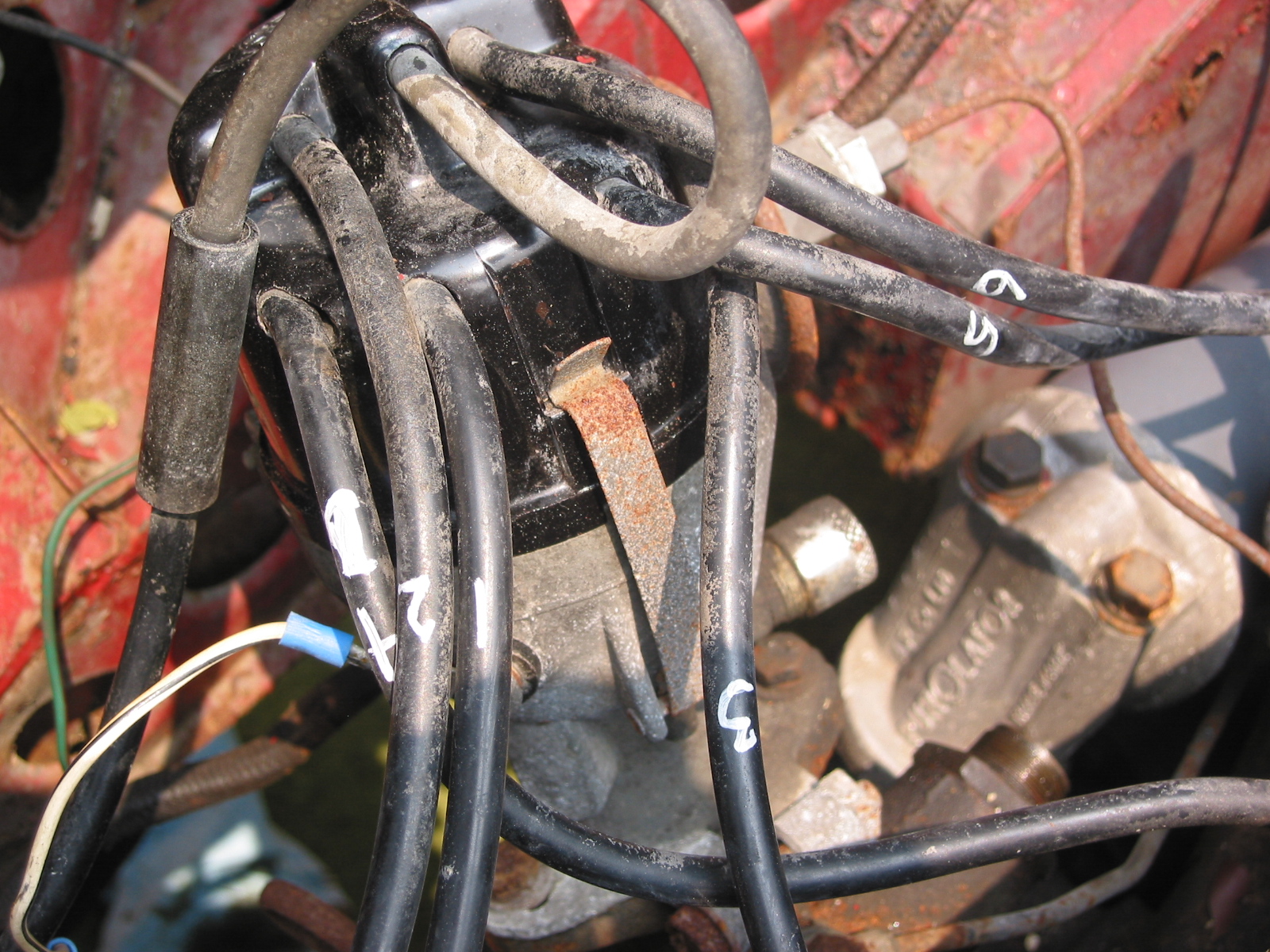
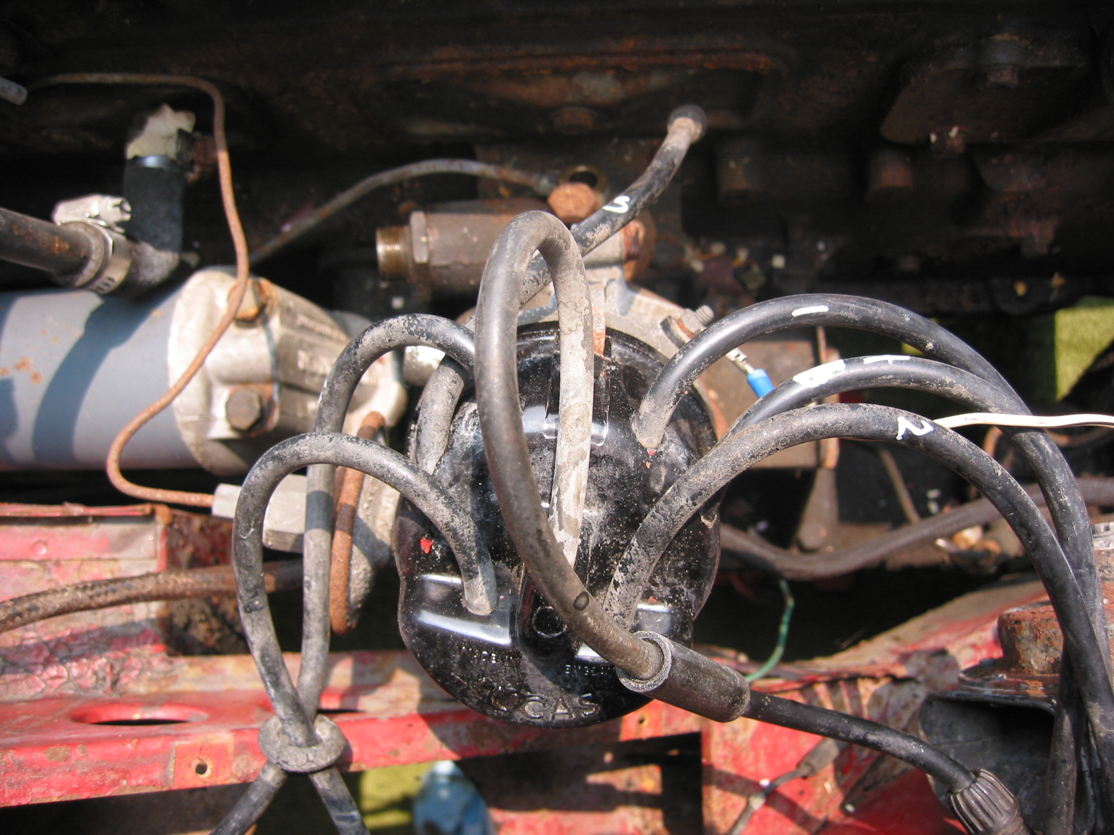
Distributor – Removed two 7/16” bolts – note position of distributor and vacuum advance. Numbered each wire to the correct cylinder. Disconnect vacuum line and oil feed line to the tachometer drive.
Distributor Wiring

Distributor

Distributor Cap

Distributor Mounting Clamp
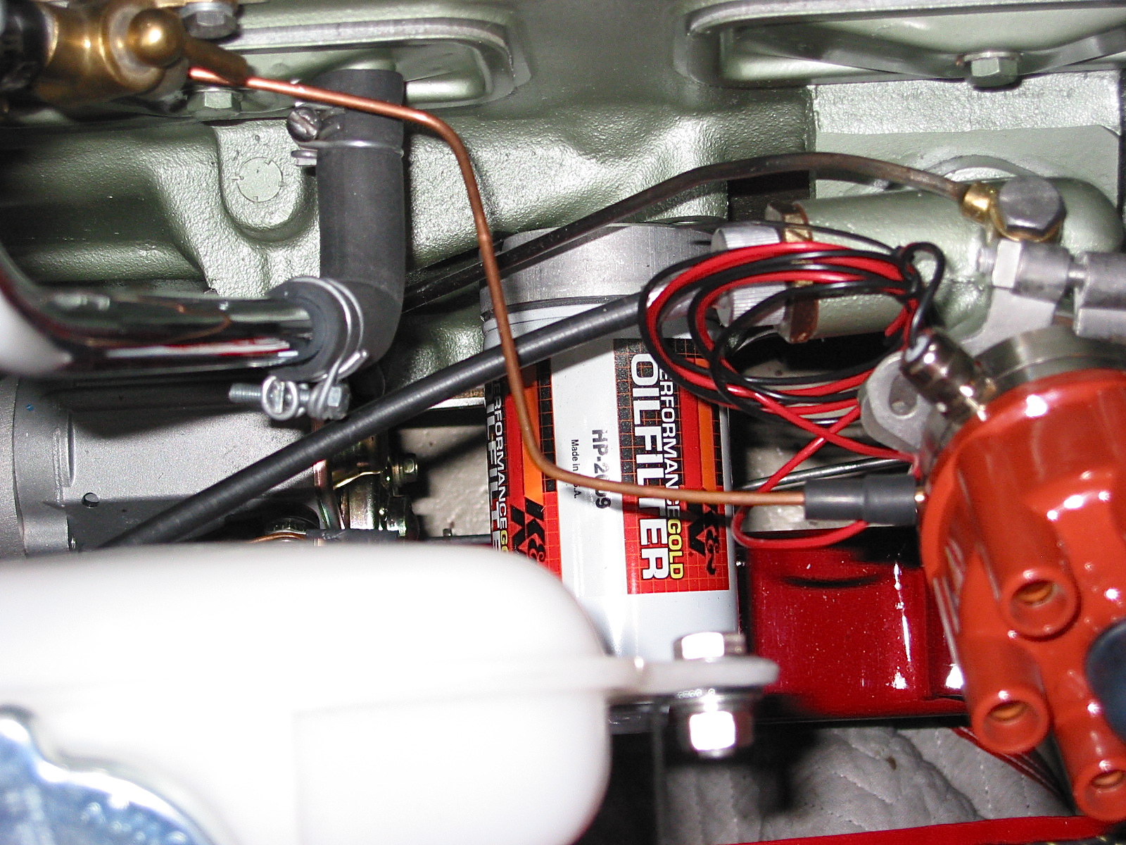
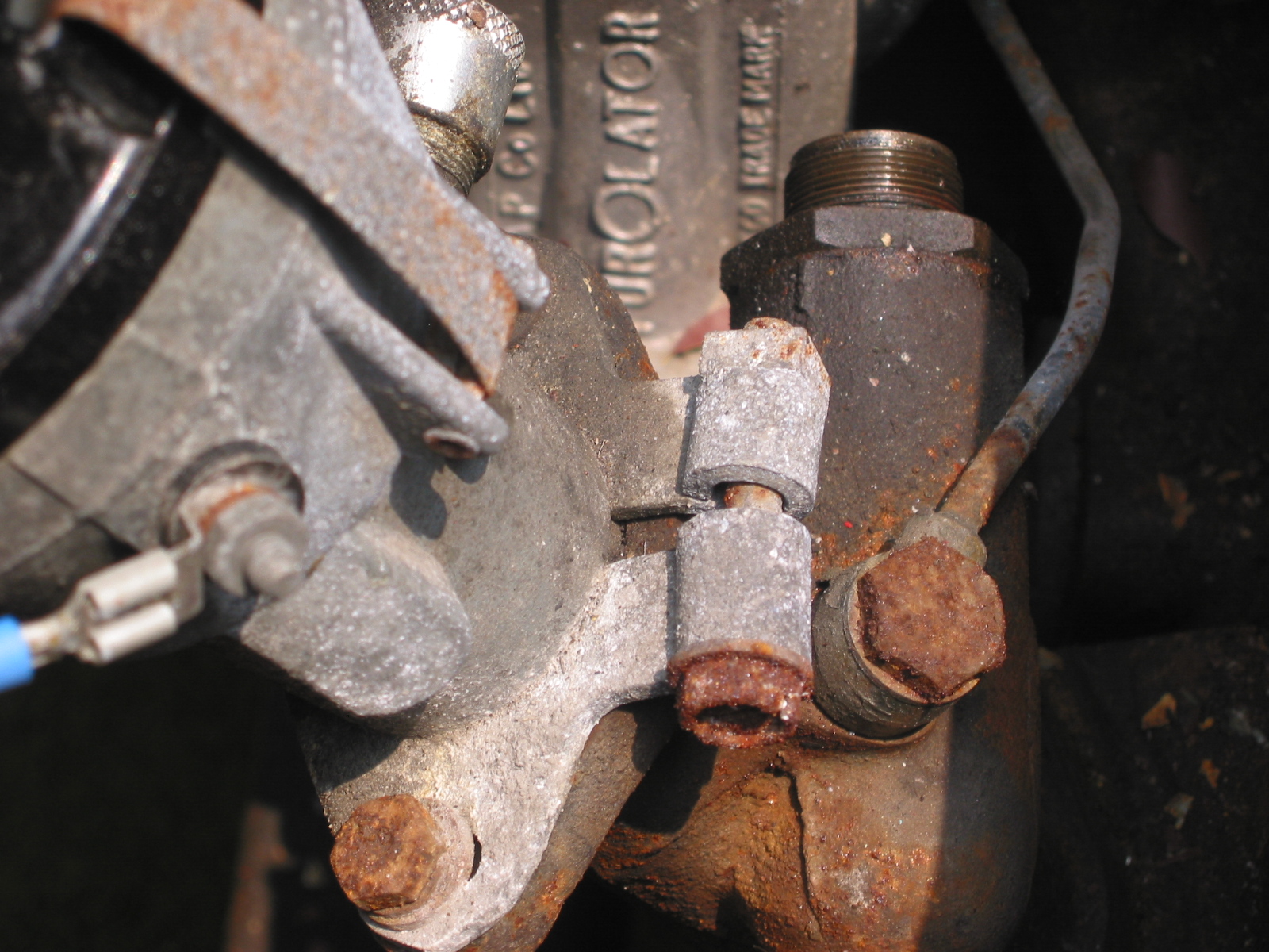
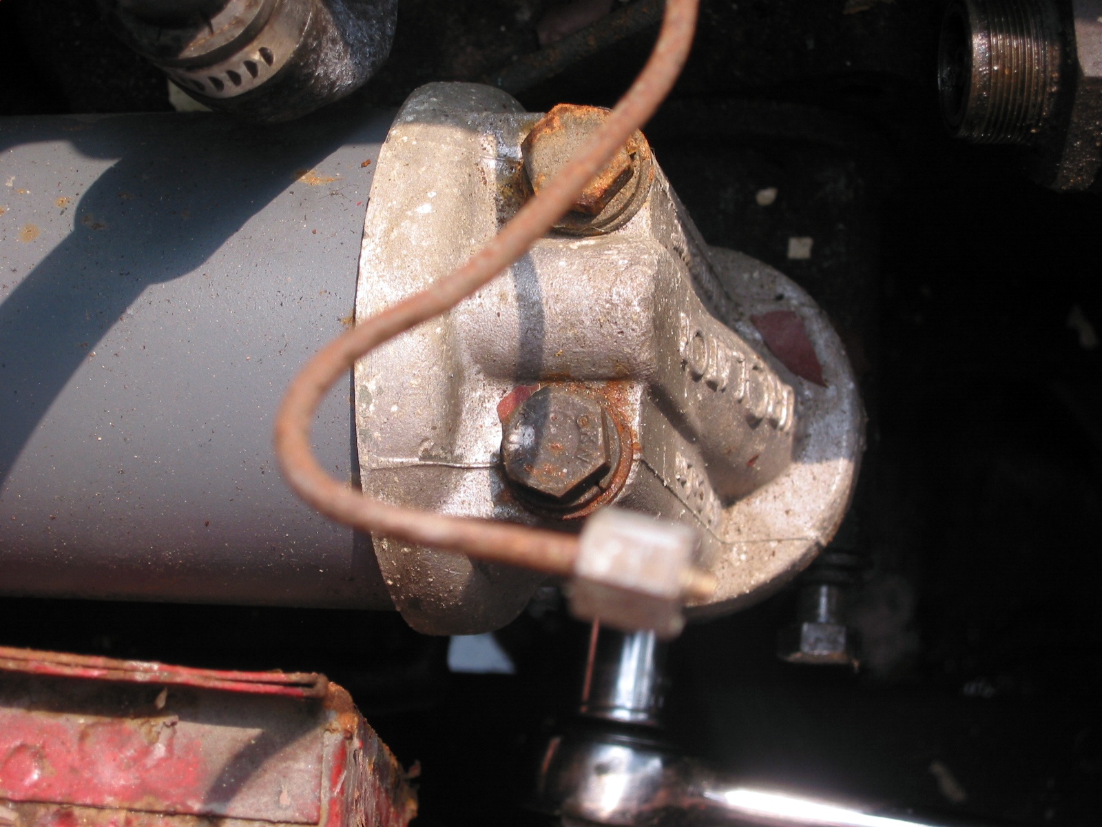
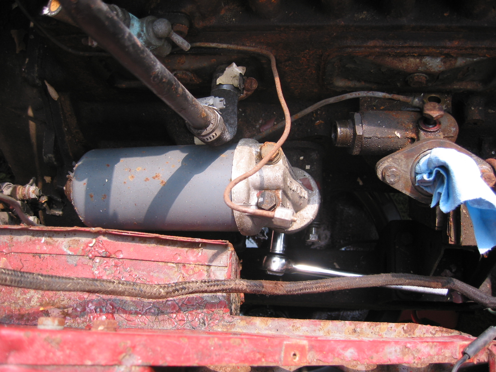
Oil Filter – Removed two large bolts to the engine block.

Oil Filter Mount

Oil Filter
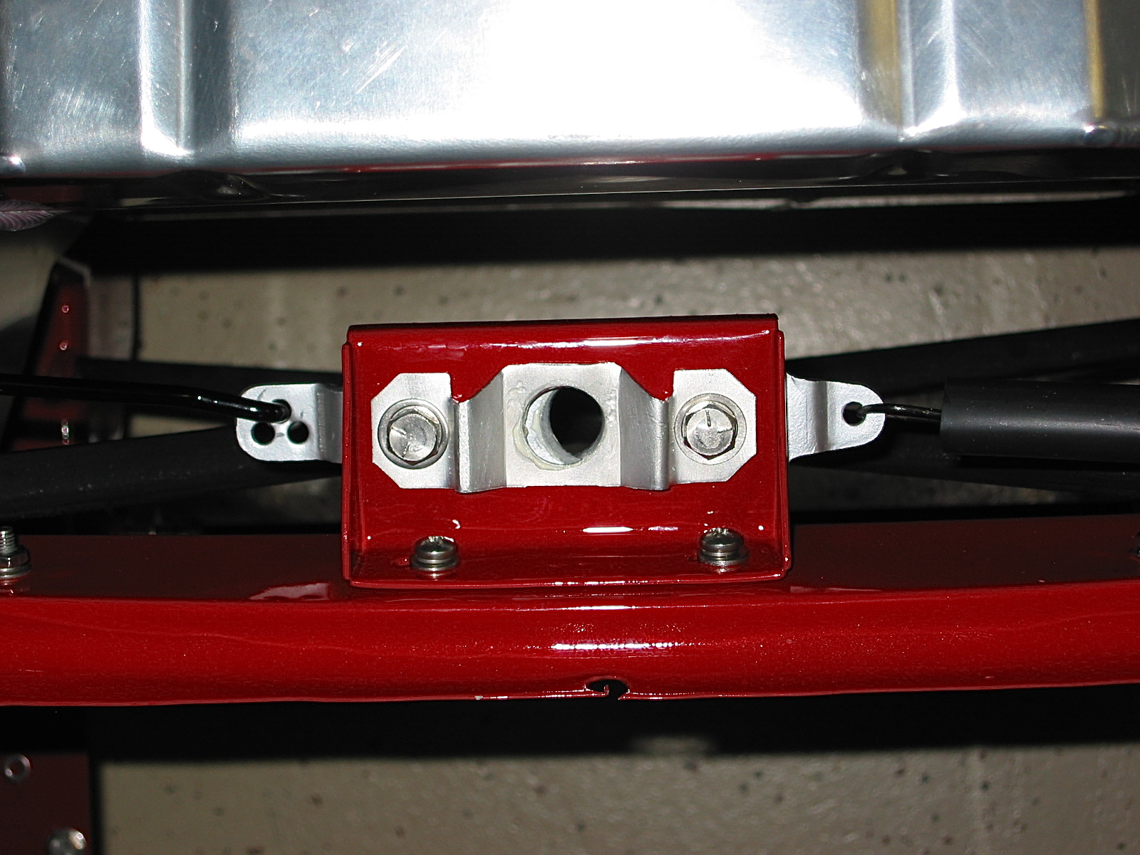
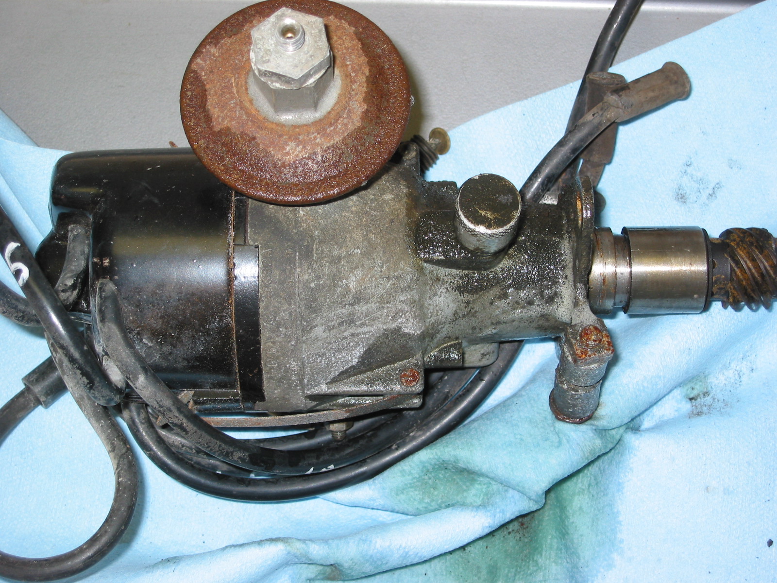
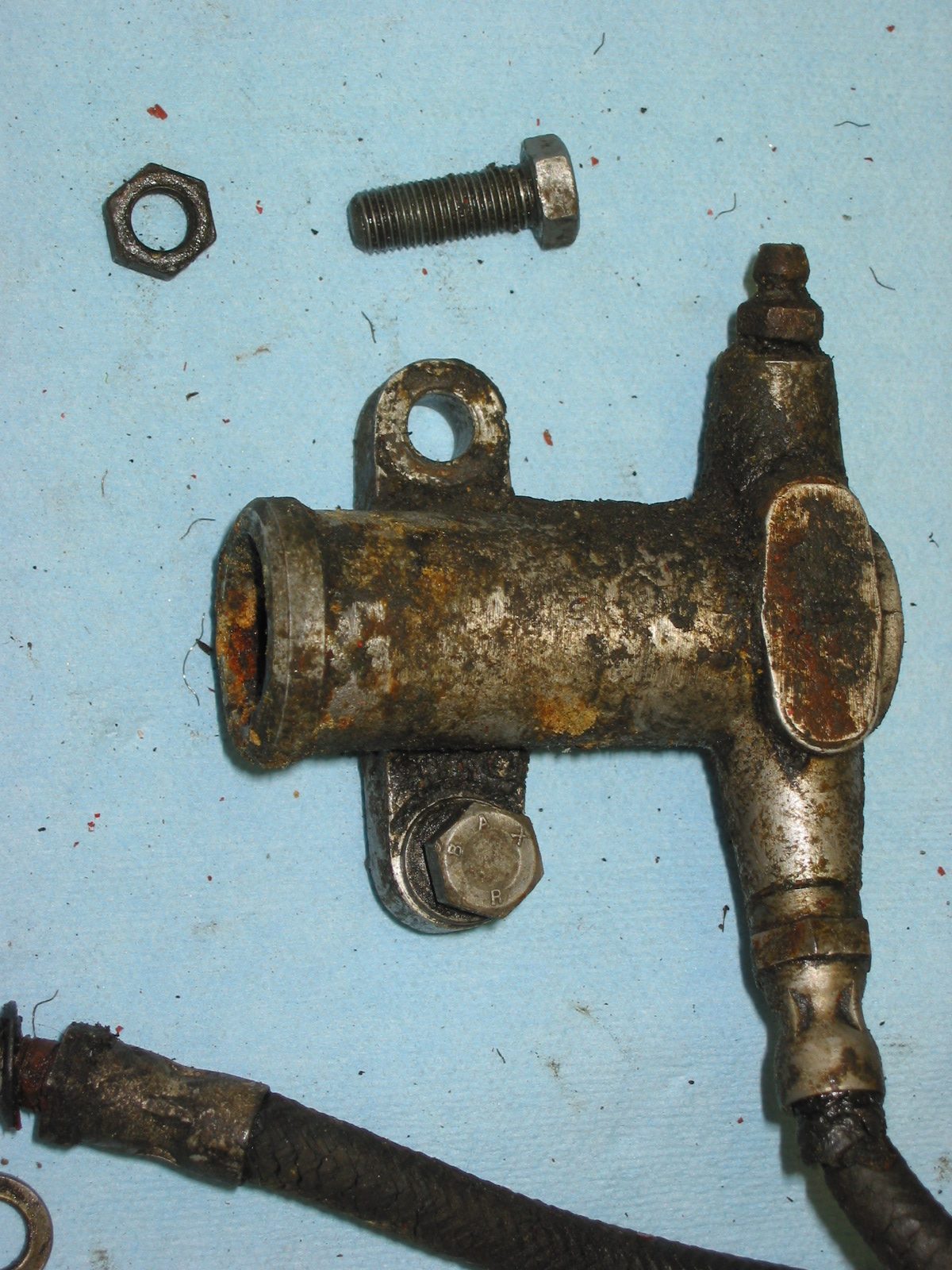
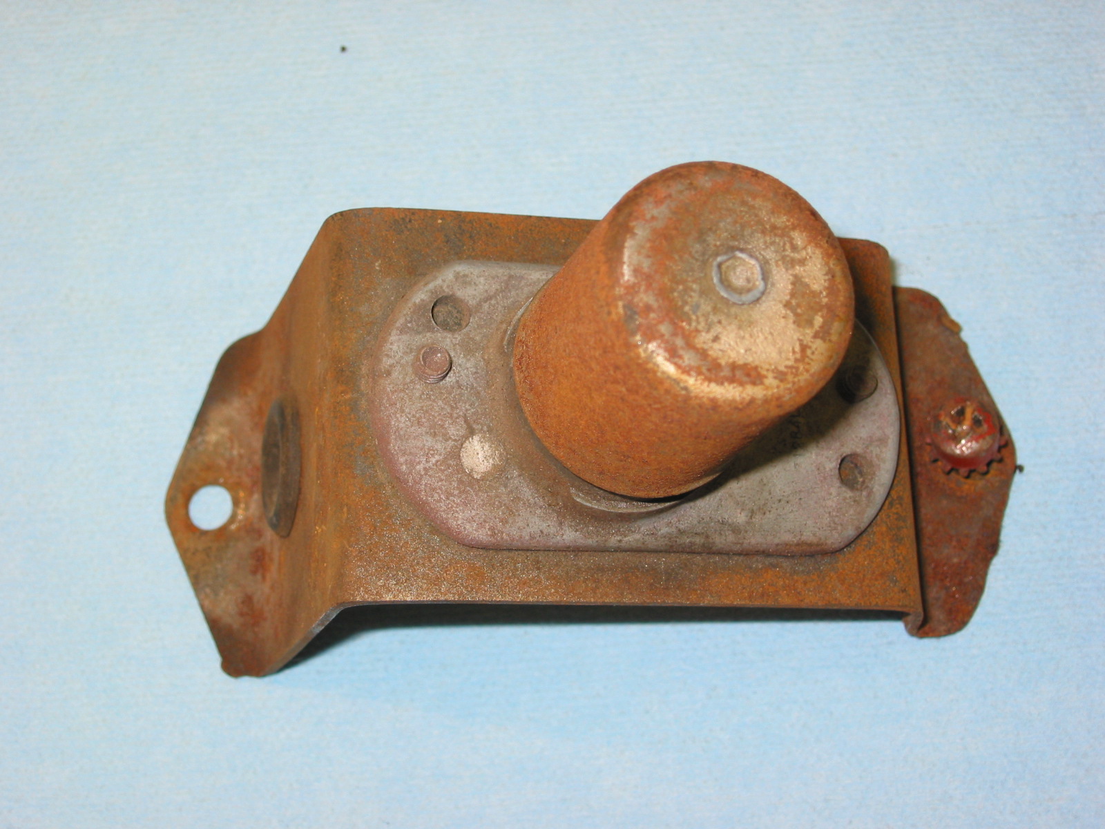
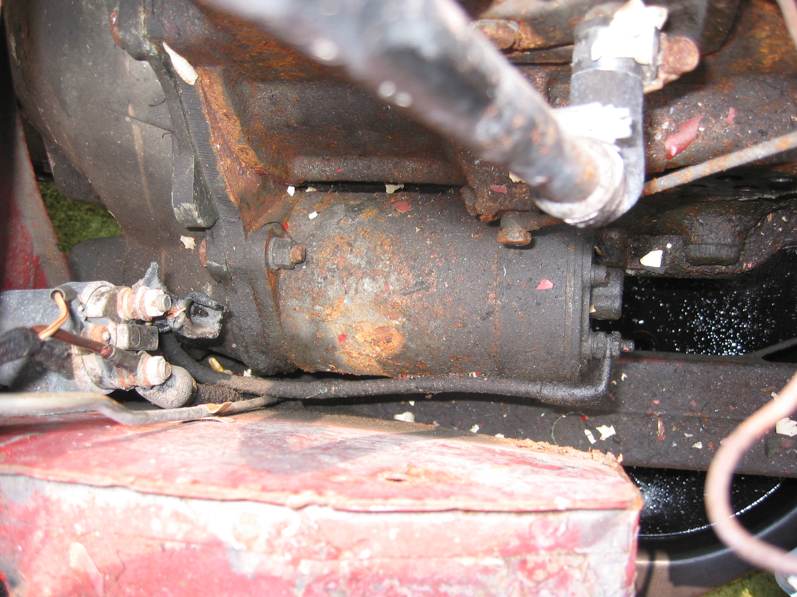
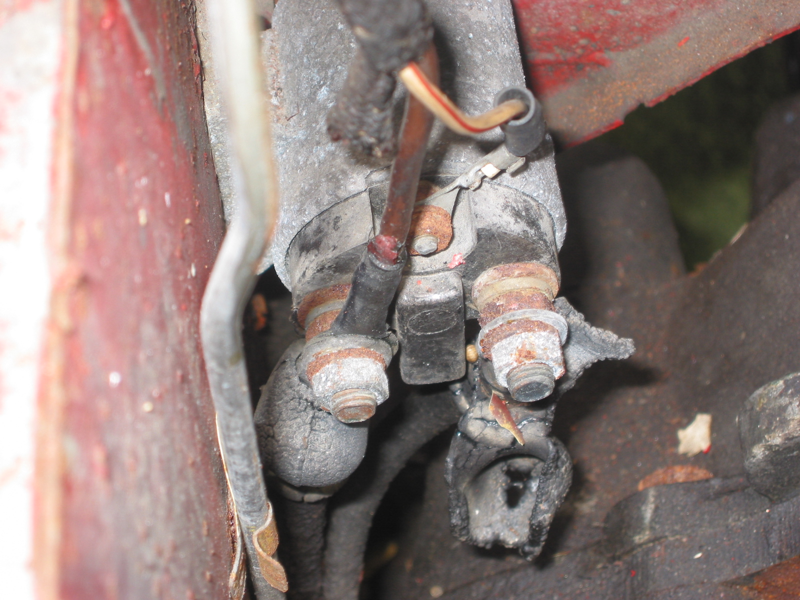
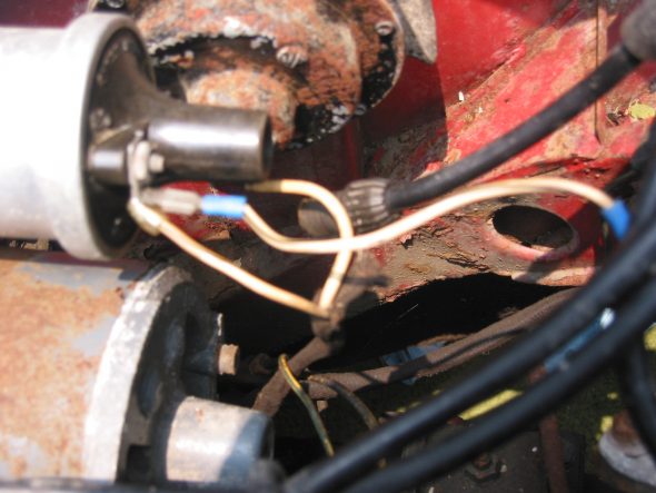
Starter and Solenoid – Disconnected solenoid to starter lead cable. Loosen two 9/16” bolts accessed through the interior bulkhead and under car.

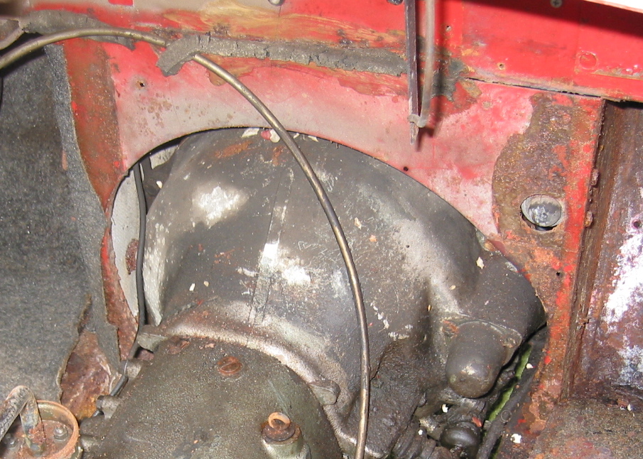
Starter
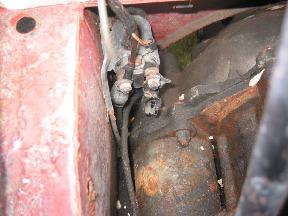
Starter Solenoid

Starter Solenoid Wiring
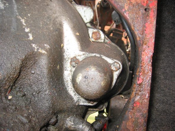
Starter Cover
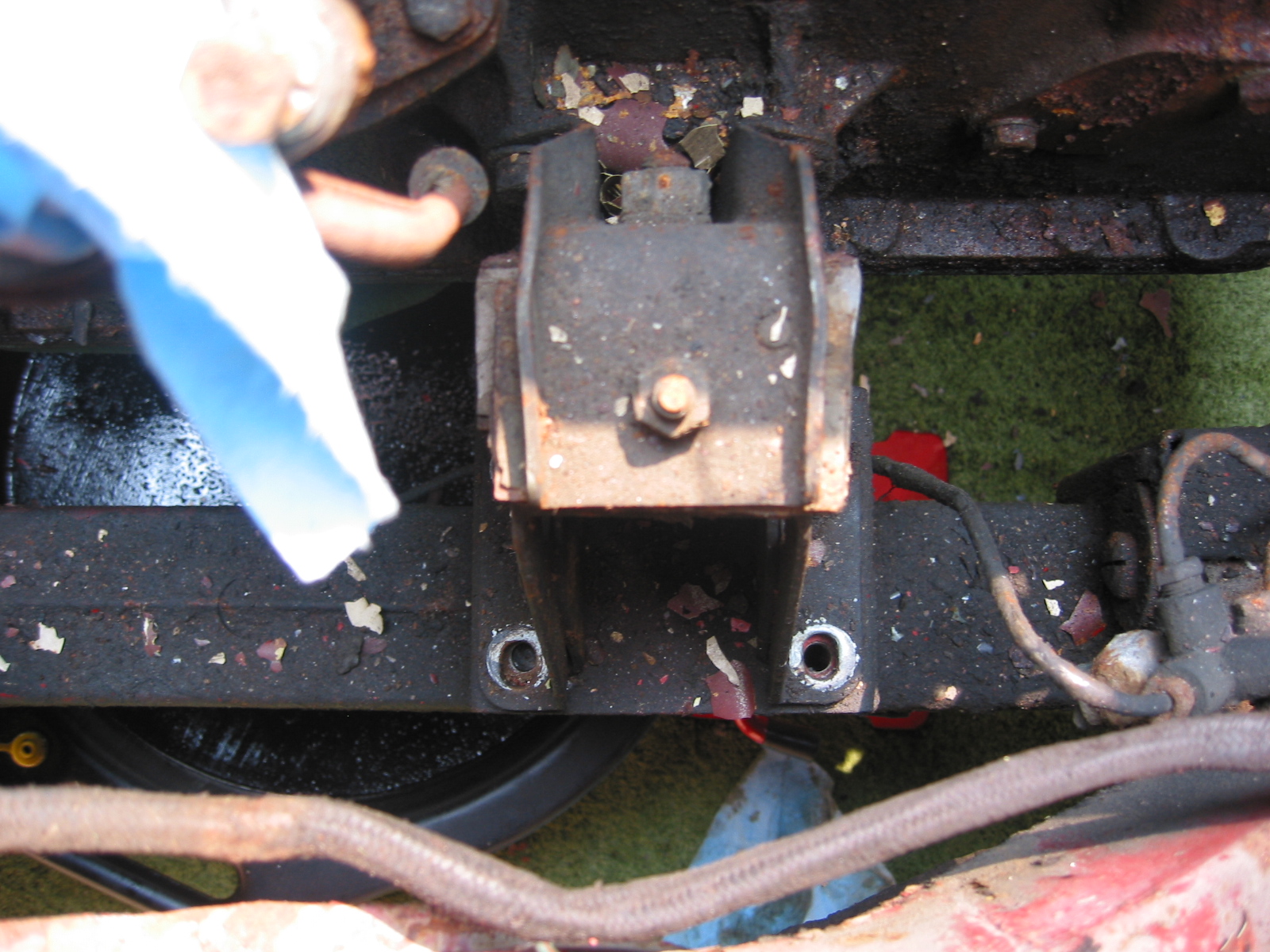
Engine mounts – Removed 4 bolts from right front to frame. Then removed left side.

Engine to frame Mount
Ground strap – Disconnected the strap from the frame.
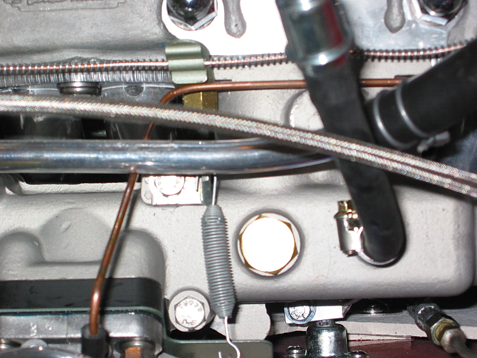
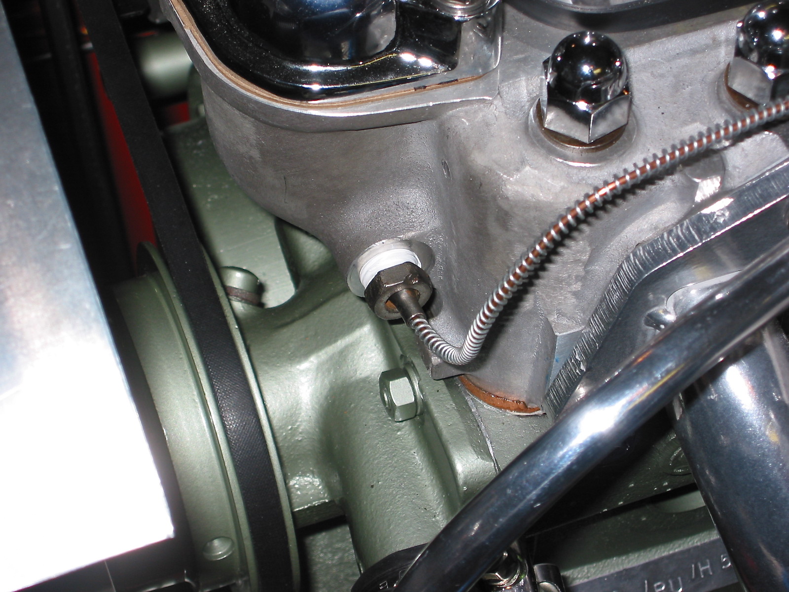
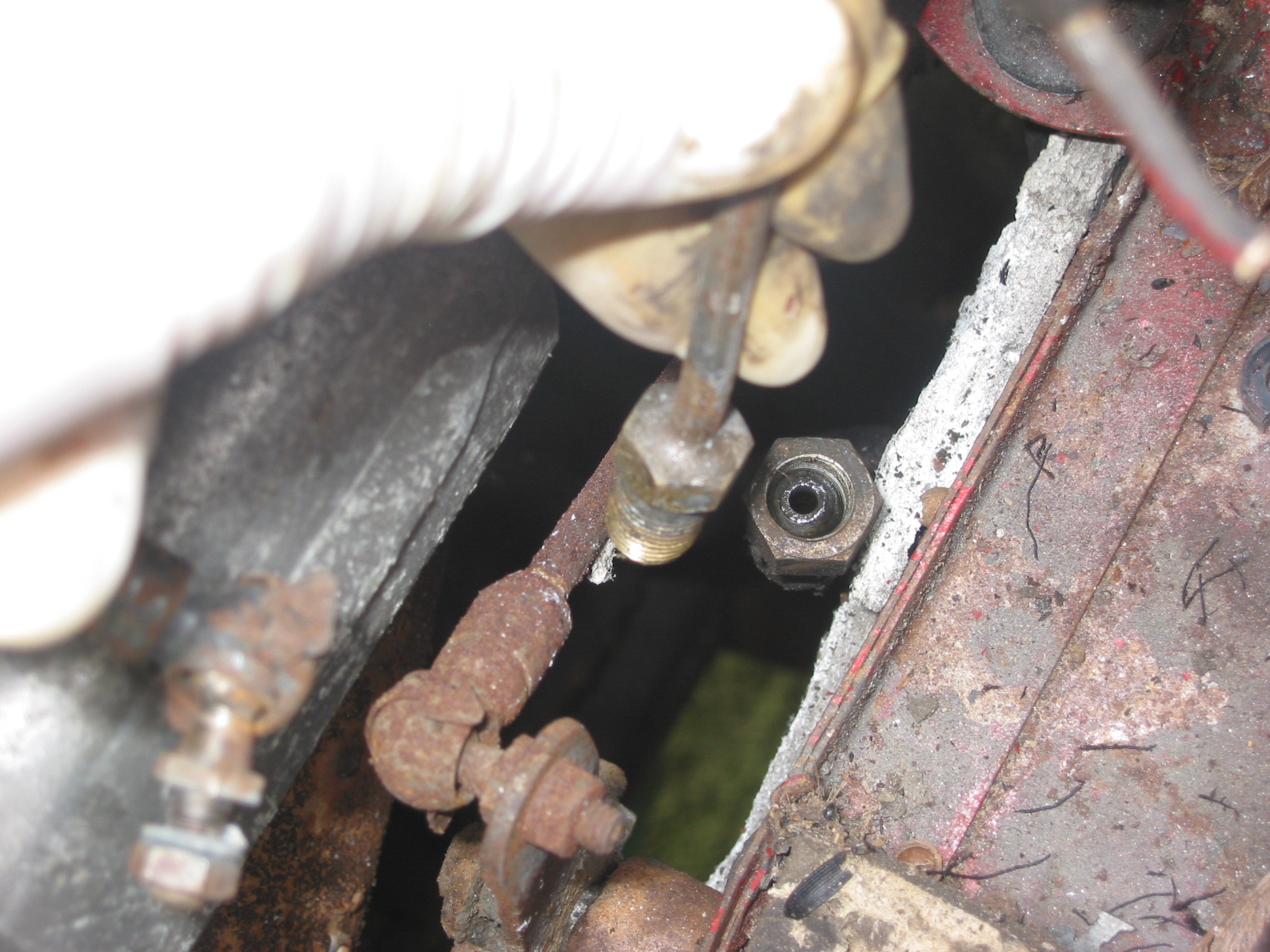
Oil pressure line – Disconnected the line at top union near intake manifold.
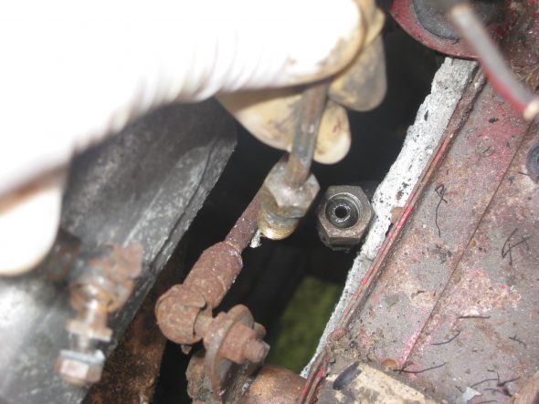
Oil Pressure Line Disconnect
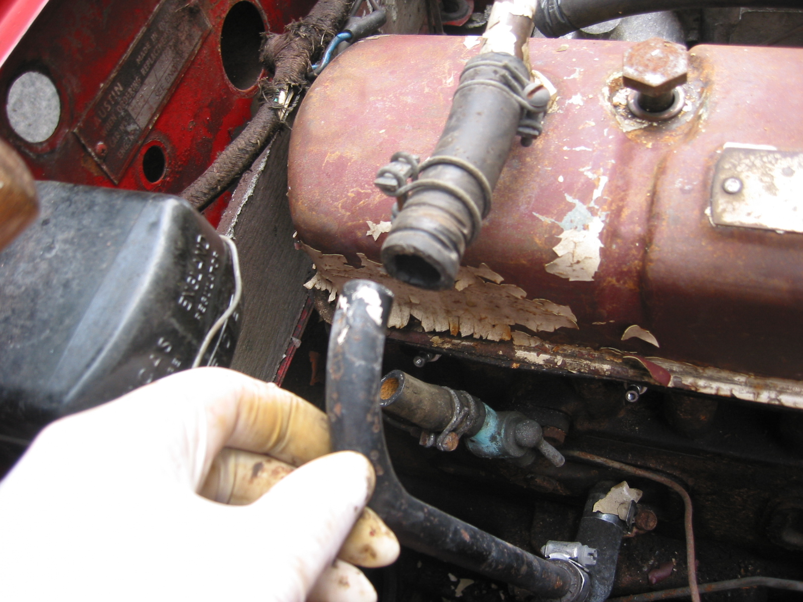
Breather pipe – Disconnected the pipe at the “T” junction on the rocker cover.

Breather Pipe Disconnect