Chapter 13 – Cleaning and Trial Fitting

March 22, 2003

Rear Seats 

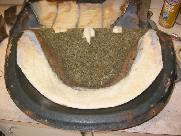
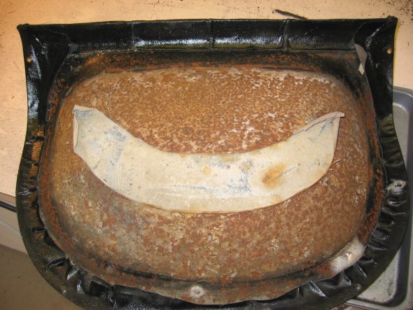
The rear seat pans were very rusty and pitted to some degree, but given that they are completely covered by upholstery we decided to reuse them. The bottom exposed side of the seats was painted with a rubberized undercoating paint. 

Rear Seats 1

Rear Seats 3

May 16, 2003

Canadian Delivery! 

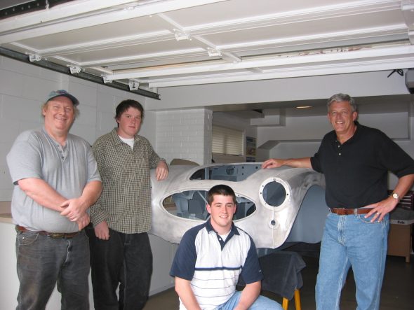
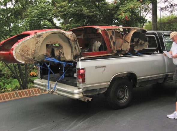
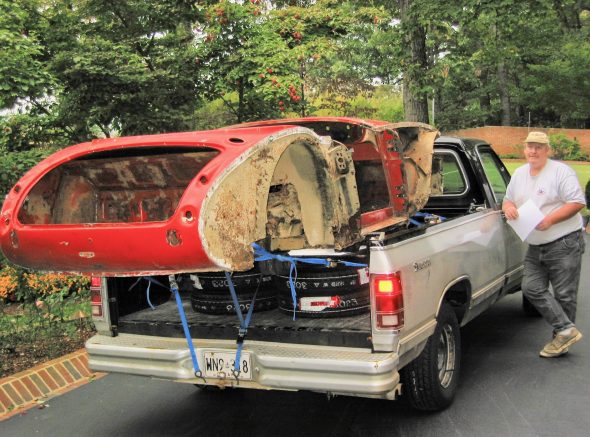
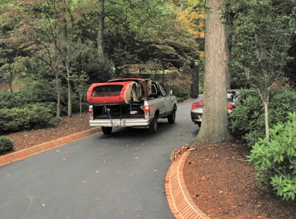
Martin Jansen delivered the healey from his shop in Canada on the back of his pickup truck! Big day!

May 16 Arrival Day from Martin 1

Rough Body 2

Rough Body

Rough Body 3

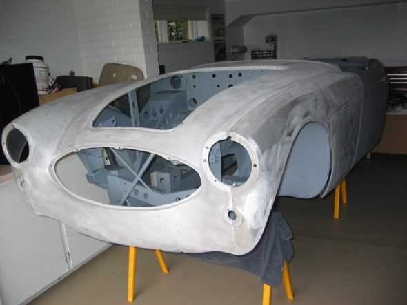
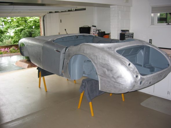
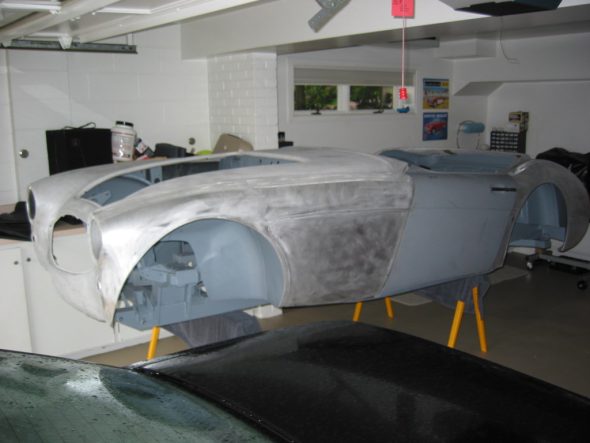
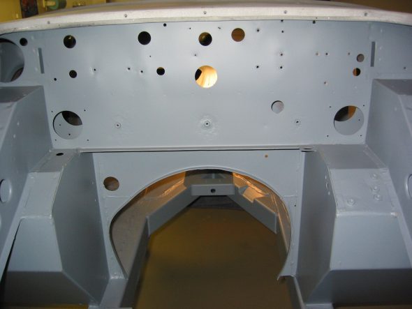
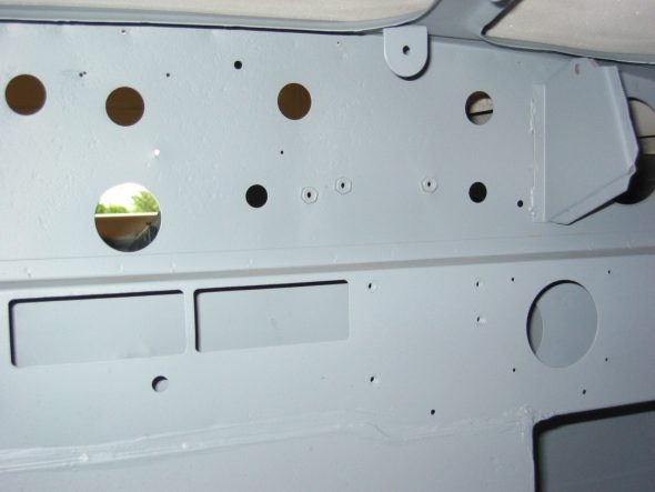
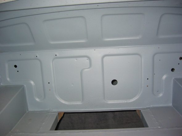
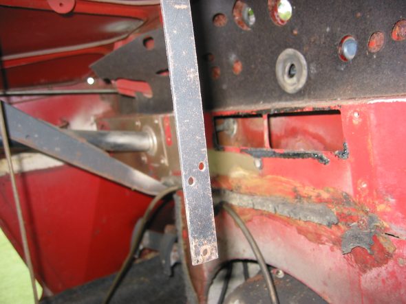
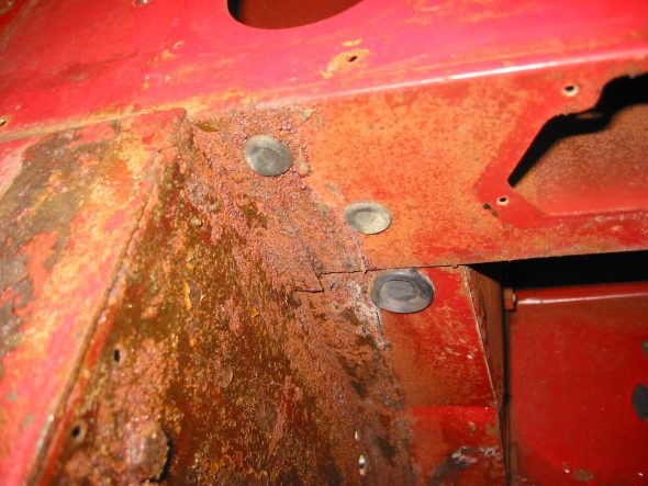
The frame and superstructure looked great. The fit of the wings will have to be improved upon. Door fit is pretty good, but will also need additional work. New edges were put on the rear shroud and rough repairs to the front shroud lower panel were made as well as around the rear shroud taillight area. Seeing the interior panels without rust is hard to believe, but they sure look good now! One disappointment is that mounting holes for a number of things are not located on new panels installed by Martin. Seat rails, exhaust mountings, insulation panels and etc will need to be aligned and drilled.

Firewall 3

Firewall 2

Boot 1

July 15, 2003

Maple Hill Restorations 

After consulting with Jeremy Turner from Maple Hill Restorations we have decided to completely assemble the car while in primer to be ensured that EVERYTHING fits properly. This will prolong the project, and will probably lead to some short term frustration, but should also minimize problems with assembly once body work and painting is complete.

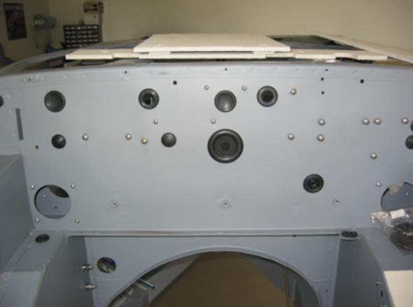
My first step is to determine proper fastener sizes and replace all original hardware with stainless steel, with the exception of higher load locations such as shock absorber and other suspension bolts. Those will be replaced with new grade 8 zinc plated hardware. Then we installed all of the rubber grommets in the firewall, footwell and other locations.

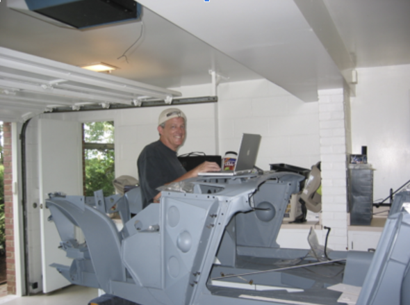
The Scientist at Work

Chased Threads and rubber grommets

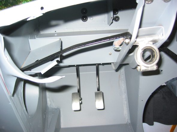
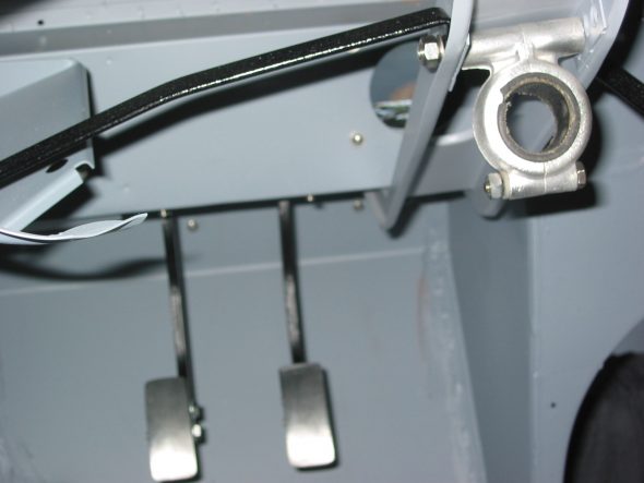
Installed pedal box

Steering Bracket and Brace

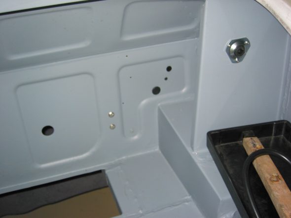
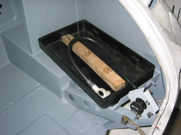
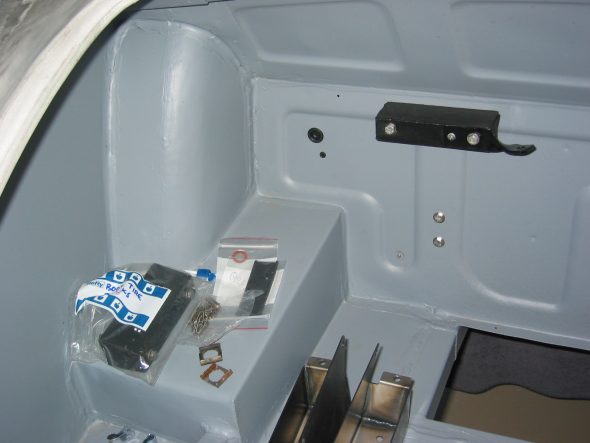
Boot Grommets – The grommet for the battery cable and other bulkhead grommets were installed in the boot. The anti-theft battery switch and bracket were also installed.

Boot grommets

Battery box and switch

Bump Box

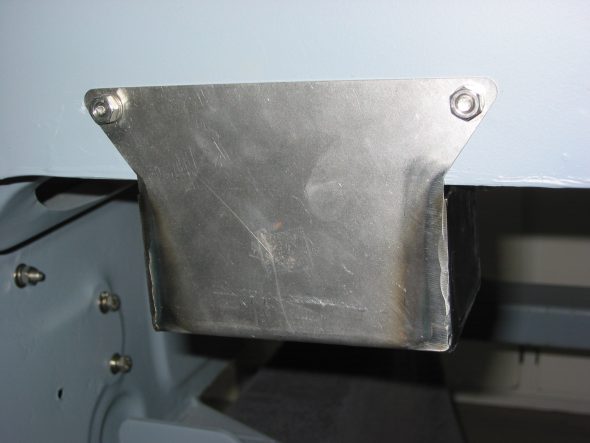
Boot Tire Buffer

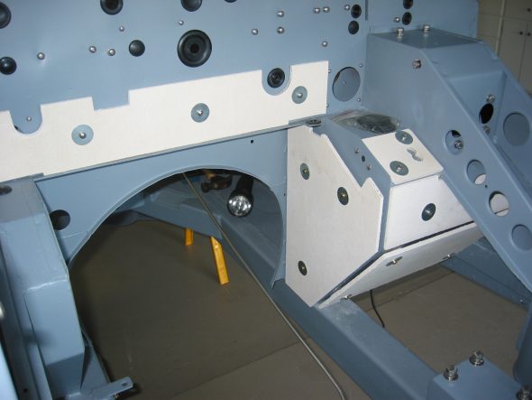
Insulation Panels – Some of the mounting holes for the heat insulation panels on the firewall and footwell were also not drilled. We located the proper locations, drilled the holes and mounted the panels without difficulty.

Insulation 1

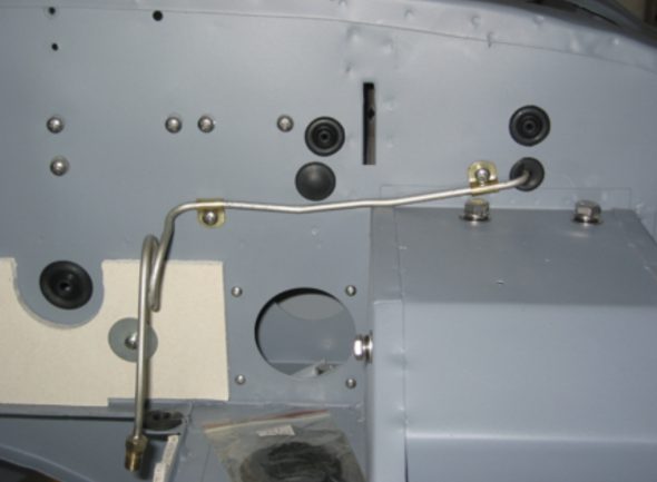
The Oil Pressure Line – The line was located and installed although new clips will be ordered.

Oil Line

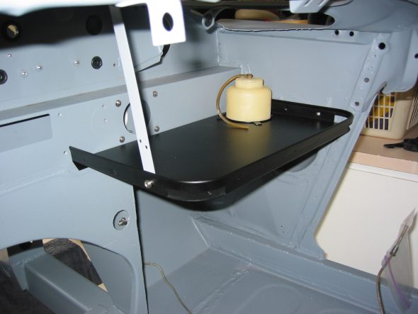
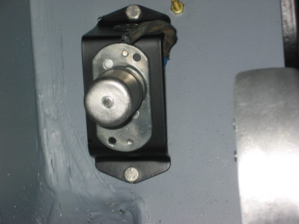
The Dip Switch and Parcel Tray – These components were also located and installed. Note the original water bottle.

Parcel Tray & Bottle

Installed dimmer switch

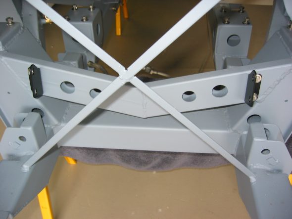
Radiator Brackets – The brackets were cleaned and painted and were installed on the crossmember, and the painted air intake flange.

Radiator Mount 2


July 23, 2003

Hardware Reassembly

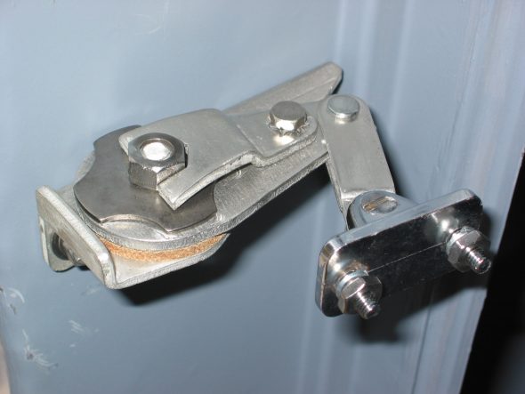
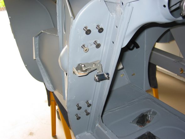
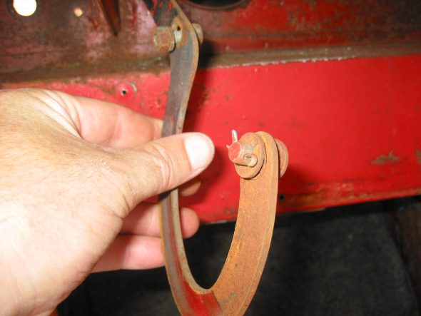
Door Staps – The original door straps (catches) were cleaned, re-zinced and installed on the door pillars.

Door Strap 1

Door Strap 2

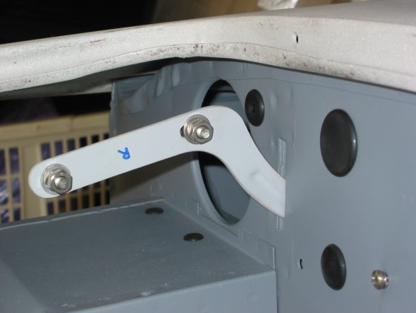
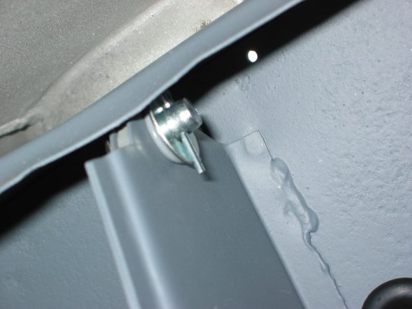
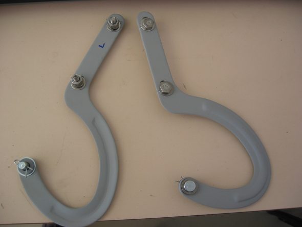
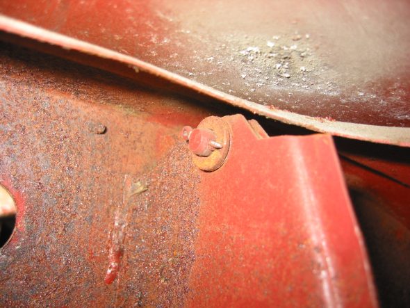
Bonnet Hinges – The bonnet hinges were cleaned, primed and new stainless hardware was installed, and then mounted to the car.

Bonnet Hinge 1

Bonnet Hinge 2

March 22, 2003

More Cleaning 

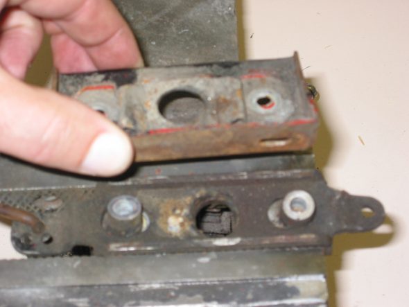
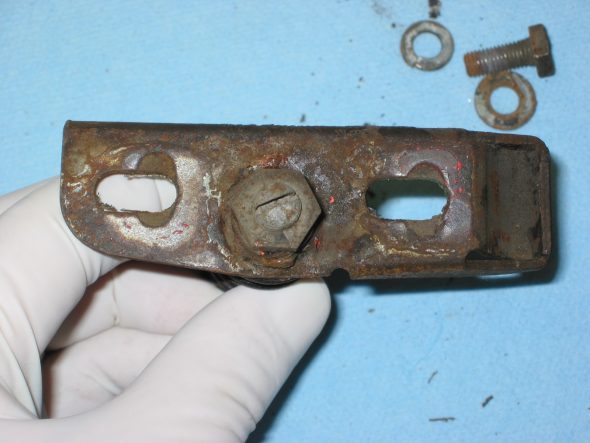
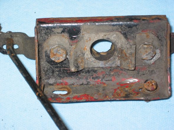
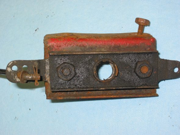
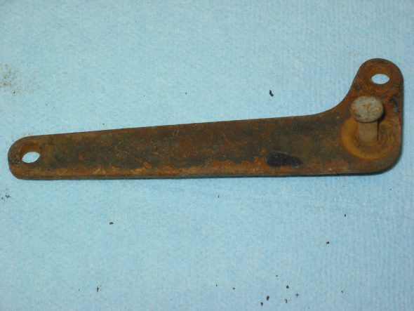
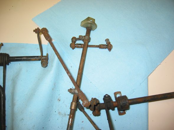
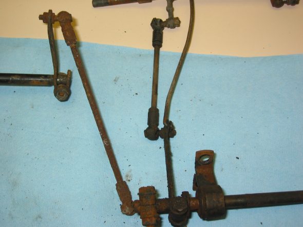
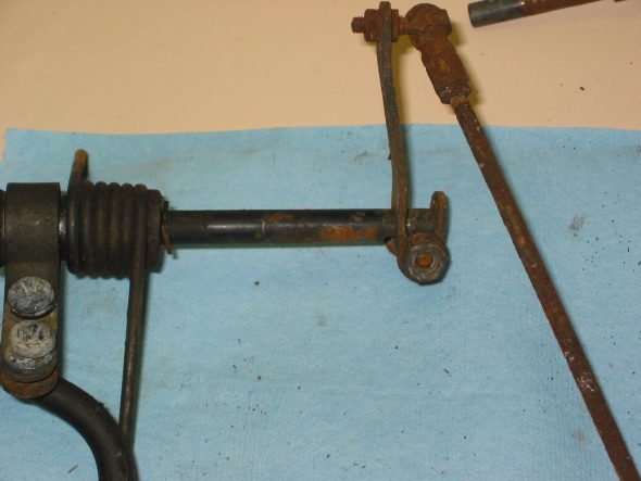
Bonnet Latch Hardware – Disassembled and cleaned the bonnet latch assembly and the bonnet opening rod assembly for Jeremy Turner to media blast and paint.

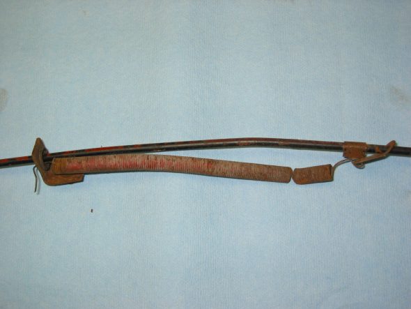
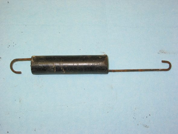
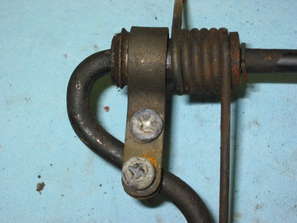
Bonnet Rod Spring

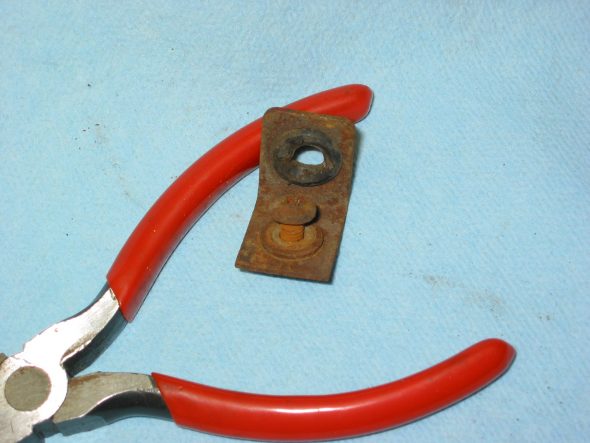
Bonnet Rod Bracket grommet

Bonnet Latch A

Bonnet Latch B

Bonnet Latch C

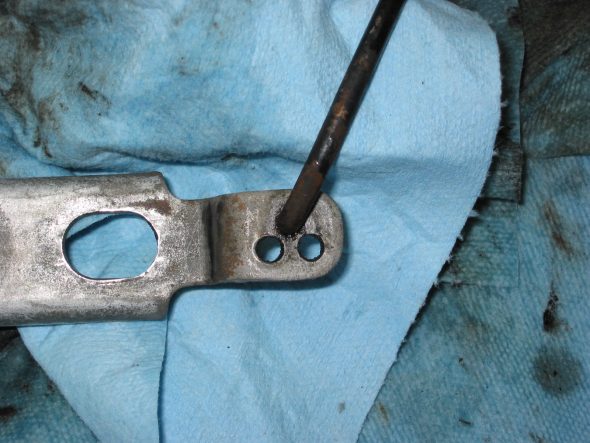
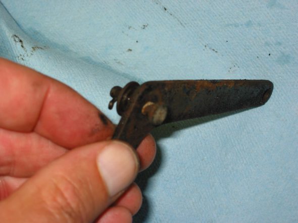
Also cleaned the bonnet rod clip, the catch bracket, two safety latches, the brake reservoir bracket and two shroud brackets.



Chapter 11 – Disassembly

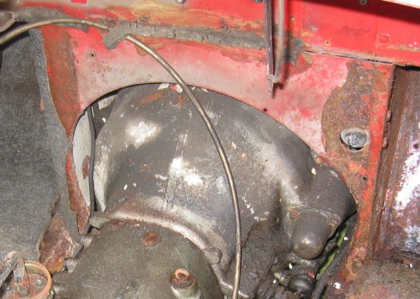
The Battery Cable –  from engine to boot. Eight to nine clips attached with screws to frame.

October 20, 2002

Shipping to Jule Enterprises

Martin Jansen – from Jule Enterprises located just outside of Toronto picked up the car for the trip back to Canada for frame replacement and restoration. John, Scott and I had visited his shop in Canada earlier in the summer to “check it out.” We were pleased with what we found and I arranged for Martin to pick up 4422  for restoration work.

Martin Jansen Picking Up the Healey 10-20-2002

Martin Jansen Picking up the Healey 10-20-2002 2

Martin Jansen Picking up the Healey 10-20-2002 3

Martin returned to Canada with the primed doors and four new aluminum wings to be fitted before bringing the BT7 back to Harrisonburg. In addition to fitting the old tub to the new Jule frame, he will media blast the body, epoxy primer the car, add new aluminum flanges to the rear shroud, and do rough repairs to shroud damage on the front and left rear. We anticipate a return date around the first of February. Lots of parts to clean between now and then.

November 9, 2002

Bonnet Hinges – After a very busy work month, this weekend provided some time to return to parts clean-up and restoration. Cleaned a primed both bonnet hinges and added stainless hardware.

Cleaned and primed Bonnet Hinges

Door Check Strap Assembly – Both door strap catches were cleaned. The Moment-Anderson Restoration Book states that these straps have a zinc plated finish rather than paint. The straps will need to be refinished at a later date and new washers added.

Cleaned Door Catches

November 17, 2002

Rear Axle

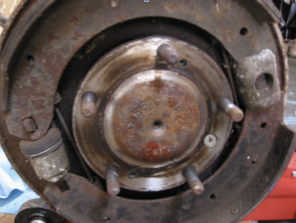
Rear axle disassembly –  Removed five lug nuts and the rear splined hub. Then loosen two Phillips head screws securing the rear brake drum and remove the drum.

Brake Drum Hub Nuts

Rear Axle Half Shaft

Removed the brake shoe retaining springs and slipped off the lower shoe. Disconnected the handbrake tension spring to release pressure and slipped off the upper shoe.

Removed the shoe adjuster by loosening two 9/16” nuts and knocked out. Note shape of pistons. Remove axle by loosening one 3/8” flat head phillips screw. Note paper gasket. Pull out axle half shaft. The left and right shafts are marked with an engraved “R” or “L,” because they need to be replaced to the original locations.

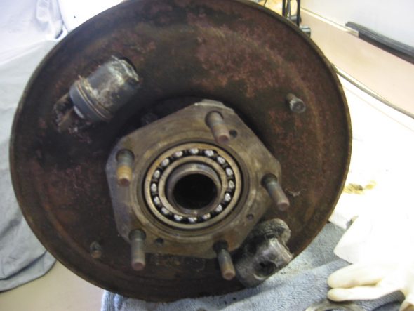
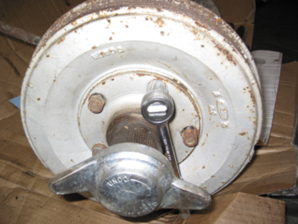
Rear Hubs – Removed the octagonal nut retaining the hub. One of the nuts loosens clockwise and one counterclockwise. Remove the O Ring, flat washer and retaining band. Remove the back plate by loosening 4 nuts and bolts. The bolt heads face the outside of the car. I ordered a special socket from BCS for this purpose.
left rear hub – nut removed

Shock Absorbers – Removed the rear shock absorbers by loosening 11/16” nut and kncked pin through the bushing and out of the bracket holding the shock.

Rear Differential – Removed rear differential from axle by loosening 12 nuts and lock washers. Top center bolt also retains the brake line clamp.
November 29, 2002

Rear Hubs

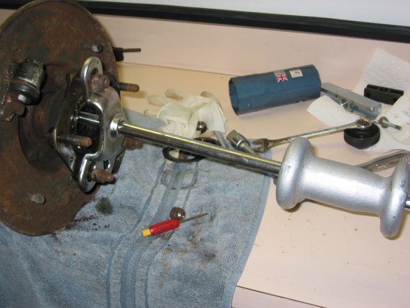
Left Rear Hub – Used a slide hammer to loosen and remove the hub from the axle.

Hub removal-too Slide Hammer

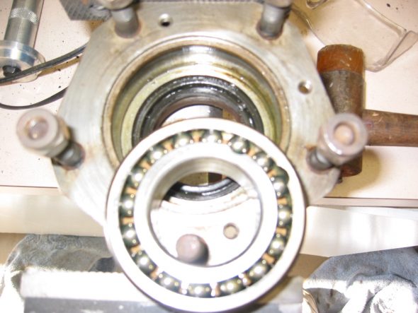
After the hub is removed the bearings can be knocked out with an appropriate tool.  The “made in England lettering is to the outside of the wheel. The paper gasket, and rubber “O” ring are removed as well. The hub also includes a rubber seal on the inside of the hub. I could not remove it, will have to learn the secret!  Later learned the secret is a screwdriver. The left hub nut loosens “clockwise” and the right “counterclockwise.”

Rear bearings

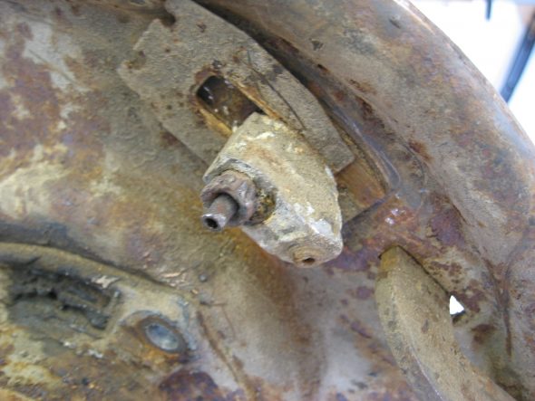
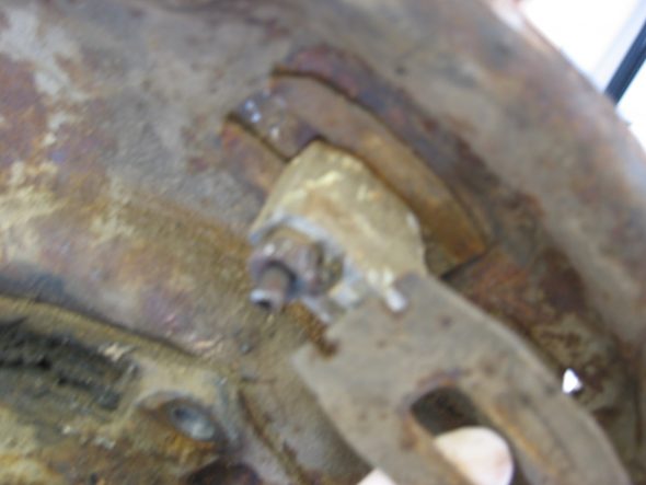
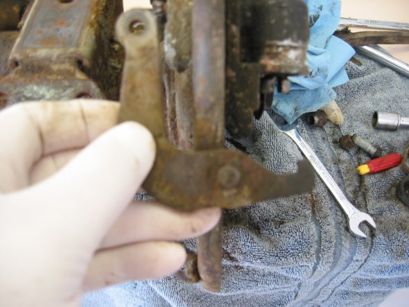
Brake Cylinders – Pulled off the retaining circlip from the rubber boot on the wheel cylinder. Remove the rubber boot cover and the rubber gasket from around the cylinder assembly. Pry apart the sliding plates that lock against one another. The lockplate with the tabs “up” goes against the backplate and the one with the open slots on the top. After removing the lower plate slide out the handbrake lever. Then take off the inside lockplate and remove the cylinder.

brake cylinder retainer clips

Brake cylinder retainer clips 2

handbrake lever

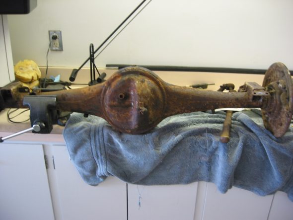
Shoe Adjuster – by loosening two nuts, note the position of the adjuster piston. Remove backplate by loosening the four retaining nuts and bolts. Finally, clean up the rear axle.
rear axle clean up

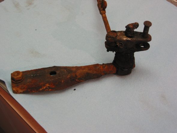
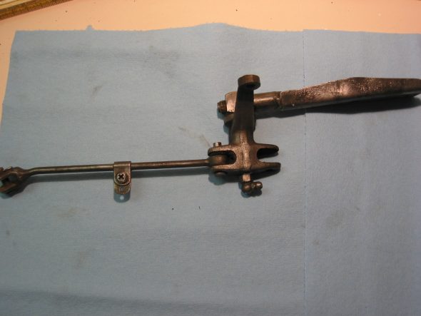
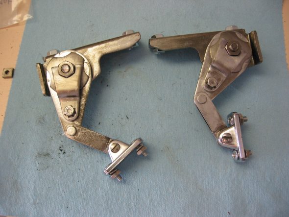
The handbrake lever assembly –  was removed, disassembled and cleaned. Note the replacement of the cloth/rubber “O” ring under the large nut, and felt washers at the connecting pins. The bracket itself can be removed by loosening two 5/16” – 24 x 3/4” bolts and nuts. The mounting clip for the return spring is located 2 1/4” from the post.
handbrake bracket 1

Handbrake Bracket 2

Handbrake spring location

Handbrake Bracket 4

January 25, 2003

This report is the first of my second year of working on the restoration of 4422! Lots of work remains in the disassembly and clean up stage before reassembly can begin. But progress has been made!

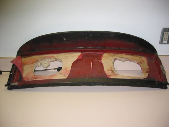
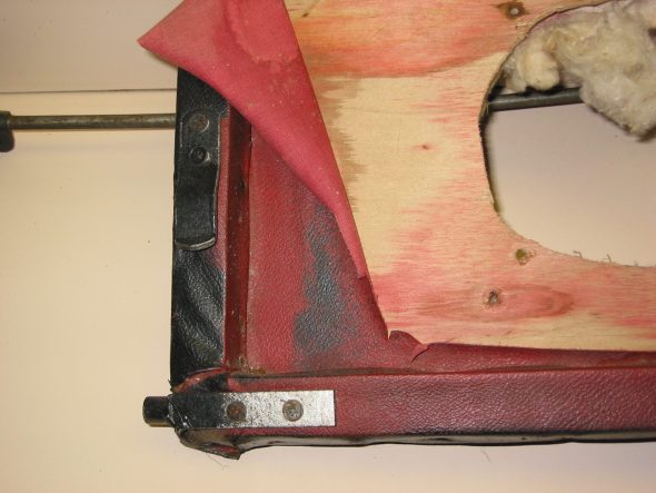
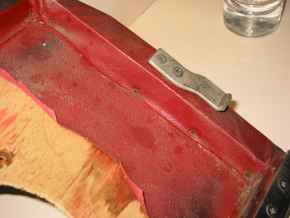
Rear Seat Back  

Unfortunately, I had installed speakers in the panel when in college. So I will need to buy a new squab or at least the plywood flat pieces before recovering.

Rear Seat Back Panel 1

Rear Seat Back Panel Clips

Rear Seat Back Panel 2

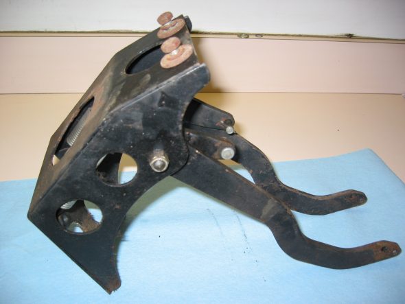
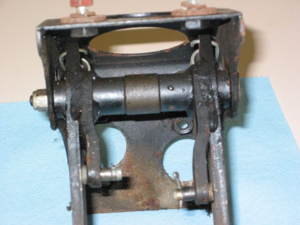
Clutch and Brake Pedal Bracket (Pedal box) -The box and parts were in very good shape. It was now time to disassemble and clean.

Pedal Box Assembly

Pedal Box Assembly 2

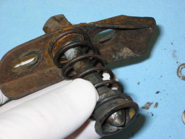
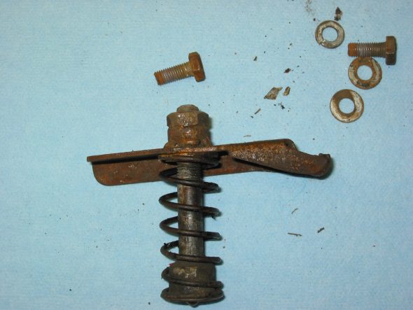
Striker pin assembly – The bonnet catch was a bit rusty, but restorable.

Bonnet Catch Striker Assembly 1

Bonnet Catch Striker Assembly 3

Bonnet Catch Striker Assembly 2

The Bonnet Latch Support Bracket – the mechanism was rusty also, but again, clean up made the parts usable.

Bonnet Latch 3

Bonnet Latch 4

Bonnet Latch Lever

Bonnet Latch Spring & Rubber Tube

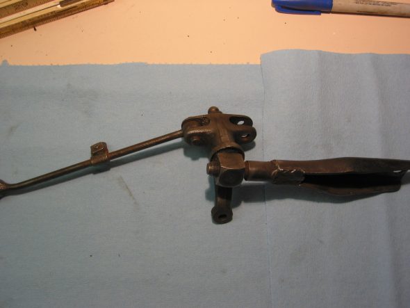
The Throttle Linkage – is also reusable after cleaning, but we will probably replace with new hardware or a contemporary cable system.

Throttle Linkage 5

Throttle Linkage 3A

The accelerator pedal – the pedal and bushing and springs looked great. A little clean up and paint and it will be like new.

Throttle Linkage 2

Accelerator Pedal

Chapter 5 – Disassembly

June 29, 2002

Final Interior Dismantling

Gearbox tunnel and extension cover. Both were rusted badly and were discarded. I learned later as I was fitting new parts that I should not have violated the restorer’s rule: Never throw anything away until the project is complete!

Gearbox tunnel and extension cover

Fresh Air cover plate and screen on left (driver’s) side. Three self threading screws.

Parcel tray on passenger side. Four self tapping screws on the firewall. Three self tapping screws on the right side wall. One screw and nut into left side to hanging support bar. Then removed the parcel support bar with one screw and nut at top.

Parcel Tray Support brace.

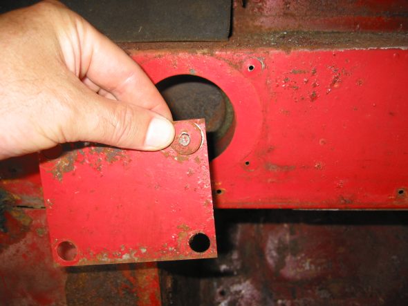
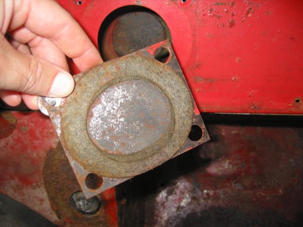
Steering Wheel Shaft Blanking Plate on the right side. Note larger “painted washers” and self tapping screws. Felt gasket found on reverse side of the plate.

Steering Wheel Blanking Plate

Steering Wheel Shaft Blanking Plate Felt Gasket

Two Blanking Screws into captive nuts in firewall on passenger side that just fill holes similar to the driver’s side. These were not painted.

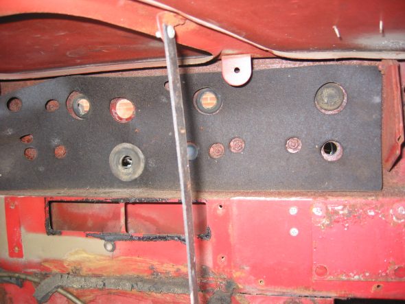
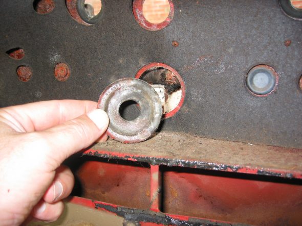
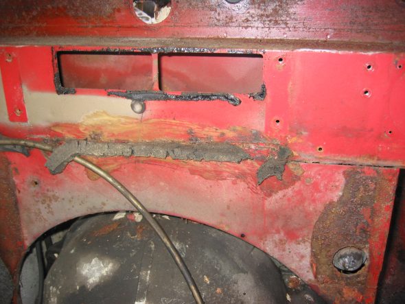
Large Wiring Harness Rubber Grommet in center of firewall. Then removed firewall tarpaper in center of firewall. Note the rubber insulation around the heater box hole and along the seam that would otherwise leak air.

Heat Insulation (tar paper) on firewall

Firewall Grommet

Heater Channel Opening

Center Panel Firewall “Tarpaper.” After removing the firewall “tarpaper” that is in three pieces I numbered the holes:

#1 – Bonnet release rod grommet

#2 – Blank Cover grommet

#3 – Grommet

#4 – Brake Line clip

#5 – Grommet

#6 – Grommet

#7 – Nut

#8 – Nut

#9 – Brake Line Clip

#10 – 1 Nut, 2 grommets Wiper motor

#11 – 2 Nuts

#12 – Nut

#13 – Nut

#14 – Nut

#15 – Nut

#16 – Main wiring harness to dash

#17 – Blank Cover Grommet

#18 – Nut

#19 – Nut

#20 – Nut

#21 – Grommet 

Left Panel Firewall “tarpaper”:

#22 – H2O temp. line

#23 – Oil line

#24 – Nut

Small Blanking Rubber Grommets under the heater opening in firewall. 

Blanking Rubber Grommets

Right Bonnet Hinge cotter pin and 4 washers. The thin washers go closest to the hinge. The nuts go to the inside of the bonnet.

Bonnet Hinge Fixing

Bonnet Hinge

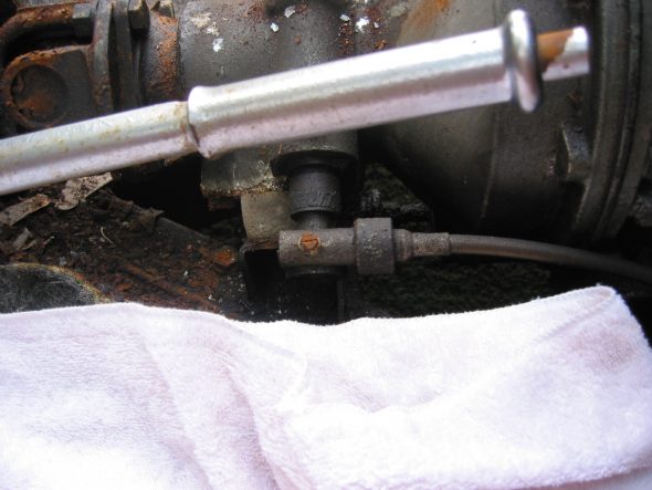
Speedometer Cable at “L” junction to the gearbox.

Speedometer Cable to Gearbox

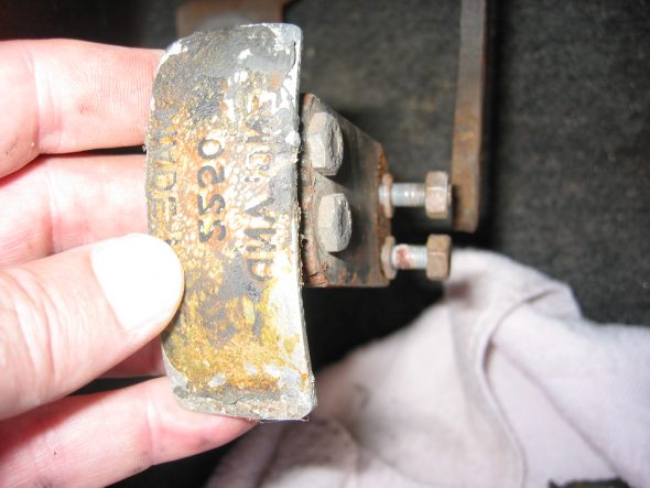
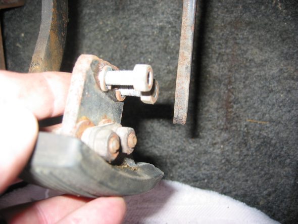
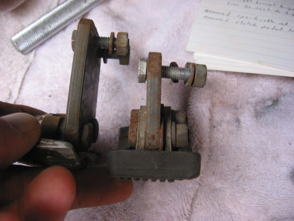
Clutch Pedal from pedal bar – two nuts. The nuts go to the right side. Removed the Brake pedal from pedal bar – two nuts with nuts to the right side. I noticed at this point that some primatively cut spacers had been added to the pedals for a short-legged driver!

Clutch Pedal

Clutch Pedal Spacer

Pedal Spacers

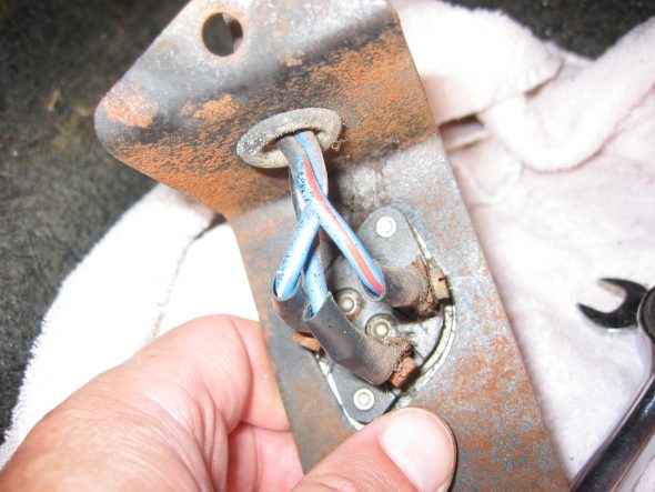
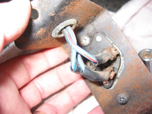
Floor Dip Switch with two bolts to the fixed nuts in floor. 3 wires: red/blue, blue/white, all blue.

Dip Switch Wiring and Bracket

Dip Switch

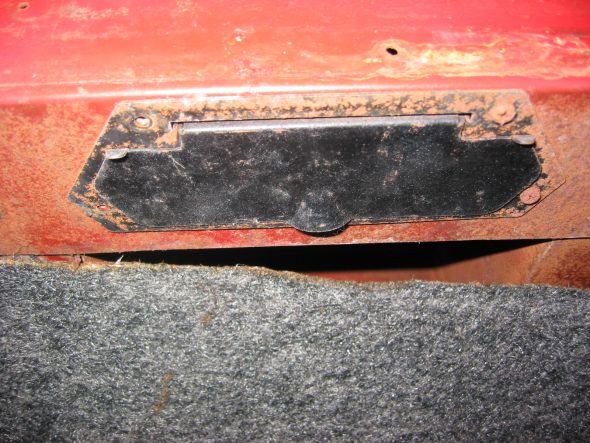
Heater Vents on both driver and passenger side below dash. Four self tapping screws in each

Heater Fresh Air Vent Door

July 2, 2002

Engine

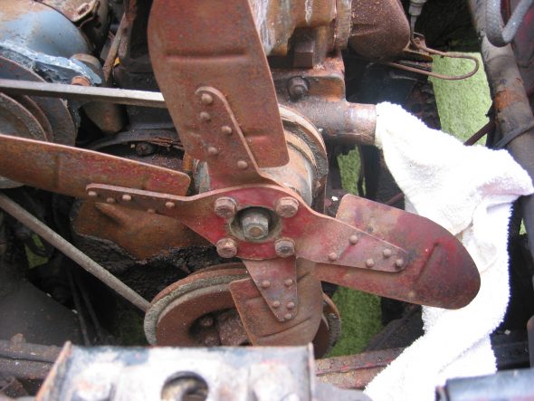
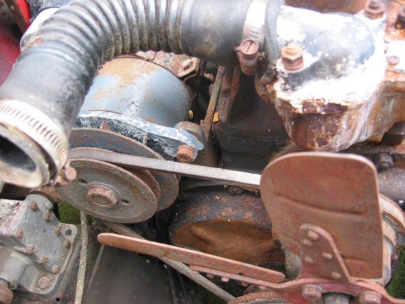
Fan and fan belt – Loosened 4 bolts and washers and removed the fan and fan belt.

Fan and Fan Belt

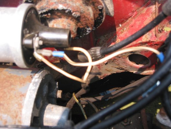
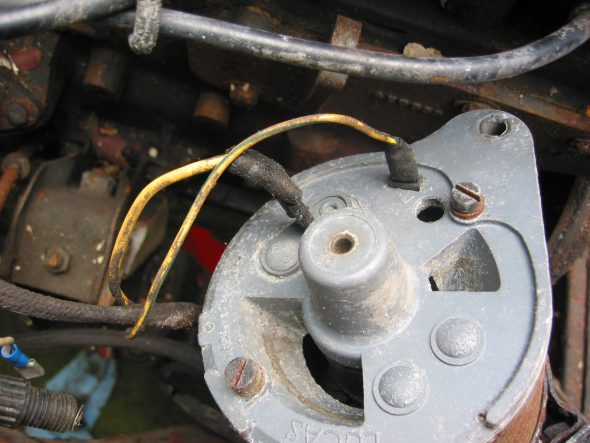
Wiring to the coil –  CB Terminal – White with black stripe from/to the distributor body and white with black stripe from harness that goes to the generator. SW Terminal – Large solid white wire from harness to generator.

Coil Wiring

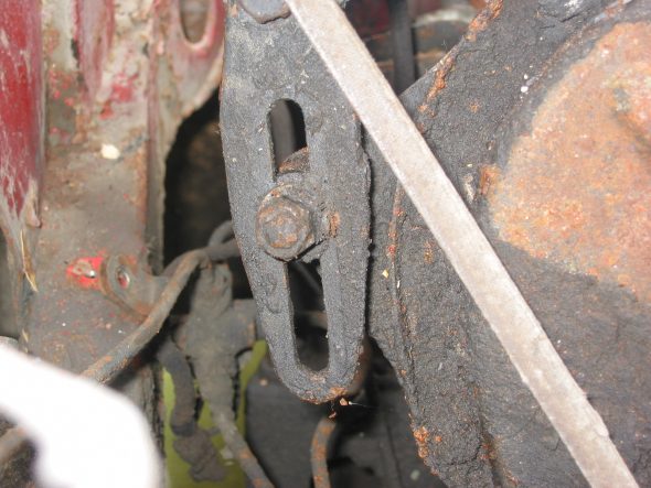
Generator – Removed 2 bolts and nuts and adjusting bracket with self-locking nut. F Terminal – yellow/green stripe wire from harness. D Terminal – Large solid yellow wire connected to large spade.

Dynamo – Generator

Generator Adjustable Mounting Bracket

Generator Wiring

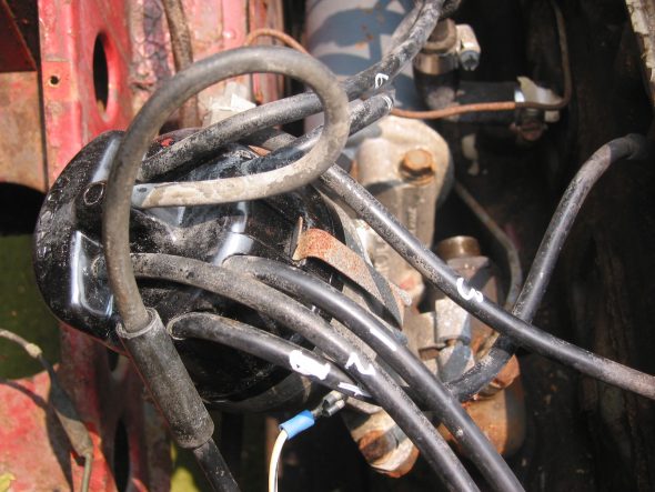
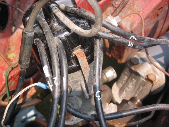
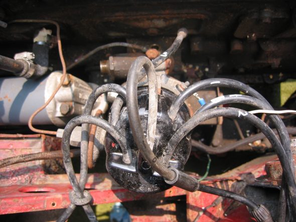
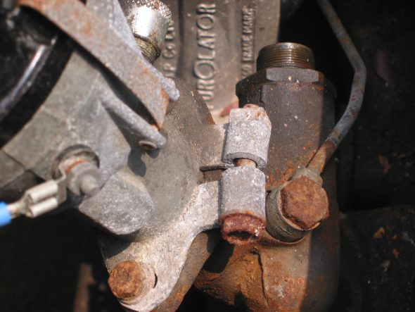
Distributor –  Removed two 7/16” bolts – note position of distributor and vacuum advance. Numbered each wire to the correct cylinder. Disconnect vacuum line and oil feed line to the tachometer drive.

Distributor Wiring

Distributor

Distributor Cap

Distributor Mounting Clamp

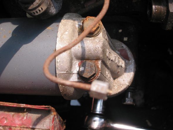
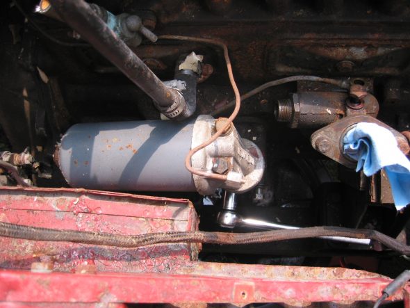
Oil Filter –  Removed two large bolts to the engine block.

Oil Filter Mount

Oil Filter

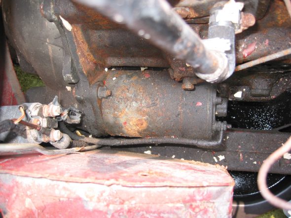
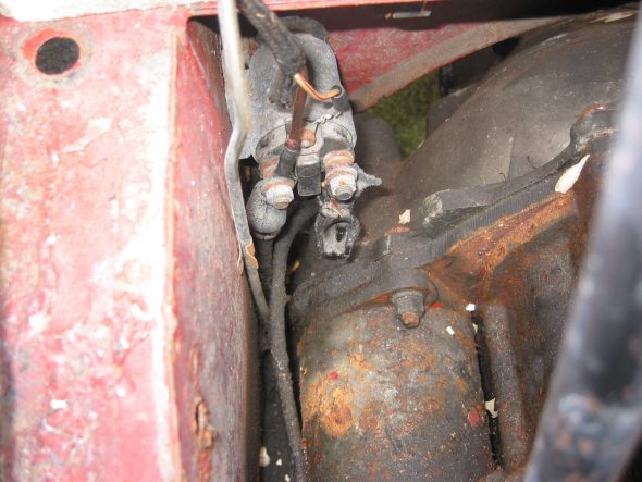
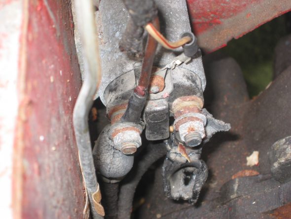
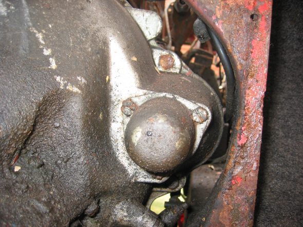
Starter and Solenoid  Disconnected solenoid to starter lead cable. Loosen two 9/16” bolts accessed through the interior bulkhead and under car.

Starter

Starter Solenoid

Starter Solenoid Wiring

Starter Cover

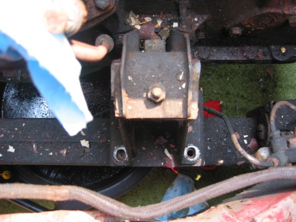
Engine mounts – Removed 4 bolts from right front to frame. Then removed left side.

Engine to frame Mount

Ground strap –  Disconnected the strap from the frame.

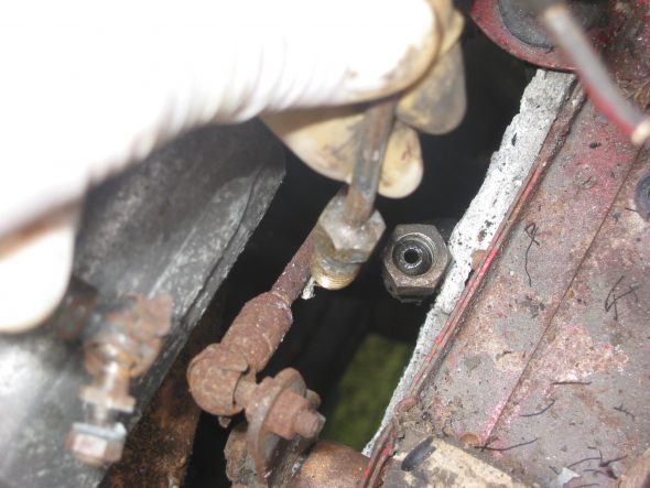
Oil pressure line –  Disconnected the line at top union near intake manifold.

Oil Pressure Line Disconnect

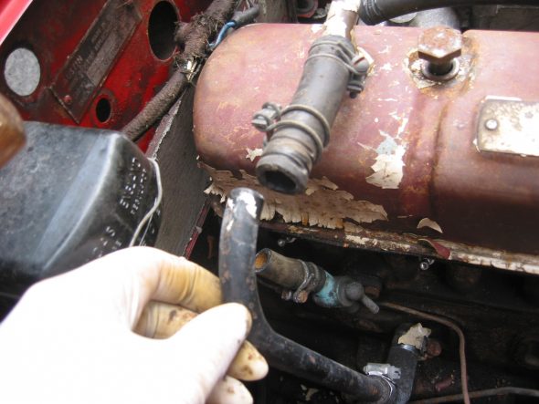
Breather pipe –  Disconnected the pipe at the “T” junction on the rocker cover.

Breather Pipe Disconnect