

Fuel Pump and Fuel Lines
The Original Fuel System
The fuel system consists of the fuel tank, the fuel pump, the carburetters and the air cleaners. The original fuel system included the following: Fuel tank: 14.4 U.S. gallon steel tank Fuel pump: SU electric Carburetters: Twin 1 3/4” semi-downdraft HD6 Air Cleaners: Coopers “pancake” type.
Modified Fuel System
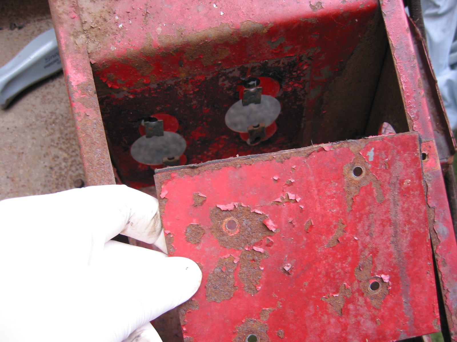
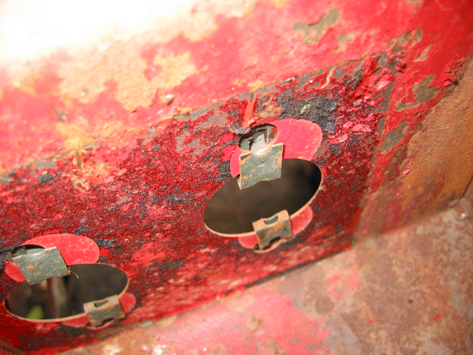
Aluminum Fuel Tank
I replaced the steel tank with an aluminum version sourced from Hemphill’s Healey Haven in Maryland.

Aluminum Fule Tank
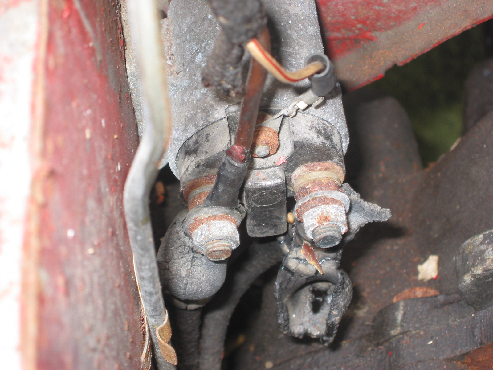
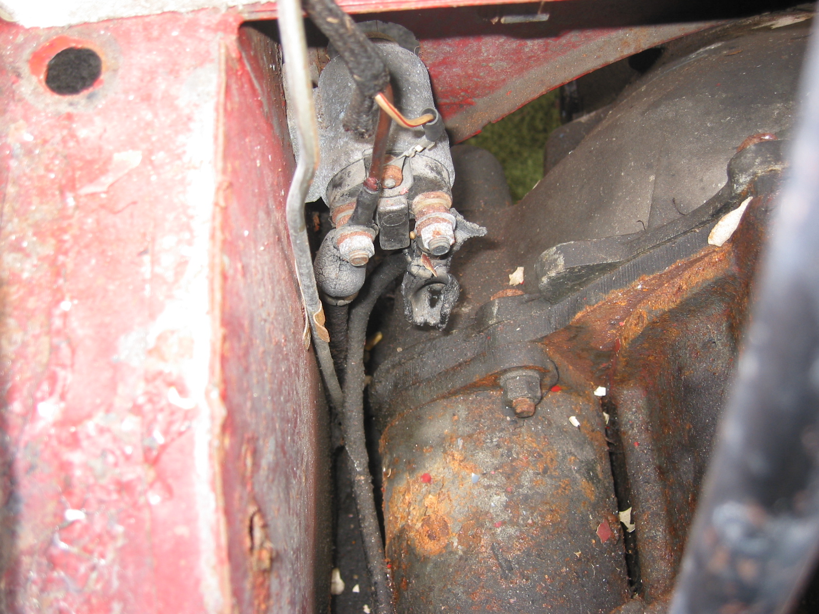
Solid State SU Fuel Pump
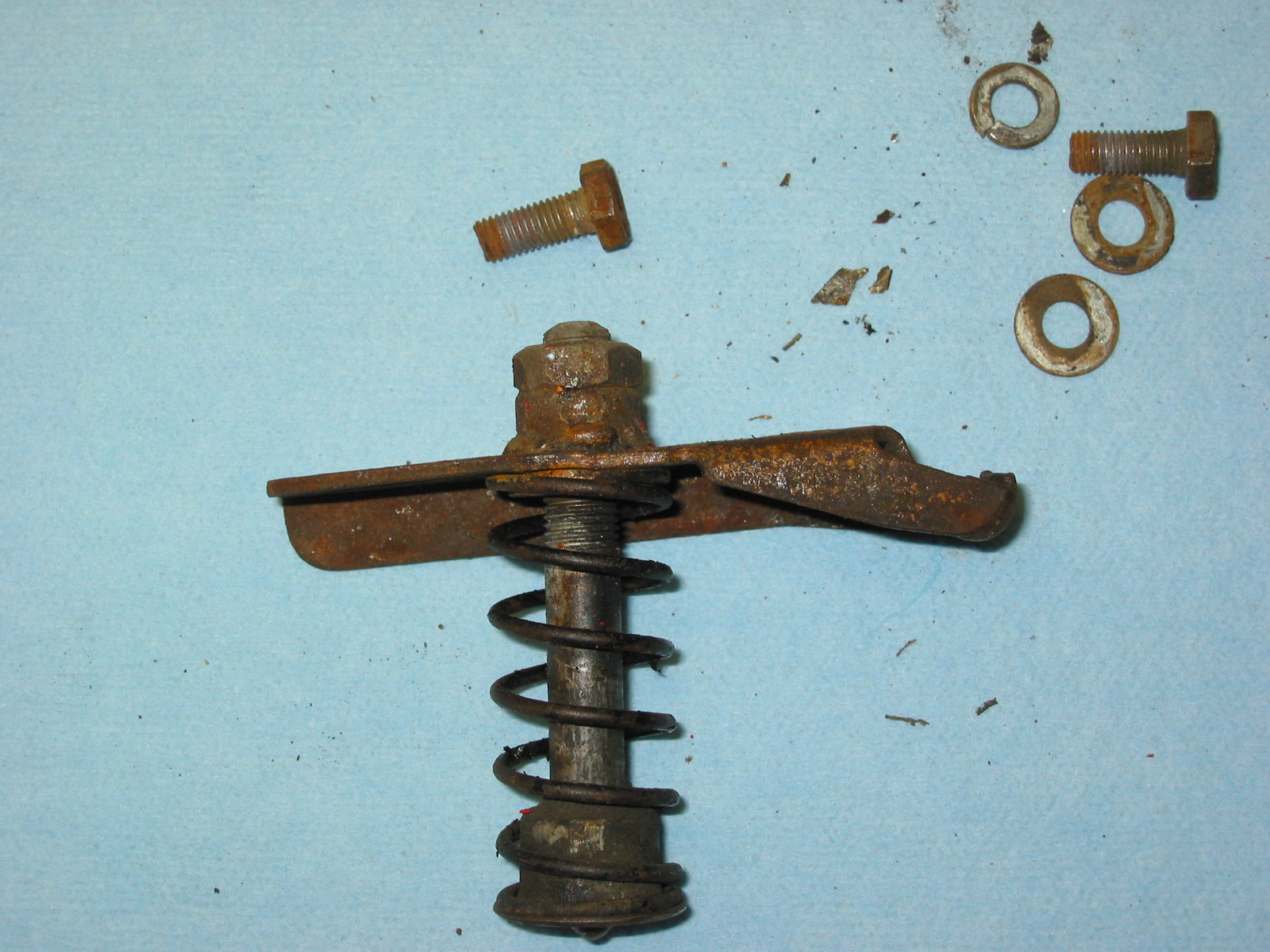
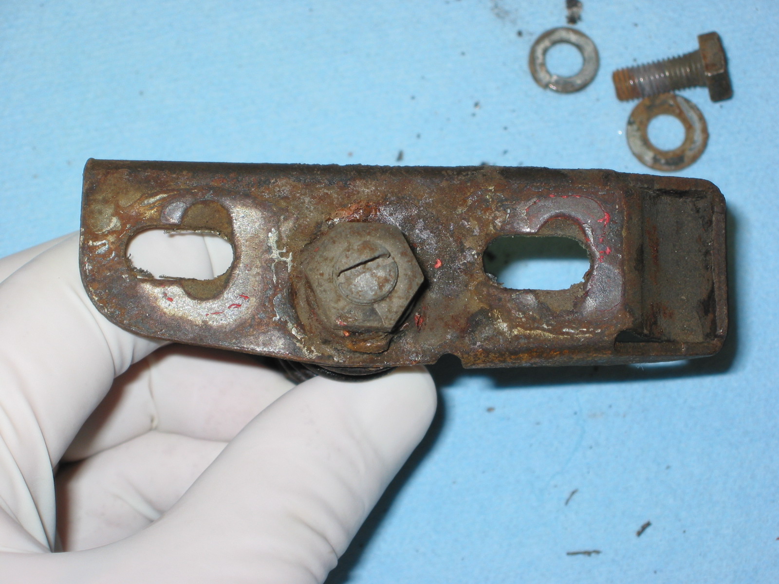
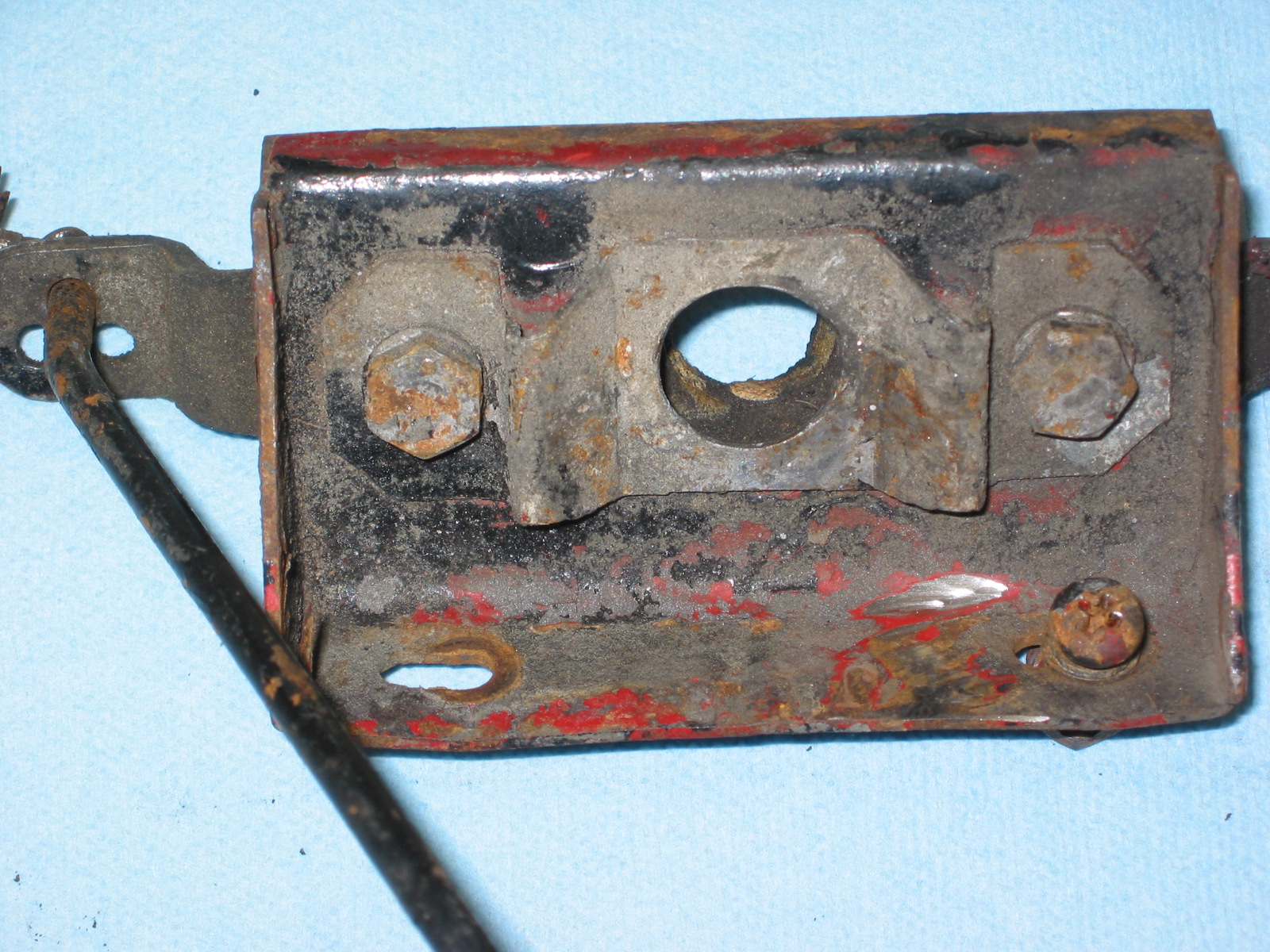
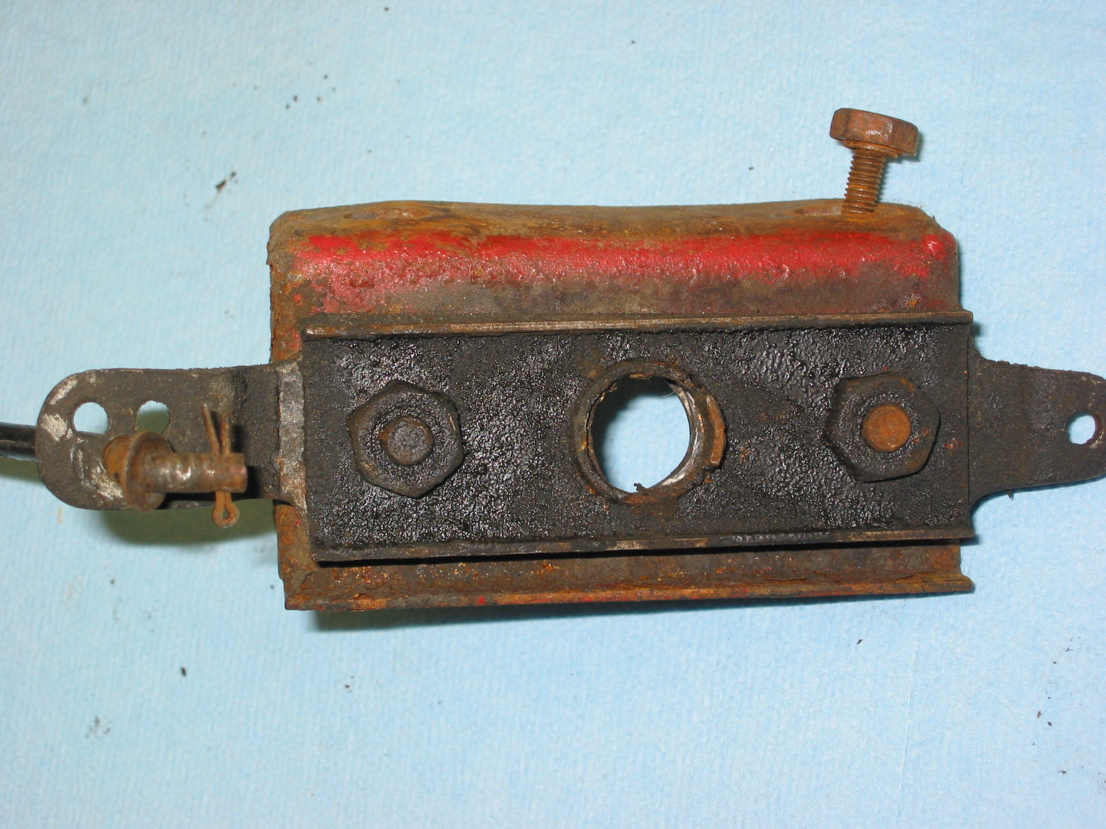
I used the original mounting bracket, but replaced the pump with a solid state version of the original fuel pump. The pump was supplied by Burlen in the U.K.

Solid State Fuel Pump
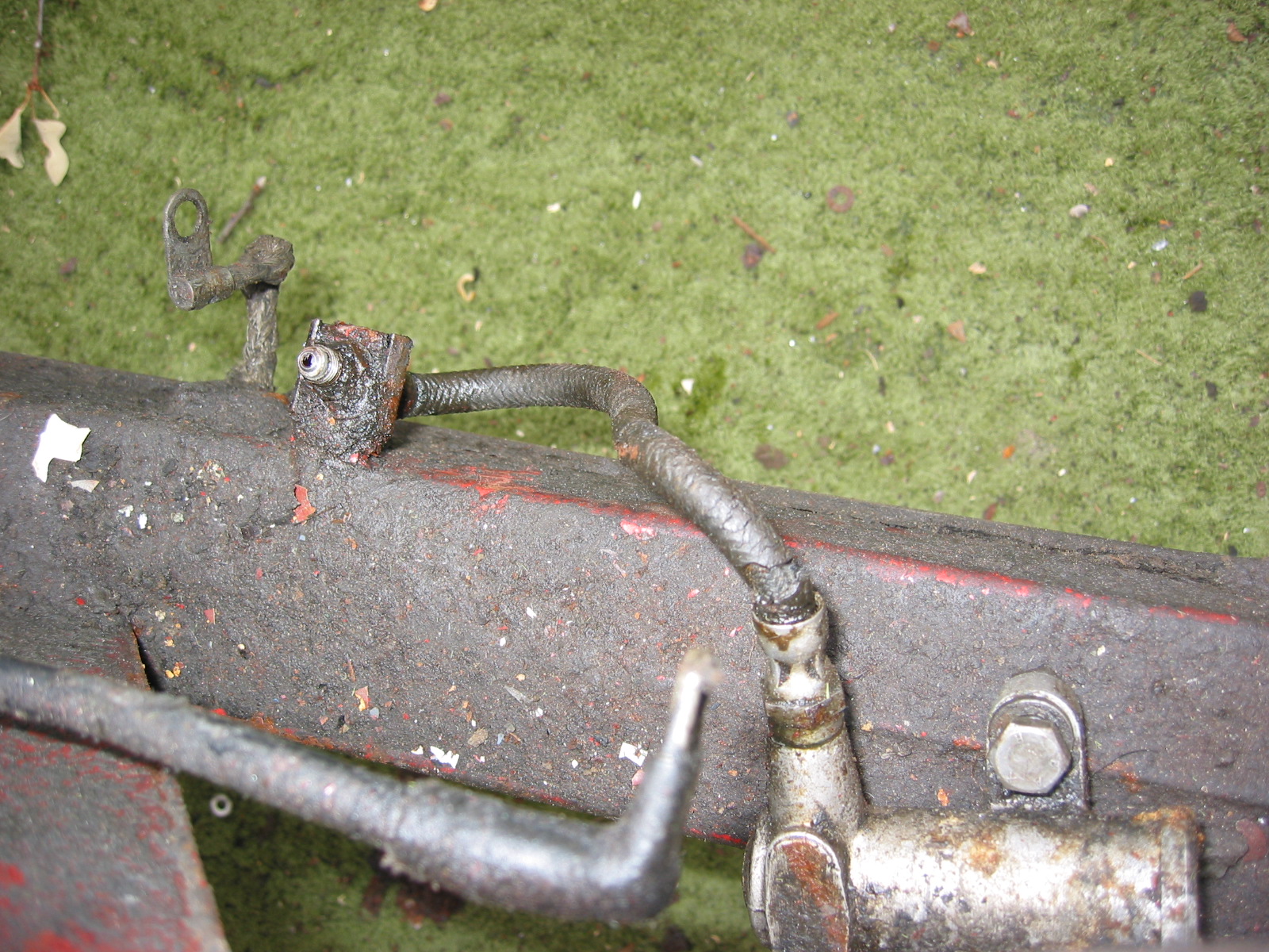
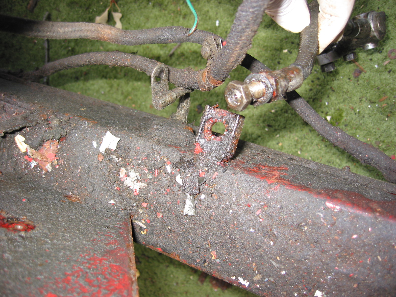
Redundant Fuel Pump
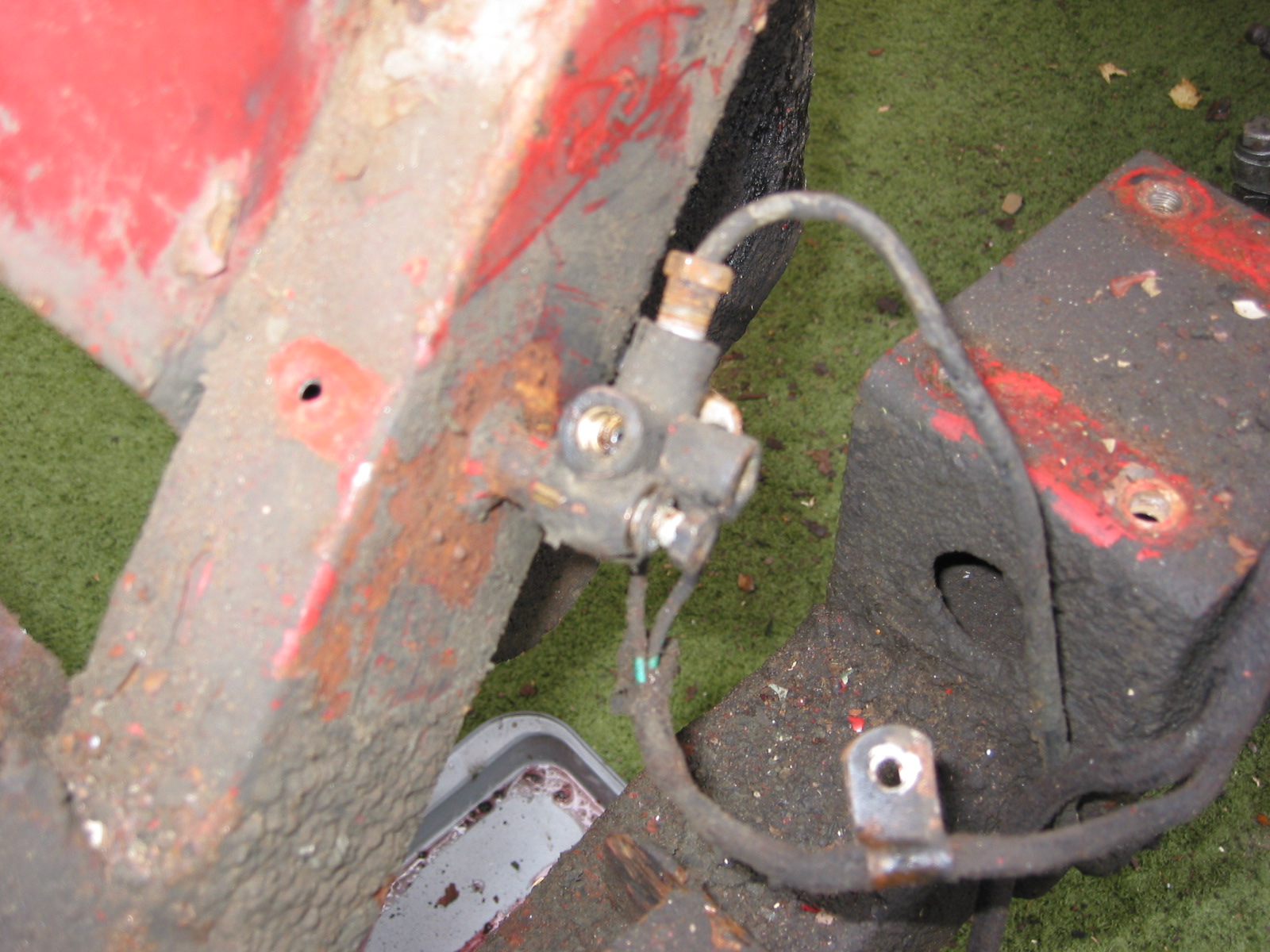
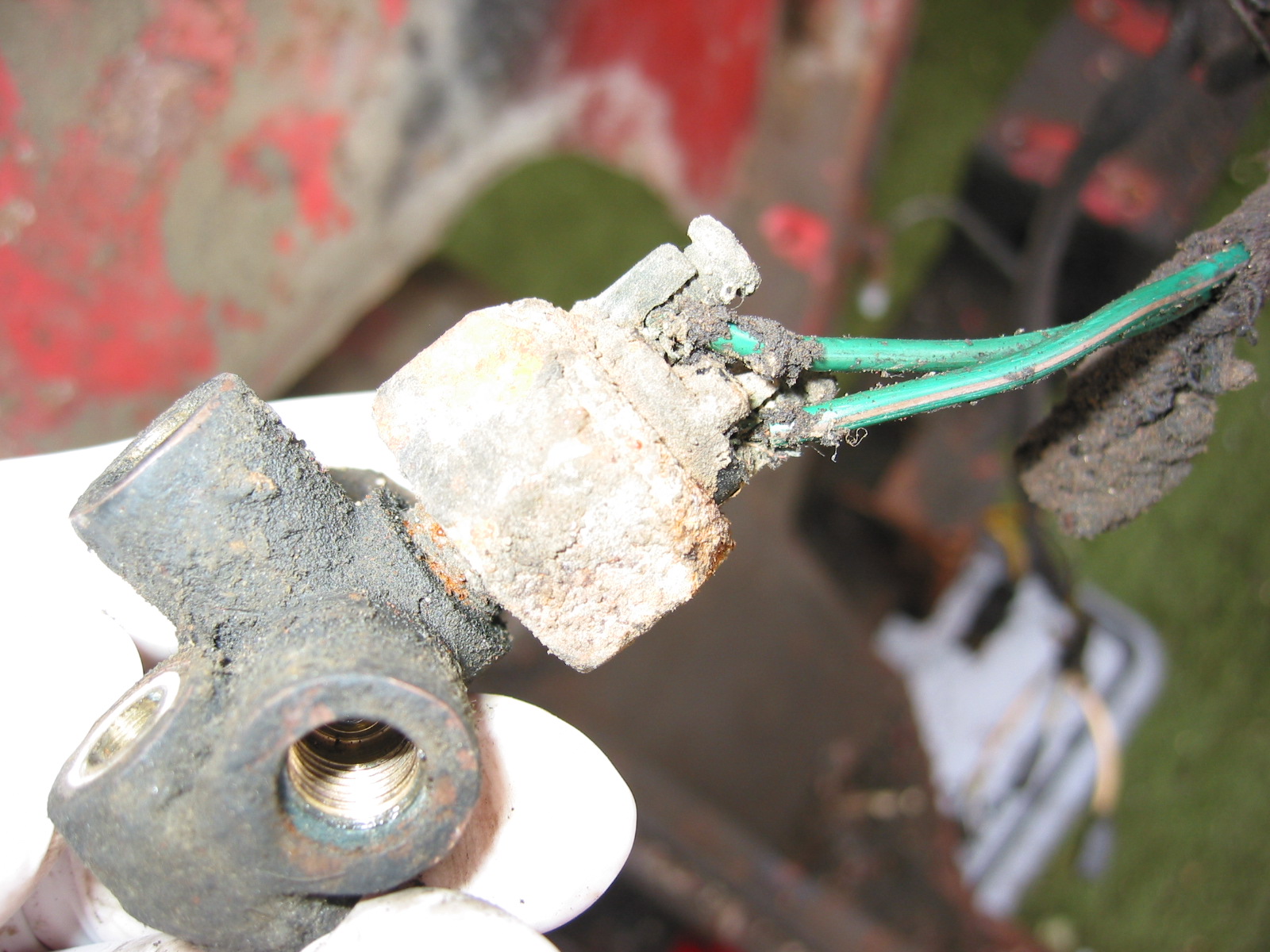
I expected the solid state unit to perform better than the original with its “points,” but I still remember problems with the original pump while I was driving the car in college. I would give it a few good “whacks,” and it would start pumping again. I had read about installing a redundant pump either parallel or in-line to avoid dead fuel pump problems. I mounted the auxiliary pump on the rear boot wall and ran it in-line with the SU. The restoration blog explains the installation. I used a Master E8016S electric pump available from Autozone. I installed a toggle switch on a small switch panel under the wiper motor that controls the fuel pumps. At center, neither pump is activated (a great anti-theft device); a throw upward activates the SU pump, and a throw downward activates the Master Pump. The pumps can be switched on the fly.

Master Fuel Pump

Auxiliary Fuel Pump Installed

Toggle Switch Panel
Fuel Gauge Dampener
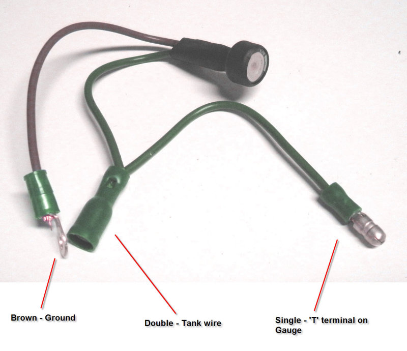
Every Healey owner experiences the erratic swings of the fuel gauge needle. Zims Autotechnik, www.allzim.com , 1804 Reliance Parkway, Bedford, TX 76021, 800-356-2964, sells a little electronic device (see image to the right) that mitigates the needle swing. I believe it was originally conceived for the Porsche 356. Steve Gerow shared this little tip. I ordered one, installed it in a few minutes and sure enough it works! $19.95 for the part. Fuel Gauge Dampener instructions.JPG are provided, but Steve’s photo tells the whole story!
Fuel Gauge Dampener
Carburetters
I replaced the original HD6 SU carbs with 2″ HD8s to boost HP a bit. I purchased these from someone on the Healey list and had them rebuilt by Joe Curto. I was pleased with his results. The older used units polished nicely. Using the HD8s did require switching to a later intake manifold from a BJ8 as well, to take advantage of the 2″ diameter carbs.

HD8 Carbs
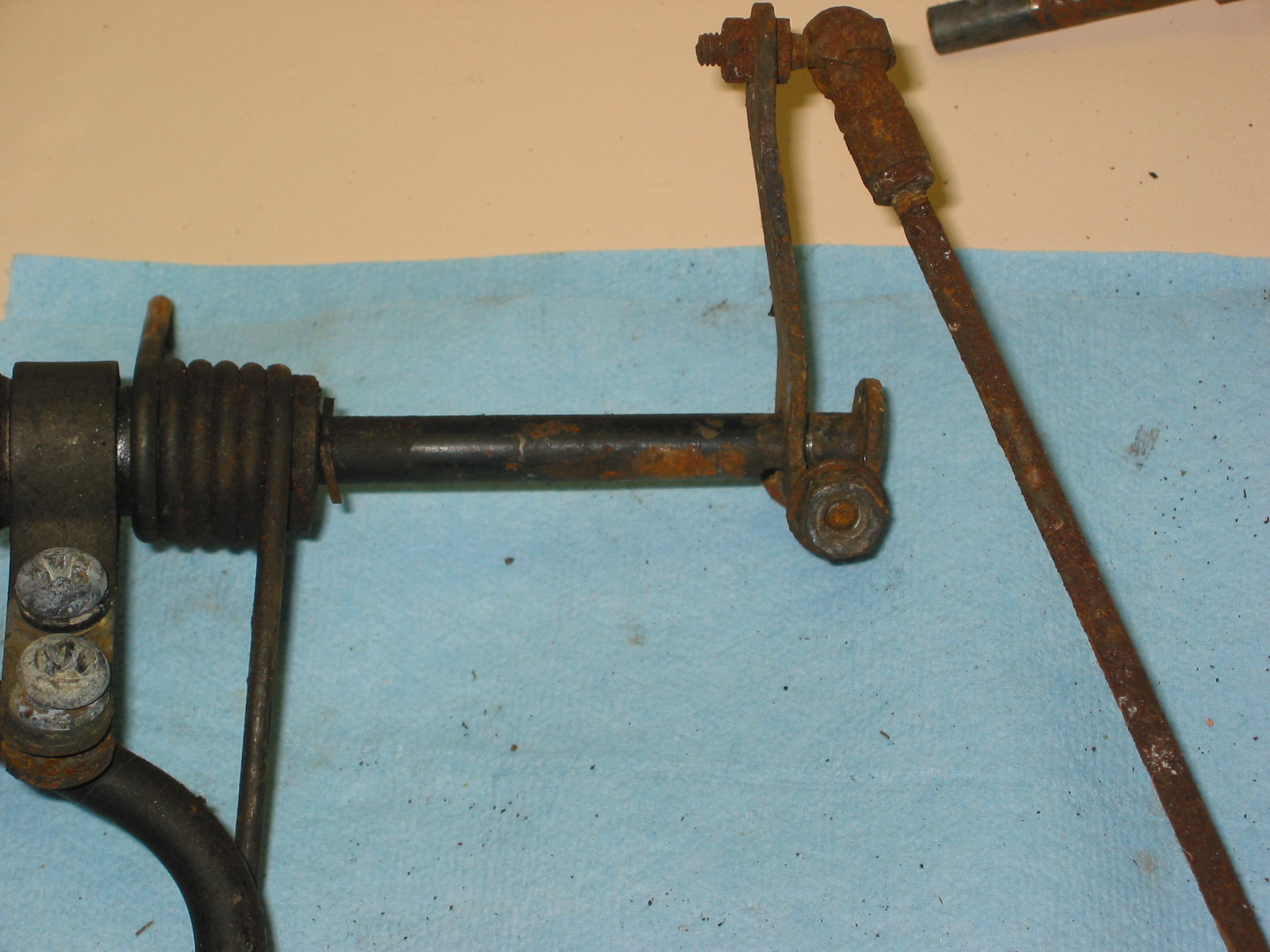
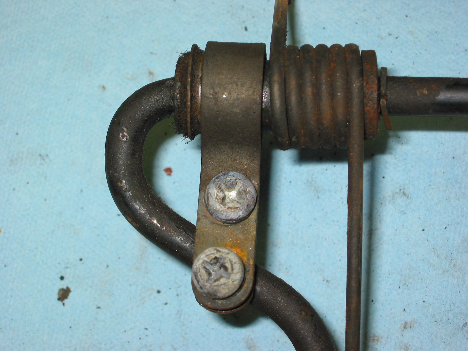
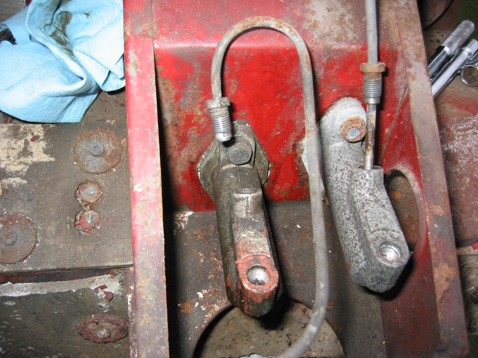
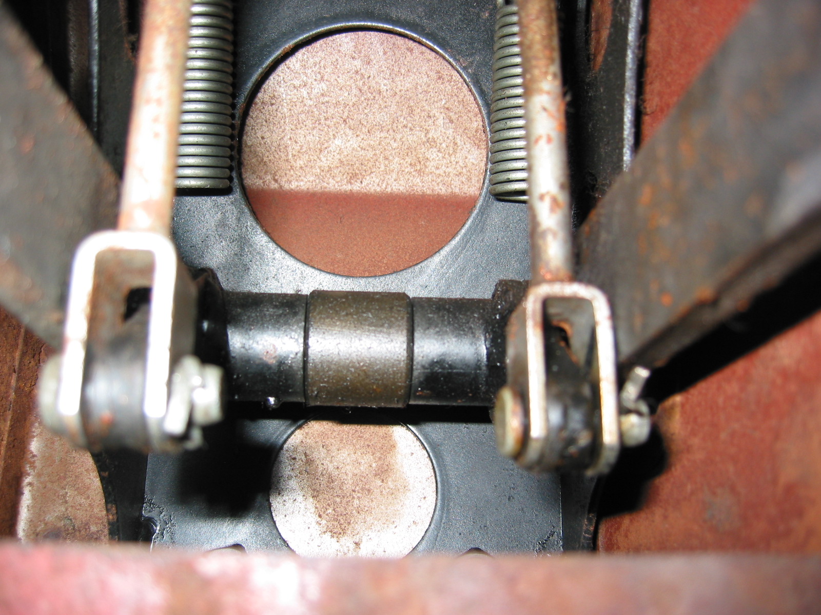
Carburetter Choke
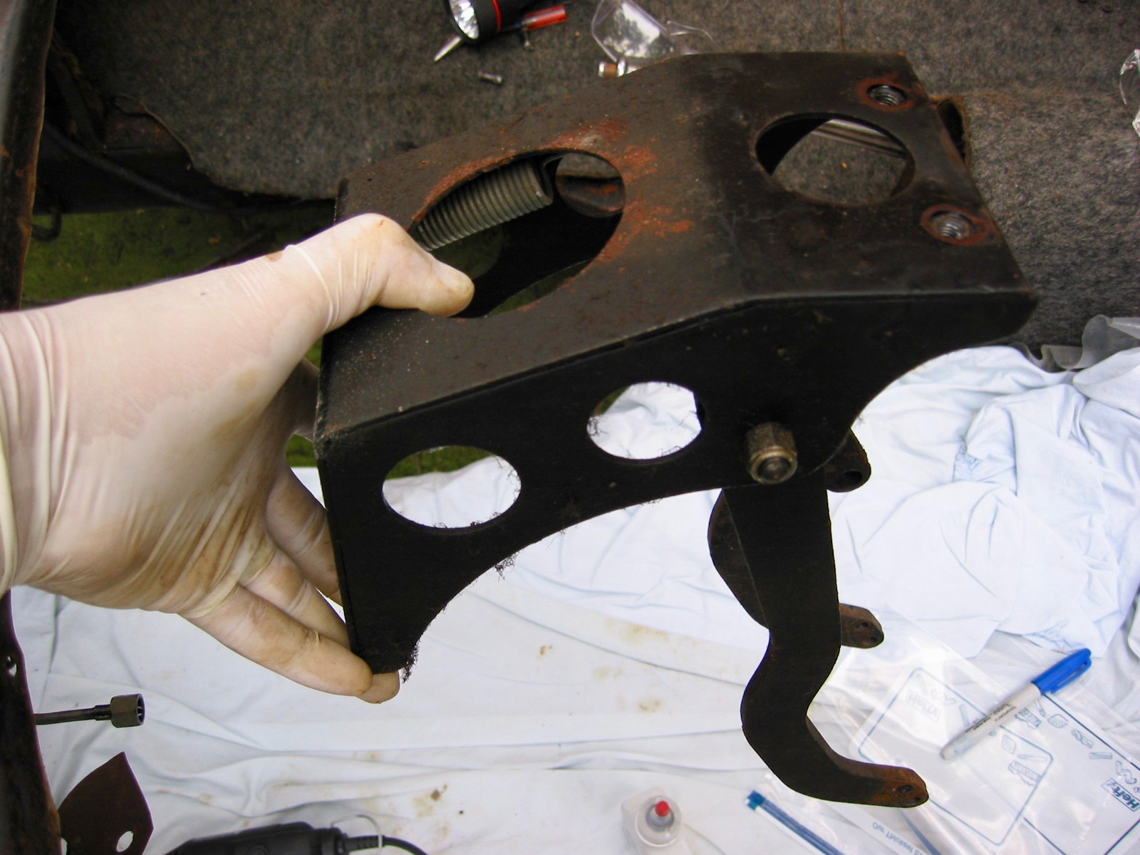
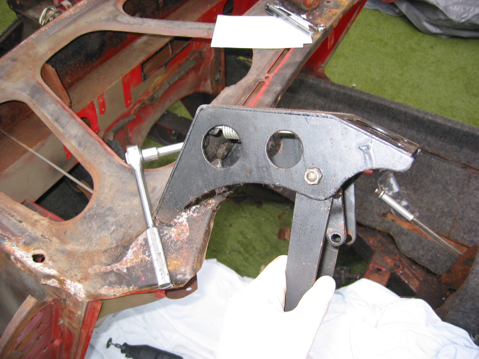
The choke mechanism for the BJ8 carbs is a dual line system as opposed to the single cable used with the original HD6 carbs. So, I ordered the HD8 choke bracket and cabling and installed it in the Bloody Beast.

Choke Firewall Bracket
Air Cleaners
In 2008 when I restored my car, I decided to replace the original pancake Cooper air cleaners and use the “itg” competition foam air cleaner available from Denis Welch. The air cleaner is a single unit working with both carburetors. For appearances, I painted the red plastic body of the air cleaner a gloss black.
However, recently, as part of my “ten-year renewal” process I have moved away from the ITG filter and now use twin ram pipes with individual trumpet filters. This change is explained in this post: https://valvechatter.com/?p=12574

ITG Air Cleaner
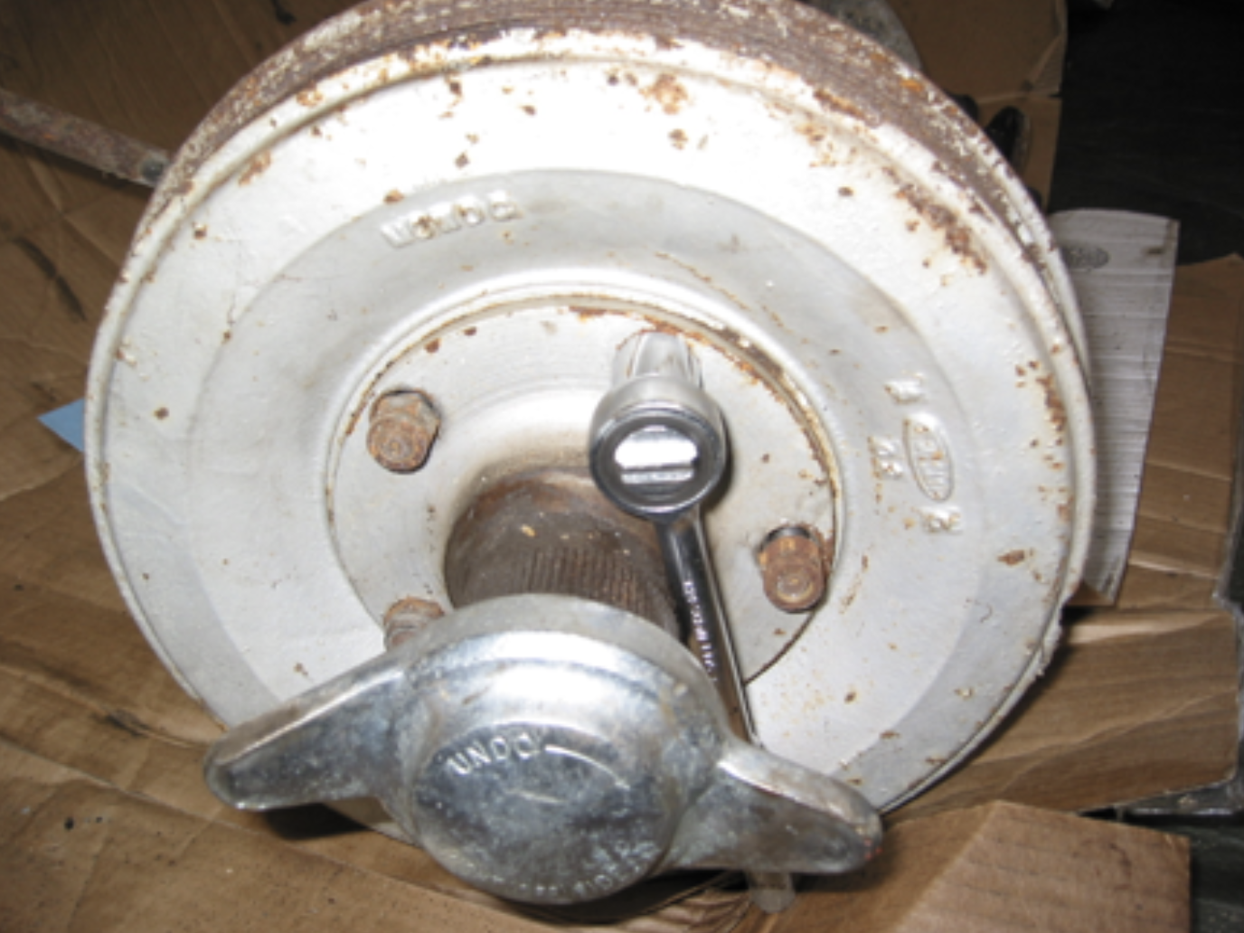
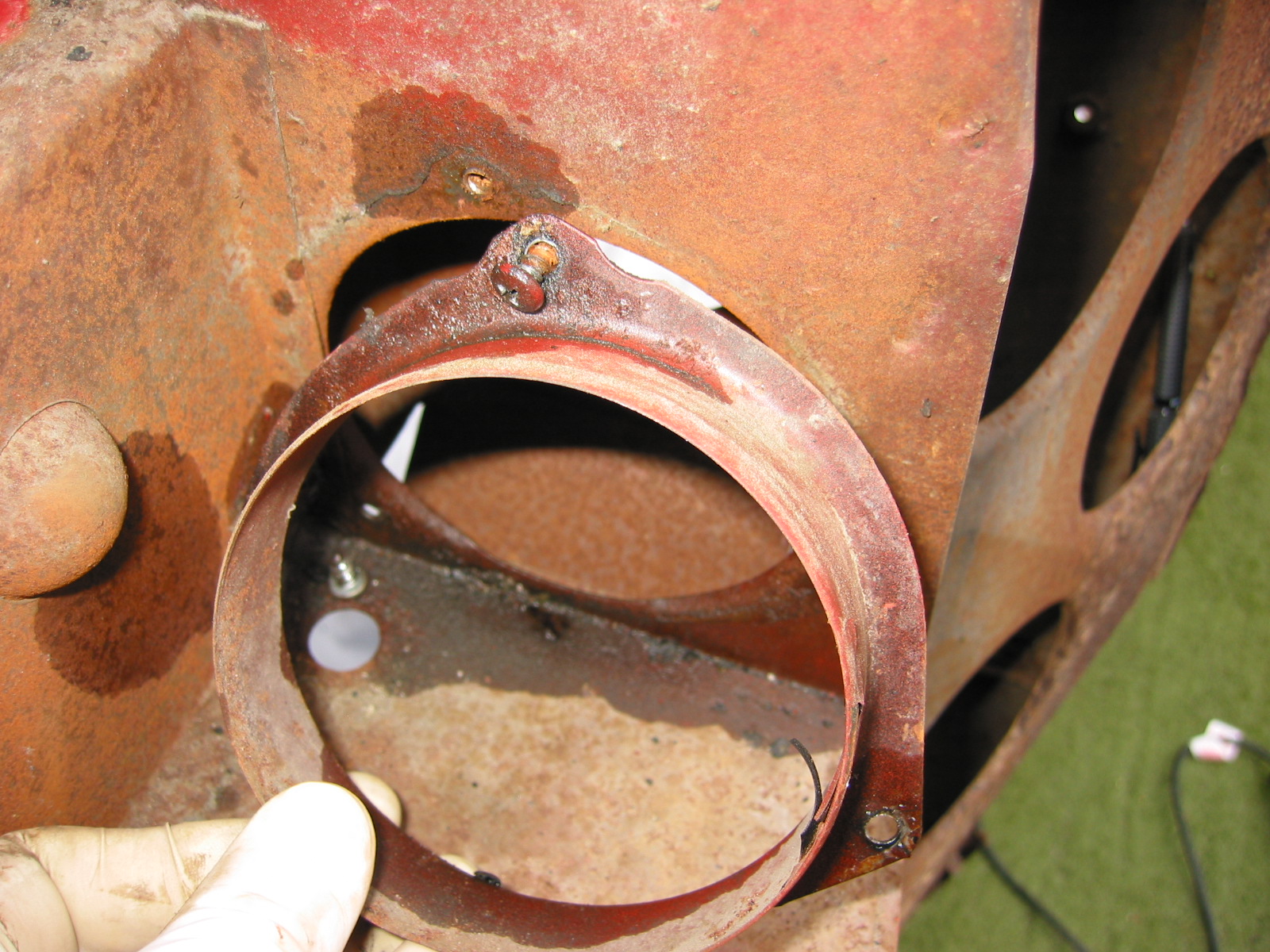
Aston Quick Release Fuel Filler Cap
I like the looks of the racing heritage Aston cap that also has its practical ease of use advantage. To install, it is necessary to cut off the original fuel filler pipe and solder a threaded ring onto the pipe. The cap then screws onto the collar. It gives a very nice finish to the fuel system!

Aston threaded collar

Aston Fuel Filler Cap


