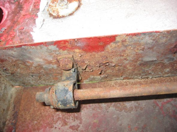
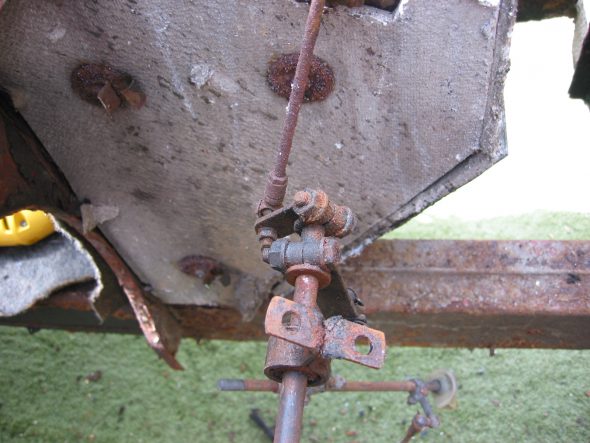
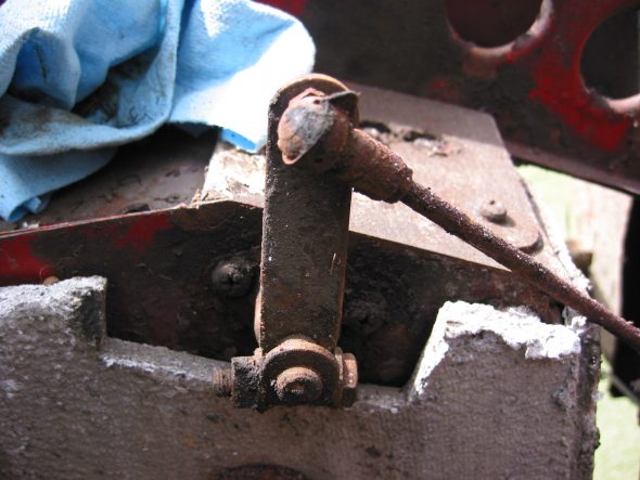
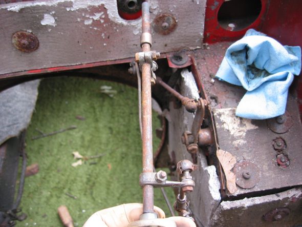
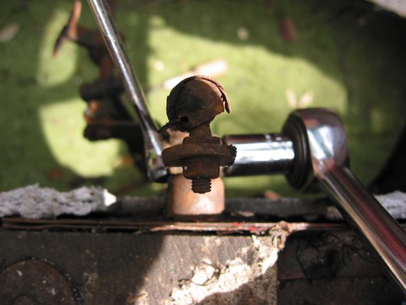
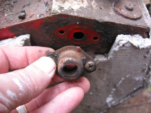
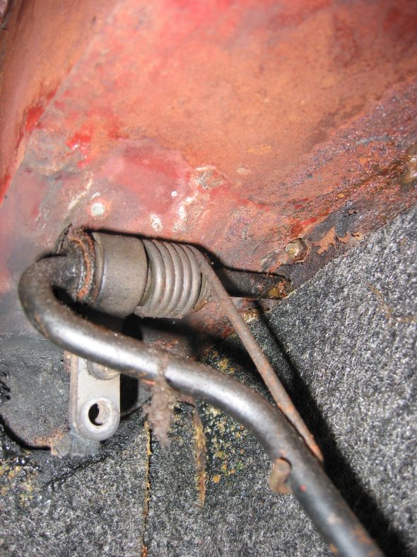
Fuel Pumps, Fuel and Brake Pipes and License Plate

The Bugeye began life with a 948 cc four cylinder motor that had a mechanical fuel pump mounted to the engine block. We converted to an electronic SU negative ground 12 volt fuel pump years ago and it was mounted in the engine bay. Then we mounted the pump in the rear of the car as outlined in an earlier post: https://valvechatter.com/?p=13599

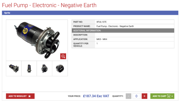
SU electronic fuel pump negative earth

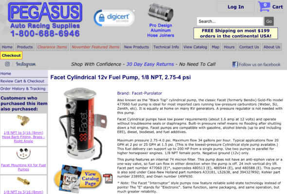
The SU pump was sourced from AH Spares in the UK. After acquiring the Michigan body shell we decided to modify the fuel delivery system yet again to incorporate a redundant electronic pump to have a ready back up in the case of a pump failure. The back up pump was sourced from Pegasus Racing and it is a Facet Cylindrical pump rated at 2.75-4 psi.

Facet Cylindrical 2.75-4 PSI Negative earth electronic fuel pump

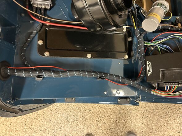
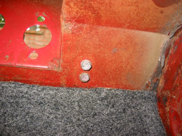
The two pumps are installed in series and will be wired with a toggle switch permitting the selection of either pump or no pump at all – an effective theft deterrent. Nut serts (1/4″-20) were installed in the rear bulkhead to serve as mounting points for the rubber isolators, also purchased from Pegasus, that fit between the bulkhead and the pumps. 

A new stainless steel pre-bent fuel pipe was purchased from Summit Racing, modified to accommodate the new pump setup and installed in the car.

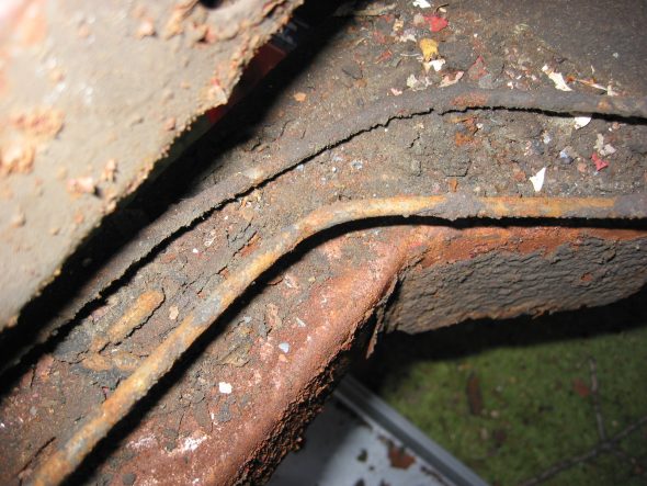
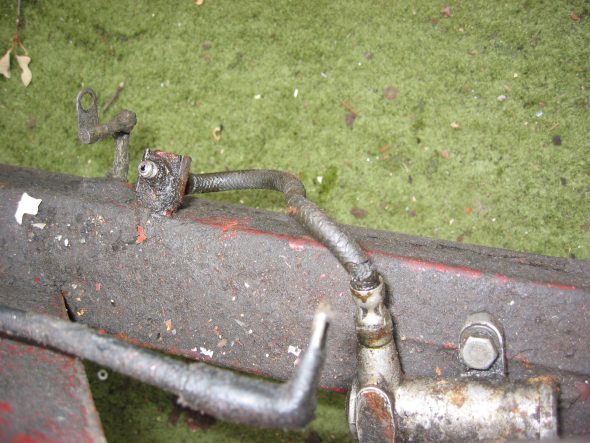
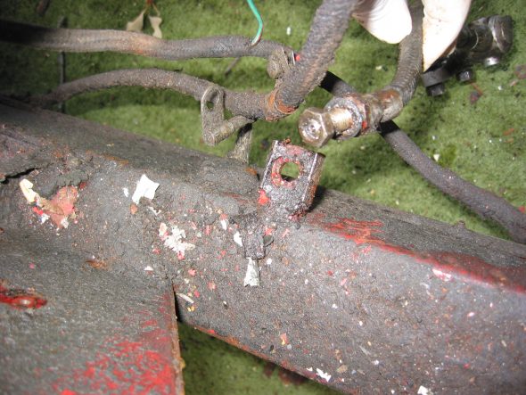
The Cunifer (nickel/copper alloy) brake pipes were completed and trial fitted to the car. In a few places this required cutting pipe and making bubble flares on the end of the pipe. Bubble flares are similar to but not the same a double flares.

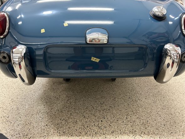
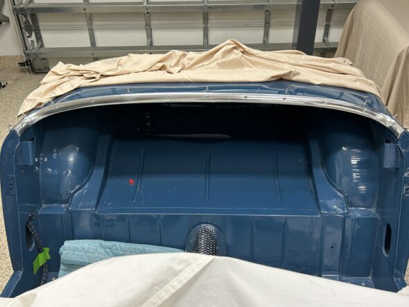
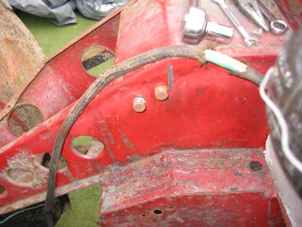
Lastly, nut serts were installed in the existing holes in the back of the body for the license plate and the plate was also fir to the car.

All of these actions are shown in detail in Bugeye Restoration Video Fifty-one: https://vimeo.com/884536057/11e607b366?ts=0&share=copy


xx

Bugeye Rear Axle Assembly

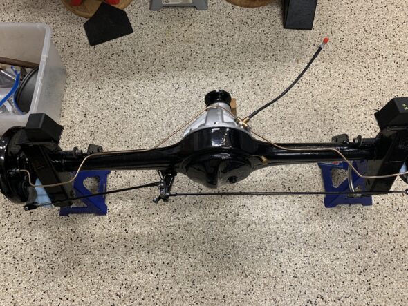
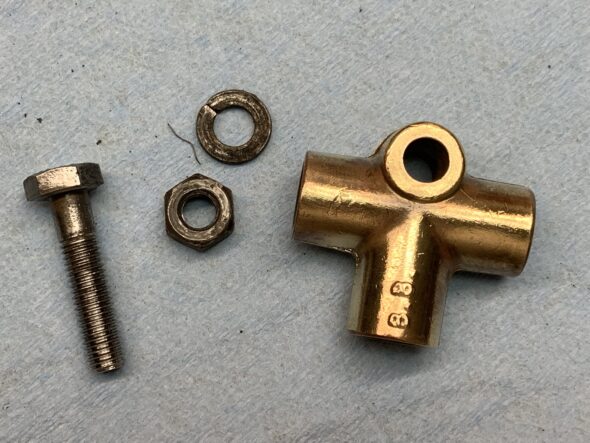
Since the last entry, the axle was painted with POR-15. The preassembled MG Midget brake assemblies were mounted to the axle and rotated to be in the proper position to align with the handbrake rods. Initially they were installed in the wrong orientation. The 3.9 differential was installed in the axle as well as the new cunifer brake pipes. The brake pipe union was cleaned and polished. A new Goodridge black stainless brake hose was connected to the union using a new copper crush washer.

A new brass Land Rover axle breather was purchased and installed on the axle. The MiniMania adjustable handbrake rods were painted and connected to the brake levers and the compensator lever with new clevis pins and felt anti-rattle washers. Finally, the rubber rebound buffers were attached to the axle with the ends of the split pins facing to the front of the car and rubber caps were placed on the bleeders. All of this work is shown in video Episode Nine.

https://vimeo.com/769593182/8c2f05ffc9

Installing the hubs turned out to be a much more challenging job than expected. Based on what others had shared we were under the impression that swapping the original brake assemblies for the later Midget brake assemblies was a plug-and-play process. At least in our case, it was not! As can be seen in the next video, the flange on the Midget back plate stood higher than that on the Bugeye original backplate. This meant that as the Hub was pressed down until it was seated, it was fouling against the backplate flange making it almost impossible to turn. Video Episode Ten shows the problem we faced.
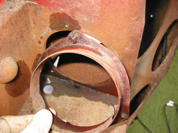
https://vimeo.com/758343871

When the Sprite Forum members were queried about this problem, others did mention the possibility of this problem. It was suggested that the flange should simply be trimmed about an 1/8″ so that the hub would not contact it when pressed down fully. So, we got out the Dremel and did just that. Fortunately, that solved that problem.

New hub bearings were installed. This video, Episode Eleven, shows the full process. Timken 207FF bearings were used.

https://vimeo.com/769633649/bd8bbee949

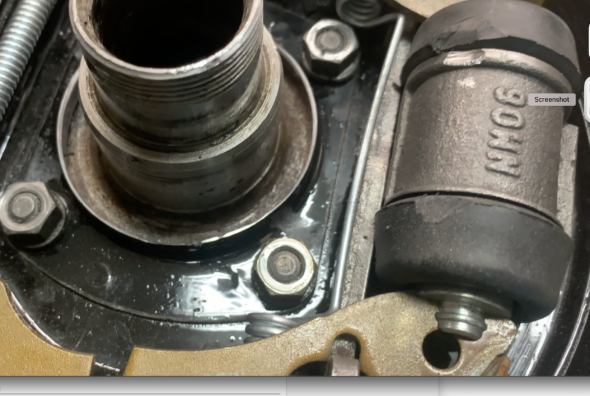
Following installation of the hubs, I noticed that one of them was still encountering some resistance in rotating. Turned out the the raised portion of the hub where the studs are located was ever so slightly touching one edge of the brake cylinder. While I was not happy with my solution, it did solve the problem. This can be seen in video Episode Twelve.

https://vimeo.com/769896299/f92cfe0068

Brake Cylinder Relieved

True to form, when we installed the brake drums on to the hubs we once again encountered resistance to turning! This easy swap to later rear brakes has not been without its challenges. Sure enough, after checking with others on the Sprite Forum it turned out that people did often have to grind down the outside edge of the drums to get them to fit without fouling against the backplate. Whether this is an issue with drum manufacturing tolerances or some other issue – we just don’t know. So, out came the angle grinder with a cut off wheel and we cut some of the drum away and smoothed the edges as best we could. Once again, we aren’t happy with the approach, but also once again, it solved the problem. Everything now rotates freely. The video Episode Twelve shows the process.

https://vimeo.com/769904083/75a1d4a732

After addressing the relocation of the fuel pump from the engine bay to the bulkhead behind the passenger compartment, the installation of a new fuel tank and new fuel pipe, the installation of new rear leaf springs and the cleaning and painting of other rear suspension components, we will return to the installation of the completed axle in the car.

Chapter 55 Restoration Assembly, Week Twenty-Five 6/4/2007

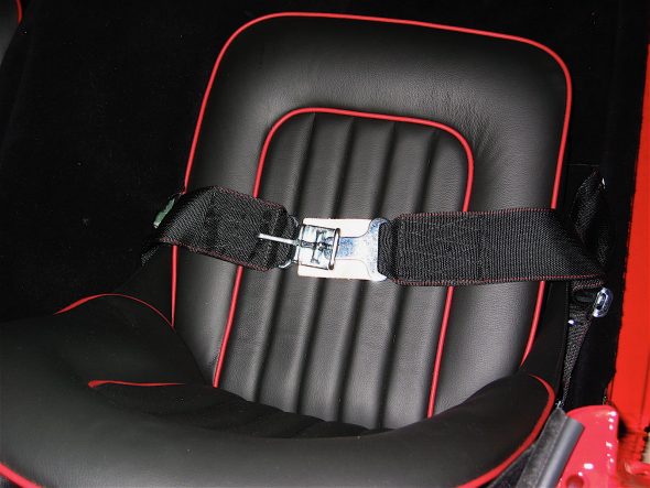
Installing the seat belts was fairly straight forward. I had drilled holes earlier for the mounting kits. I was going to go with the seatbelt/shoulder harness assembly sold by British Car Specialists, but ultimately decided to go with the “vintage look” racing belts sold by Moss Motors. These belts work beautifully with my interior color combination! The shoulder harness kit would have been the best call for safety, but the belt retracting mechanism to be mounted on the rear quarter panels just looked too contemporary. I am pleased with the result!

Seat belts

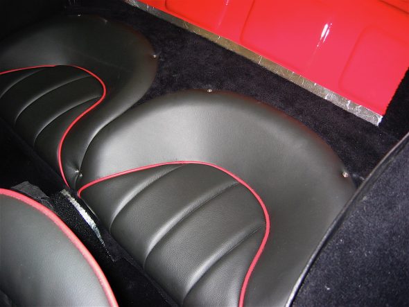
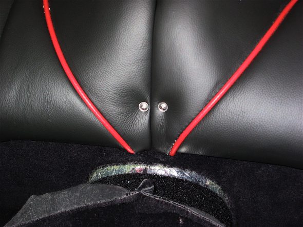
I had been dreading a job, that as things turned out, was not as challenging as expected. I needed to locate and install the #6 stainless screws with trim rings that secure the rear jump seats. I was scared to death that in doing so I would damage the beautiful leather trimming job done by Heritage Upholstery and Trim.

To prepare for installation, I first glued marine class rubber weather stripping around the rear seat tubs. I peeled back the leather on the underside of the seats, located the original screw holes, and carefully punched holes through the leather. A previous owner had used oversize screws to mount the seats and the holes in the superstructure were bigger than they should be for #6 screws so I had the holes filled by Jeremy Turner at Maple Hill Restorations while bodywork was being completed. Therefore, this job required locating new holes in the superstructure and drilling them.

I had Judith, my wife and able assistant, sit in each seat to press it down to the mounting platform and position them as well as possible. I then marked each hole location. I used a 1/8” hollow punch to remove carpet, dynamat and aluminum insulation from each hole location and drilled the holes in the superstructure. Everything turned out great and the installation appears as original. I really don’t care for the look of the stainless screws in the leather, preferring the BJ8 seats that have studs to secure the seats, rather than the screws, but I decided to remain original on this matter.

Rear seat fasteners

Rear seat fasteners

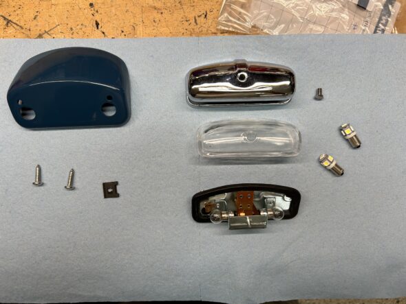
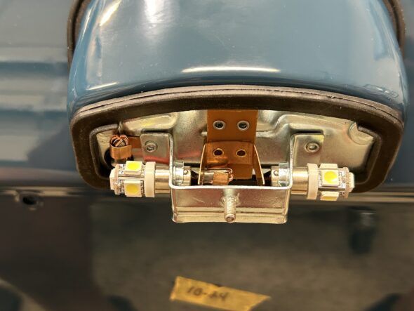
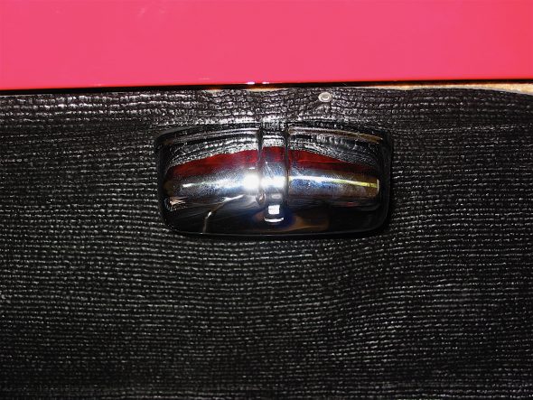
I had never finished the installation of the courtesy lighting in the boot, so it was time to return to that task. I used a rear license plate lamp to supply light and modified the chrome casing to permit more light to enter the compartment. The lamp was wired to the courtesy lights in the interior, so with a flip of the toggle switch or with a click of the remote control “clicker,” the boot lamp is activated.

Boot light

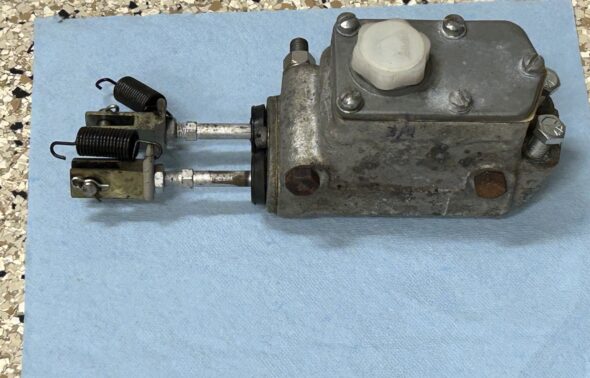
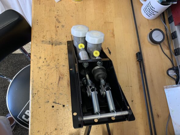
I can’t say why I have not installed the brake and clutch master cylinders and pipes before now? I secured two new master cylinders into the pedal box with the four 5/16” hex head bolts. Aluminum packing shims were used on both master cylinders.

Master Cylinders & Lines

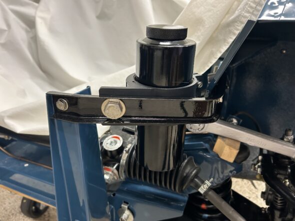
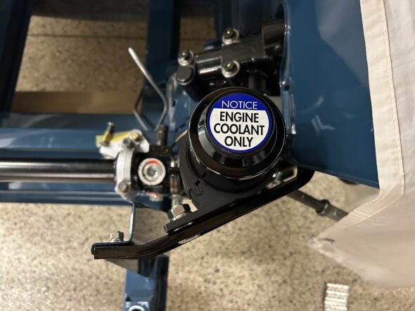
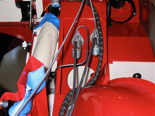
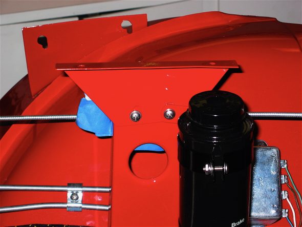
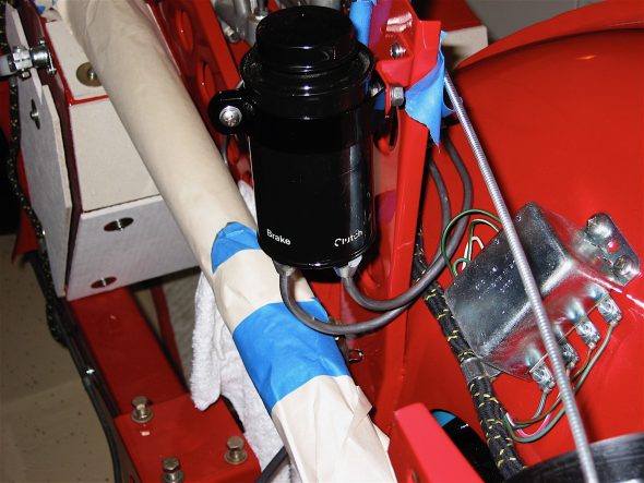
The LH and RH bonnet opening support plates were attached to the frame upright and the brake reservoir was clamped into its bracket on the LH post. The two hydraulic pipes were fitted and the double clamp securing the pipes to the inner fender was screwed in place.

RH Bonnet Opening Support Plate

LH Bonnet Opening Support Plate

Brake Reservoir and lines

Chapter 10 – Disassembly

August 17, 2002

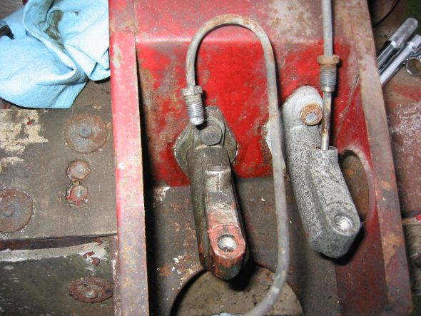
Brake and Clutch Master Cylinders –  Loosened lines from cylinders. The brake line from the master cylinder to the 4 way junction has 3 clips and fasteners to the union facing the master cylinder (left side of the car). The clutch line also has three clips: 1 by the solenoid, and 2 on the firewall (high). 

Loosen the 1/2” bolts securing the clutch master cylinder. Pull the cotter pin on the master cylinder shaft to the pedal. Remove the master cylinder. Same procedure for the brake master cylinder. There are aluminum spacers on the top of each master cylinder between the cylinder and the body.

Master Cylinders

Brake Pipe Junction 1

Pedal Box Connections

Pedal Box Bolts

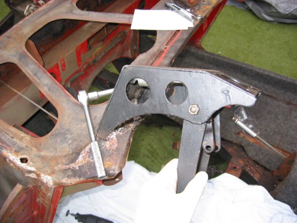
Pedal Box (Pedal Lever Bracket) 

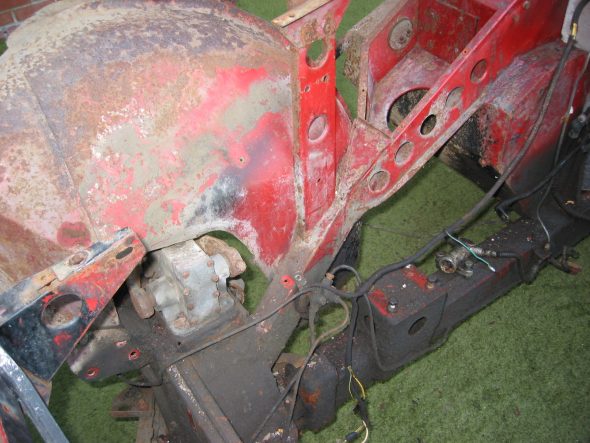
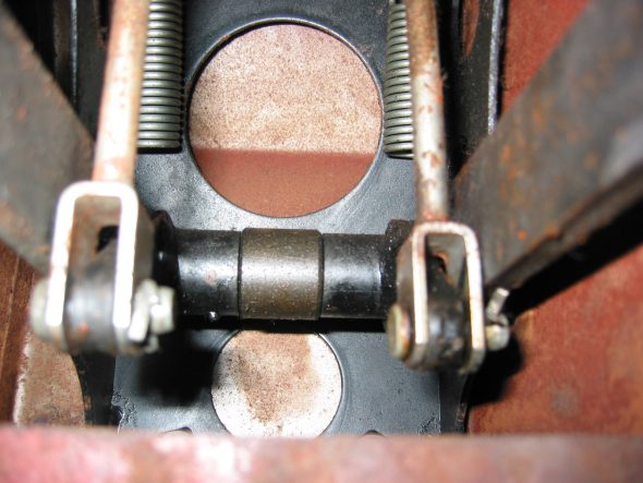
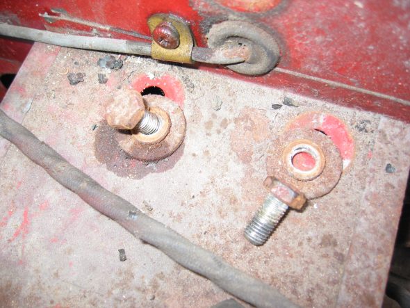
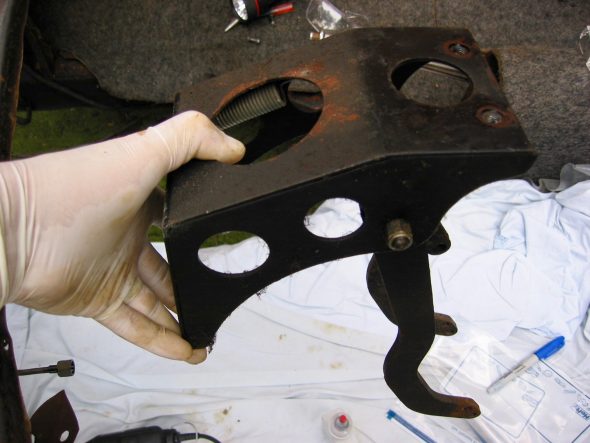
Loosen two 1/2” bolts to remove pedal box mechanism. The box is painted black. Unit will then drop out.

Pedal Box 1

Pedal Box 2

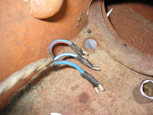
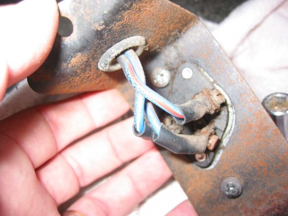
Headlamp Dip Switch Wiring – Pulled the wiring through the pedal box with rubber grommet.

Dipper switch wiring

Dip Switch Wiring

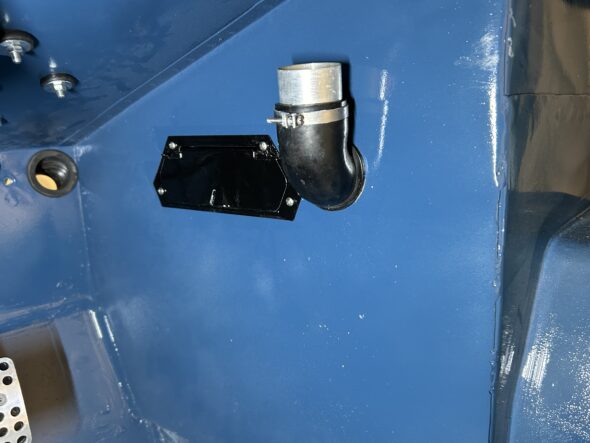
Bulkhead Fresh Air Flange – Removed three phillips head screws securing the fresh air hose flange. Removed flange.

Air Tube Mounting

Brake Lines

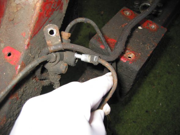
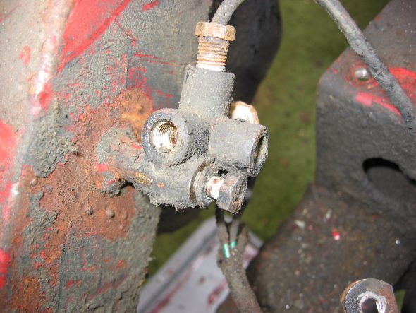
The Brake Lines – fittings were loosened at the 4 way brake union to left front wheel – 2 clips at front cross bar to the front bottom union facing front of car at the junction.  Removed right front brake line from junction to right wheel – top union on junction facing front of the car.

LF Brake Lines

Front Center Brake Lines

Brake Junction

Brake Junction connections

Brake Junction Fitting

Brake Junction 3

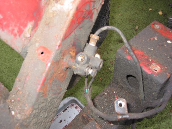
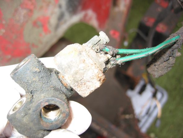
Brake 4 Way Union & Pressure Switch – Removed the Union by loosening one 7/16” bolt to frame. Two wires must be disconnected. Green goes to terminal closest to the engine. The green with pink stripe wire goes to the terminal closest to the frame. One clip holds wiring harness extension to the brake junction located just above the junction mounting post.

Brake Pressure Switch Wiring

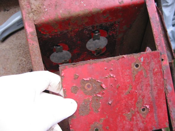
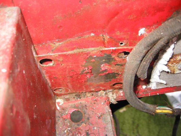
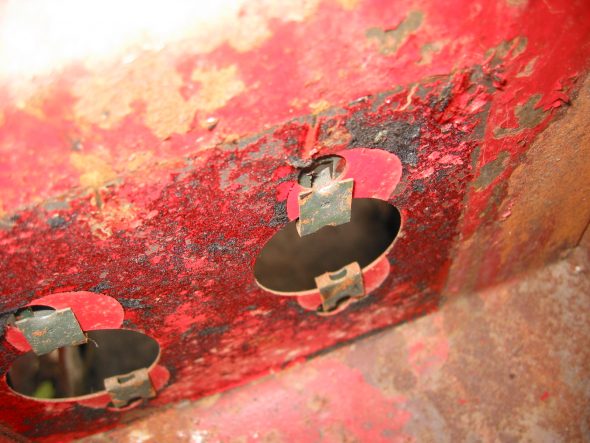
Master Cylinder Sealing Plate (blanking) –  Removed the Plate on the right side of the car. Four Phillips head sheet metal screws. The plate had tar paper on back to seal it. Four clip nuts are used to hold the screws.

Right Sealing Plate

Right Sealing Plate 3

Right Sealing Plate 2

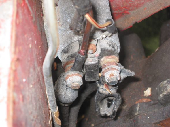
Starter Solenoid. 

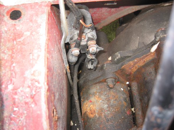
Disconnected the wiring for the starter solenoid. The terminal closest to the engine is for the high tension line from the battery. The terminal closest to the body is or the cable to the starter and the brown ignition wire. The white wire with the red stripe goes to the terminal on top.

Starter Solenoid Wiring

Starter Solenoid 2

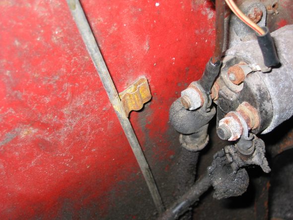
Starter Solenoid connections 2 & Clutch Pipe Clip

Blanking Bolts – Removed 2 blanking bolts in upper right footwell. Remove two blanking bolts in engine compartment to frame.

Right blanking bolts

Right footwell Blanking Bolts

Steering Wheel Blanking Plate – Removed the blanking plate on right side of car. Located behind the asbestos insulation. Four sheet metal screws.

Slave Cylinder

Loosened one nut where hydraulic hose joins frame.

Slave Cylinder connection to Frame Clip

Slave Cylinder Mounting with Clip and shake proof washer

Fuel Line – Loosened the fuel line from the carb feed line and the fuel pump. Three to four clips run along the frame rail from carbs to fuel pump.

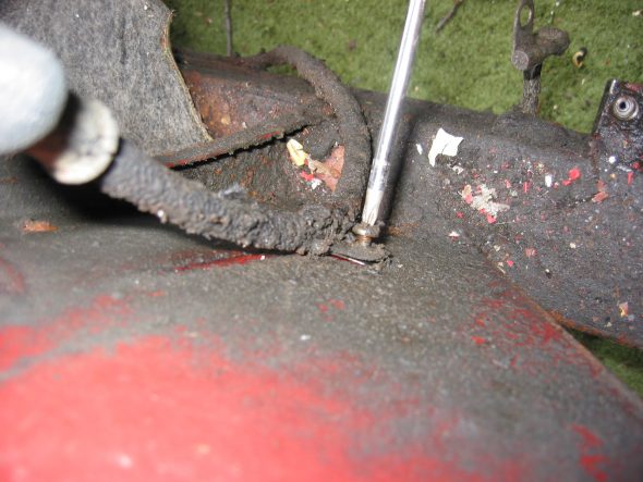
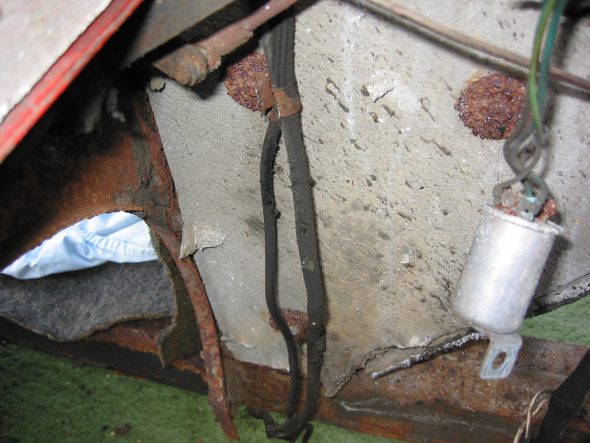
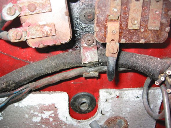
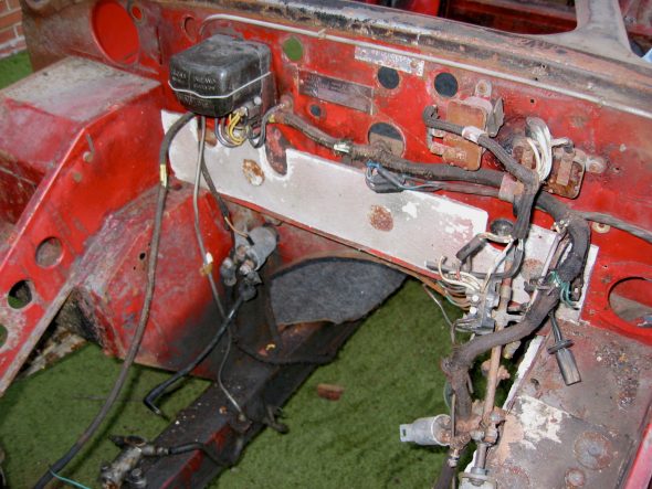
Wiring Harness – Carefully pulled the wiring harness from front firewall to the rear of the car. Approximately 10 screws through clips on frame. Also two screws and clips through asbestos insulation securing the harness.

Right wiring clamp

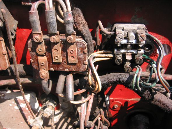
Voltage Box wiring

Wiring Clamps on Insulation 3

Firewall wiring clamp

Overdrive switch – Wiring connections: Left terminal – white/purple stripe. Middle terminal – 2 white/green stripe wires. Right terminal – 2 solid white wires. Bottom terminal – black wire from harness.

Firewall wiring harness

Overdrive relay

Relay wiring

Throttle Switch – Bottom terminal – white/ purple stripe wire. Top terminal – White/green stripe wire. See above.

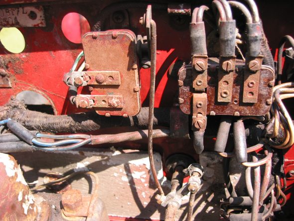
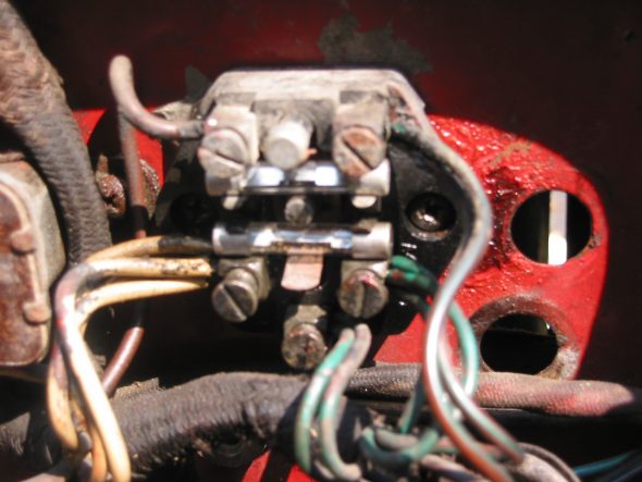
Fuse Block – After disconnecting the wiring to the block, two #10 machine screws were loosened to release the block from the firewall. 

Fuse Block wiring

Fuse Block and relay

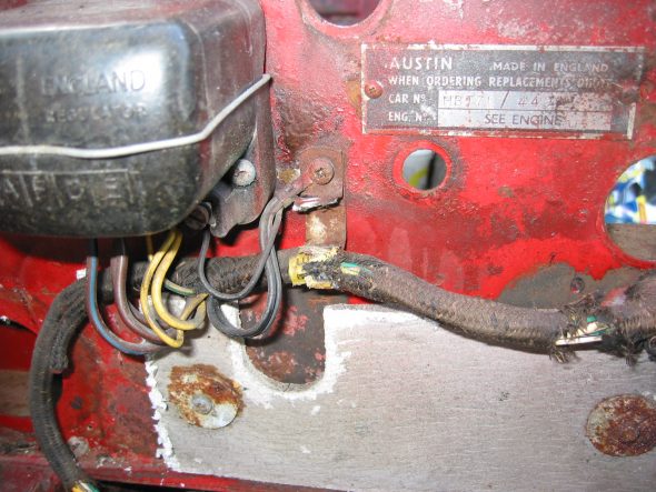
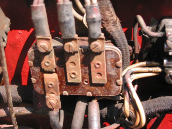
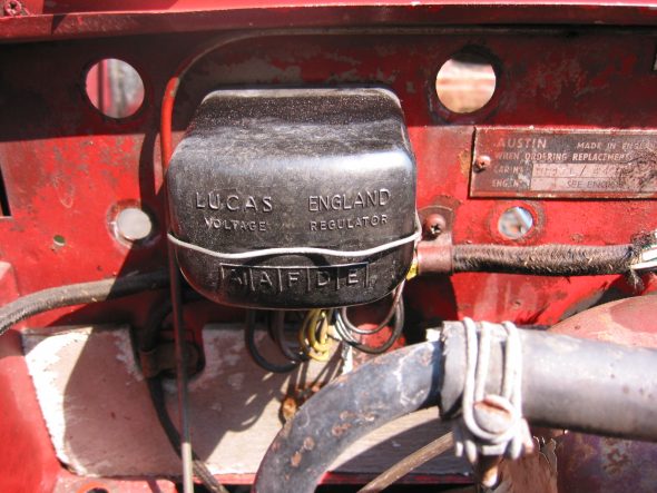
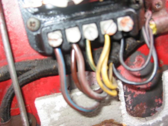
Voltage Regulator – Five terminals. Far left form driver’s perspective, labeled #1 with far left #5. 1 – black ground from adjacent screw. 2 – 2 solid yellow wires. 3 – 1 yellow/green stripe wire. 4 – 2 solid brown wires. 5 – 1 large brown/blue stripe wire. Note that there are three black ground wires to the adjacent firewall screw.

Voltage Box wiring

Voltage Box

Voltage Box (2)

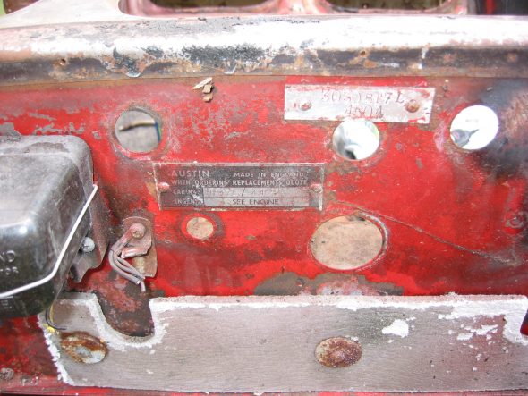
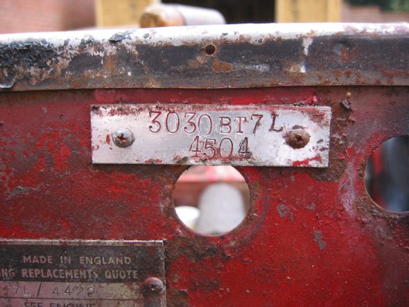
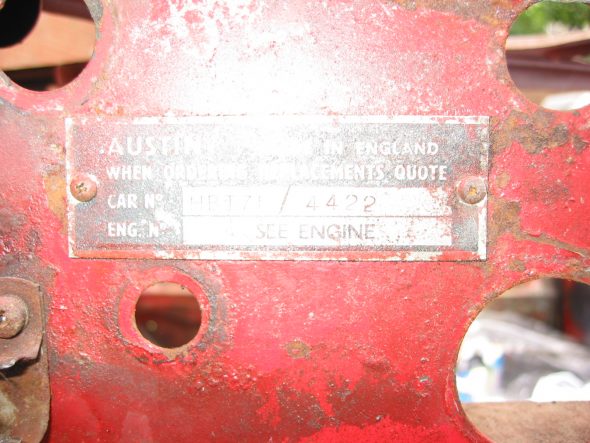
Number Identification Plates – from the firewall. Both are secured with small chrome sheet metal screws.

ID Plates 3

ID Plate 1

ID Plate 2

Throttle Linkage – Four 7/16” bolts holding shaft under tunnel. Very hard to get to. Disconnect at pedal linkage. Remove accelerator pedal – two large pozi-drive screws. Remove throttle shaft locator collar from engine compartment wall, two screws and nuts.

Throttle Linkage 1

Throttle Linkage 2

Throttle Linkage 3

Throttle Linkage 6

Throttle Linkage 5

Throttle Linkage 4

Throttle Linkage 7

Accelerator collar

Accelerator pedal to firewall