On November 21, 2023 we began to build the new electrical system for the Bugeye, all centered around the Classic Technologies Relay and Fuse Box. The new harness will be in three discreet sections: one for the bonnet, one for the central portion of the car including the engine bay and dash and one for the rear of the car. We will be incorporating a number of “personalizations” in the car that require modification of the original wiring.
The Bugeye is a very simple car and that extends to the electrical system. The initial design and production of the Sprite focused on keeping costs, and therefore selling price, to a minimum. So, there aren’t many bells and whistles on the car. Some of our “personalizations” are for safety, such as hazard flashers, and some are for comfort or ease of operation, such as interior courtesy lights. A list of these electrical system modifications is provided below. The list is followed by a more extensive explanation of these changes so that documentation is available for future owners.
Classic Technologies Fuse Box with seven relays, fifteen fuses with thirty-four wire connections, electronic flasher.
A panel was fabricated to fit behind the dash fascia to house toggle switches controlling the electric radiator fan, the driving lights, the dual selection fuel pumps (one SU and one Facet), and the interior and boot courtesy lamps. The panel also includes provision for a Lucas hazard light switch, a warning lamp for the operation of the driving lights, and a combination USB/digital voltmeter. Finally, the rheostat controller for the variable speed windshield wiper controller is also located on the panel. The switches on the panel are accessible but hidden from view.
Bespoke wiring harness utilizing Deutsch connectors to permit the quick and easy removal of the dash with all gauges and switches in tact
Alternator to replace the generator (dynamo) and external voltage regulator
Radiator electric fan
Hazard switch and lights
Driving lights with operating warning lamp
Variable speed wiper controller
Speed Hut electronic GPS speedometer and tachometer
LED interior gauge lamps, flashers, side and tail lights and brake lights
LED interior footwell and boot courtesy lights operated by a key fob with a forty second operating delay and a manual override toggle switch
Radio Shack buzzer serving as a turn indicator switch alarm
Dual redundant fuel pumps selected by toggle switch
Modified original windscreen washer pump
And now for some additional detail:
Classic Technologies Relay/Fuse Box
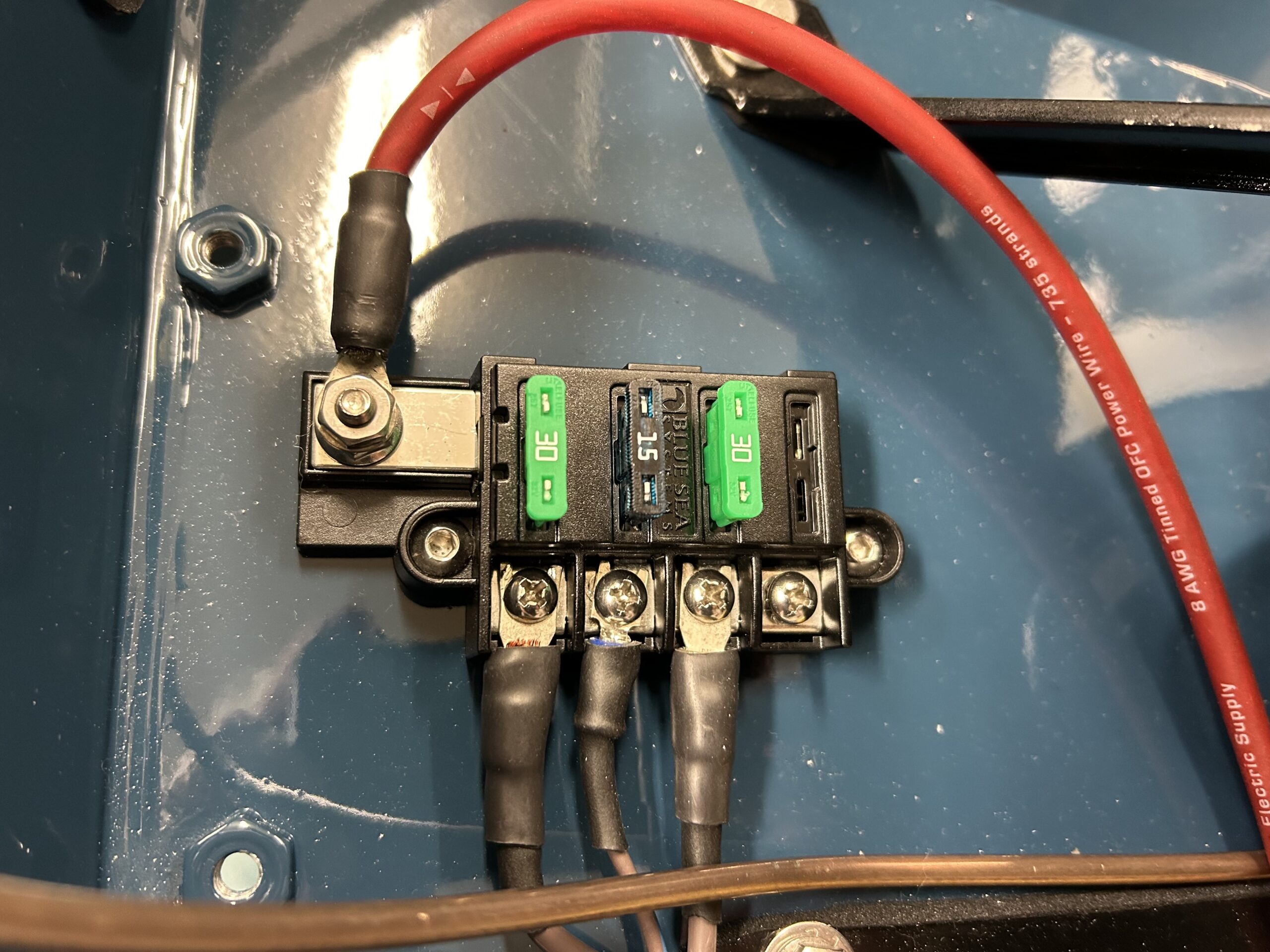
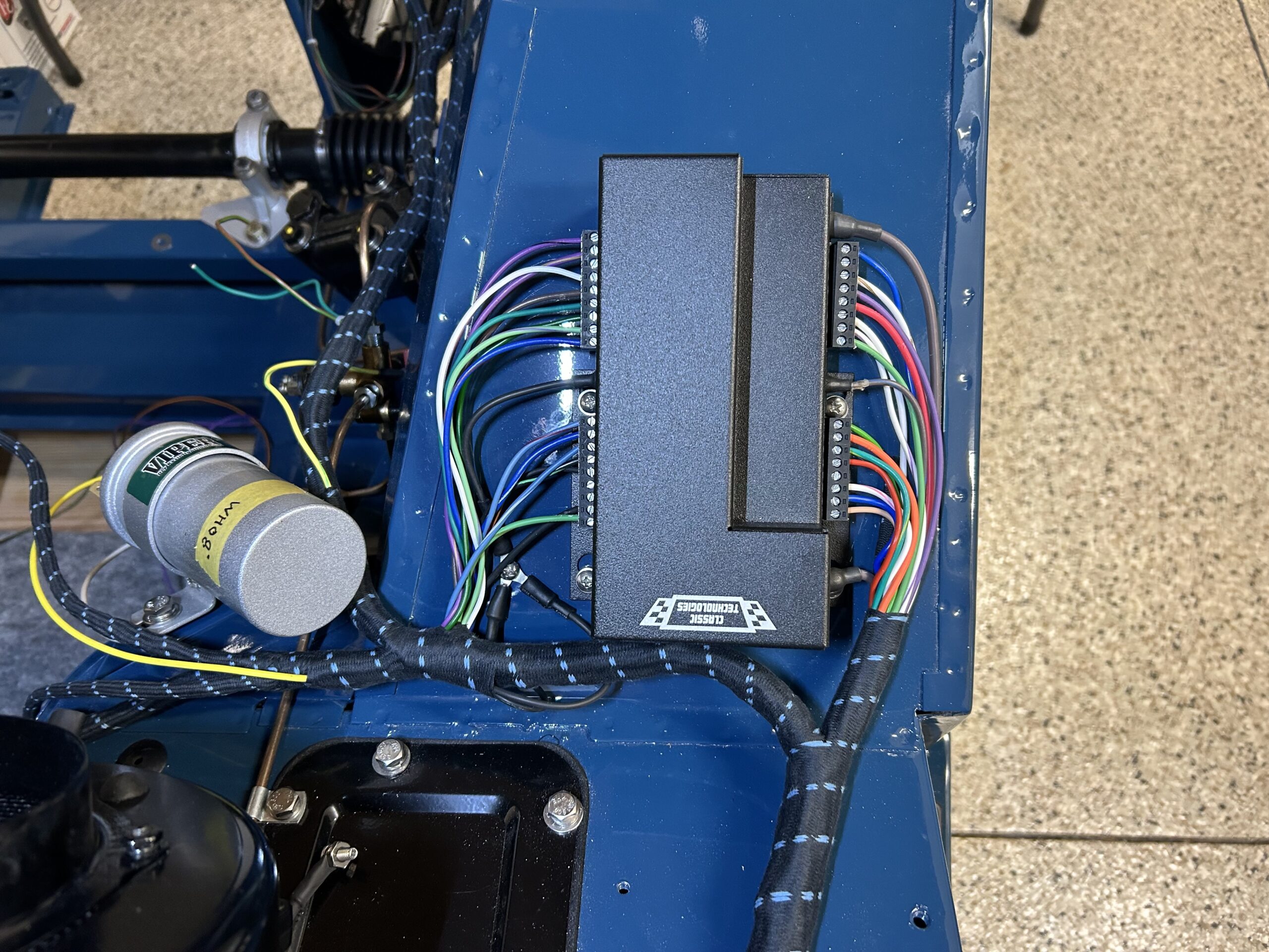
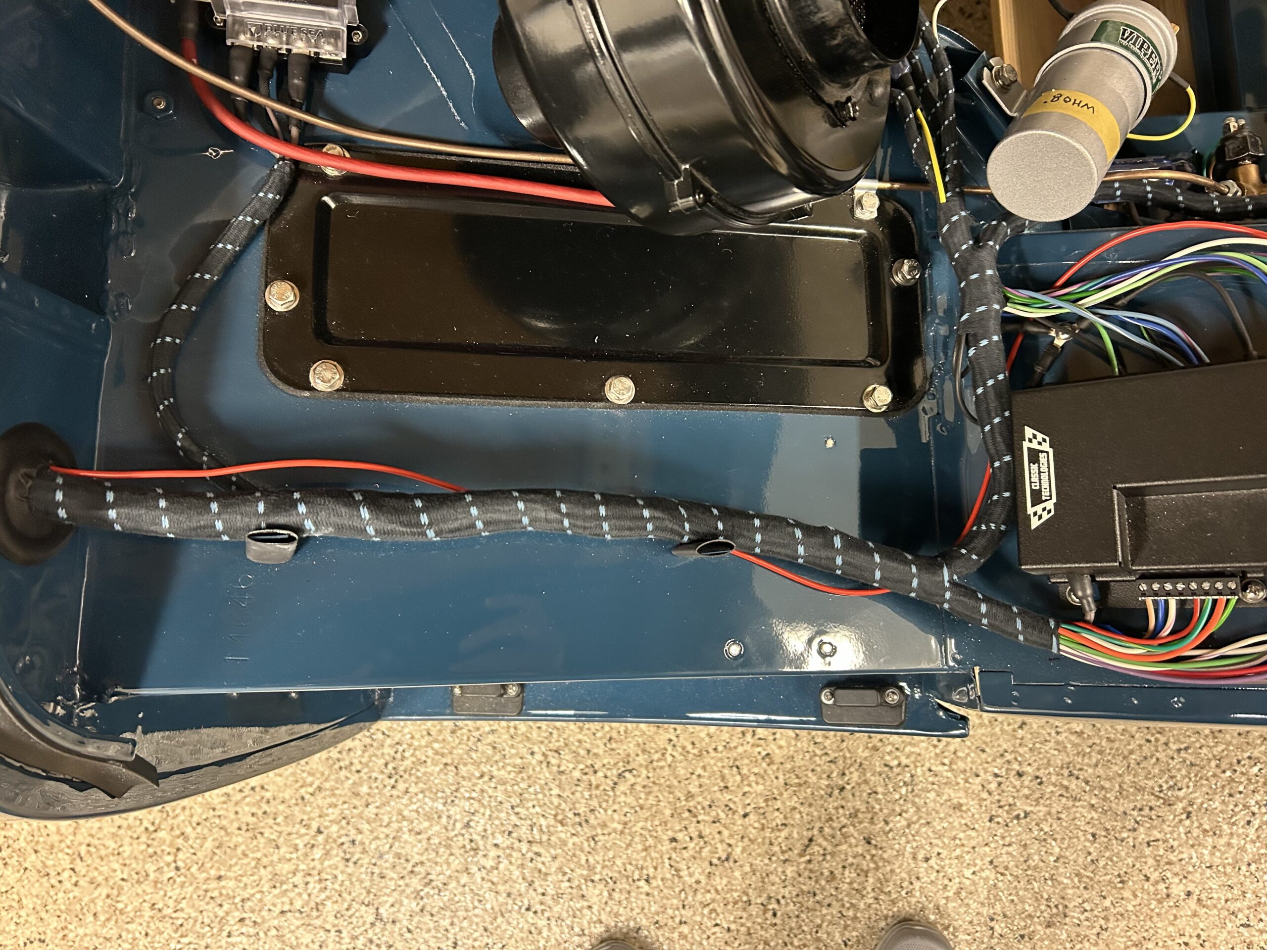
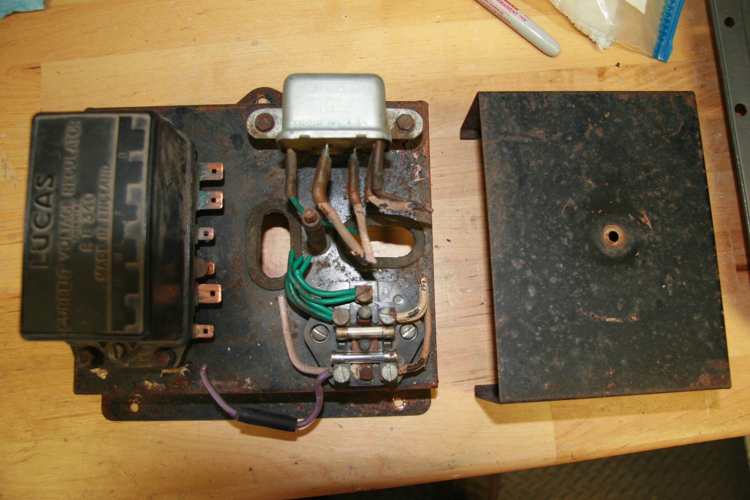
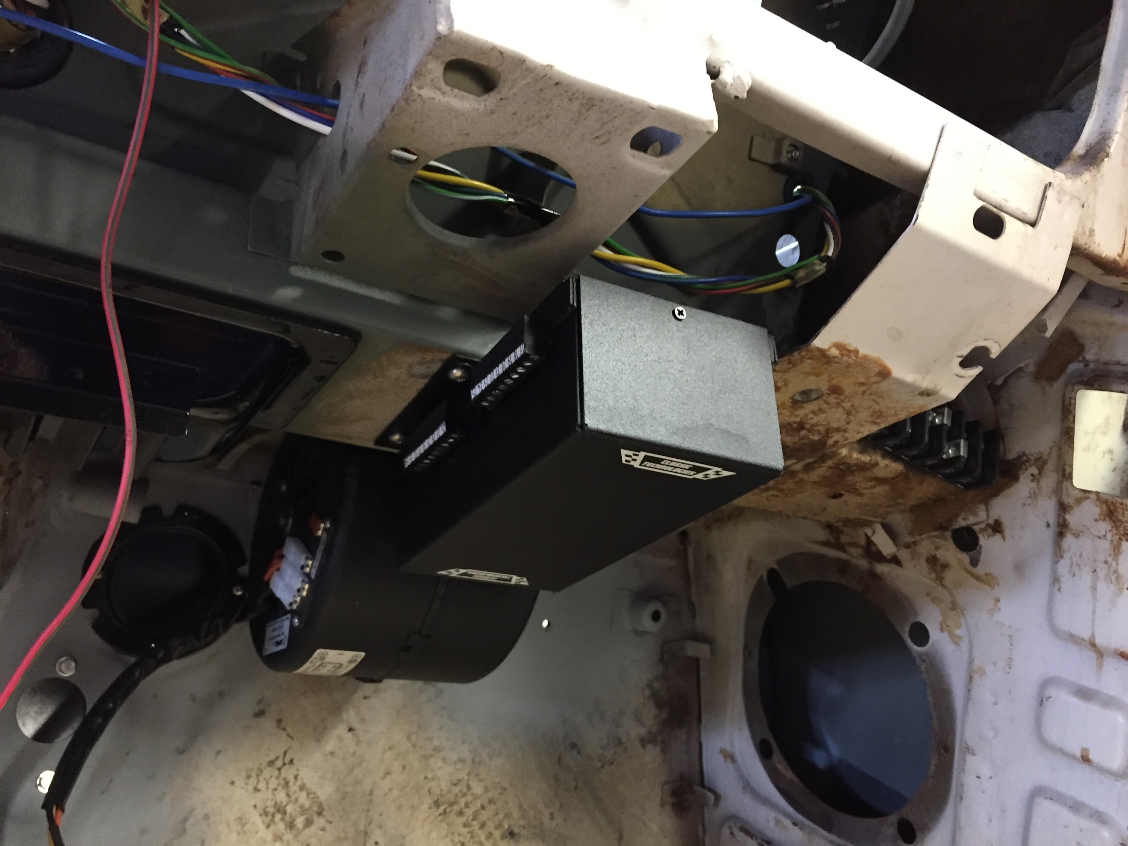
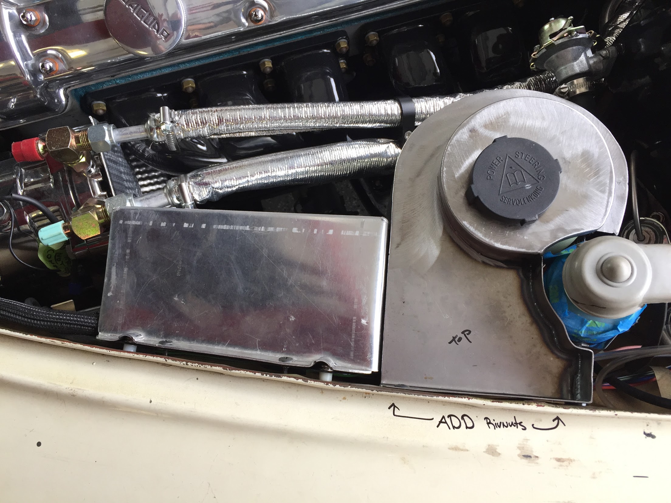
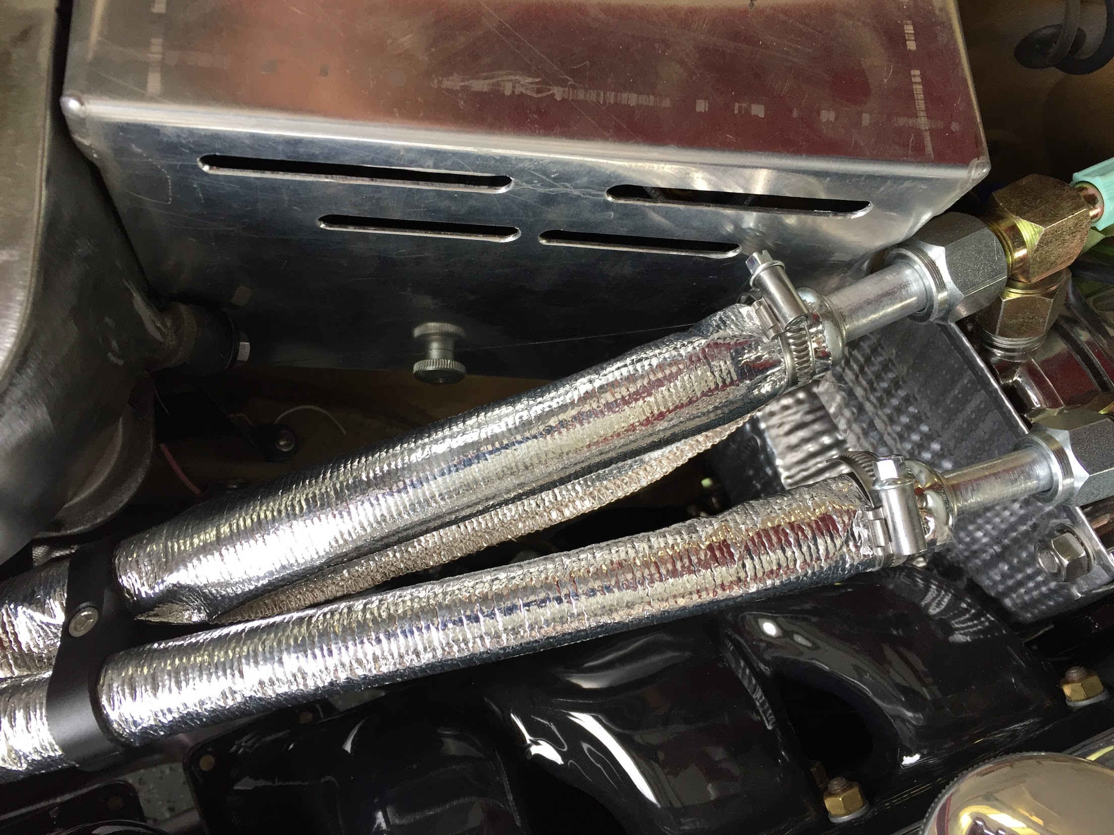
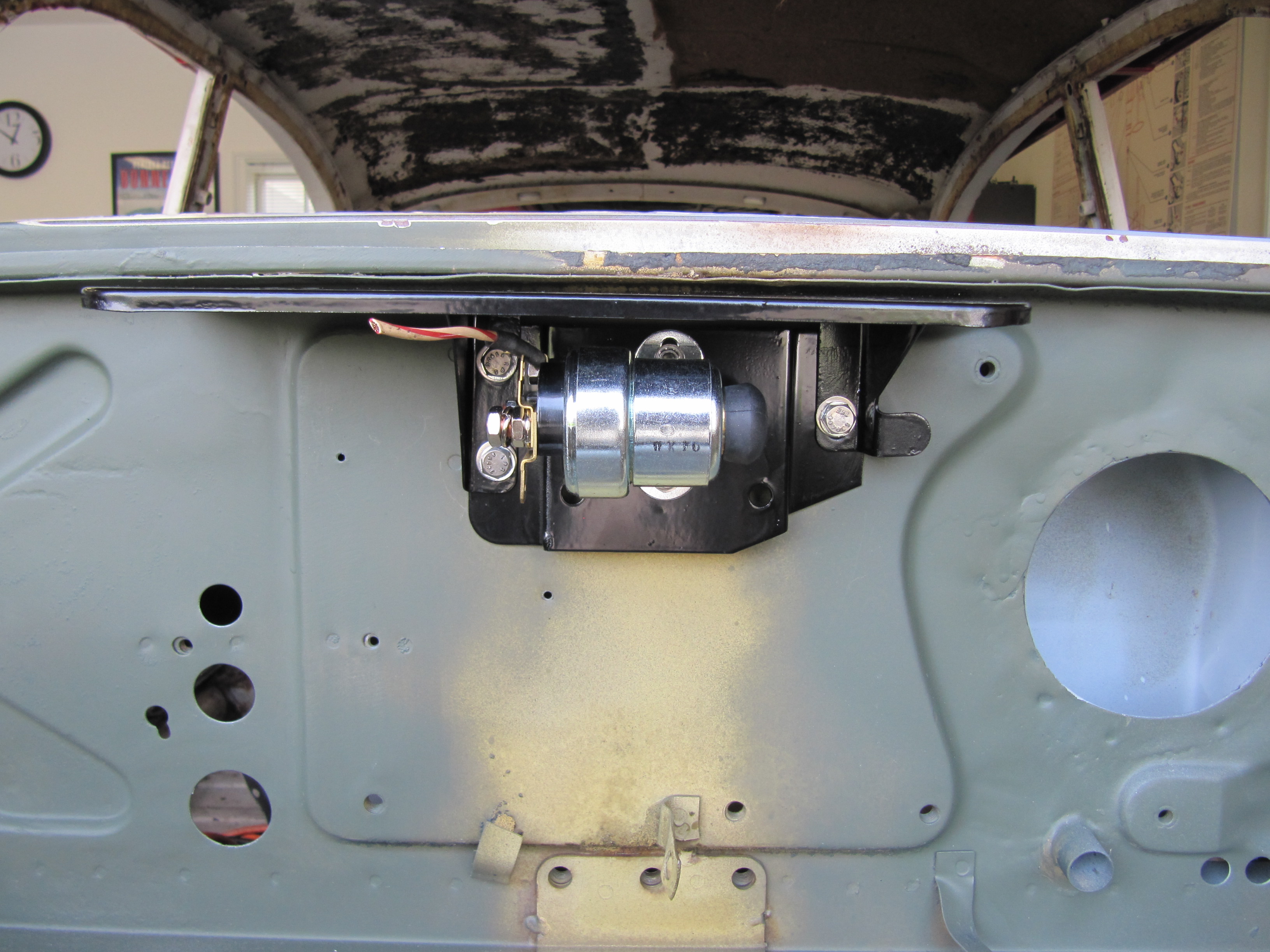
We upgraded from the original Model SF6 fuse unit with the two glass fuses of 35 amps and 50 amps to a modern fuse/relay panel supplied by Marc Goldblatt, owner of Classic Technologies. http://www.classic-technologies.com We have chosen to locate the box on the RH fender valance where the original regulator was secured to the car. We installed four rivnuts in the valance to make mounting the box a simple task.
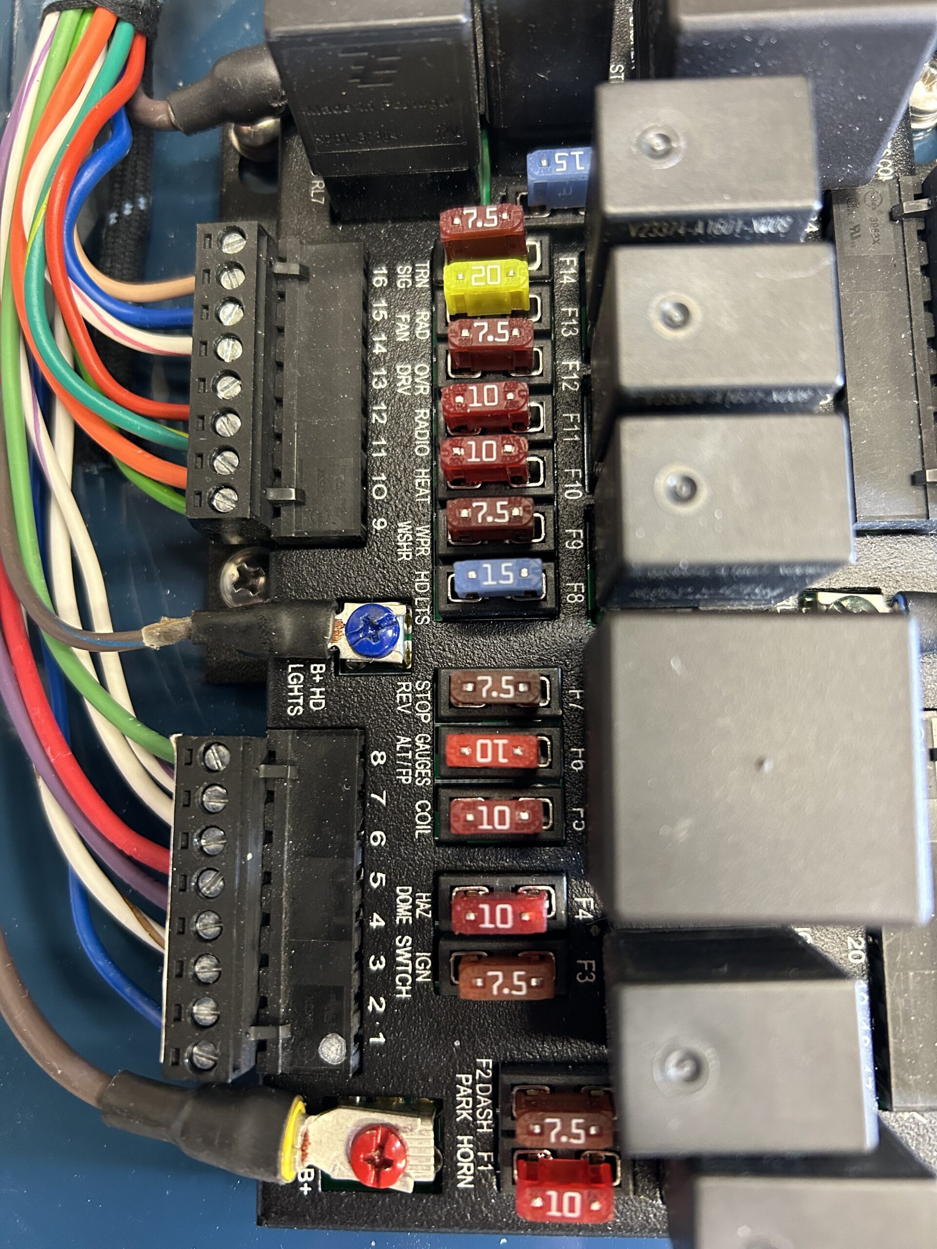
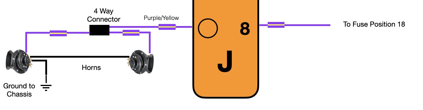
The Classic Technologies fuse/relay panel provides for 15 fused circuits with 34 pin connectors, 7 relays including horn, ignition power, fog lights, high beams and low beams headlights, starter and accessory power and 2 flashers for the turn signals and hazard lights. We selected the optional flasher relays for LED lights.
The Classic Technologies panel is only 6 3/4″ (171mm) long X 4 5/8″ (81mm) wide X 2 3/16″ (56mm) tall. The lug-less terminations into unpluggable connectors are another nice feature making the installation of the panel easy and convenient. A poster size color schematic was provided along with a clear instruction manual to guide hobbyists like myself through the installation. We also decided to purchase all of the wire from Marc. It doesn’t match the original wire as available from British Wiring, but it is close. Marc will provide additional support if needed.
Fuse/Relay Panel Design Theory
The 15 fuses are broken up into three groups:
- Constant Power: Fuses F1 through F4, F8, and F15. These fuses are tied to the battery + terminal (B+). Examples: Courtesy Lights, Parking Lights, Hazard Flashers, and Horn. These features have power regardless of ignition switch position.
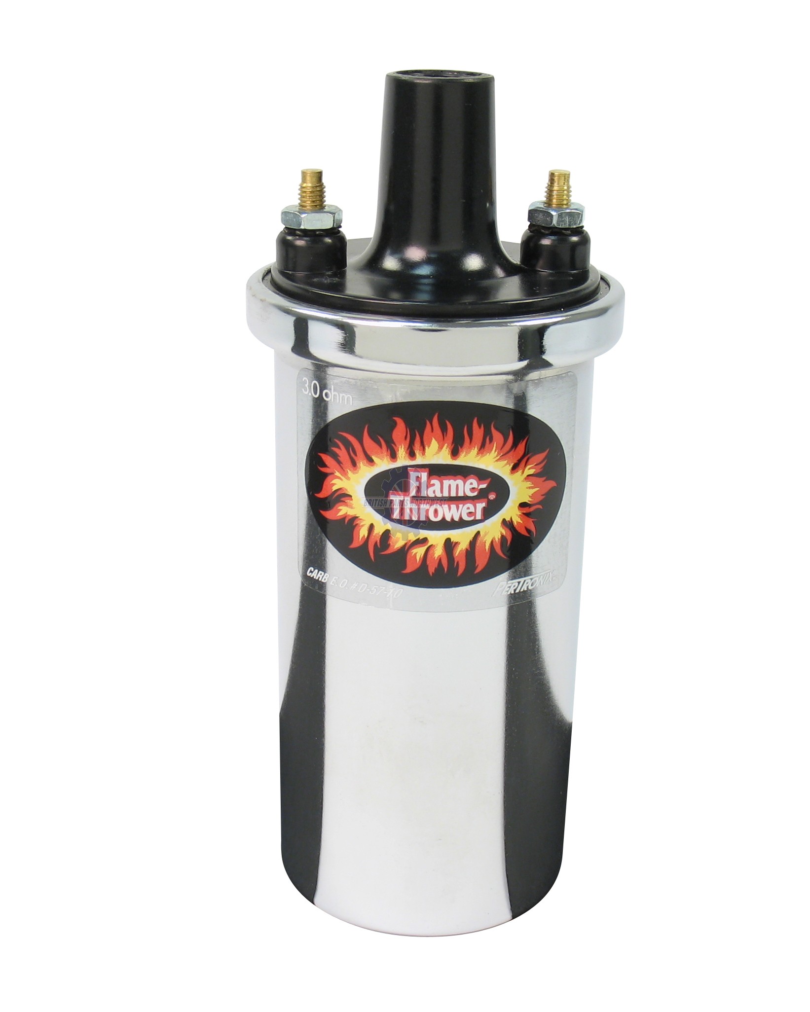
- Ignition Power: Fuses F5, F6, and F7. These are items that are critical to starting the car that should have power while the car is being started. Examples: Coil, Alternator excitation, Fuel Pump, Gauges/Warning Lights, brake lights.
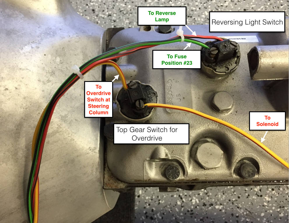
- Accessory Power: Fuses F9 through F14. These are items that are not critical to starting the car and should not have power while starting the car to maximize power to the starter. Additionally, in order to prevent battery drain, these items should not have power when the keys are removed from the ignition. Examples: wipers, heater motor, turn signals, overdrive, radiator fan, radio, reverse lights…
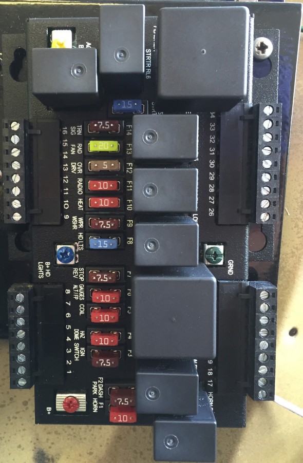
Classic Tech Fuse Box
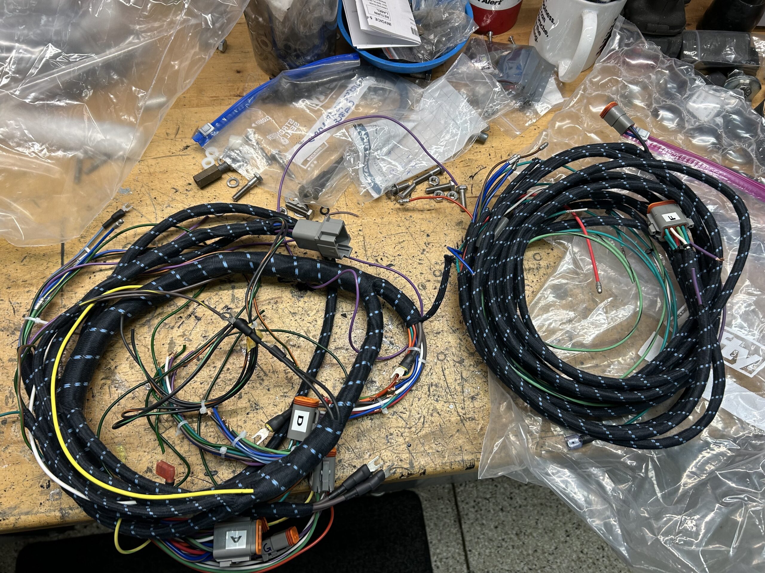
Bespoke Wiring Harness
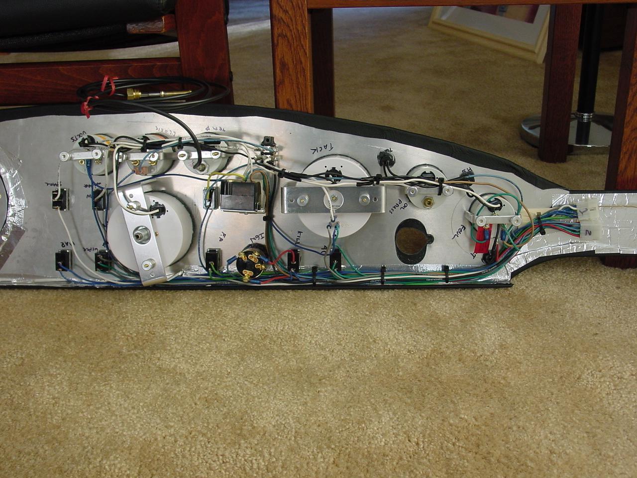
The impetus behind building a custom wiring harness was the desire to have the ability to install and replace the dash with all of the switches and gauges in place. Anyone who has laid on his back on the floor of the car and under the dash appreciates the motivation to pursue this approach. A friend who owns a Cobra shared what he had done and it was a model for exactly what we were after.

Cobra Dash
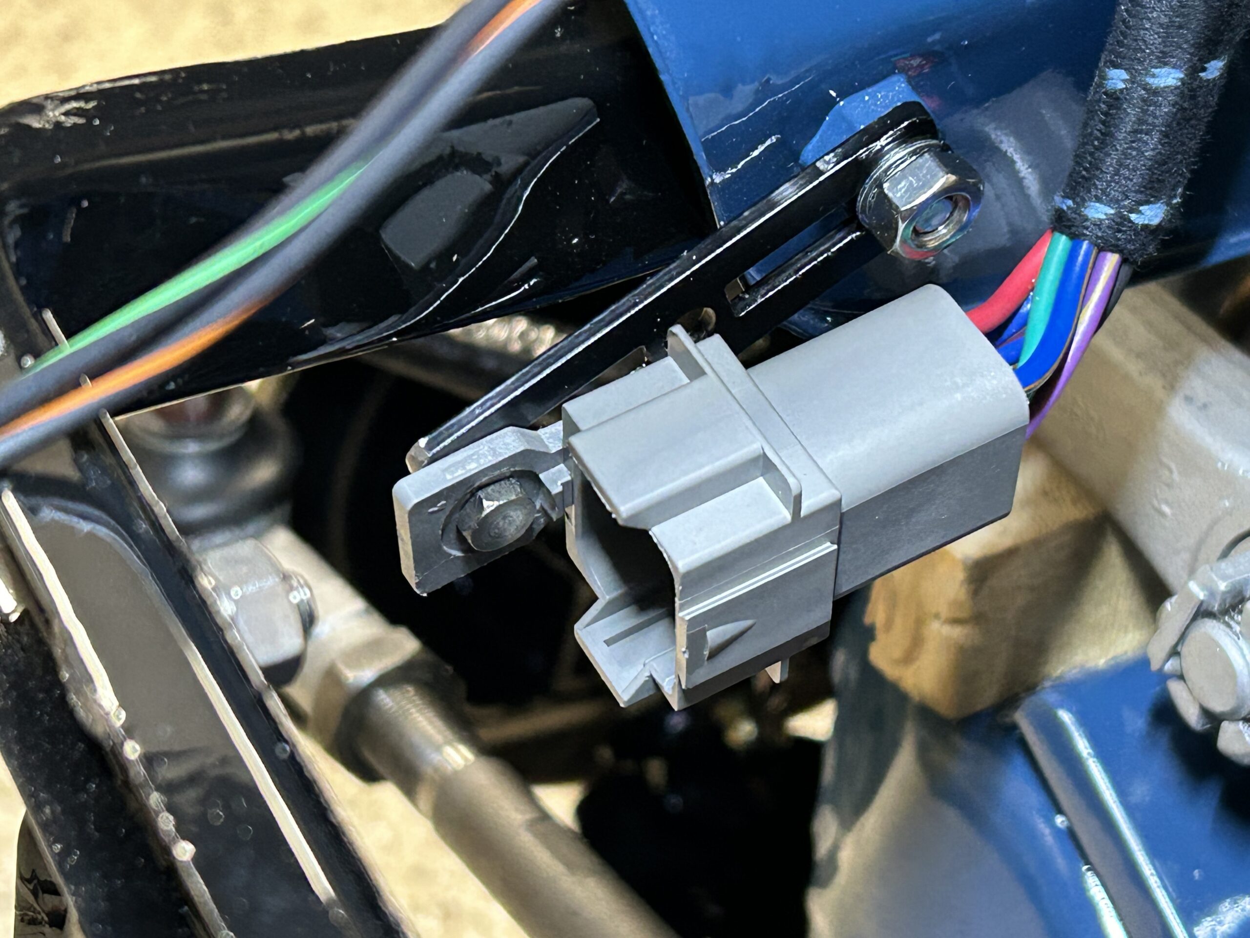
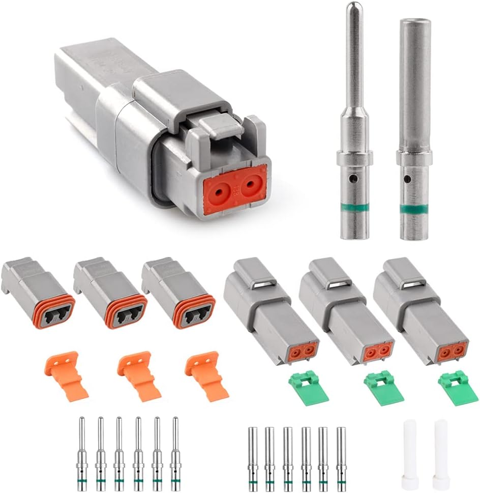
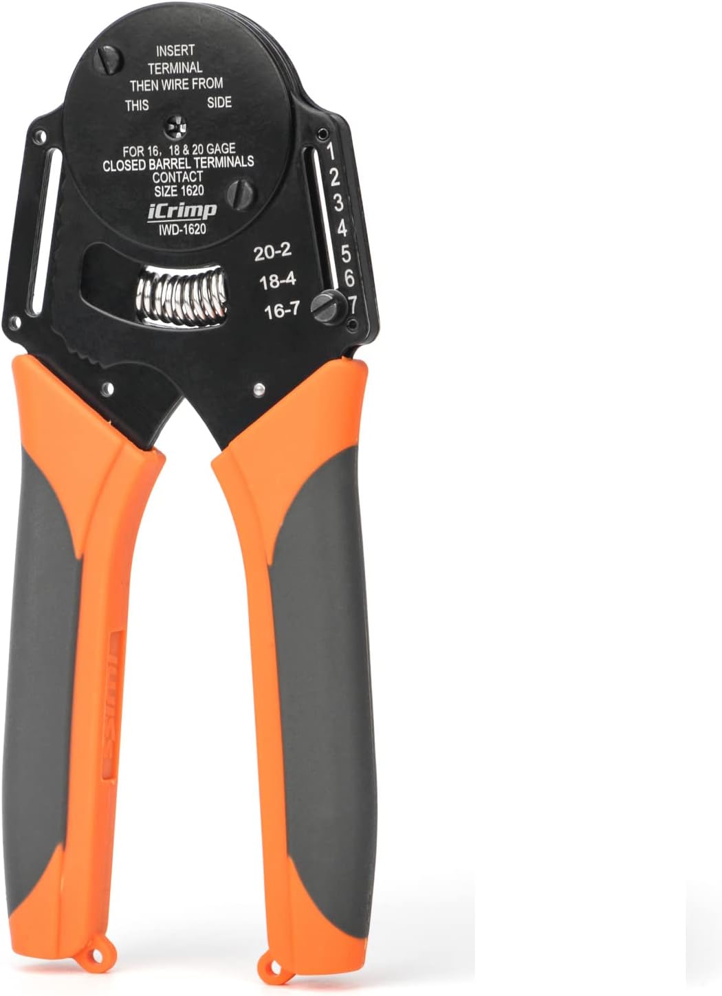
Note the Molex connectors on the right side of the back of the dash. In our case we chose to utilize deutsch connectors. These are water tight plastic connectors. One can use traditional wire pins that crimp over the wire end or one can use “solid barrel contact” terminals with a special crimping tool. We recommend the solid barrel type. We picked up these items from Amazon supplied by JR Ready. The connectors come in various sizes from two wires up to twelve in each connector. The connectors are extremely easy to use and provide a superior result. This is a sample kit as provided by JR Ready. A special purpose crimper is used with the connectors. It is inexpensive and does a super job.

JR Ready Deutsch Connectors
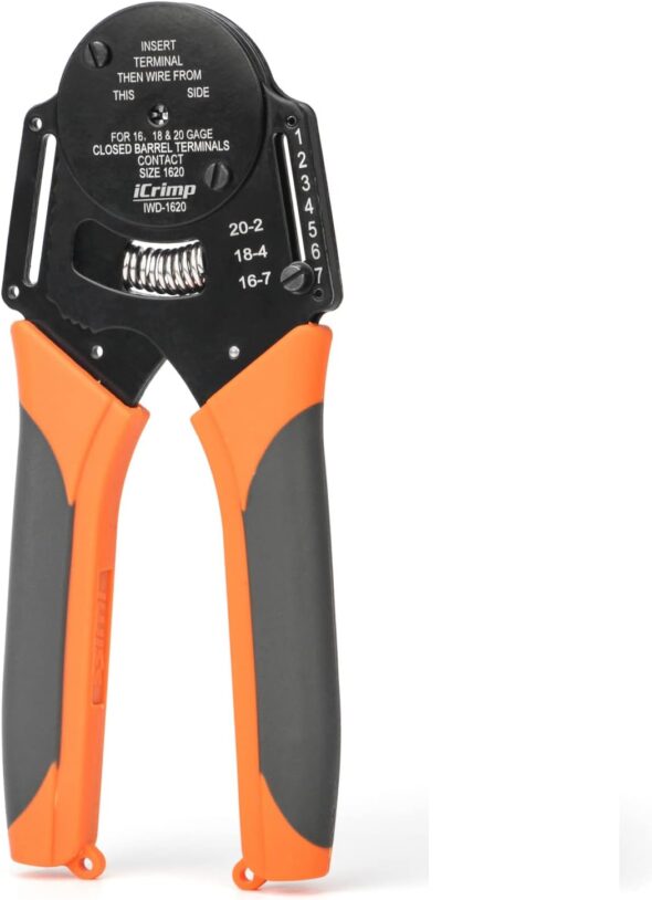
Deutsch Connector Crimper
This is the finished result after crimping the terminal on the wire:
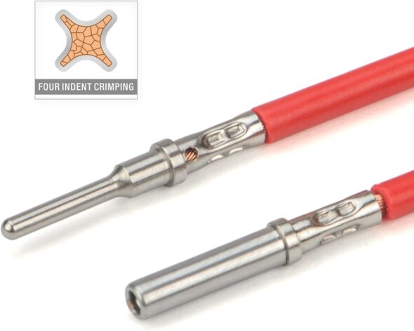
Four Indent Crimping
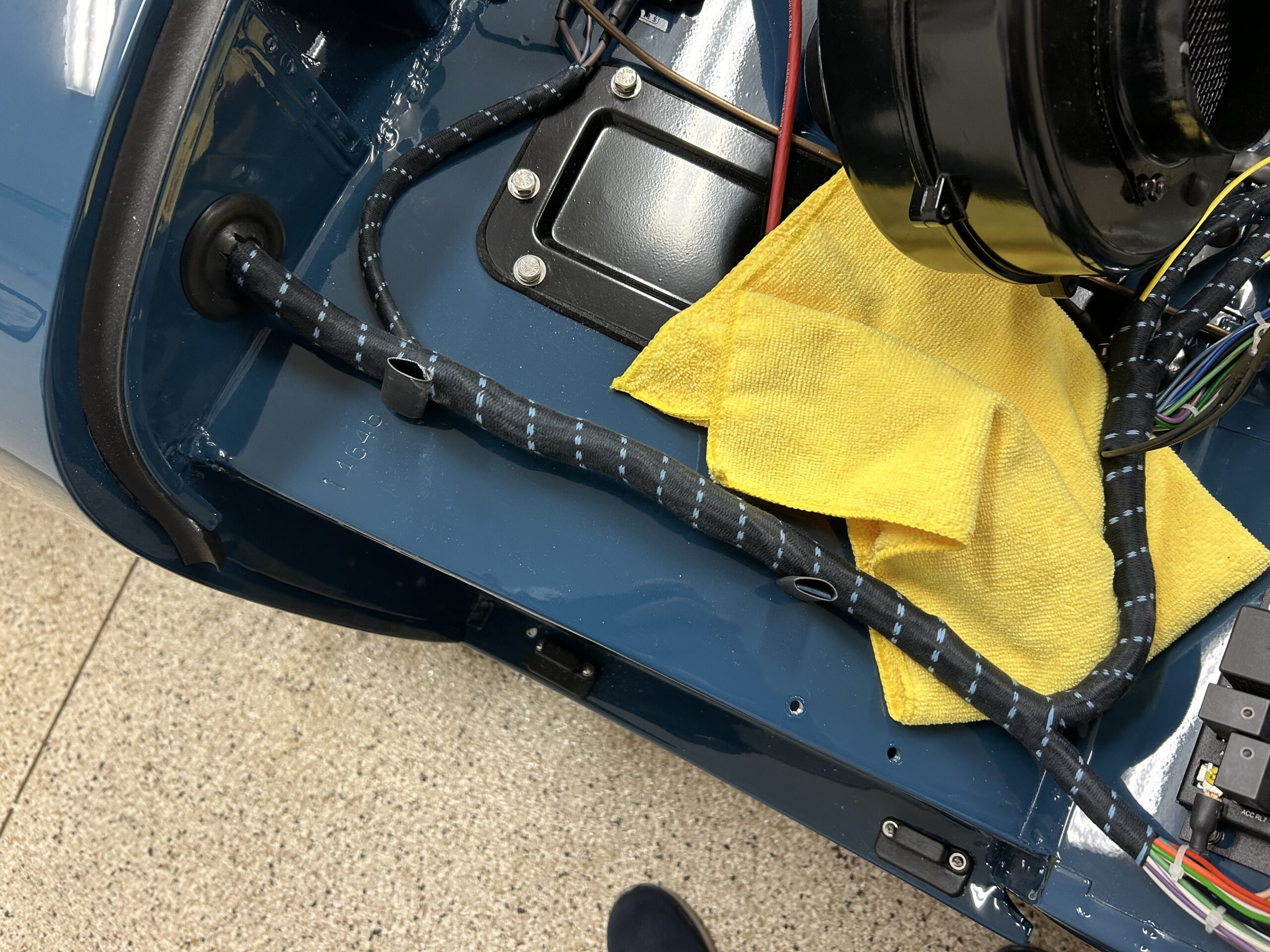
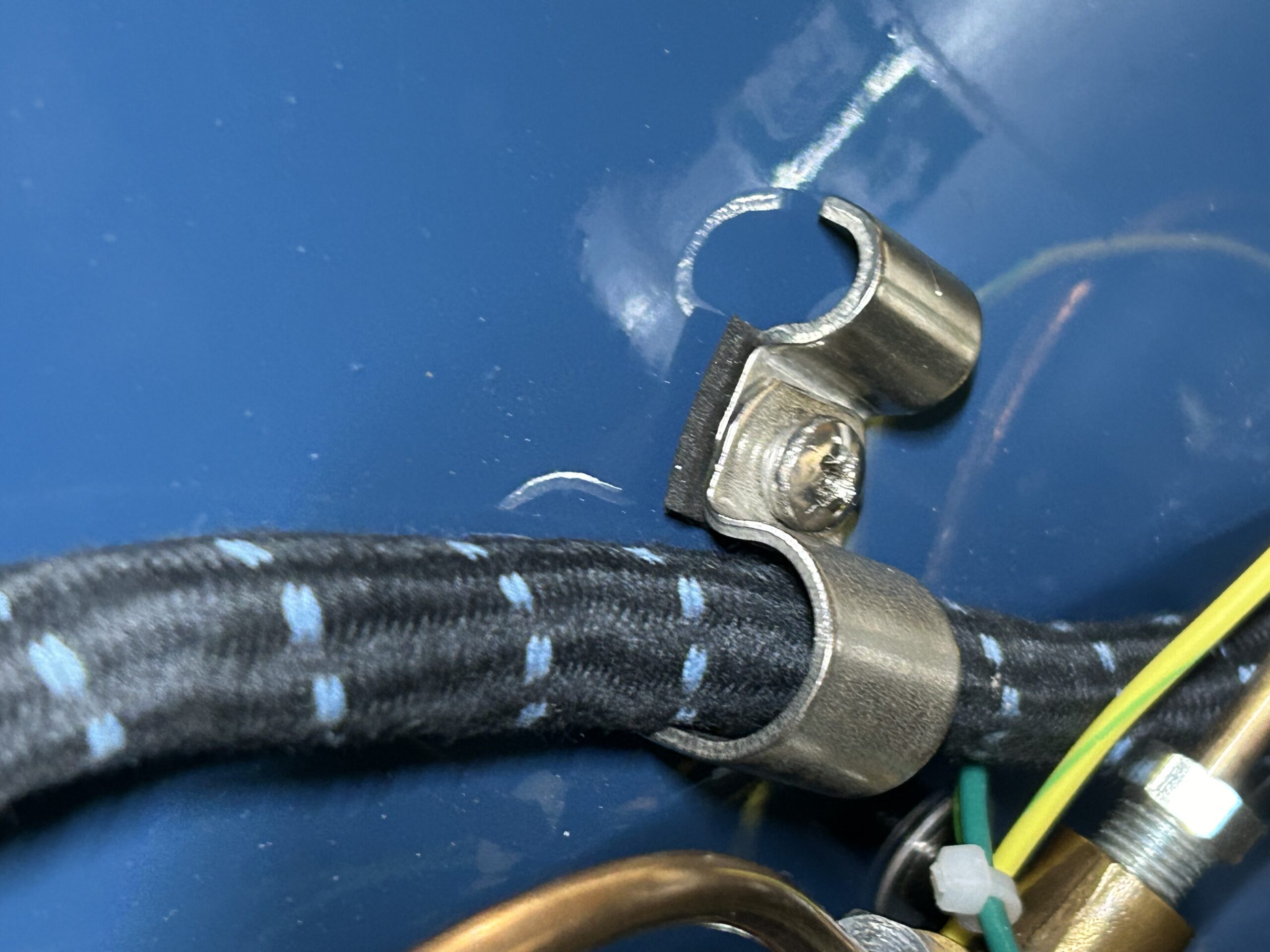
As we built the wiring harness wires were gathered together and organized with small zip ties. Once all of our wiring was tested the zip ties were replaced with Tesa electrical tape and then the final harnesses was sent to Rhode Island Wiring to cover the harness with a braided cloth cover appropriately color coded for the Austin-Healey Sprite.

Tesa Harness tape
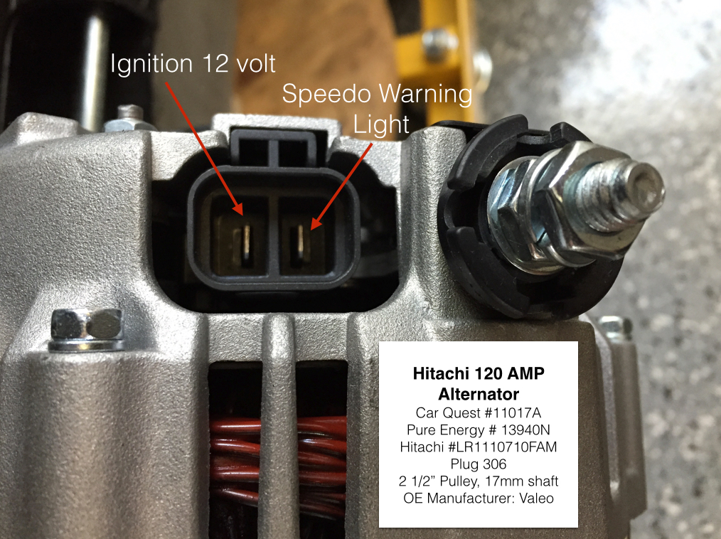
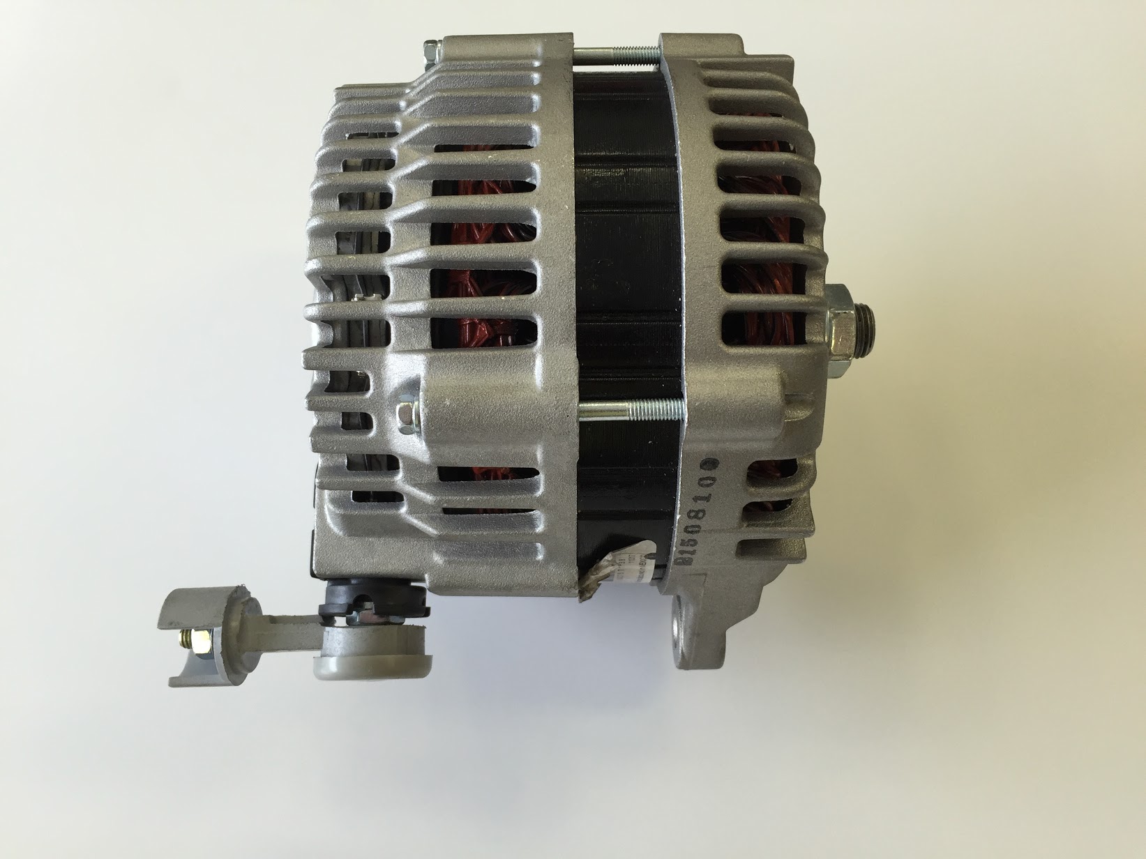
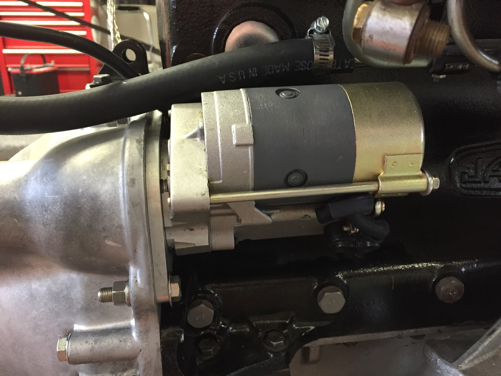
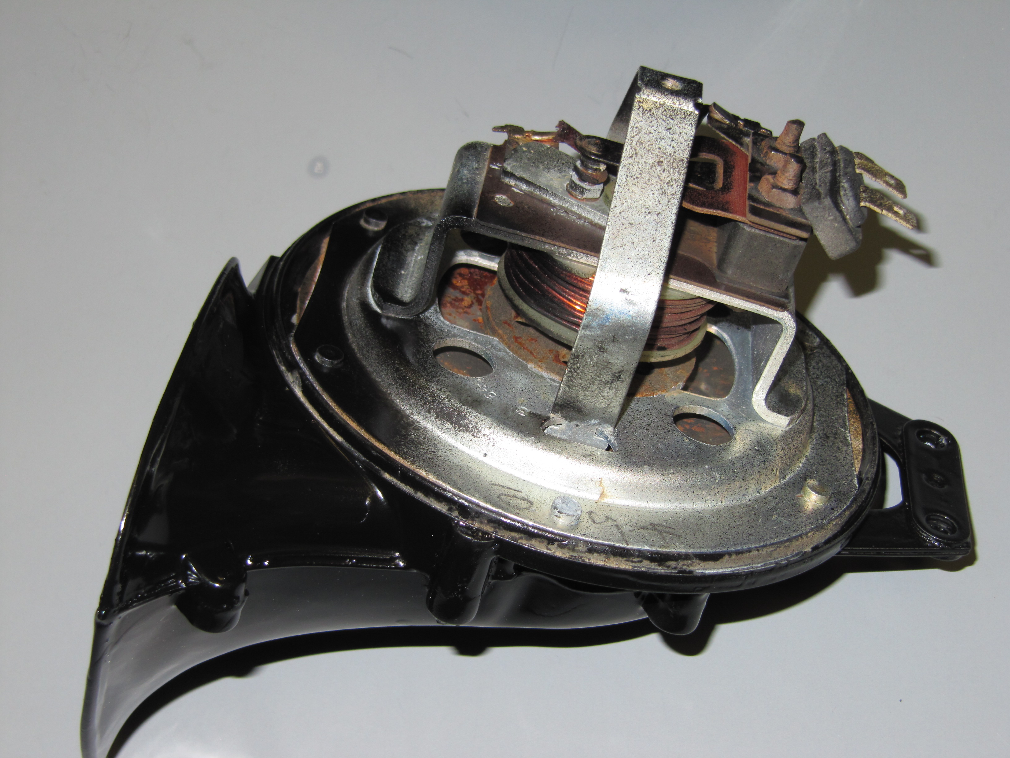
Alternator
The only information we have on the alternator is that it is a rebuilt unit designed to replace the Lucas alternator that we had in the car previously. It is rated output is 65 amps.
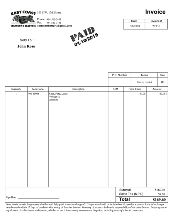
Alternator Invoice
Hazard Switch and Lights
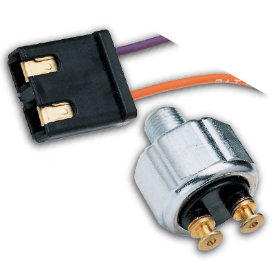
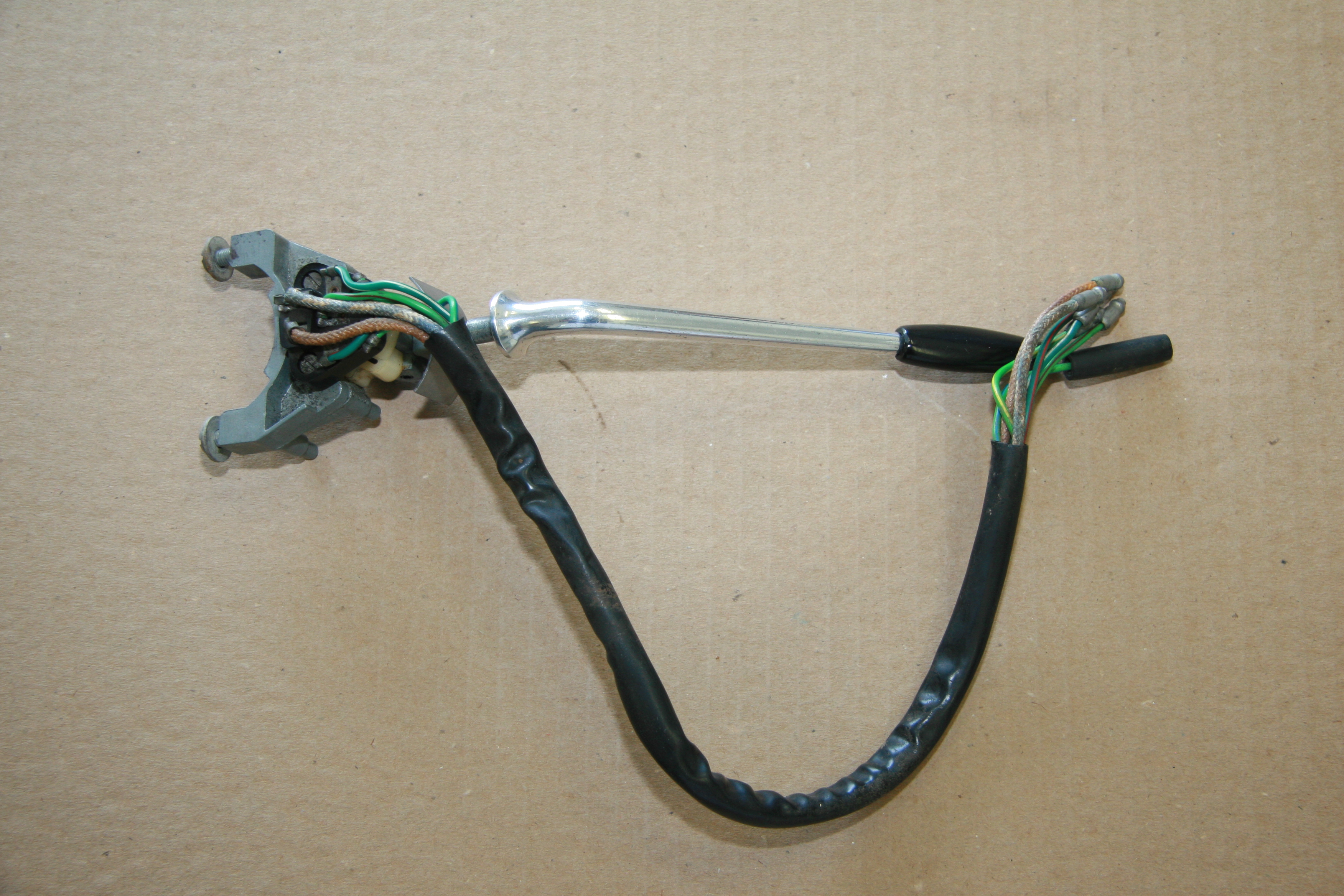
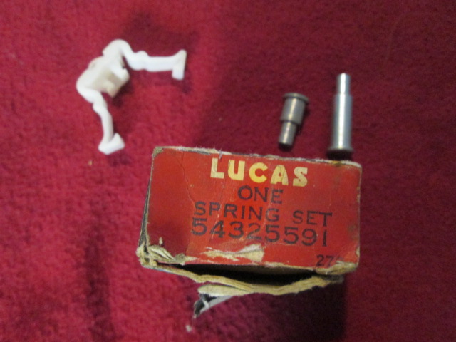
Of course, the Bugeye did not come equipped with hazard or caution lights. However, in today’s world and particularly with such a small car, hazard lights are really essential. The Classic Technologies relay/fuse box incorporates a hazard flasher relay system. We purchased a Lucas 155SA hazard switch to activate the system.
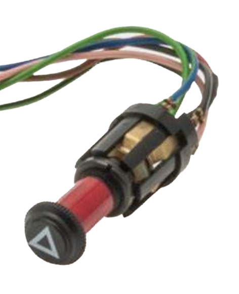
Lucas Hazard Switch
The switch is a push/pull type and incorporates a flashing warning light in the body of the switch. The switch will be added to the dash panel we built and is installed behind the dash.
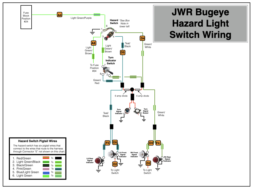
The Lucas 155SA hazard switch was used in many British cars, and apparently the one we ordered was used in the 1974-75 triumph TR6 and the 1973-77 Triumph Spitfire. Unfortunately, the color of the wiring leads from the switch terminals did not match any of the Triumph wiring diagrams that we could locate online. Establishing the proper wiring pattern to make the turn indicators and the hazard flashers work as they should involved a great deal of trial and error and considerably more time than anticipated. However, at the end of the day we were successful. The chart below shows the transition from the pigtail wire colors to the wiring used in the Bugeye as we wired the car.
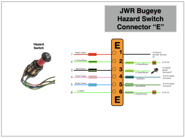
Hazard Switch Wiring Schematic
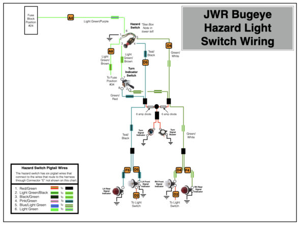
Hazard Light Switch Wiring System Schematic
Driving Lights with Operating Warning Lamp
We have decided to not install the reproduction Lucas 576 driving lights on the Bugeye. However, we have wired the car for the easy addition of the lights at a later date should we want to add them. These lights were used on the Sebring Sprites prepared by Donald Healey for the endurance race.
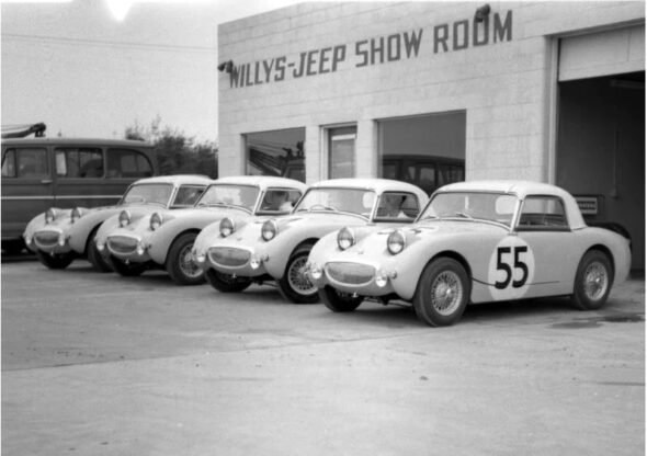
Driving Lights on Sebring Sprites
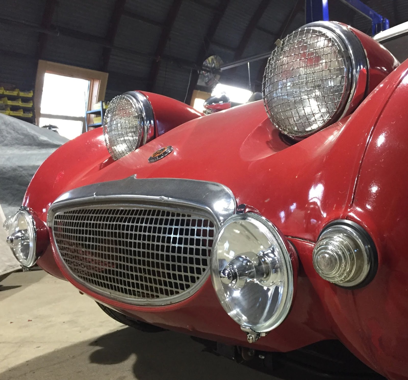
The lights may be sourced from Bugeyeguys.com. Installing the lights does require drilling two holes in the front of the bonnet. This is an image of the lights as installed on a Bugeye (not mine) showing the relative position of the mounting to the crease in the bonnet.

Sebring Driving Lights
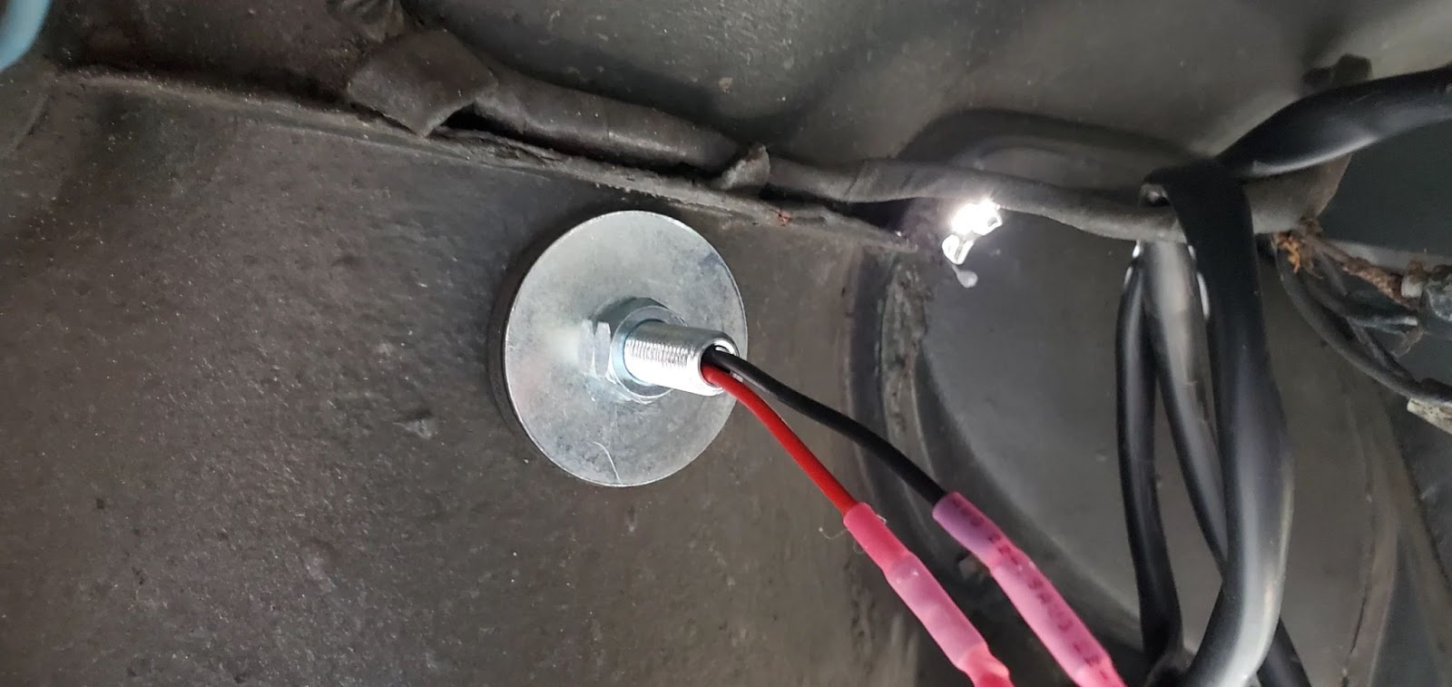
And, here is a view from the inside the bonnet

Driving Light Mount Inside View
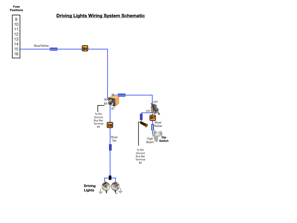
Our wiring scheme is shown below. The lights are activated by a toggle switch behind the dash and we incorporated a warning lamp as well. The switch is powered by a connection to the high beam terminal of the dip switch so they can only be activated when the high beam lights are on. A dedicated bosch relay was added for the driving lights and was located on the wood support block behind the dash grab handle.
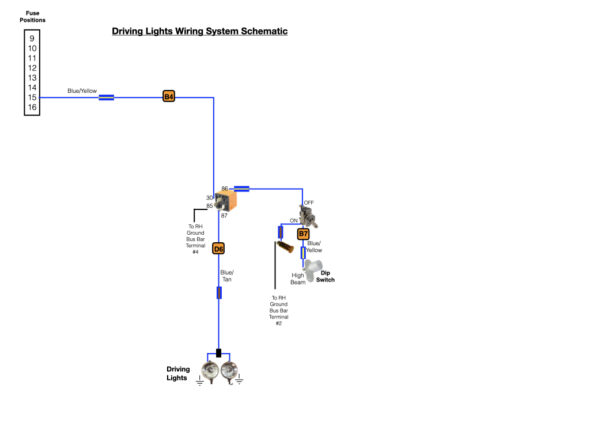
Driving Lights Wiring Schematic
Variable Speed Wiper Controller
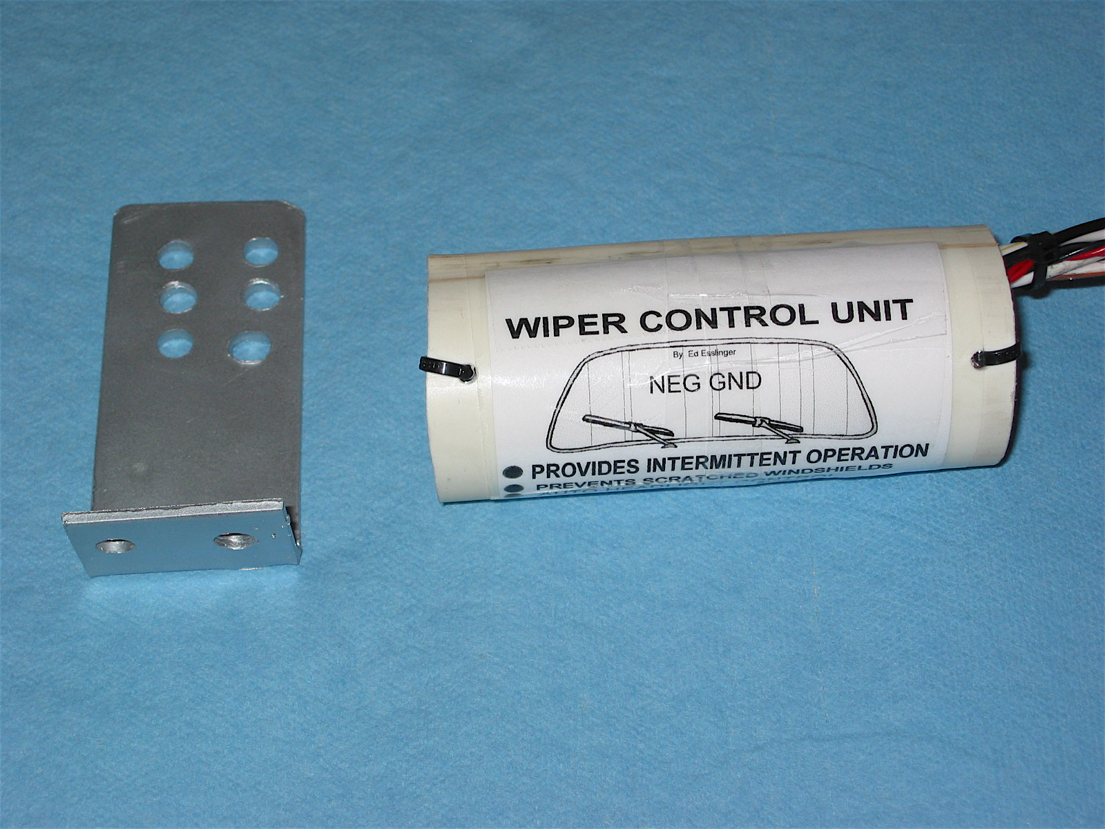
Some years ago Ed Esslinger authored an article on a Sunbeam Tiger web site about a kit he put together to provide unlimited variable control of the speed of the Lucas wiper motor. We tried one of his kits on the Big Healey and liked it. Great for handling mist and light rain. Unfortunately it doesn’t make the wipers go any faster!
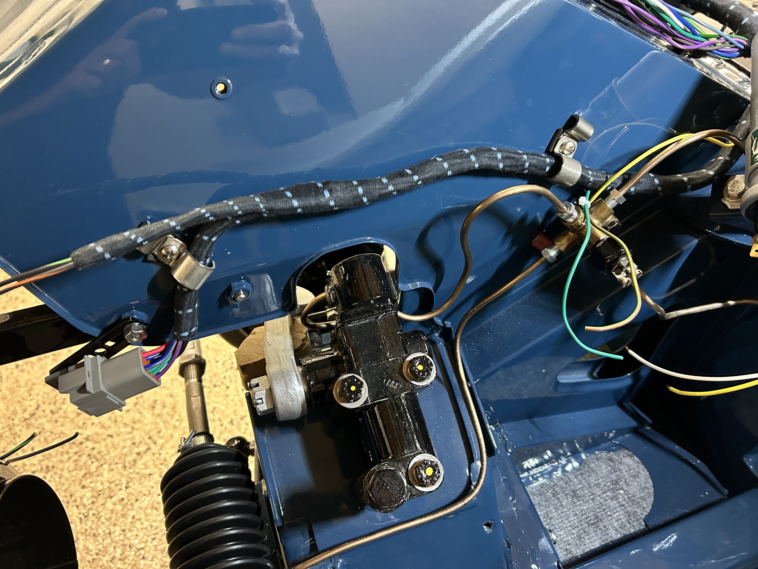
We installed the control knob for the variable speed rheostat on the vertical panel we made and installed behind the dash. We took advantage of the blanking bolt nuts intended for the steering column bracket in a RH drive car as a location for mounting the controller electronics. No holes were drilled in the chassis. This is the instruction sheet provided with the kit: https://valvechatter.com/wp-content/uploads/2012/07/Wiper-Control.pdf
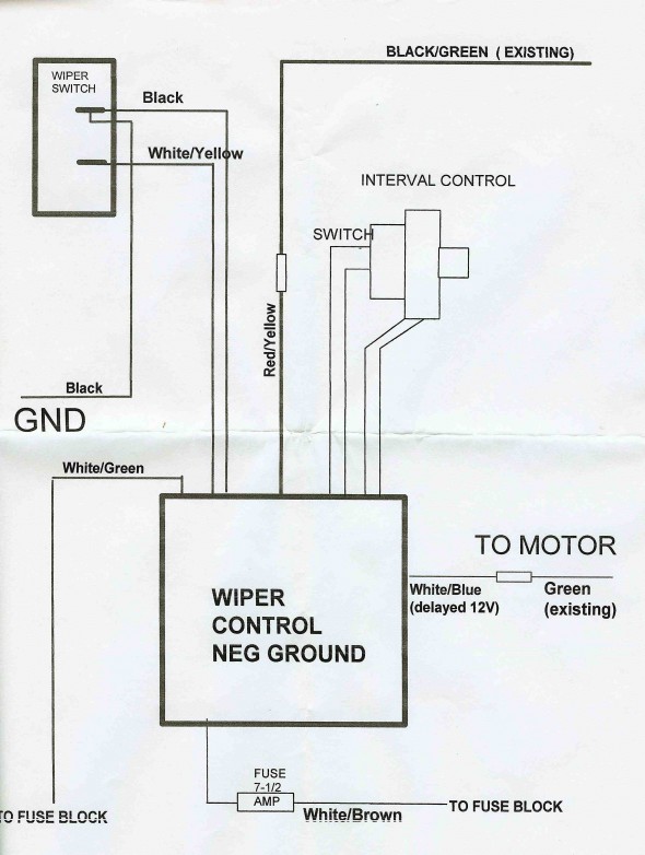
Wiper Interval Controller

WIPER CONTROL UNIT
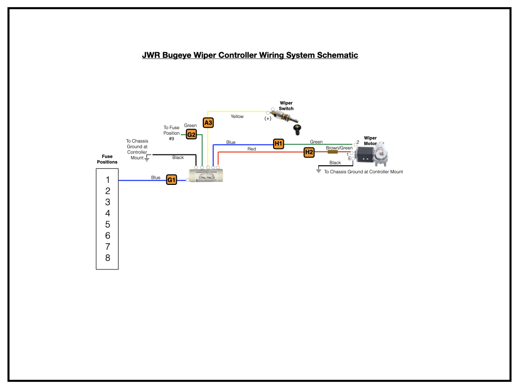
The following image illustrates the actual wiring in the Bugeye using the Classic Technologies Relay/Fuse Box:
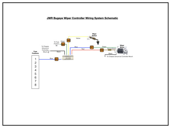
JWR Bugeye Wiper Controller Wiring System Schematic
SpeedHut Electronic GPS Speedometer and Tachometer
We had experienced problems with the speedometer feed from the Datsun 5 speed gearbox in the past. There is very little room in the gearbox tunnel to properly align and tighten the speedometer cable into the gearbox fitting, so we decided to “upgrade” to an electronic GPS speedometer. Both the speedometer and tachometer were sourced from Bugeyeguys.com although they are made by SpeedHut. David, at Bugeyeguys, had gauge faces made for the SpeedHut units to make them look like the original Smiths gauges for the Sprite.
The speedometer and tachometer are designed to be used together and take advantage of mini-connectors to link the gauges together. The speedometer has a red/black wire that is connected to constant battery power and in our application the wire is spliced into a green wire and routed to fuse position #5 through deutsch connector C6. Switched power is provided to the fuel gauge, the speedometer and the tachometer with a red wire routed to fuse position #13 through deutsch connector B5.
The white wire for the speedometer and tachometer gauge lights is joined with the white wire from the power inverter and is then connected to the panel lamp switch.
The blue wire from the speedometer provides power to the high beam warning light in the speedometer and is routed through deutsch connector D2 to the high beam terminal of the dip switch. When the high beam lights are triggered a red LED light illuminates on the face of the speedometer gauge.
The black wires from the speedometer, and the tachometer are joined together and connected to terminal #5 in the LH ground bus bar. The black wire from the inverter is connected to terminal #4 in the LH ground bus bar. The inverter is a small 1”x1” black cube that is fastened to the back of the dash fascia with a 3M sticky pad just to the left of the steering column.
The yellow/green wire from the tachometer is routed to the (-) terminal of the ignition coil through deutsch connector E1.
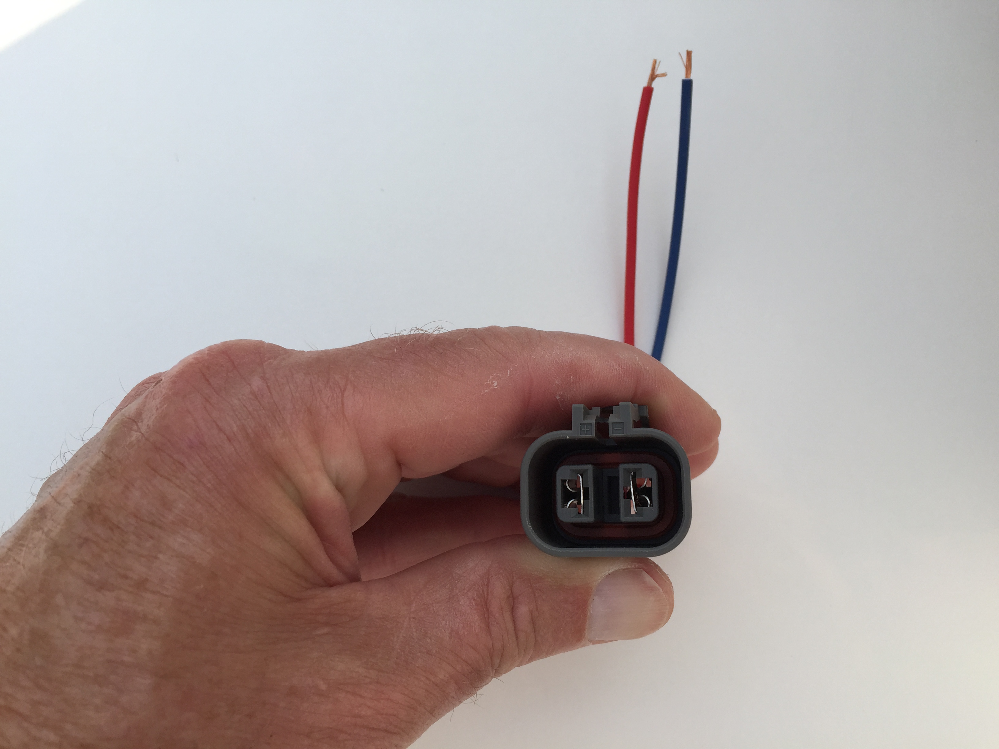
The blue wire from the tachometer is for the charging warning light and is spliced into a brown/yellow wire and routed through deutsch connector E1 to the alternator small spade connector.
Full instructions may be found at this link: Speedhut Speedo and Tach Instructions
Finally, the gps sensor wire is screwed into the fitting on the back of the speedo and routed behind the dash facia to the LH side. It is then routed between the door and the polished aluminum dash trim and is secured to the top of the dash with a magnetized plate.
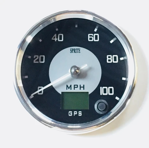
Speedhut Speedometer
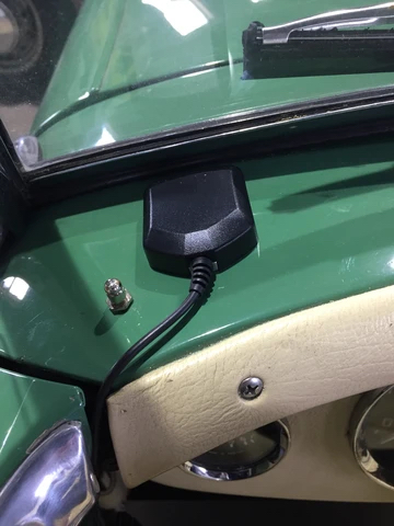
GPS Speedometer Sensor
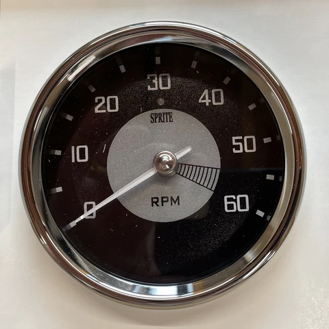
Speedhut tachometer
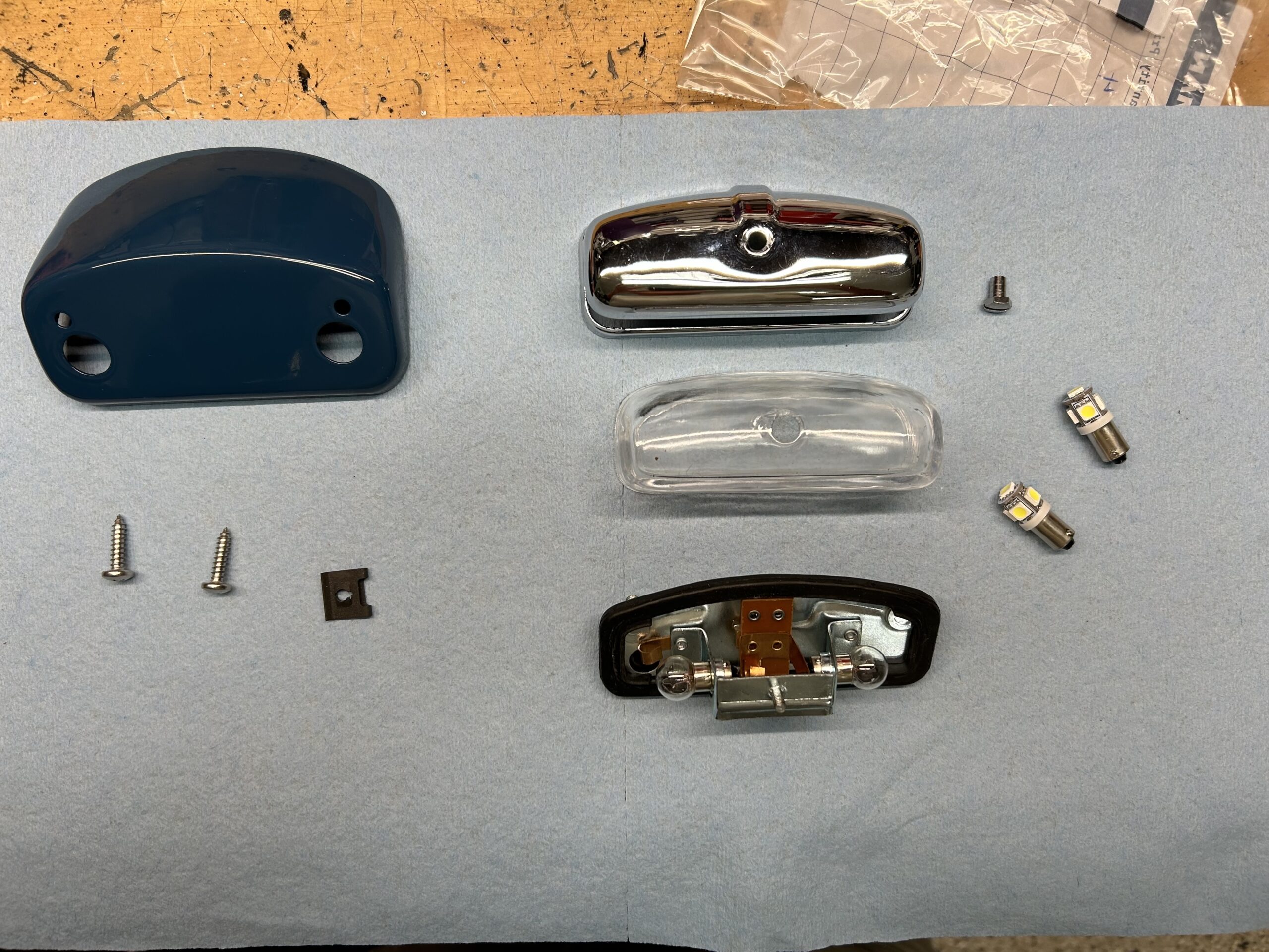
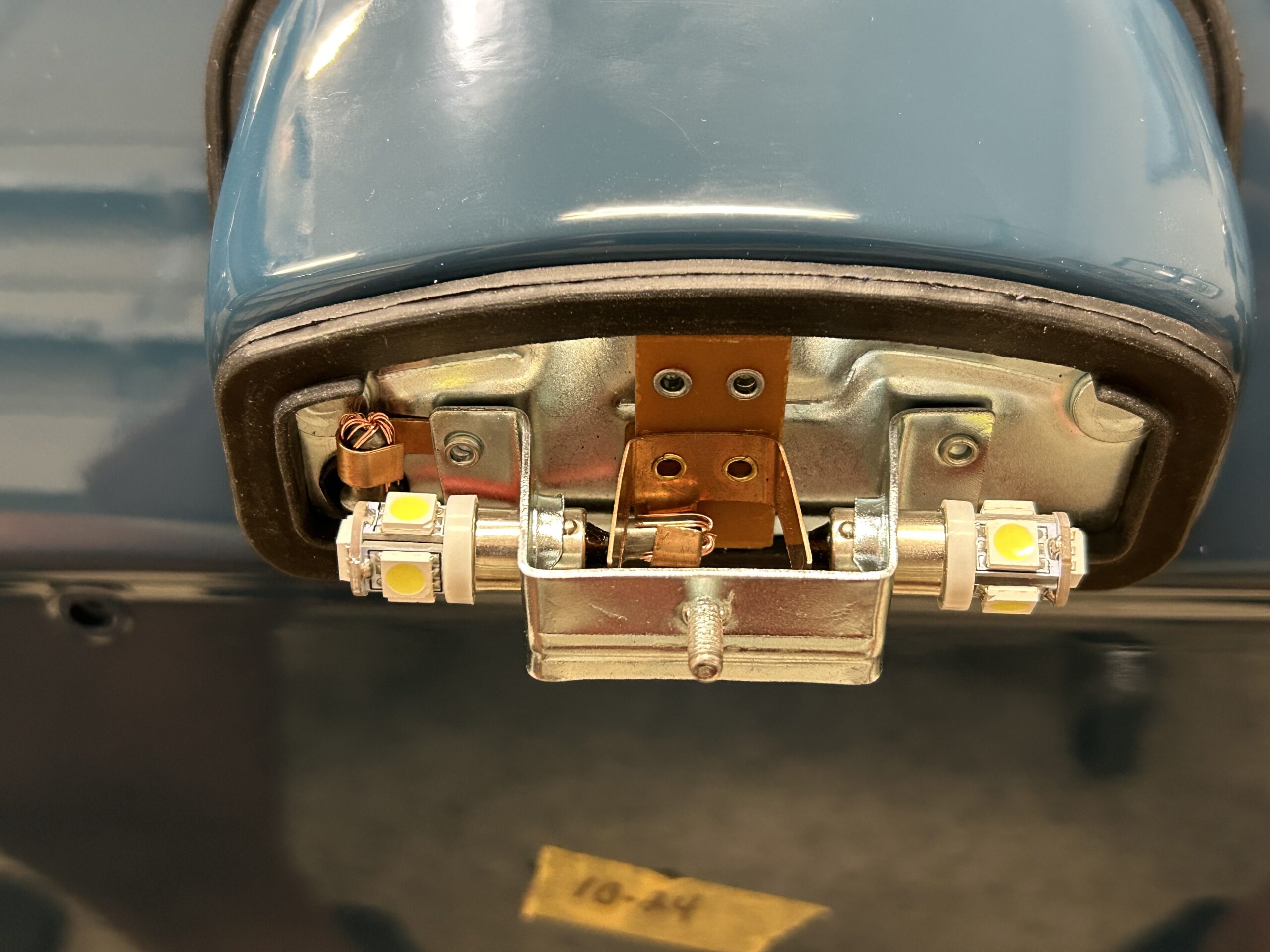
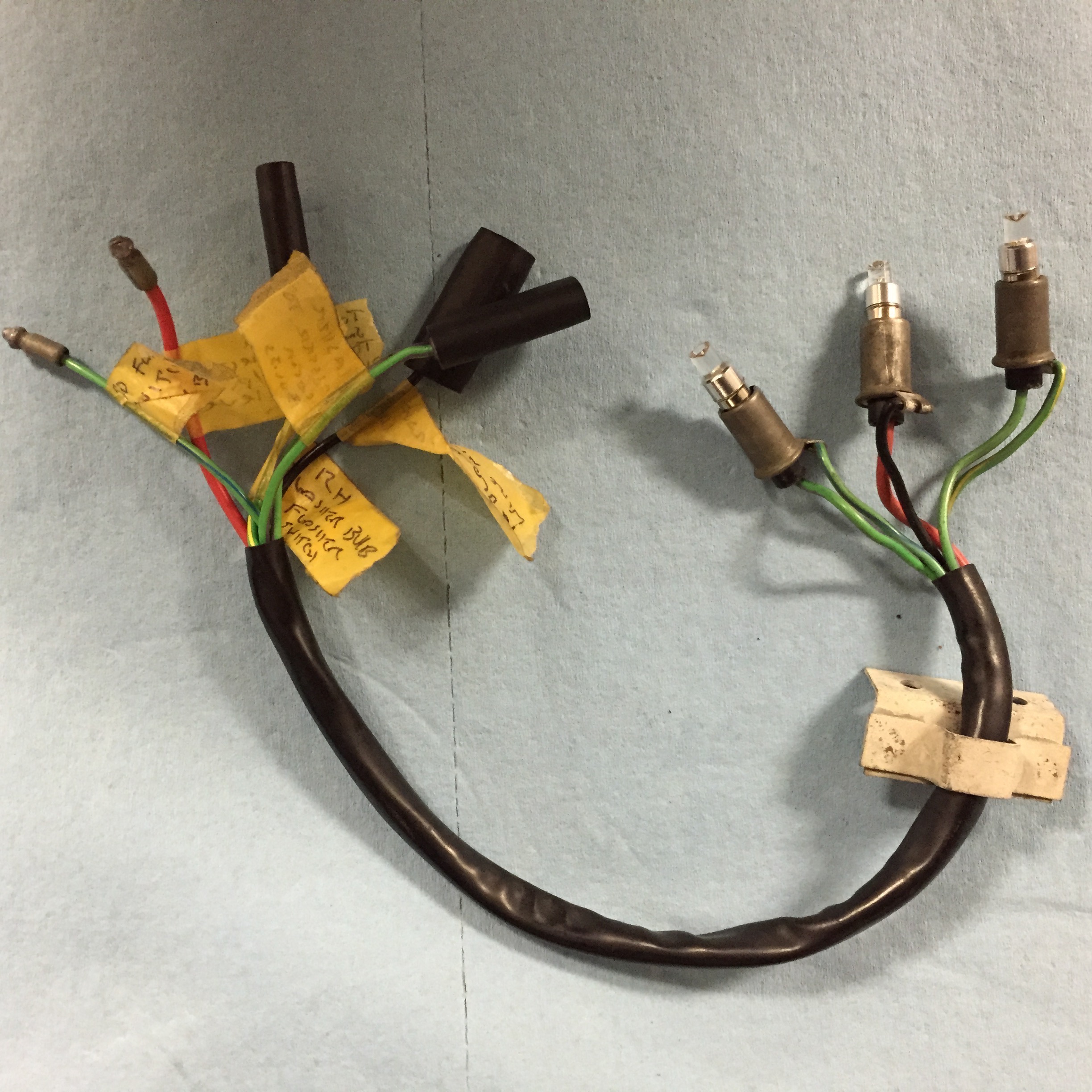
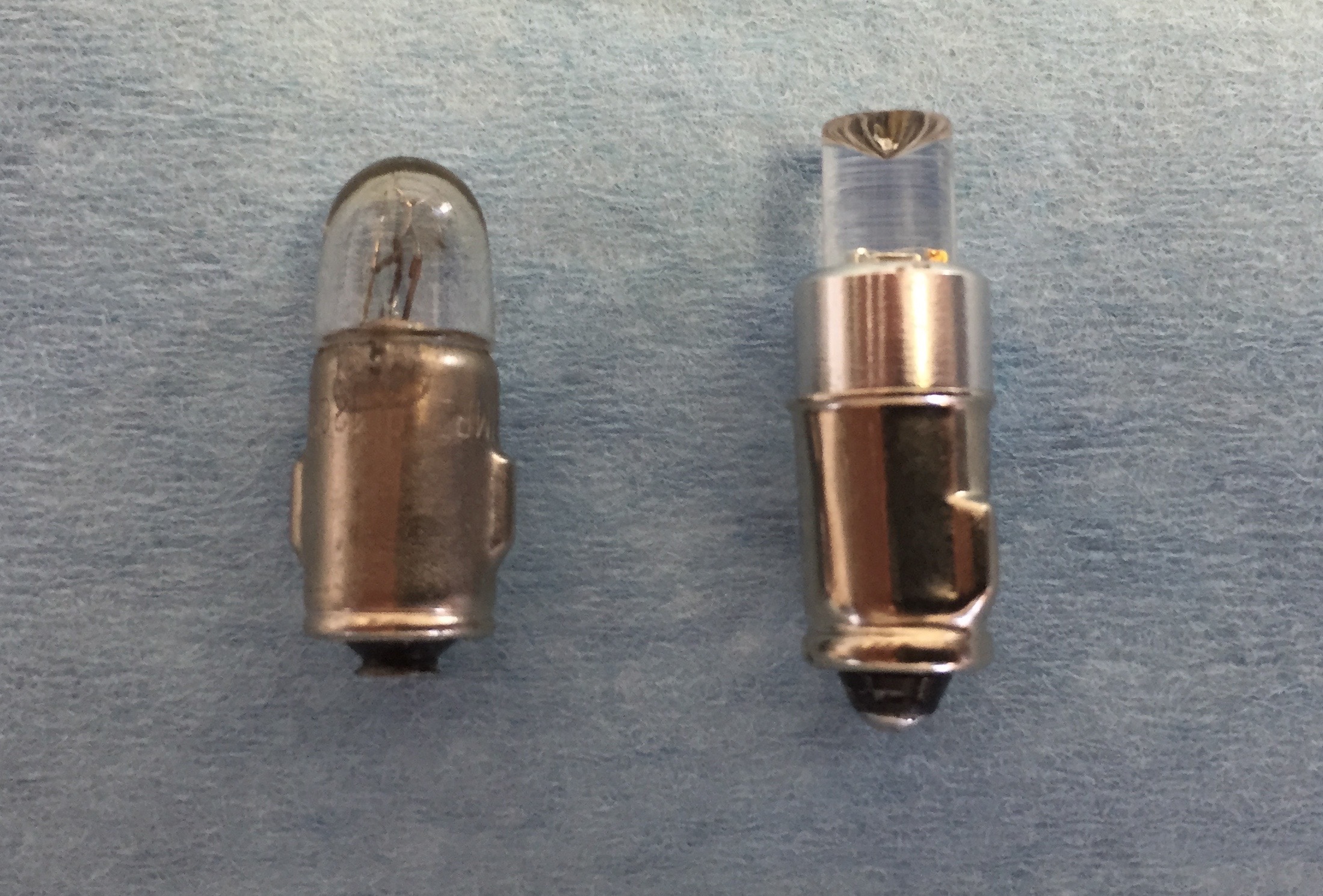
LED interior gauge lamps, flashers, side and tail lights and brake lights
All of the lights were converted from the original incandescent bulbs to LEDs sourced from Moss Motors.
LED Interior footwell and boot courtesy lights
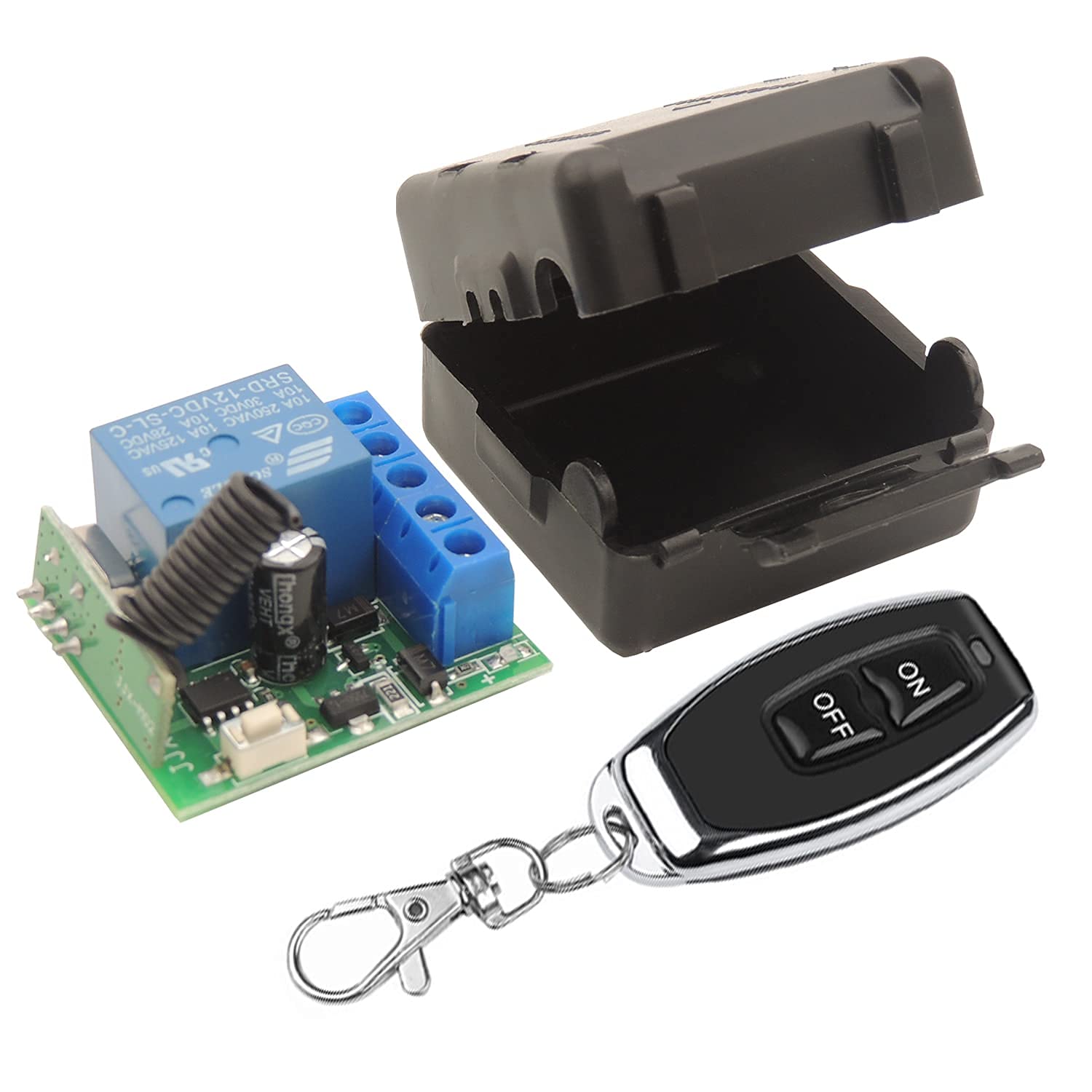
LED interior footwell, map and boot courtesy lights operate remotely by a key fob or manually with a toggle switch on the panel behind the dash. We ordered the RF Relay and key fob from Amazon. DieseRC 433Mhz Universal Wireless Remote Control Switch DC 12V 1CH RF Relay Receiver Module with 1 Transmitter, EV1527 Learning Code Remote Switch

RF Courtesy Light Controller
Visit the DieseRC Store. The relay may be set to operate with a delay, so in our case once the fob is clicked, the interior lights will remain on for forty seconds and then extinguish on their own with no action by the operator. We have also wired in a toggle switch so that the interior lights may be operated manually. The relay is mounted on the panel fabricated for the toggle switches immediately behind the dash.
The relay has five terminals:
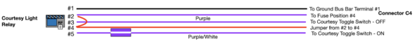
Courtesy Light RF Controller Wiring Schematic
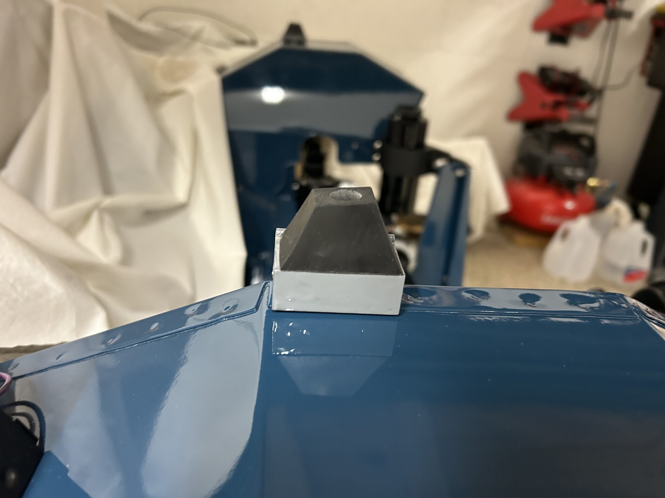
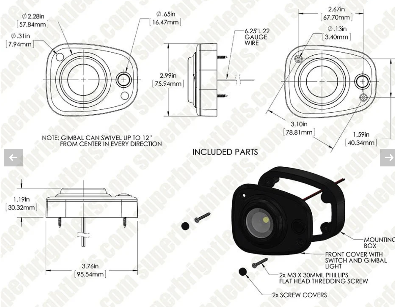
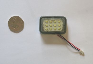
The boot has two aimable LED lights. Each one is mounted on the LH and RH rear interior quarter panels. These lights were sourced from SuperBright LEDS.
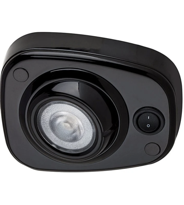
Boot LED Light
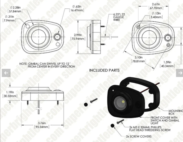
Boot Light Measurements
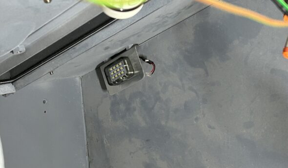
Wiring for the front lights will route directly from the designated toggle switch on the panel behind the dash to the lights. Wiring for the rear lights will be routed to the rear of the car through deutsch connector F1.
In the front footwells we also installed LED lights sourced from Better Car Lighting in the UK. We made some brackets to secure the lights and will use the bonnet prop stay captured nuts from the inside to mount them.
Footwell LED Lights
Footwell Lights and Brackets
Turn Indicator Warning Buzzer
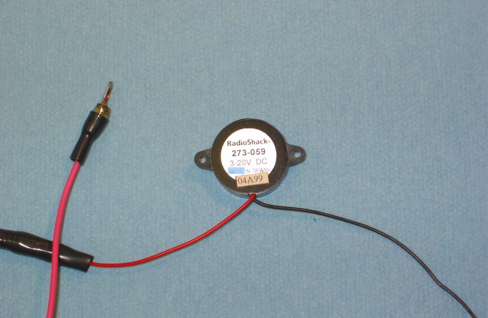
The turn indicator switch in the Bugeye is not self-canceling. While there is a warning lamp on the dash located between the speedometer and the tachometer, it is often not sufficiently bright to let the driver know to turn the switch to the off position. We installed a little buzzer sourced from Radio Shack to provide an audible alert when the flashers are turned on. The black wire from the buzzer is for ground and is connected to the LH Ground Bus Bar Terminal #2. The red wire is connected with a 4-way bullet connector to the flasher warning lamp.

Radio Shack Turn Indicator Warning Buzzer
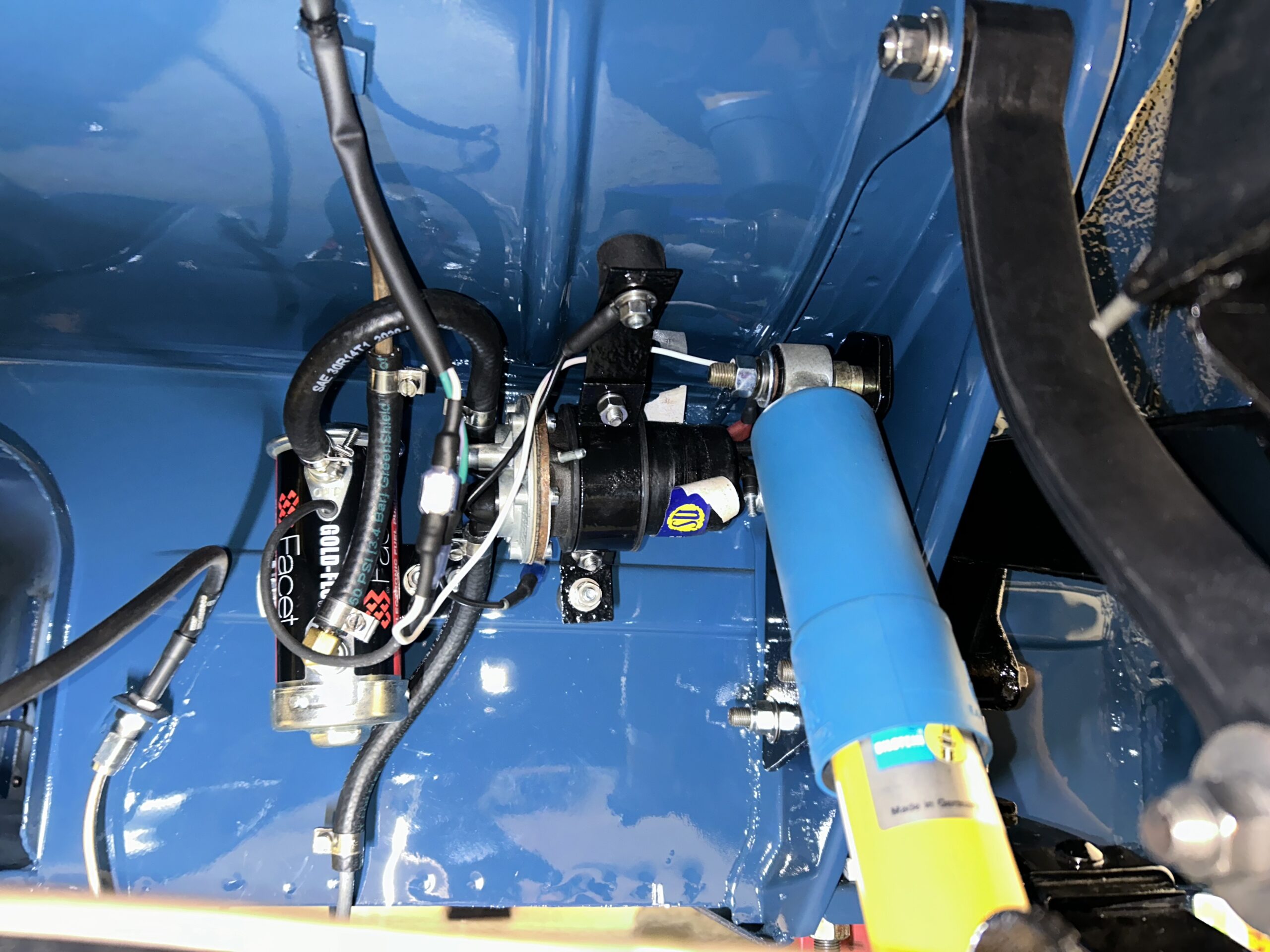
Dual Redundant Fuel Pumps
Although the newer solid state fuel pumps aren’t as likely to leave a driver standed when compared to the points pumps of the sixties, we still thought it a good idea to install two pumps in the Bugeye. Information about the pumps, their mounting and their plumbing is addressed in other posts about the fuel system, but notes about the electrical provisions for the pumps are appropriate here.
A toggle switch mounted in the panel behind the dash controls the fuel pumps. At center, neither pump is activated (a great anti-theft device); a throw upward activates the SU pump, and a throw downward activates the Master Pump. Each pump has its own black ground wire and they are mounted to the chassis near the pumps.
The pumps can be switched on the fly. The little chart below illustrates the wiring from the switch to the pumps.

Fuel Pumps Switch Wiring Schematic
The primary pump is the electronic SU pump. The pump is model number AUF214 and it was purchased from A.H. Spares in the U.K.
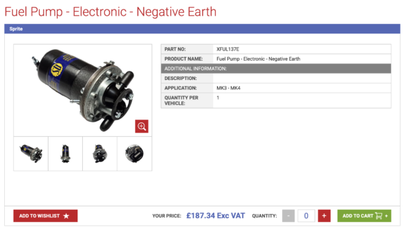
SU Electronic Fuel Pump from AH Spares
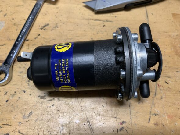
SU Pump
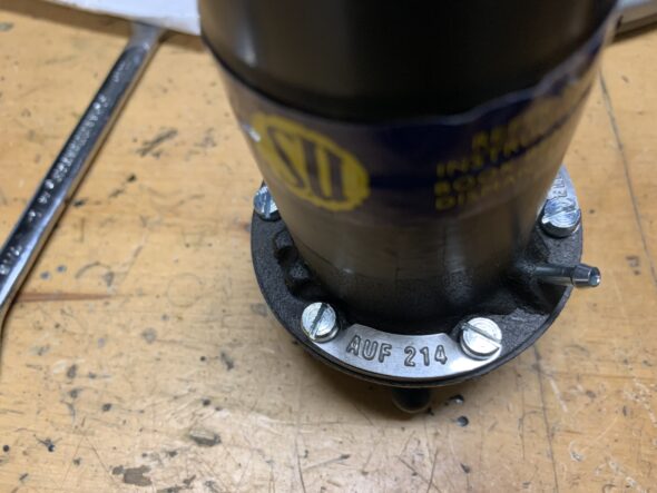
SU Pump Model Number
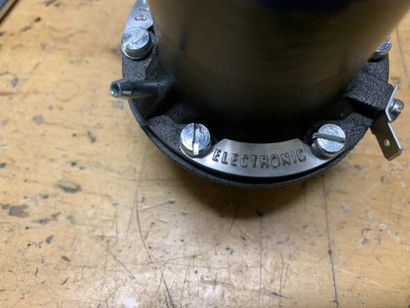
SU Pump Electronic
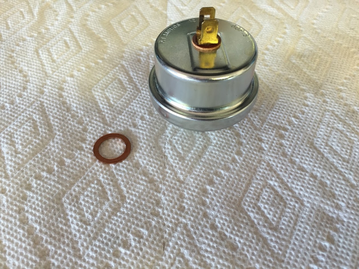
The back up pump was sourced from Pegasus Racing and it is a Facet Cylindrical pump rated at 2.75-4 psi.

Facet Pump From Pegasus Racing

Facet Low Pressure Pump
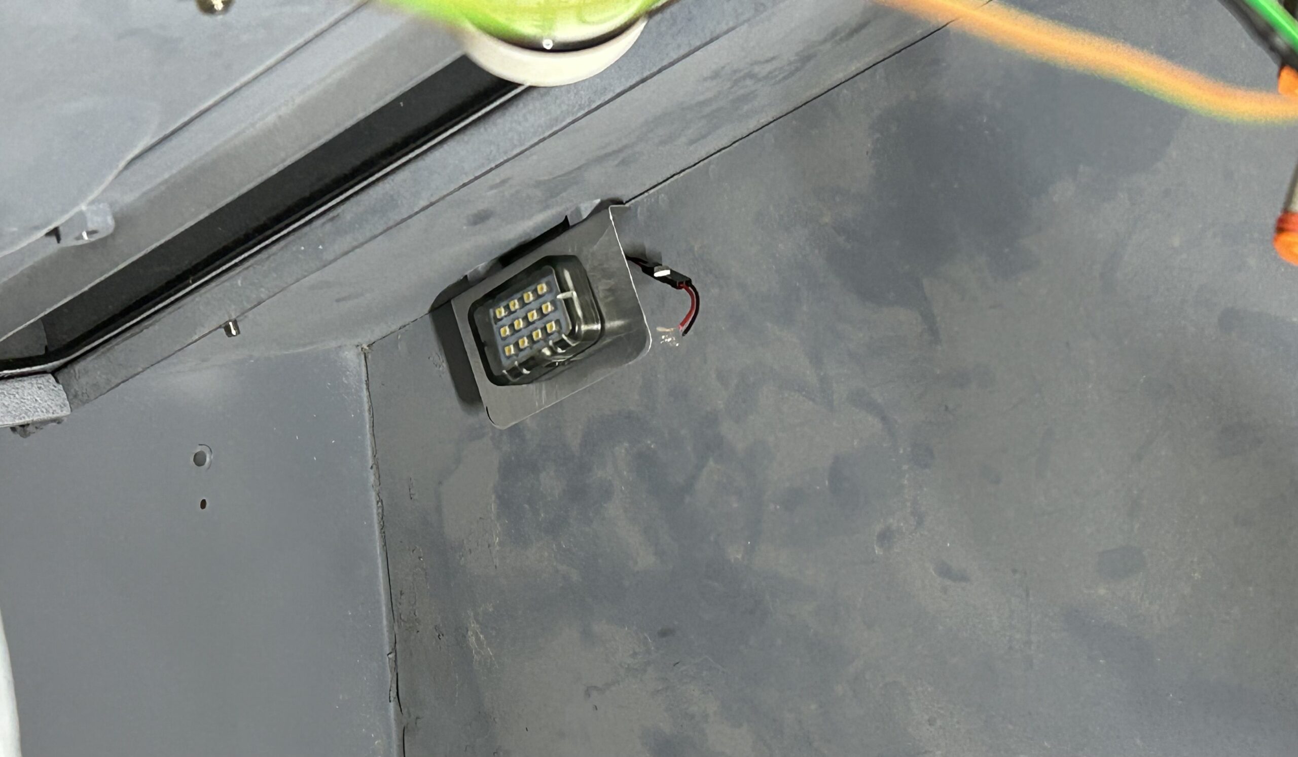
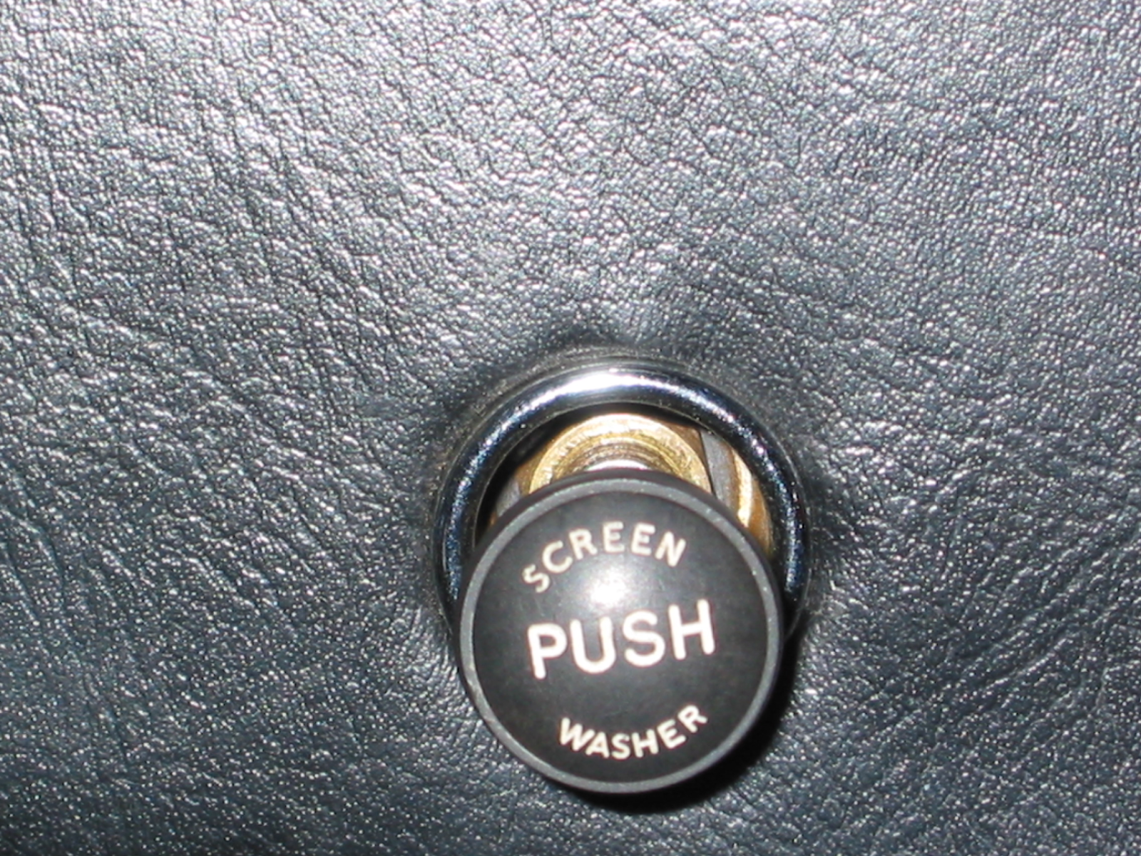
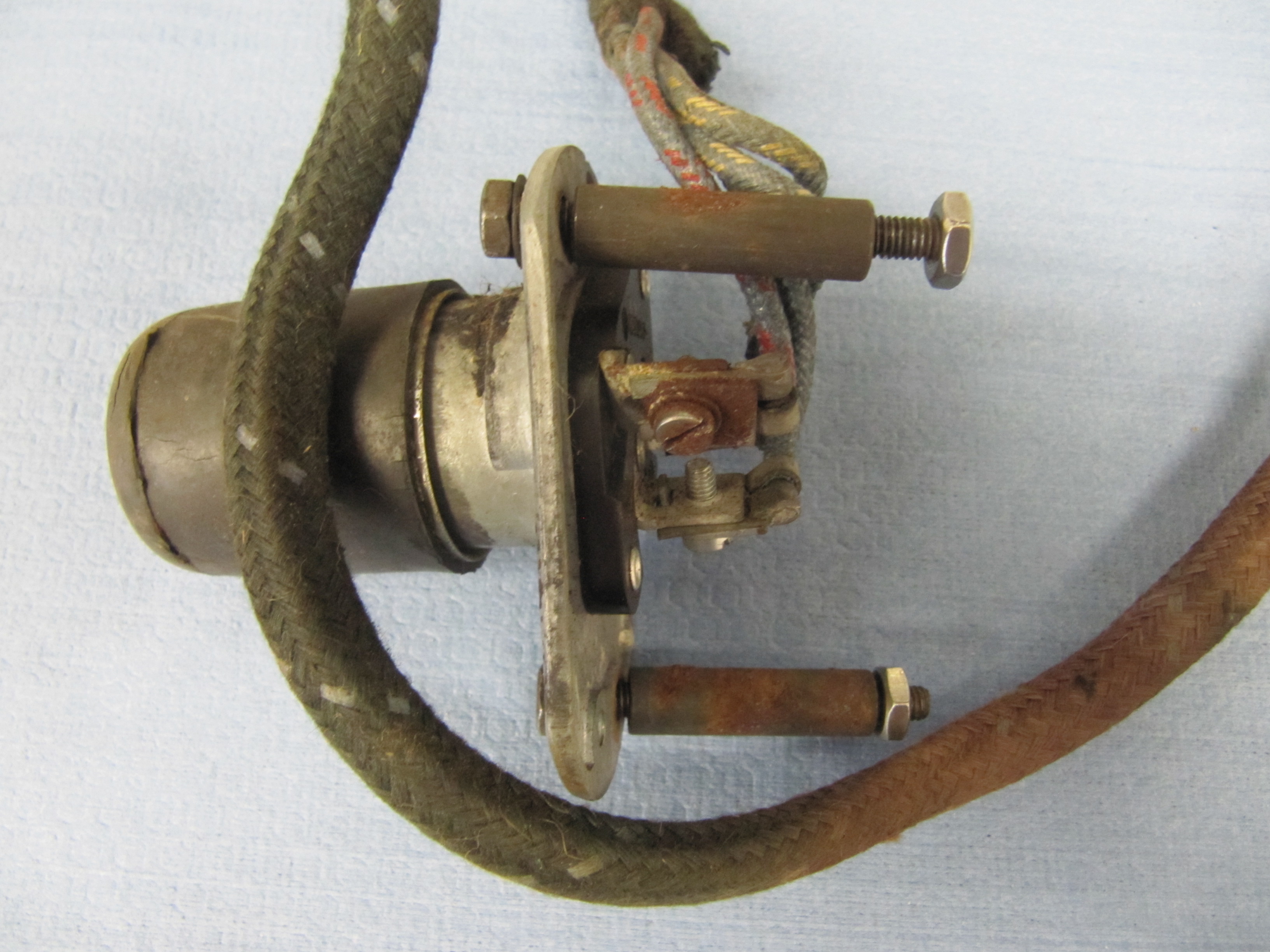
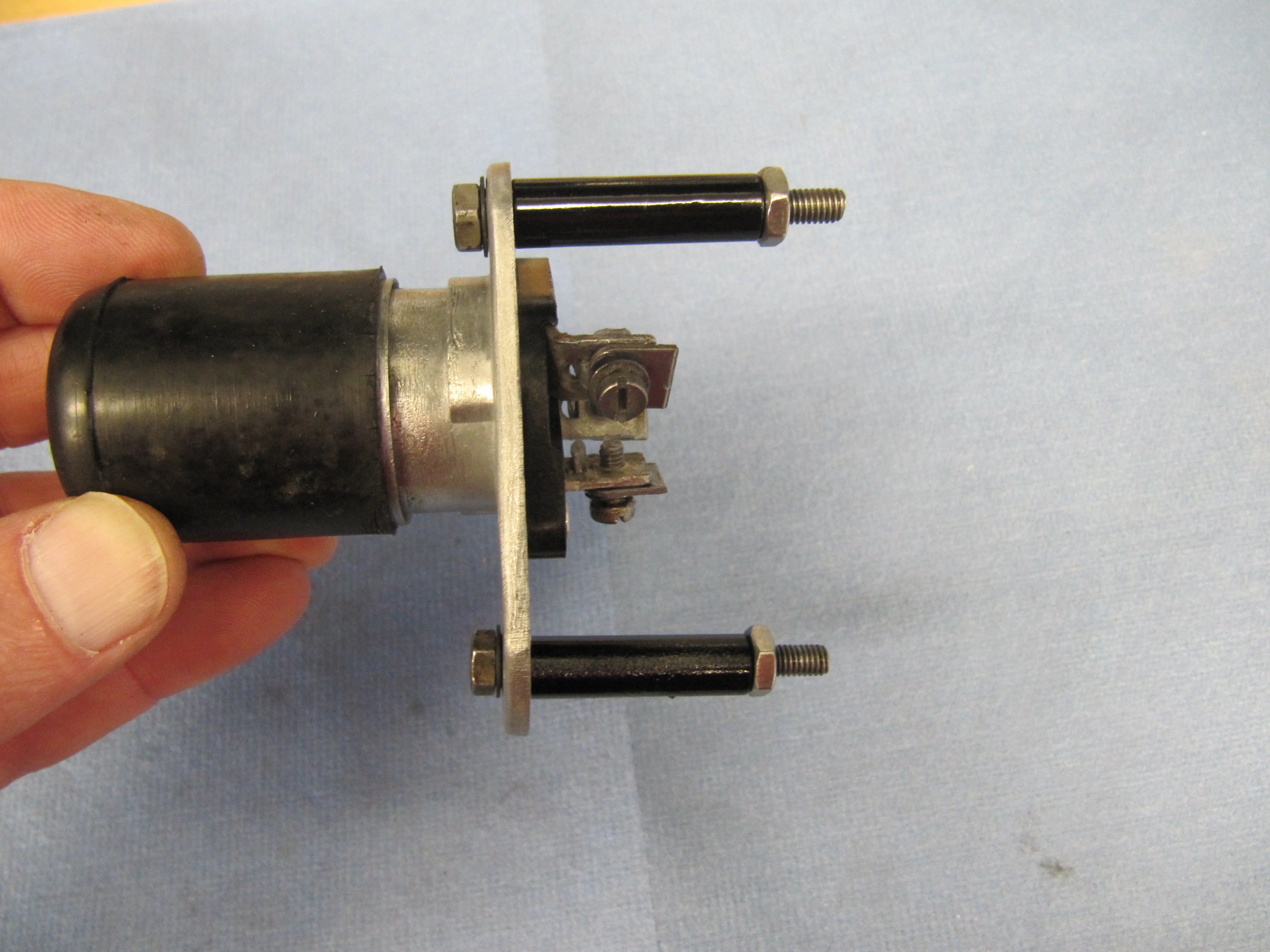
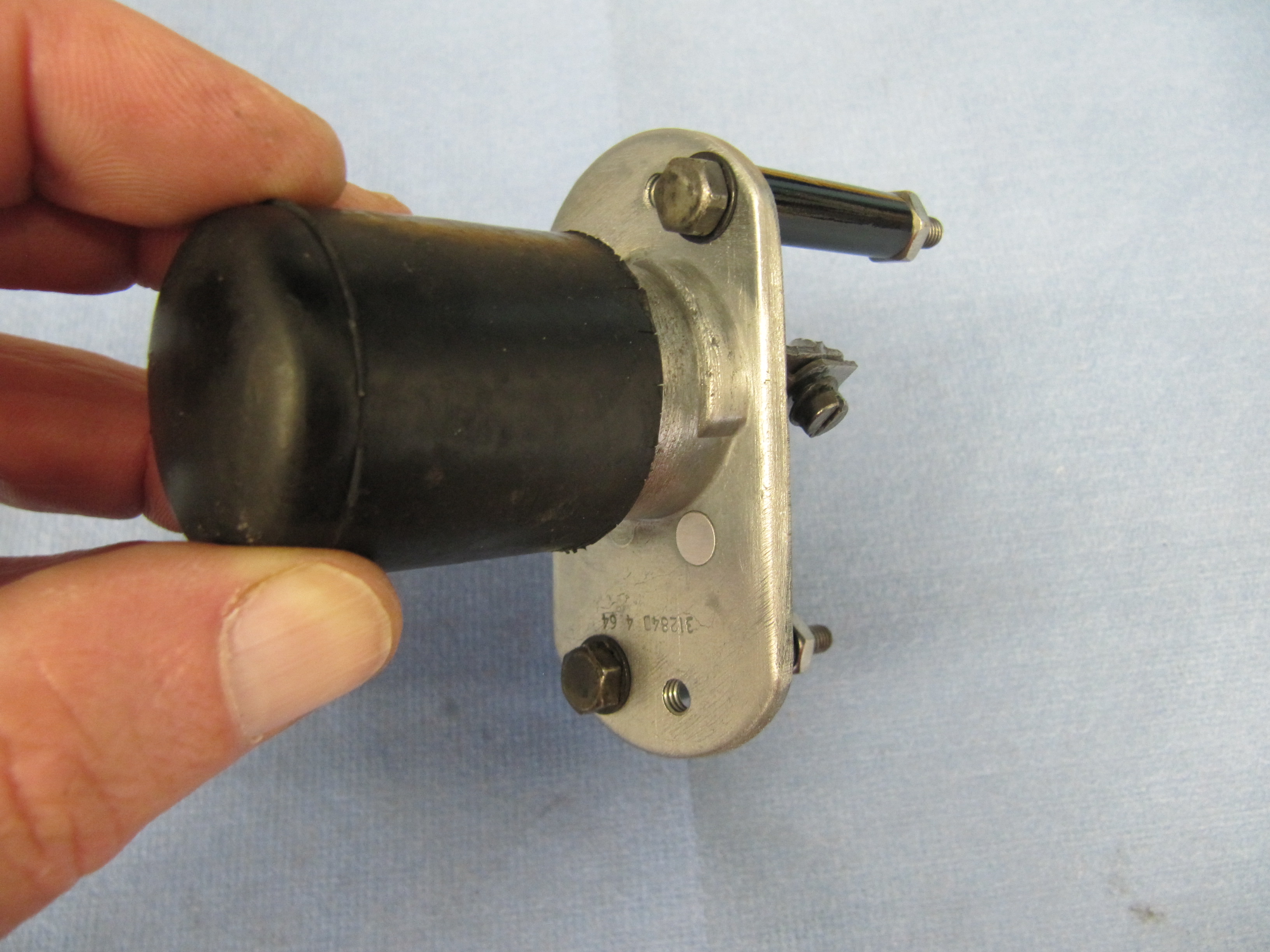
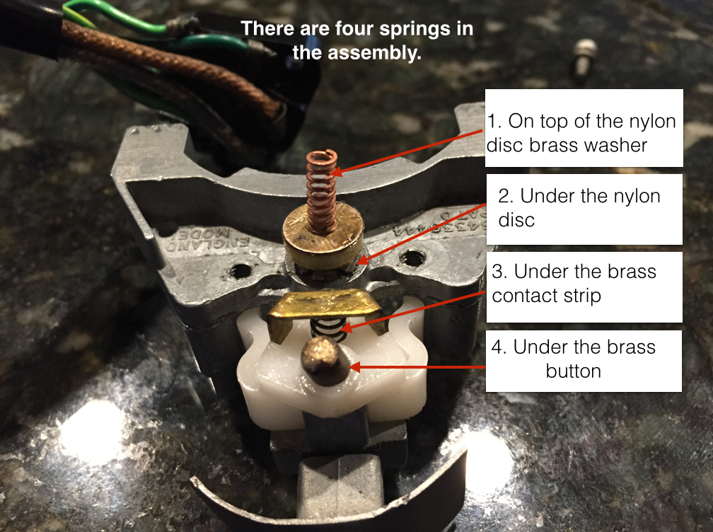
Modified Windscreen Washer Pump (plunger)
The Bugeye came equipped with a windscreen washer system that was activated by pushing a plunger mounted in the dash. The pressure created by pushing the plunger moved the cleaning fluid out to the windscreen. The process worked well enough, but when the Big Healey was restored we became aware of Stu Brennan, an owner of a Sunbeam Tiger, who had converted his hand activated pump windscreen washer to an electric washer. Stu’s idea was to put an electric momentary micro switch inside the aluminum pump canister thereby eliminating the need to install an additional switch somewhere. Since the washer in the Tiger is the same as the one in both the Big Healey and the Bugeye we decided to give it a try.
Two items needed to be purchased for the conversion. An electric pump typically used on later Sprites was ordered from Moss Motors. A Home Depot switch was purchased, Gardner-Bender, Push Button, GSW-22, SPST always-off.
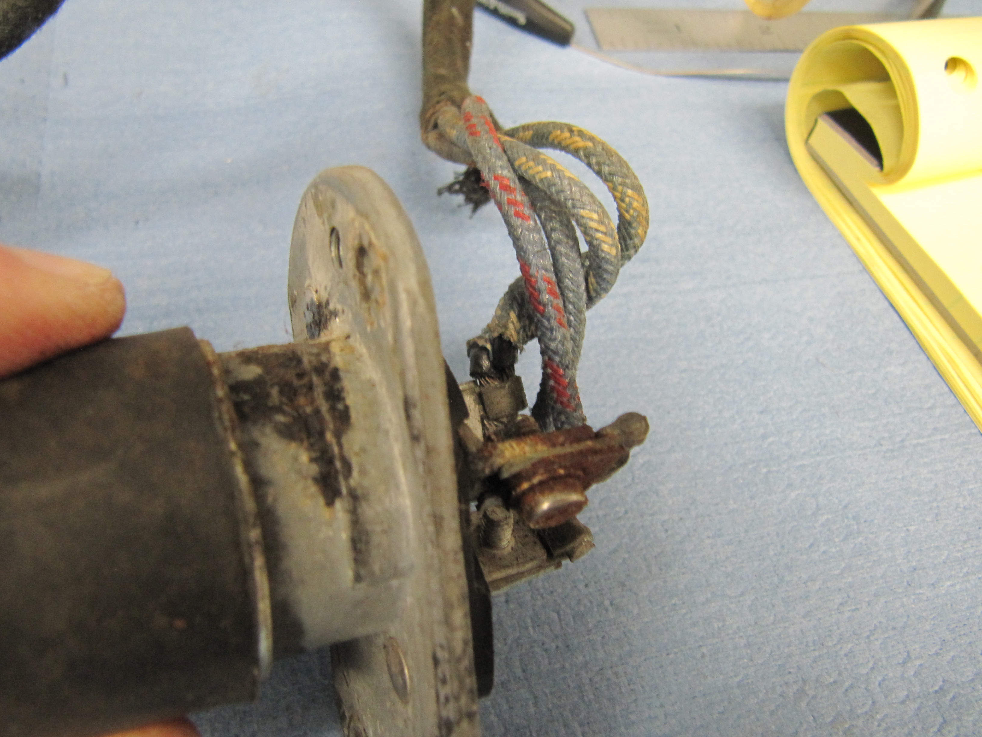
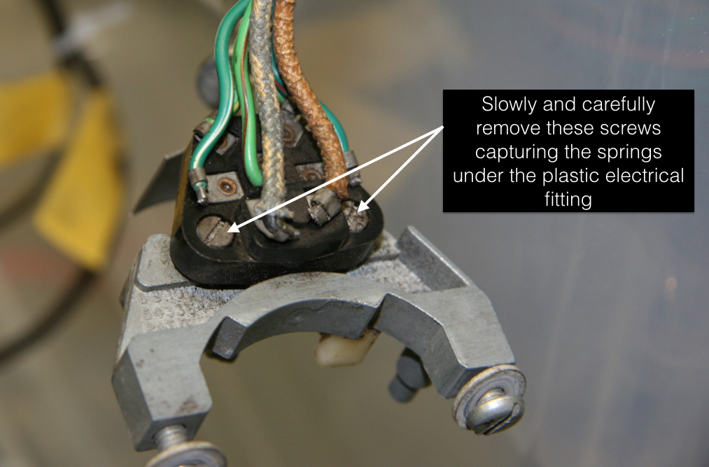
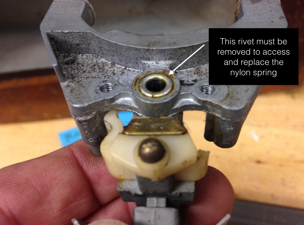
The old pump was easily disassembled by un-crimping the lip from around the plastic bottom. The metal is relatively soft, so it unfolds easily. The bottom and the old rubber bellows came right out, leaving only the plunger within the shell of the pump.

Modified Washer Pump
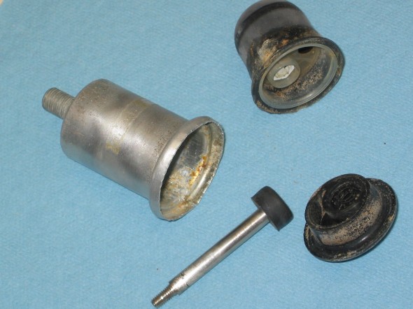
Washer Pump Parts
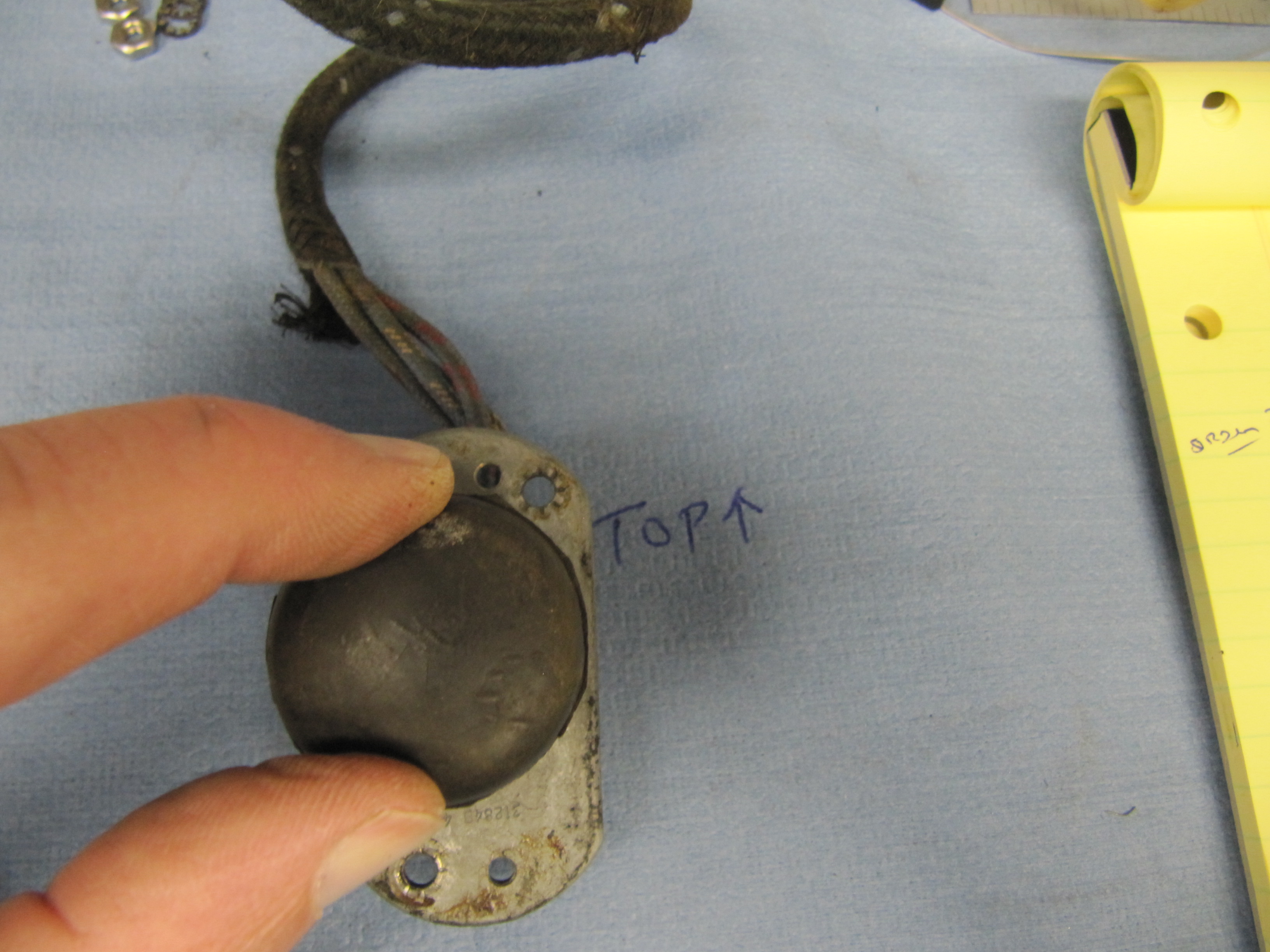
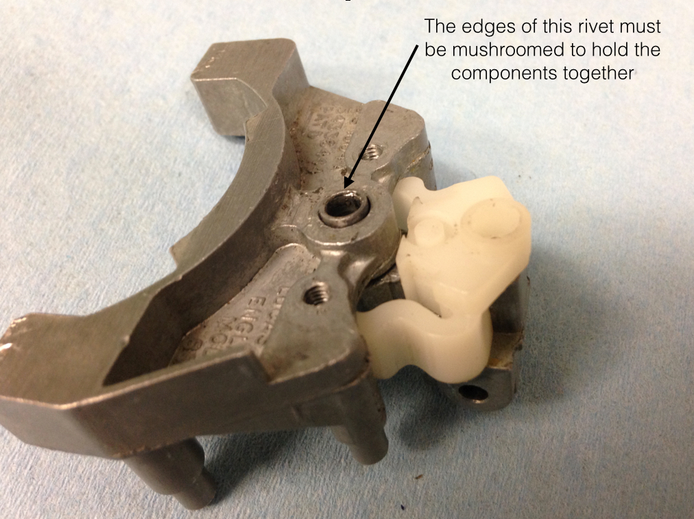
To provide enough depth for the switch in the canister a slot was cut in the plastic face plate. The slot also provided space for the switch wires to exit the canister. To provide stability for the switch in the canister and to use as a spacer a circle washer was cut of 1/4” wide plywood that fit tightly in the canister and placed it on the switch secured with double nuts.
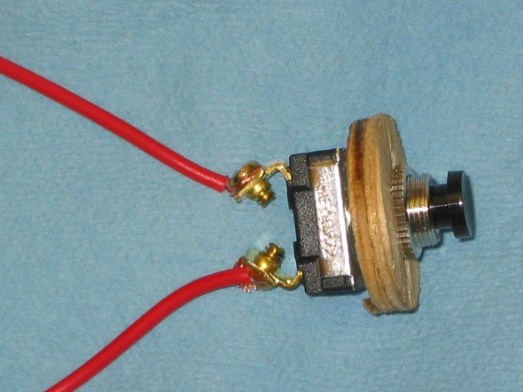
Washer Micro Switch
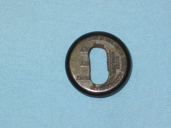
Modified Cap
The following diagram shows the wiring modifications made to adapt the new electric switch and pump to the electrical system:
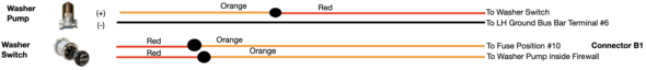
Washer Pump and SwitchmWiring Schematic
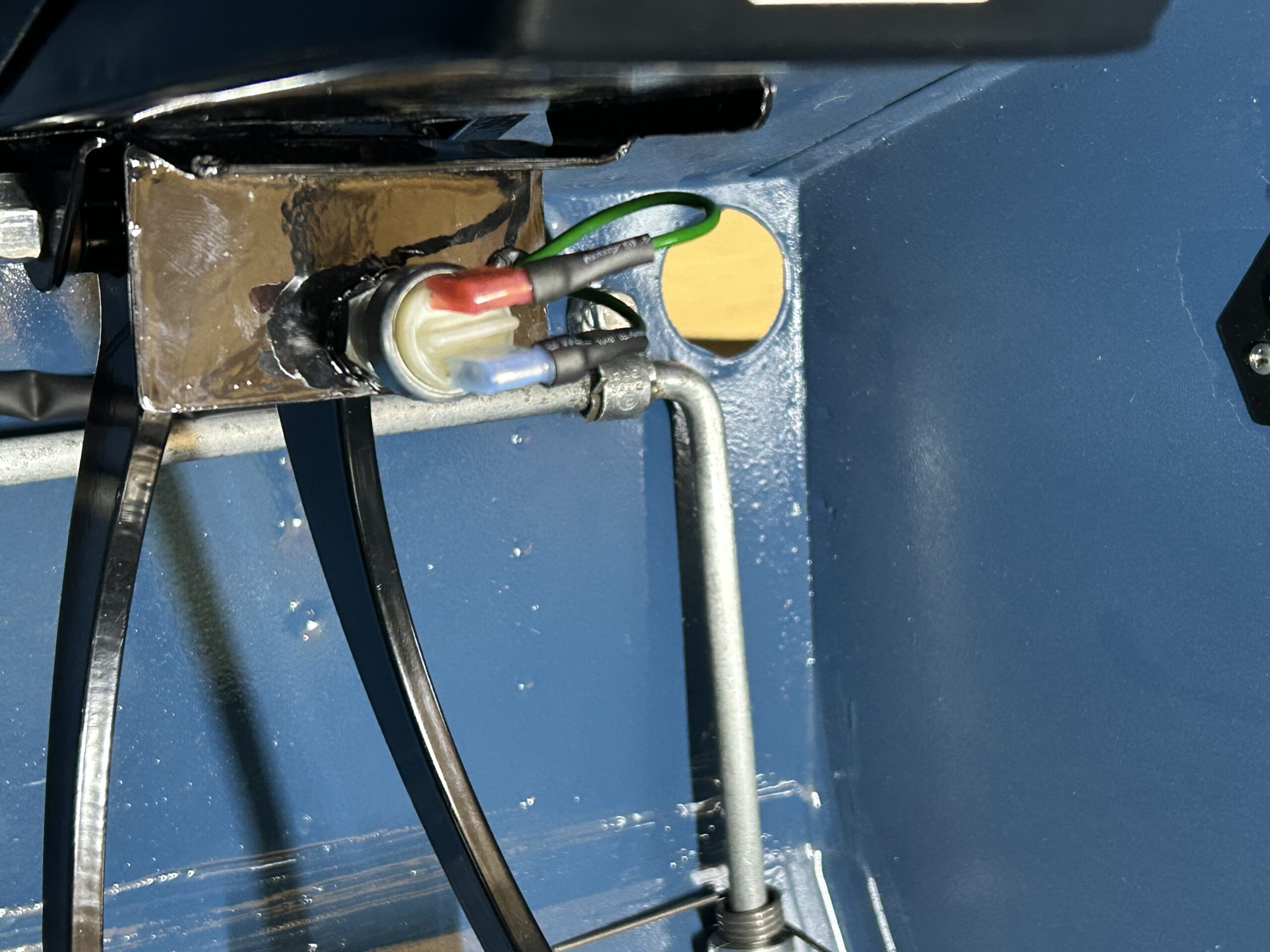
The modified switch has two red pigtail wires. Insulated spade connectors join the pigtails with the orange wire routed to the fuse box and the pump. The “negative“ side – black wire (–) of the pump is grounded to the LH Ground Bus Bar Terminal #1. The pump is mounted to a custom bracket connected to the housing for the bonnet hinge behind the dash.
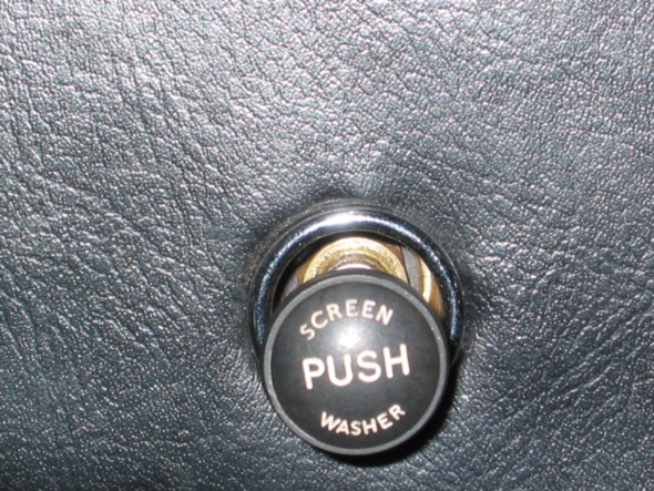
Washer Pump Push Button
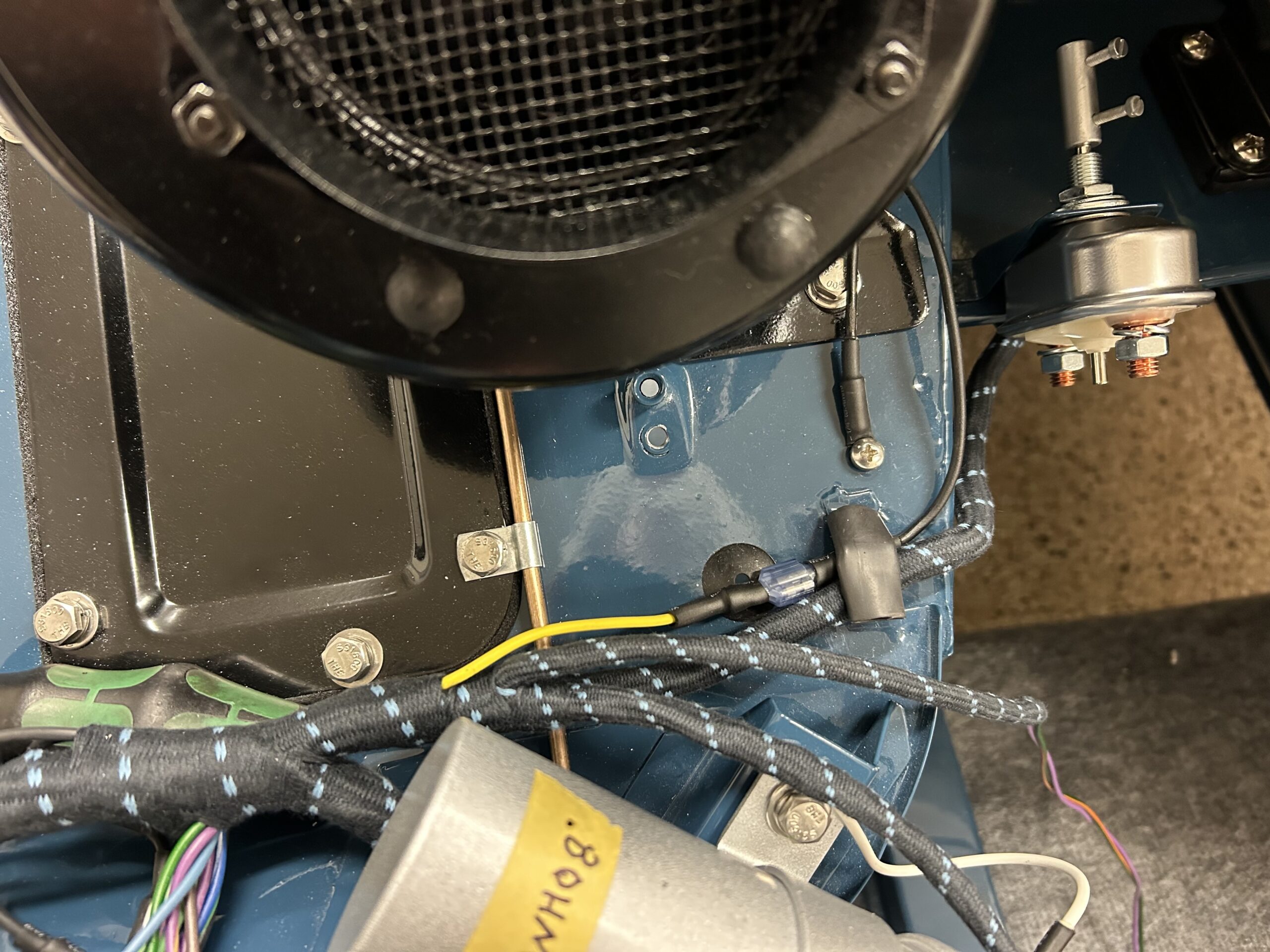
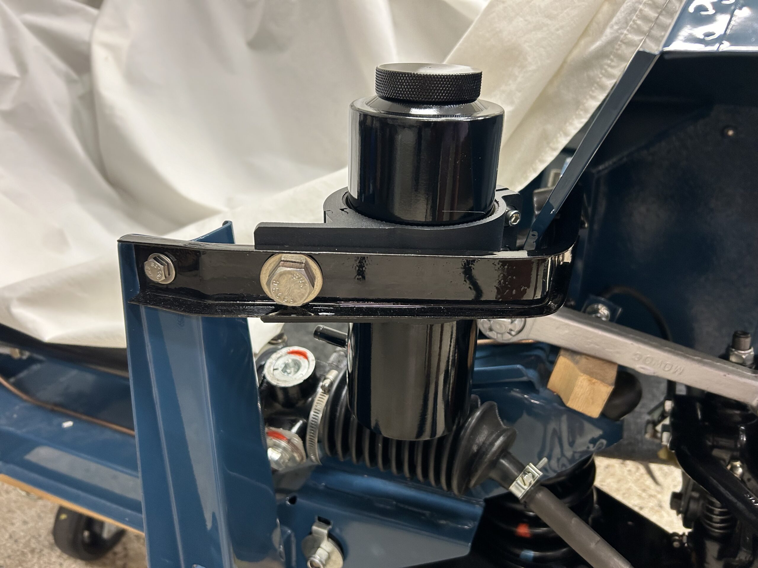
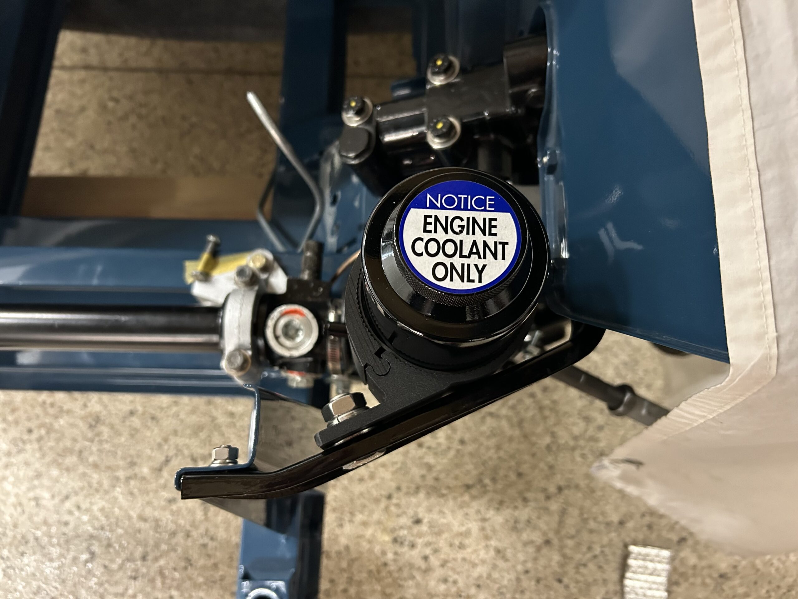
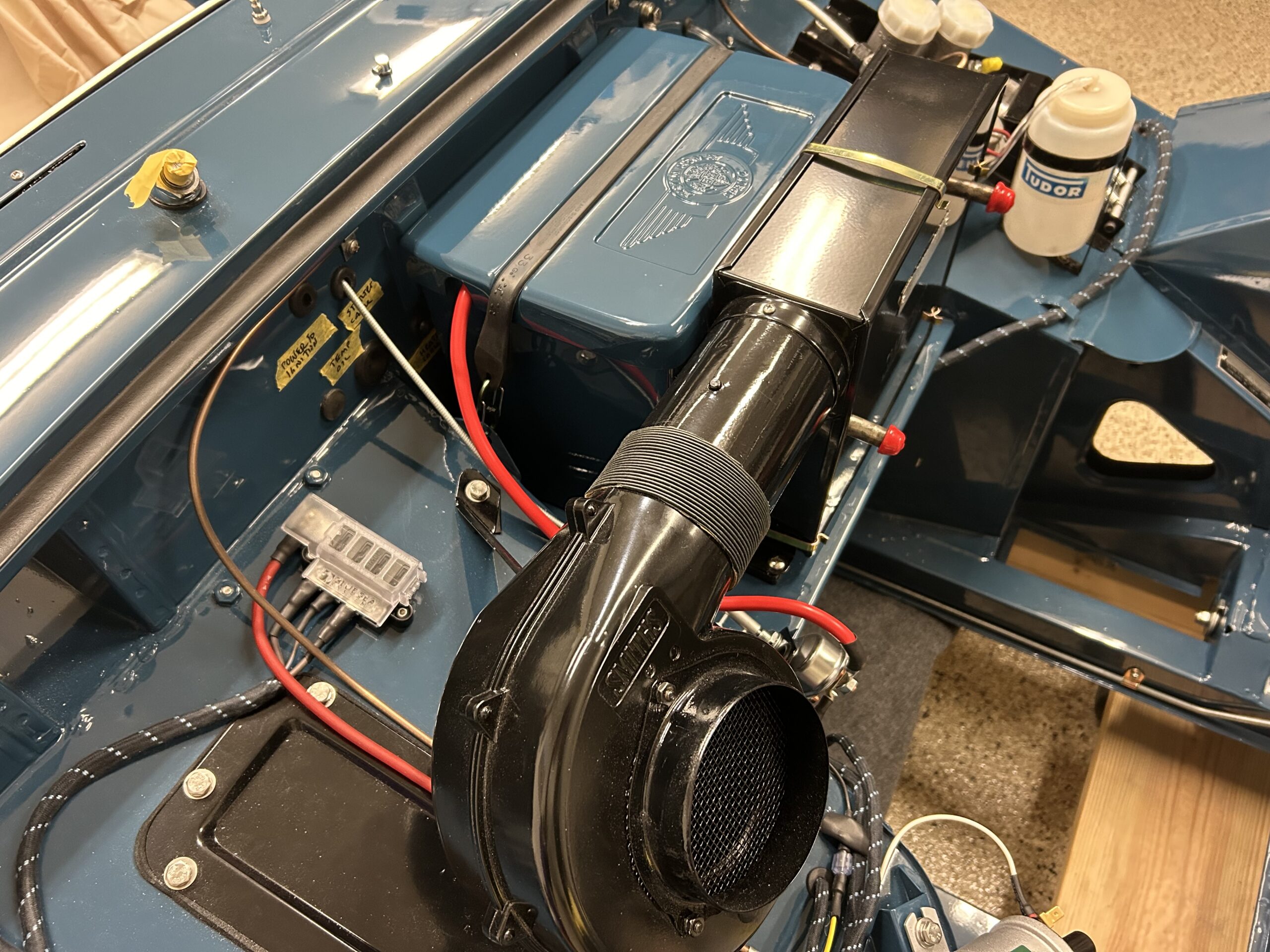
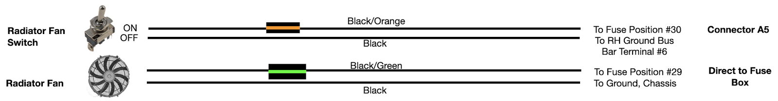
Radiator Electric Fan
We expect that the Bugeye with an engine in good shape and combined with a new aluminum radiator will run at comfortable coolant temperatures. However, in slow moving traffic conditions even an efficient Bugeye’s cooling system can be tested. To address those rare conditions, we decided to install a pusher electric fan. We elected to add a thermostatic control switch along with a toggle switch. Like our other toggle switches, this one is reachable but hidden from view in the custom panel behind the dash. The wiring diagram for the fan is below:
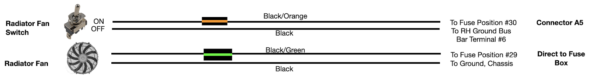
Washer Pump Wiring Schematic