In this video we build an engine starting stand. We decided to do this because we will be changing the pair of HS2 SU carbs currently on the car for a single SU HIF 44 carb. This obviously means that a change in the intake manifold is also required. The new manifold was sourced from Maniflow in England, but is not shown in the video because at the time the video was made the intake was being coated by Jet-Hot. We will also be switching from the 25D Lucas distributor to an electronic unit that is yet to arrive.
Another big motivator for going ahead with the engine stand is that the engine and gearbox are already out of the car, so easy-peasy!
There is also a leak from the timing chain cover that will need to be fixed and this way we will be able to run the engine to determine if we resolved the problem. If a second attempt is required, it will be much easier to fix while the engine is out of the car.
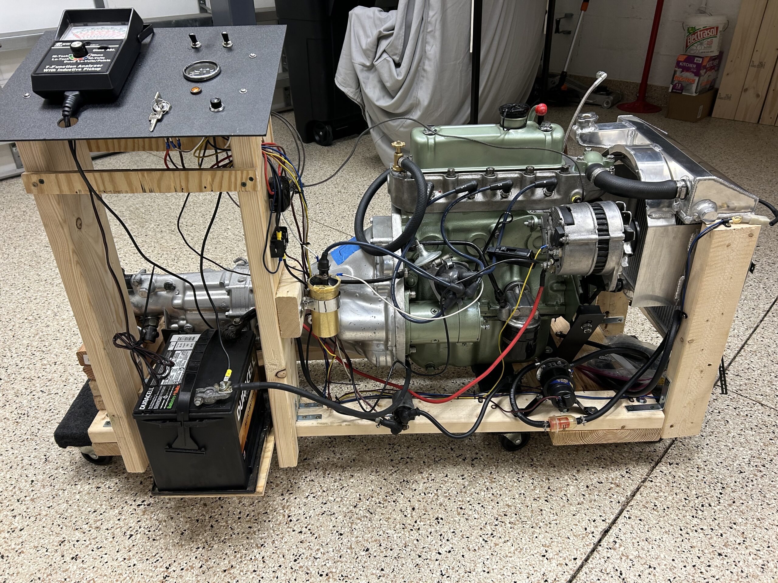
While final tuning needs to be done when the engine is under load, the engine run-in stand will allow us easy access for initial tuning. After constructing the stand from wood we then added the components necessary to start and run the engine. The ignition switch, starter button and starter solenoid from a Big Healey were utilized in the build. An analog engine analyzer was incorporated to primarily provide a tachometer function when testing and tuning the engine. A pair of Harbor Freight moving dollies were used to enable wheeling the new stand around the garage. The exhaust including the muffler will be attached when it is time to start the completed engine.
This view of the stand shows the installation of the radiator and an electric cooling fan. For test purposes the engine-driven mechanical fan is removed. Since the heater is not part of this system, a 1/2″ section of heater hose is used to connect the water valve and the return pipe.
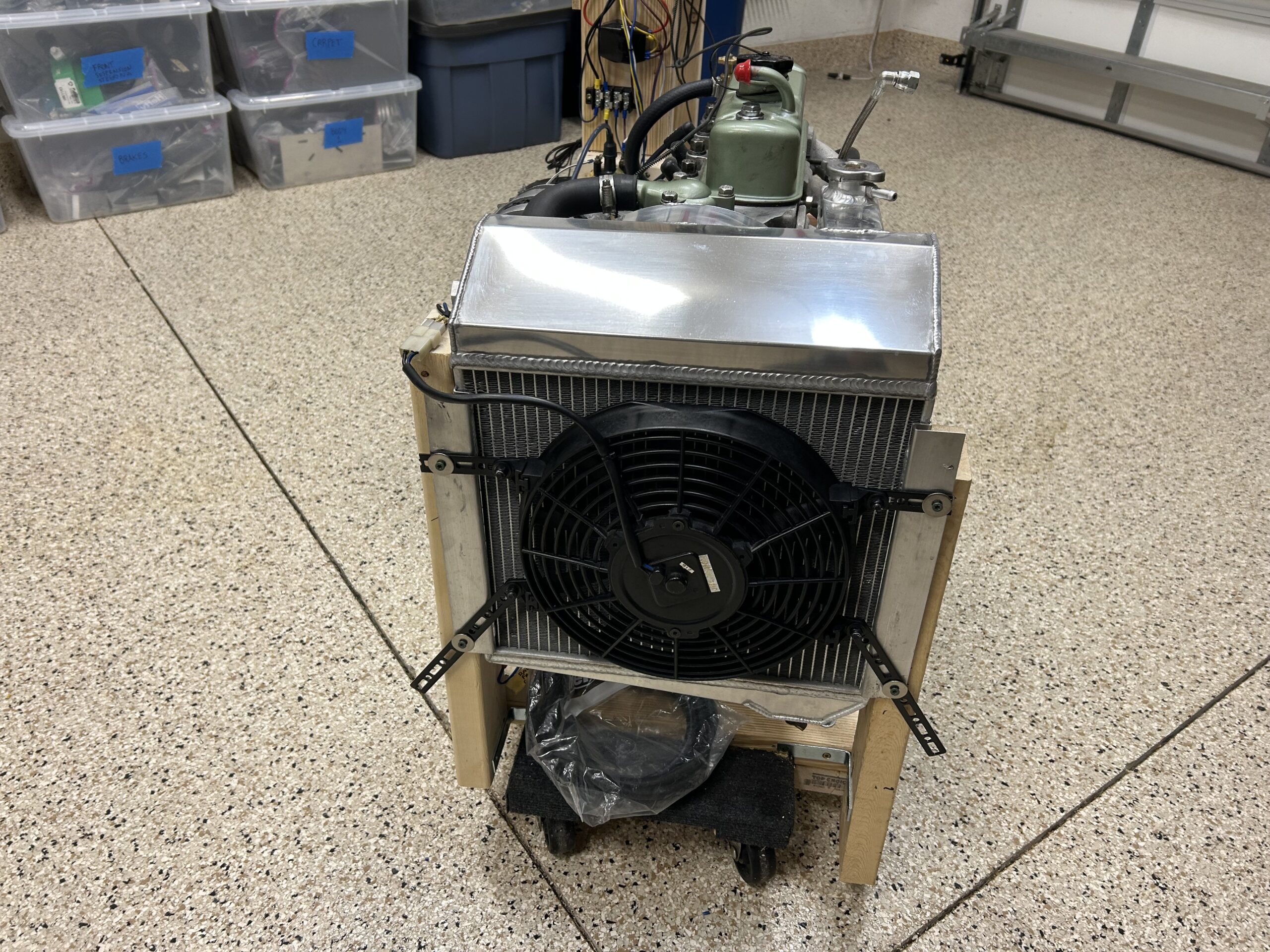
Radiator and fan on engine stand
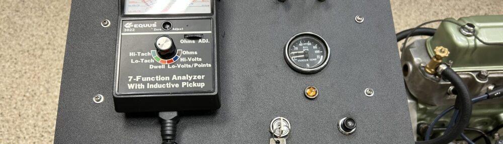
This view shows “Mission Control.” The panel includes the engine analyzer/tachometer, the keyed ignition switch, starter switch, charging warning light, the water temperature and oil pressure gauge, and toggle switches for the radiator electric fan and the electric fuel pump.
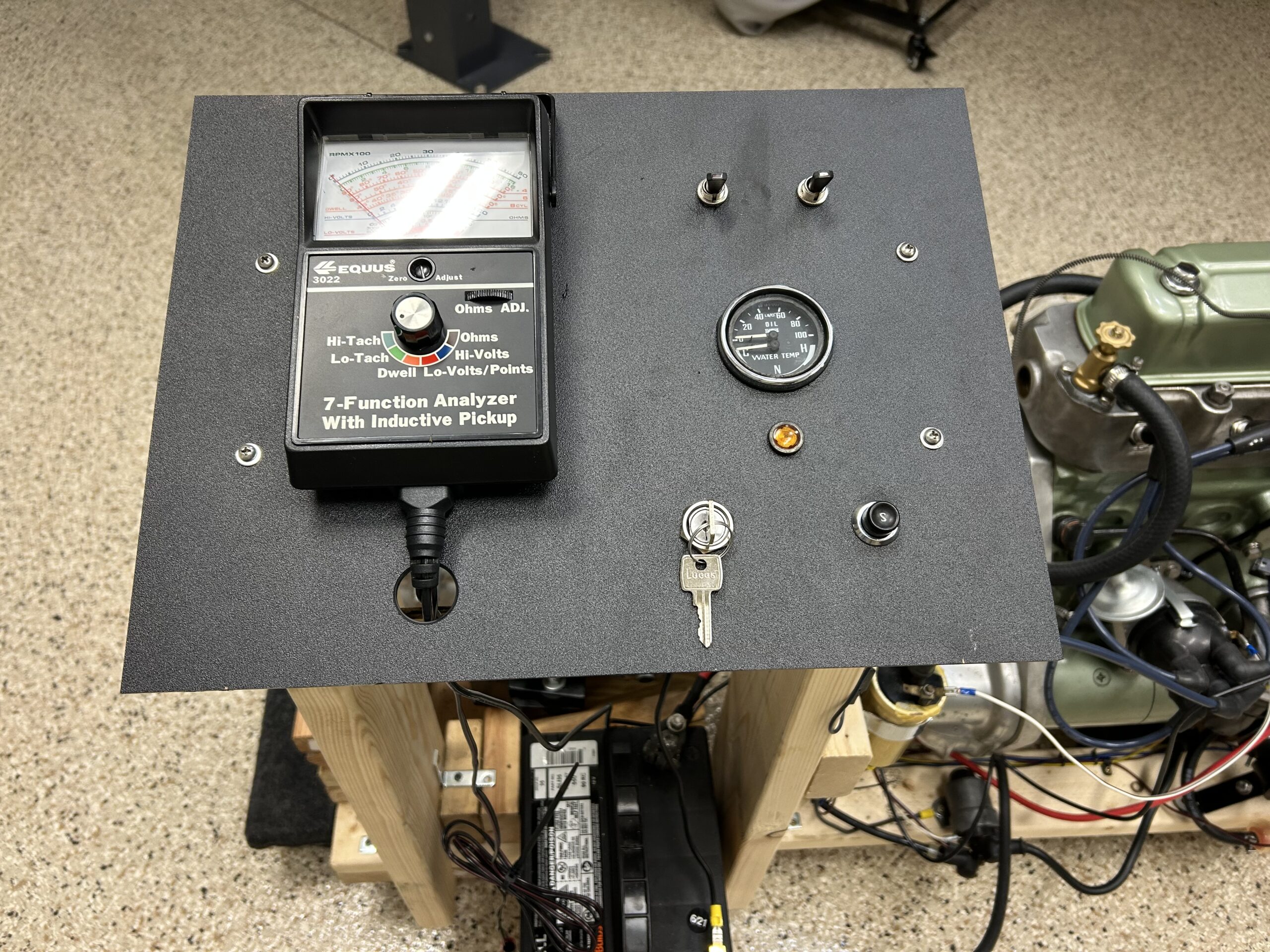
Mission Control
In this view most of the components required to start the engine are visible: the battery, starter solenoid, fuse panel, ground bus bar, fuel pump and hose, ignition coil and distributor are all visible.
Engine Starting Components
The intake manifold, the new carburetor, and the exhaust still need to be added.
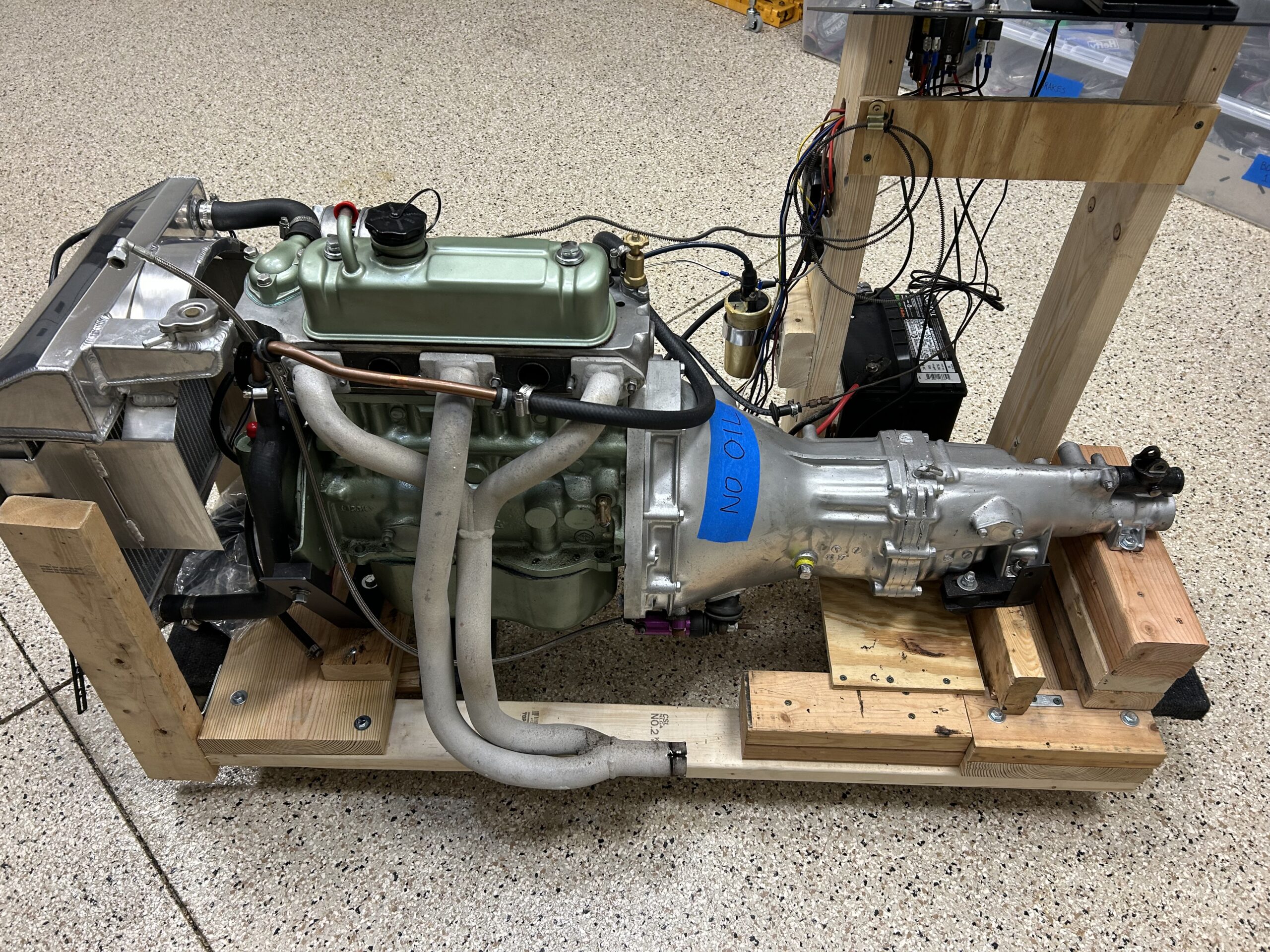
Intake, Carb and Exhaust to be Added
This is our wiring schematic. All of the electrical circuits have been checked but anyone interested in building a similar plan should develop their own wiring plan. This worked for us, but may not work for you.
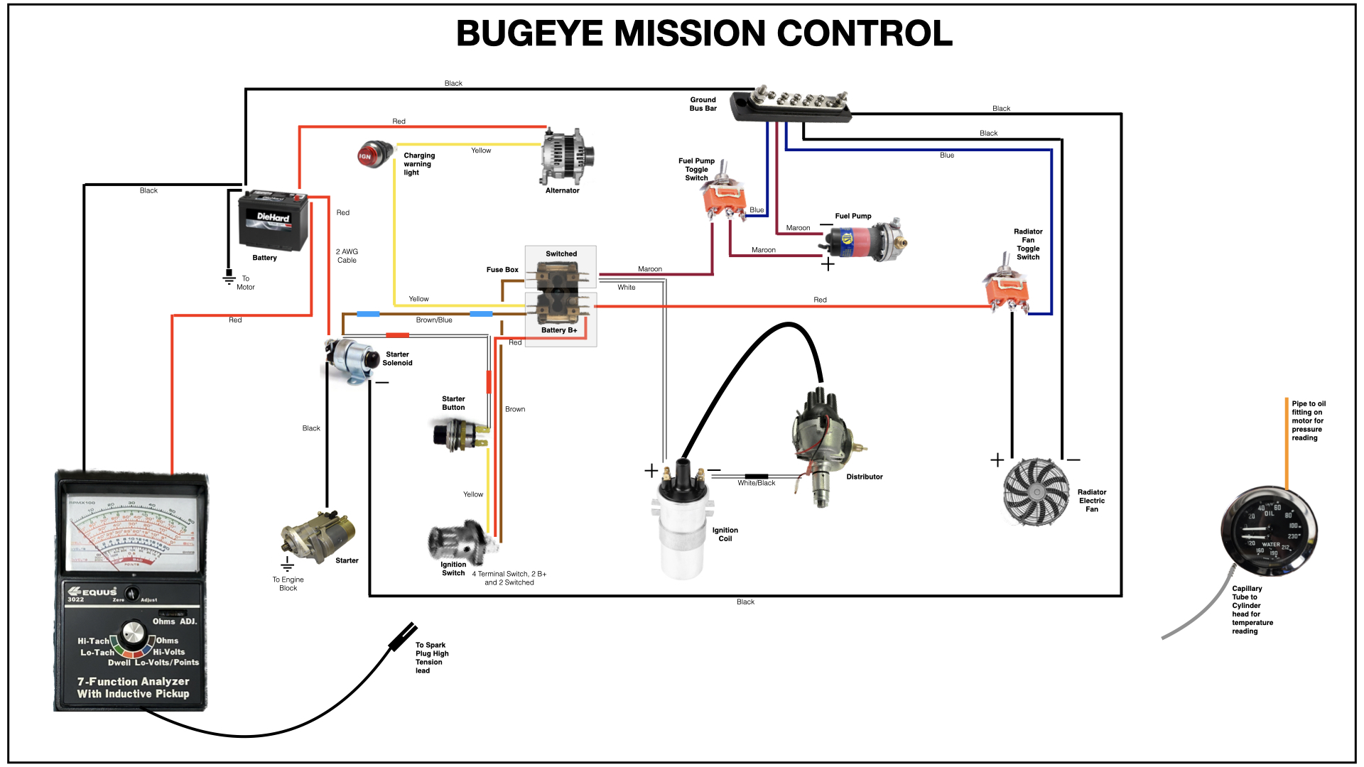
Mission Control
Bugeye Restoration Video Episode Forty-six provides a visual summary of the engine stand construction: https://vimeo.com/864520391/1954686c70?ts=0&share=copy