
After a few gorgeous days on at the Chesapeake Bay, I am back at finishing the boot. I glued down the left Armacord panel that covers the trough and extends to the rear shroud. I am going to wait on the right one, under the battery, until the shroud is mounted. The new aluminum fuel tank was then put in place. The pipe connection to the fuel line was made at the rear of the tank, and the two securing straps were bolted down.
At the suggestion of other British Car Forum members, I added a ground wire from the fuel sending unit to the frame and I connected the power wire to the sending unit terminal.
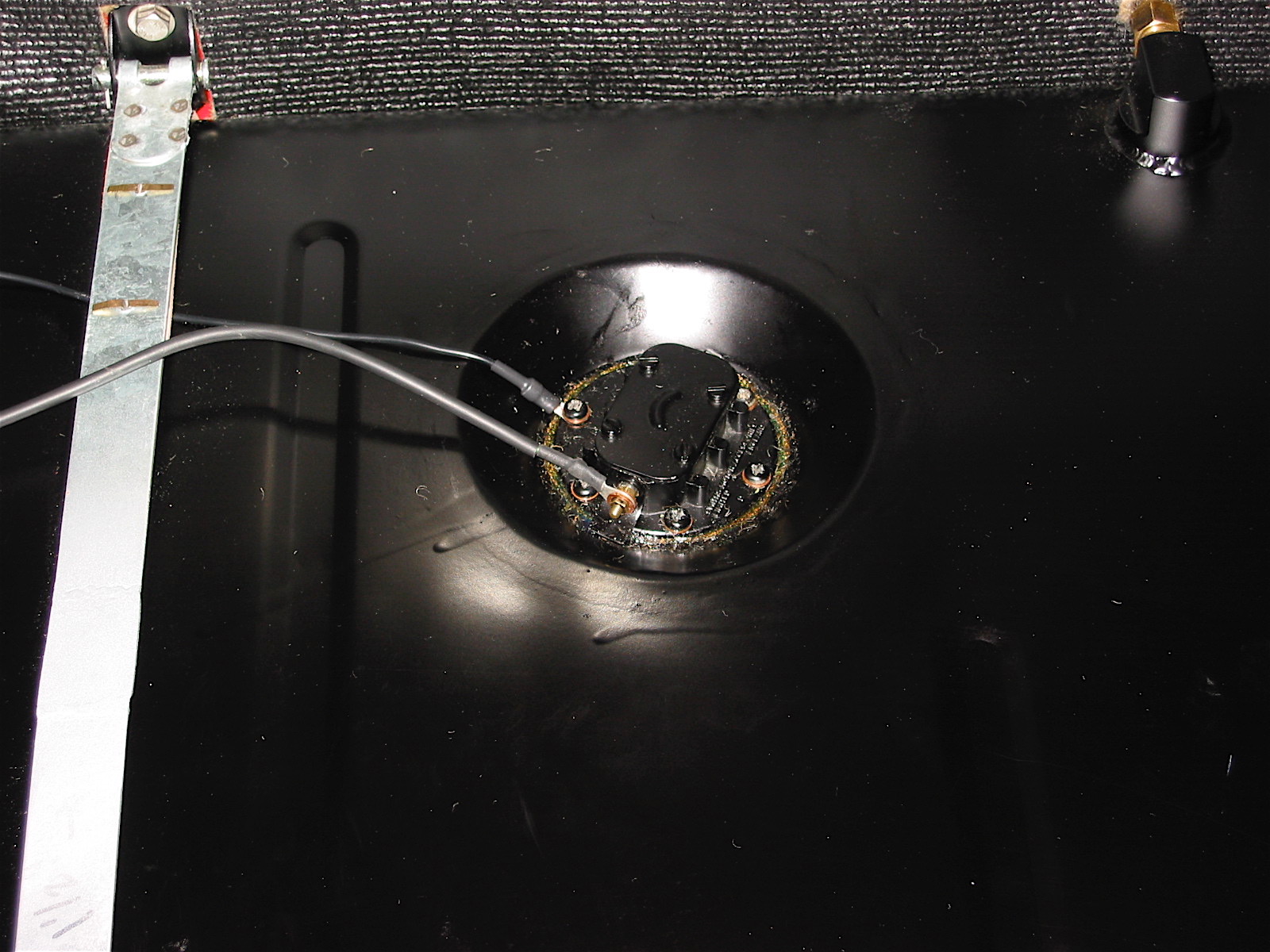
Fuel sender wiring
The spare tire staple was mounted to the floor of the boot with two flat head machine screws and the leather strap was inserted. I put the spare in place just to see how things would look and fit.
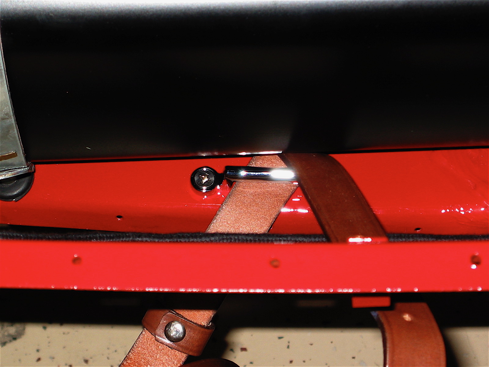
Spare tire staple
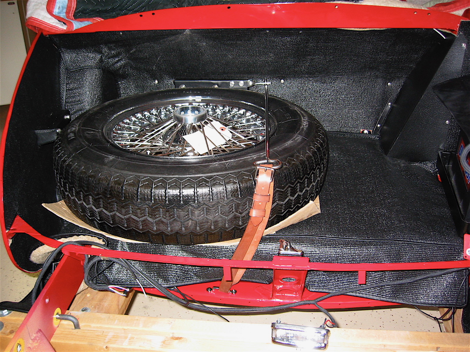
Spare tire installed
Next, I moved to installing the fuel filler neck hose and the filler neck (pipe). I tightened the lower clamp, but will wait until the shroud is installed to finally secure the upper clamp. The blue paper towel in the image to the right is just there to protect the paint until final assembly. The Aston fuel filler cap was screwed on and the corner cardboard cover was screwed on with six #6 screws and trim cups.
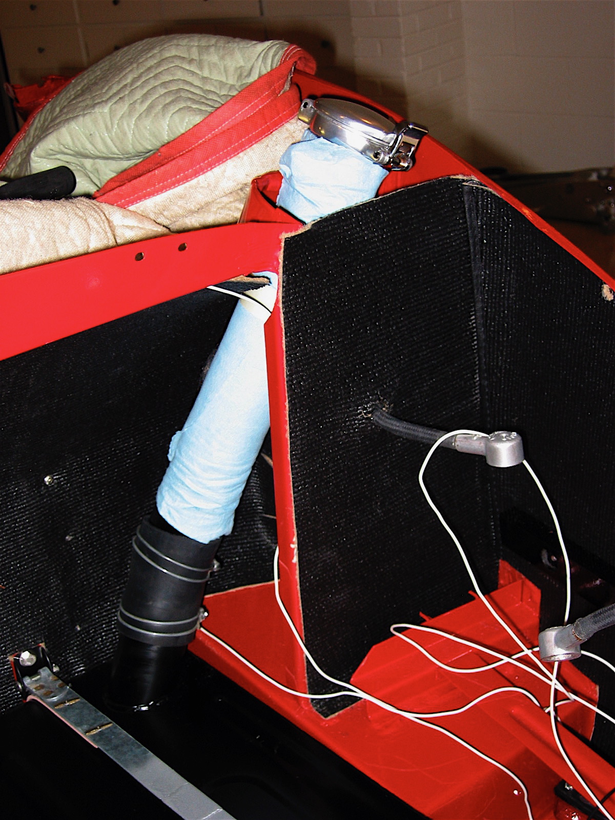
Fuel filler pipe
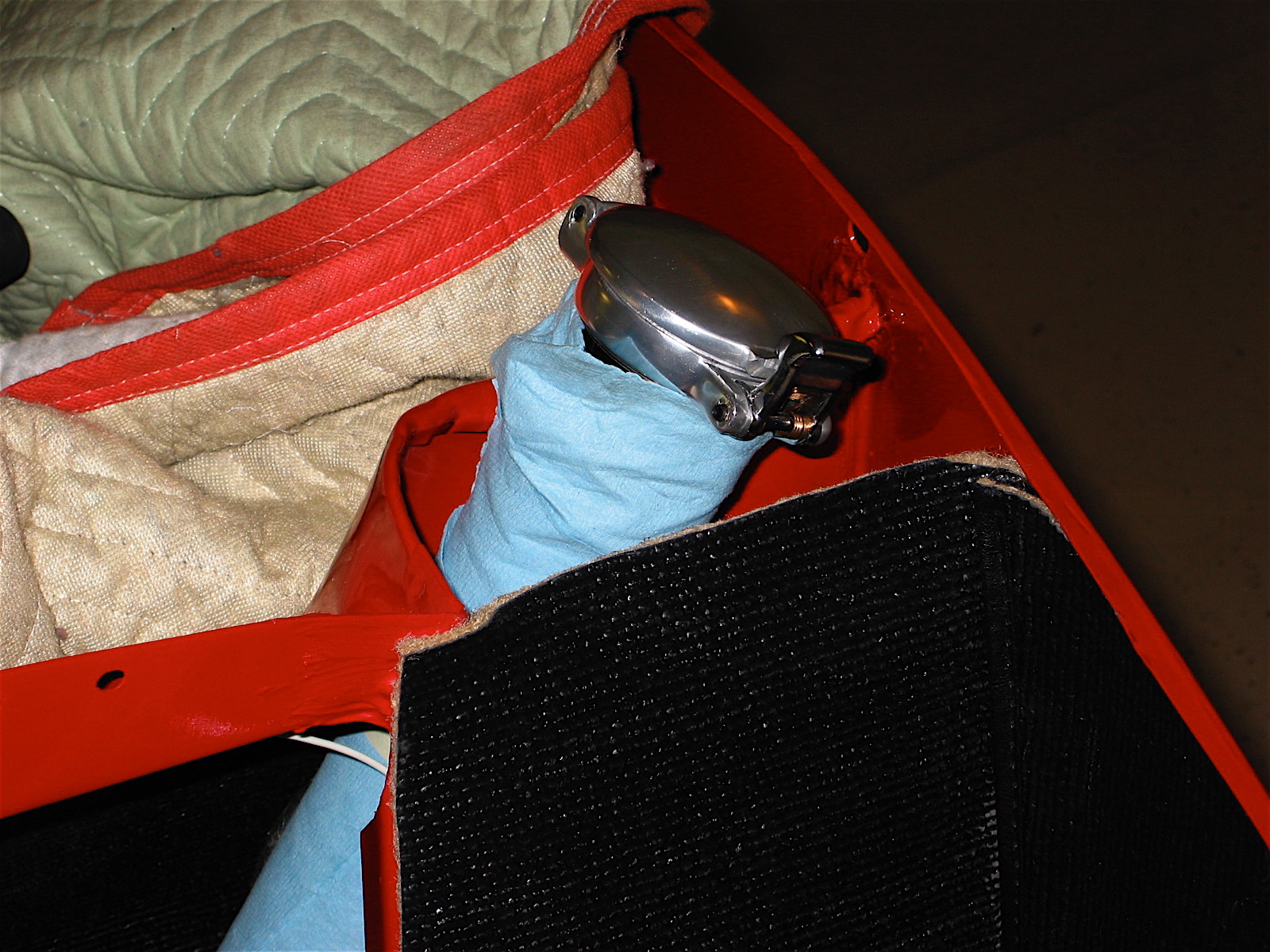
Aston Filler cap
The boot lid striker was then loosely attached to the rear skirt rail support with three 1/4” hex bolts. It will be tightened in place following the installation of the shroud and the rear boot lid.
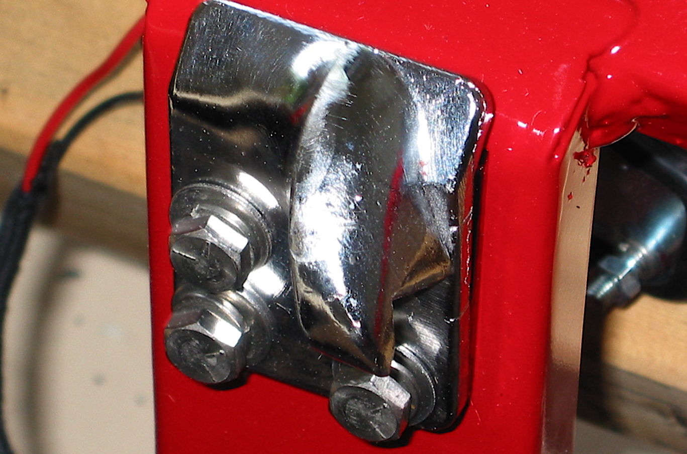
Boot Lid Striker
The choke knob and cable were the next items to be addressed. The original BT7 had its choke located below the dash, but as with later cars, I decided to place mine on the dash fascia. Because my only option was to drill a round hole in the fascia, rather than the stamped hole on the later cars with a “flat” at the top of the hole to hold the cable unit when tightening the nut on the back side, I improvised with a chrome nut on the front of the fascia as well. I actually made it by cutting off the back of an extra side curtain bezel. It fit perfectly and won’t be recognized by the untrained eye.
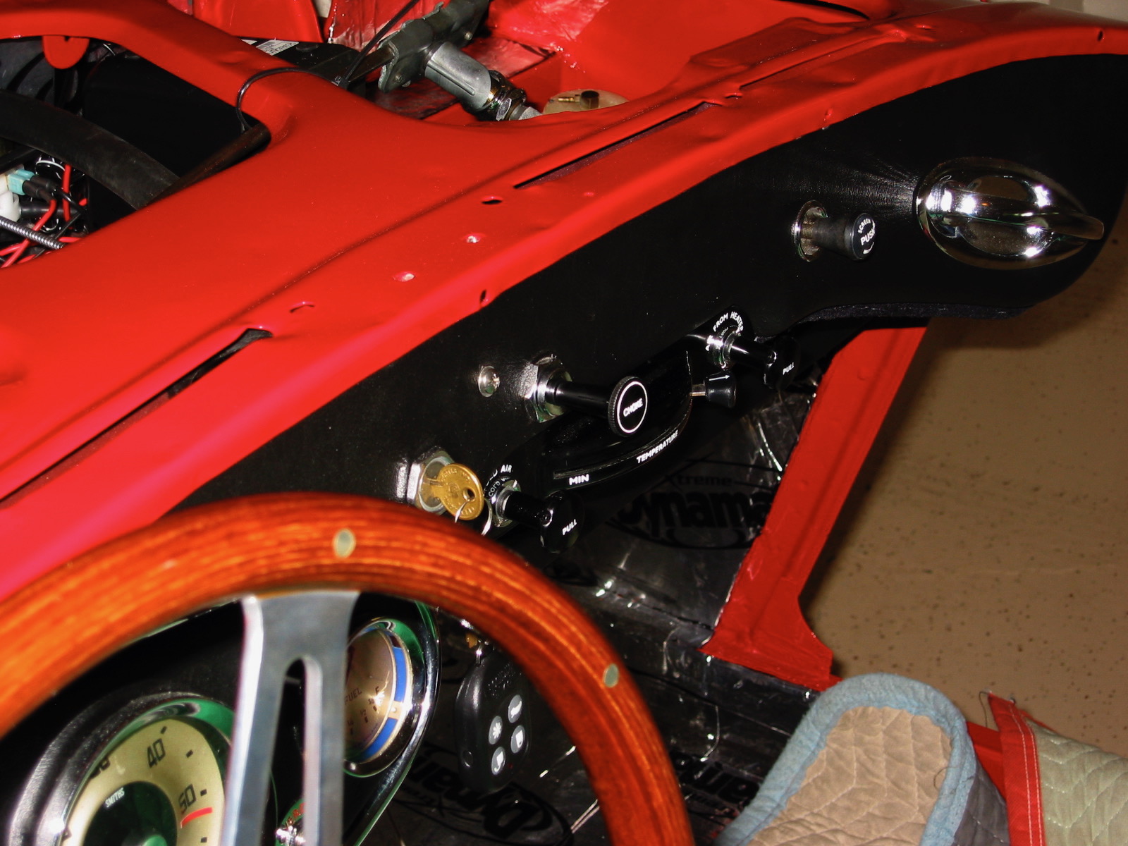
Choke Knob 2
Since I am using 2” HD8 carbs instead of the stock HD6 carbs, I also used the BJ8 choke control body bracket mounted on the firewall. Other Healey owners have reported problems with the return mechanism on the choke, so I drilled the remote control cable block and tapped the holes for two #4 stainless screws to secure the carb cables in their fittings.
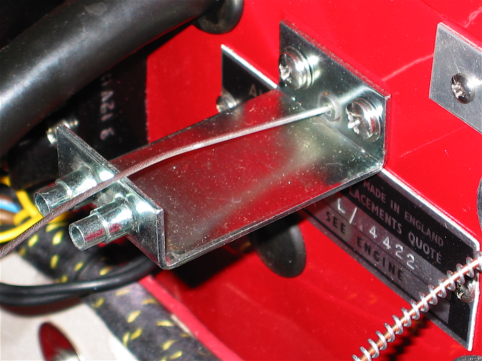
Choke Control Body Bracket

Choke Cable Block
The LH fresh air intake assembly was then installed, and the control cable was attached.
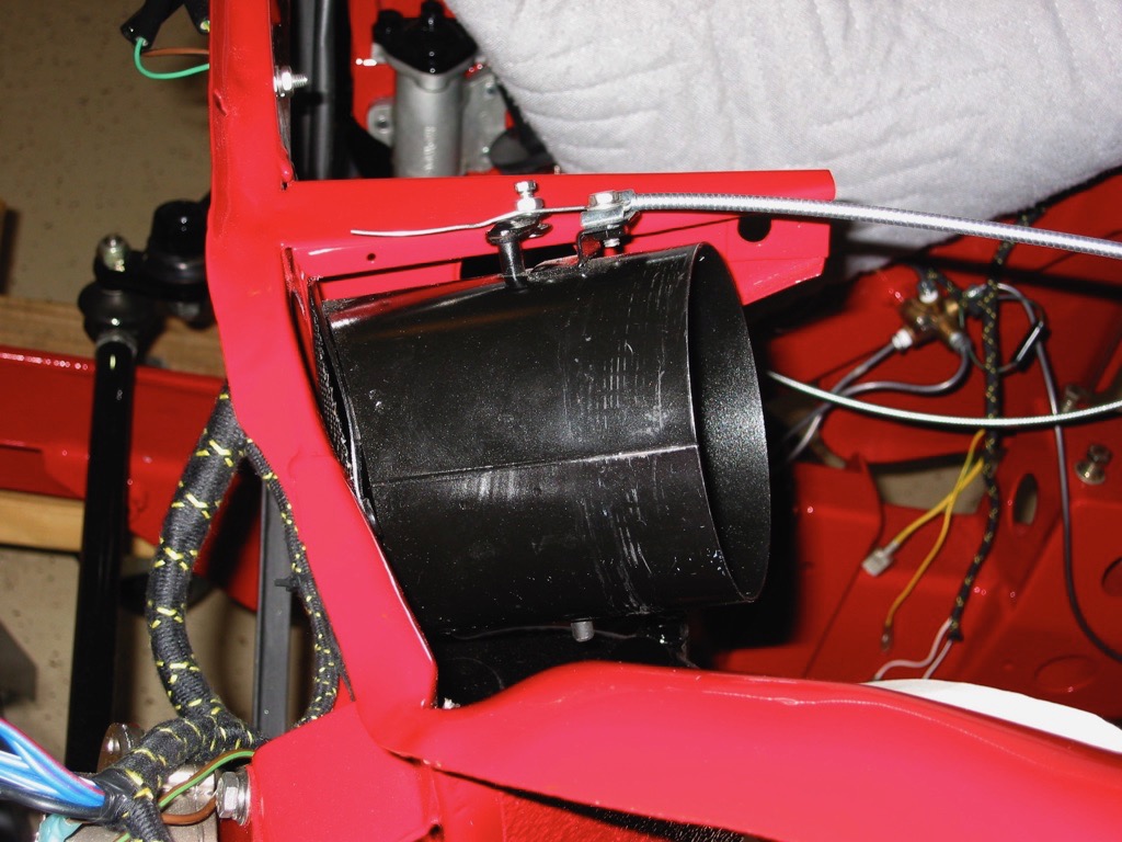
Air Control Assembly 1
The bonnet latch remote control rodwas the next item to install. While it wasn’t a problem, it would have been easier to install before the dash fascia was affixed!
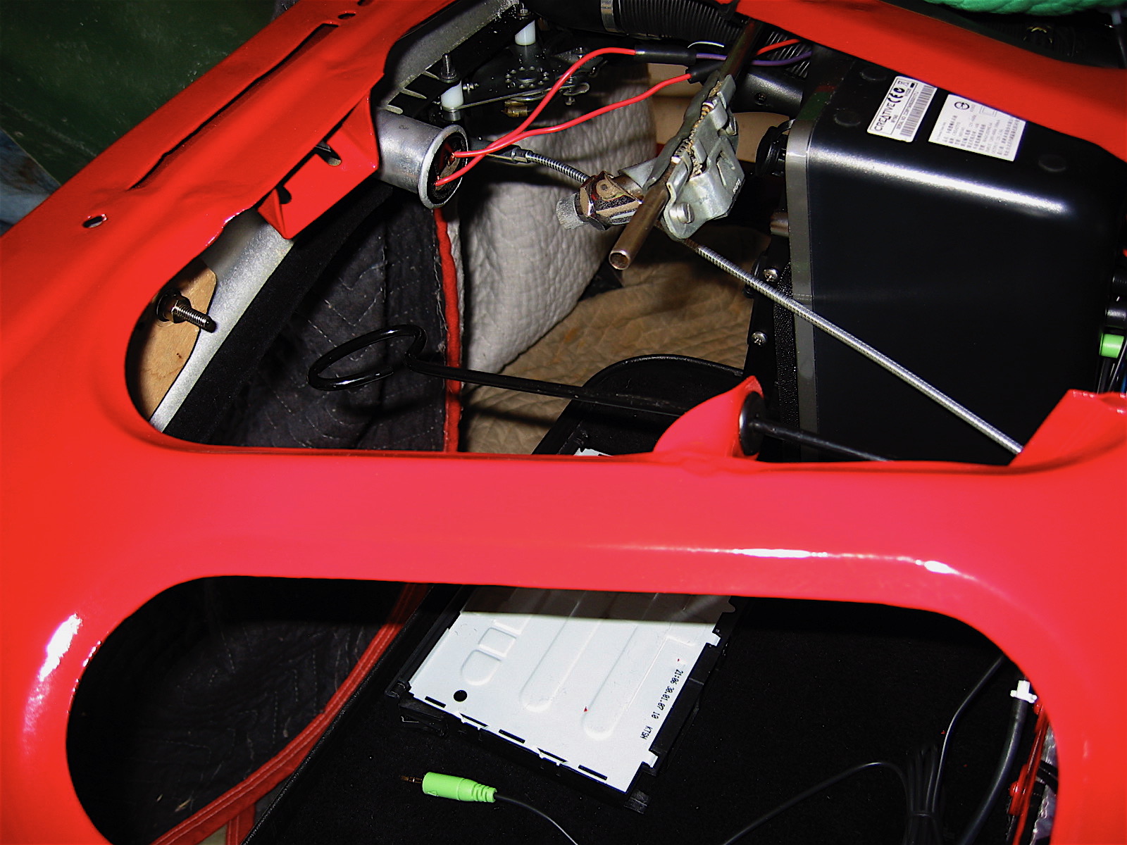
Hood latch remote control rod 1
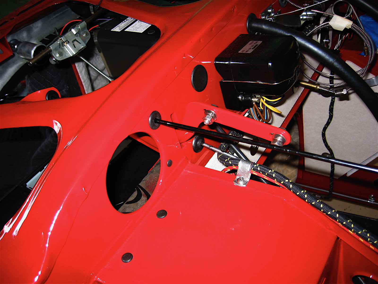
Hood latch remote control rod 2