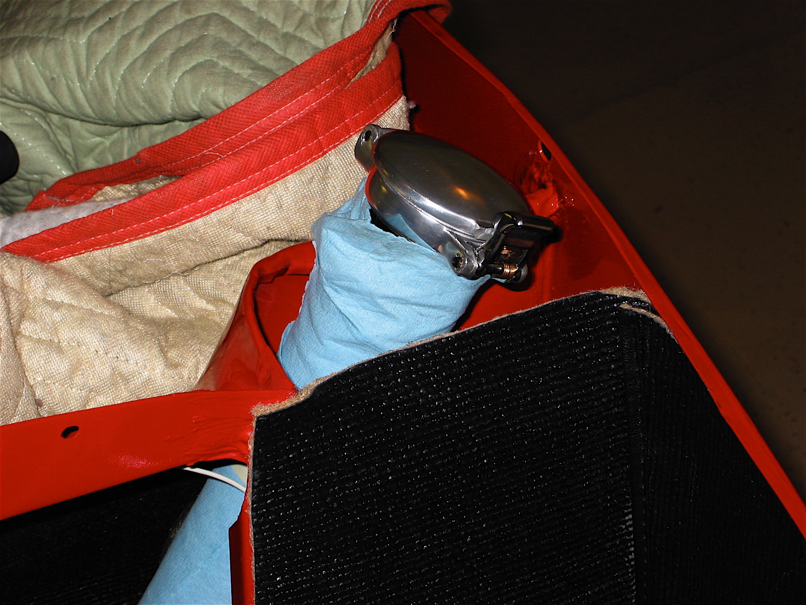
The windscreen was a very tight fit! I suppose that it should be to minimize leaks, but it took some tugging on a drift through one of the lower mounting holes in the stanchion and a lot of pushing to finally get the uppermost capscrew to thread into place. The RH side didn’t require any shimming, but the LH did. You do want to make sure that there is no undue force on the stanchions or you might end up with a broken glass! I added a little 3M caulk strip under the post pad seals and between the windscreen frame seal and the post pad. I decided to run the seal under the post pad, though consulting with the “experts” resulted in at least three ways to do this job: under the pad, between the pad and the post, and cut off flush with the pad. I am using post mounted driving mirrors from Cape International, so they were mounted at this time and tightened through the posts.
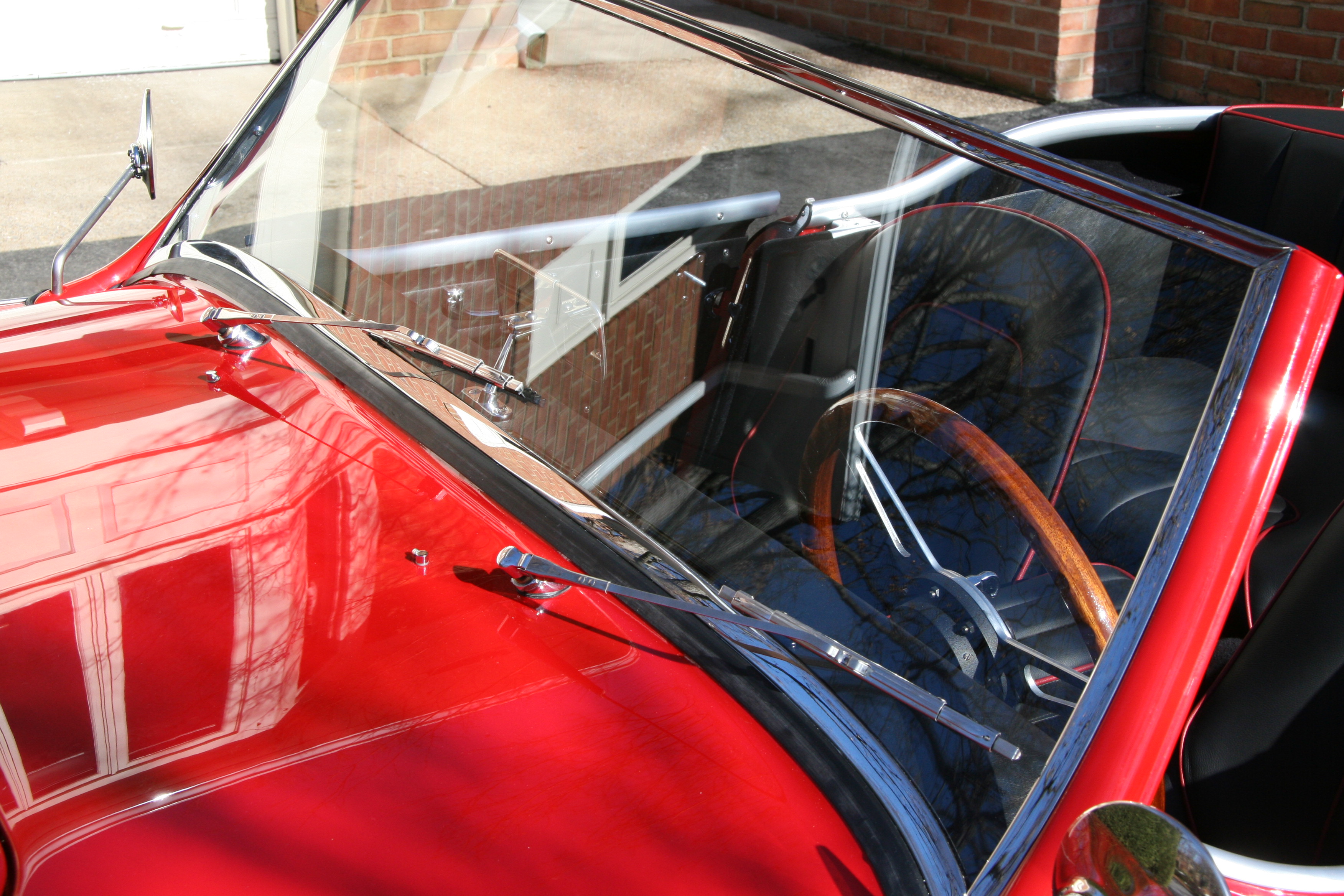
Windscreen and wipers installed
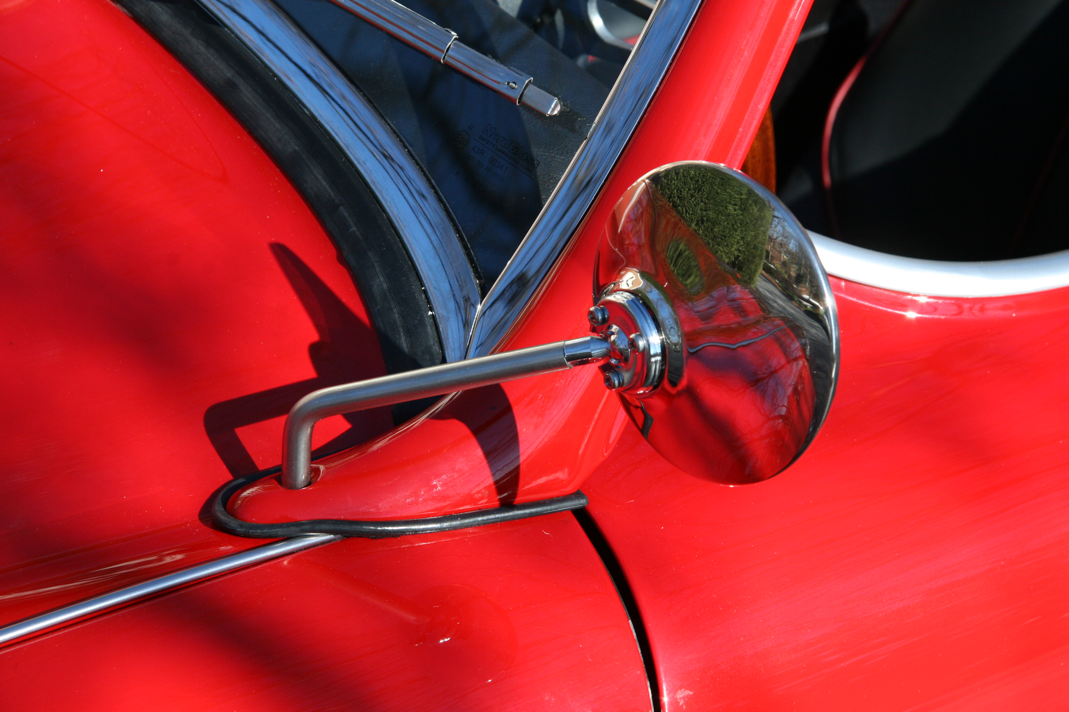
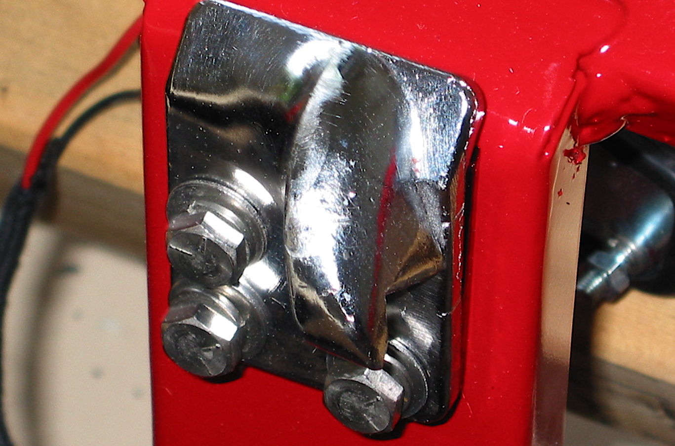
Capesport Mirrors
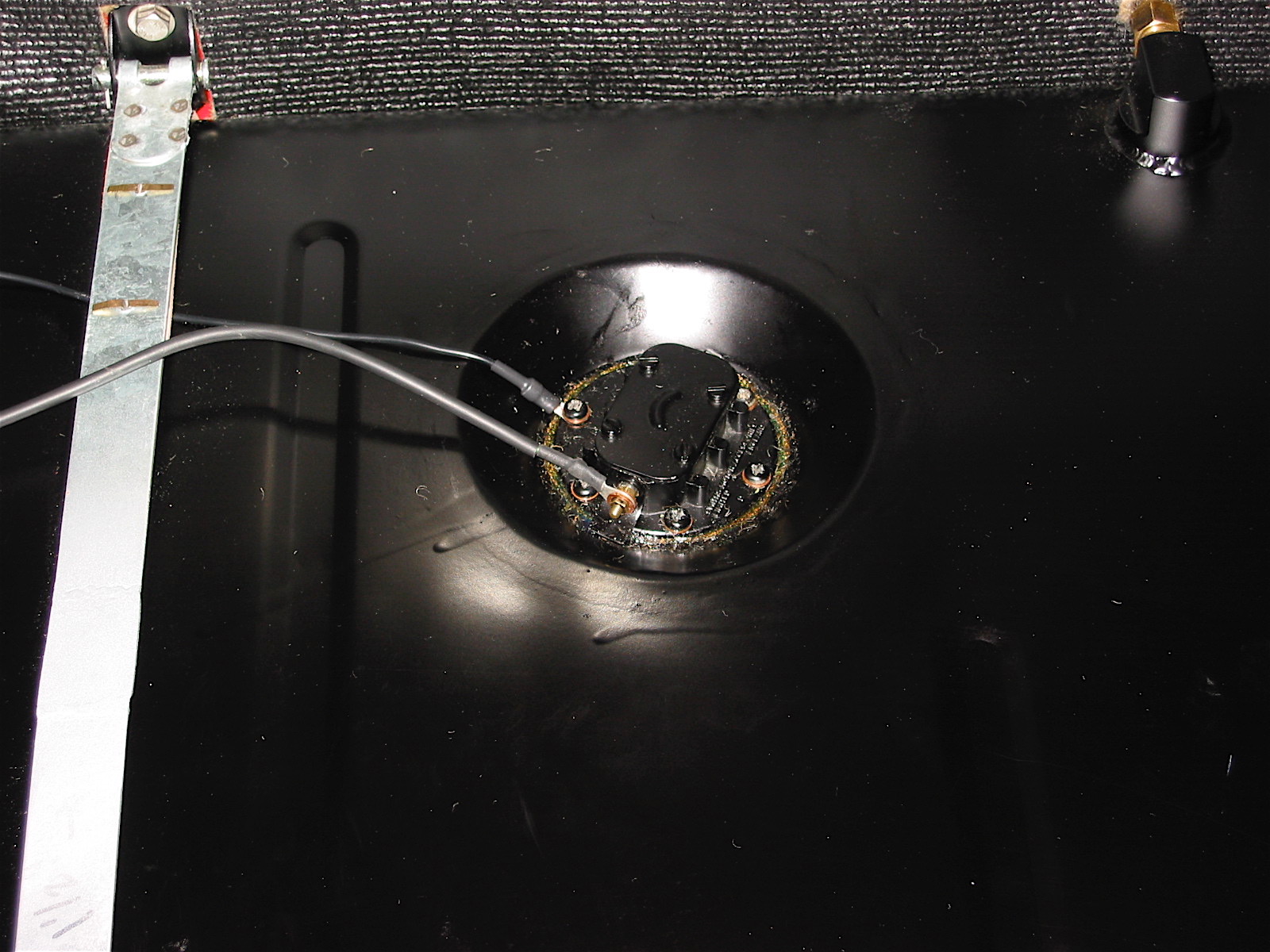
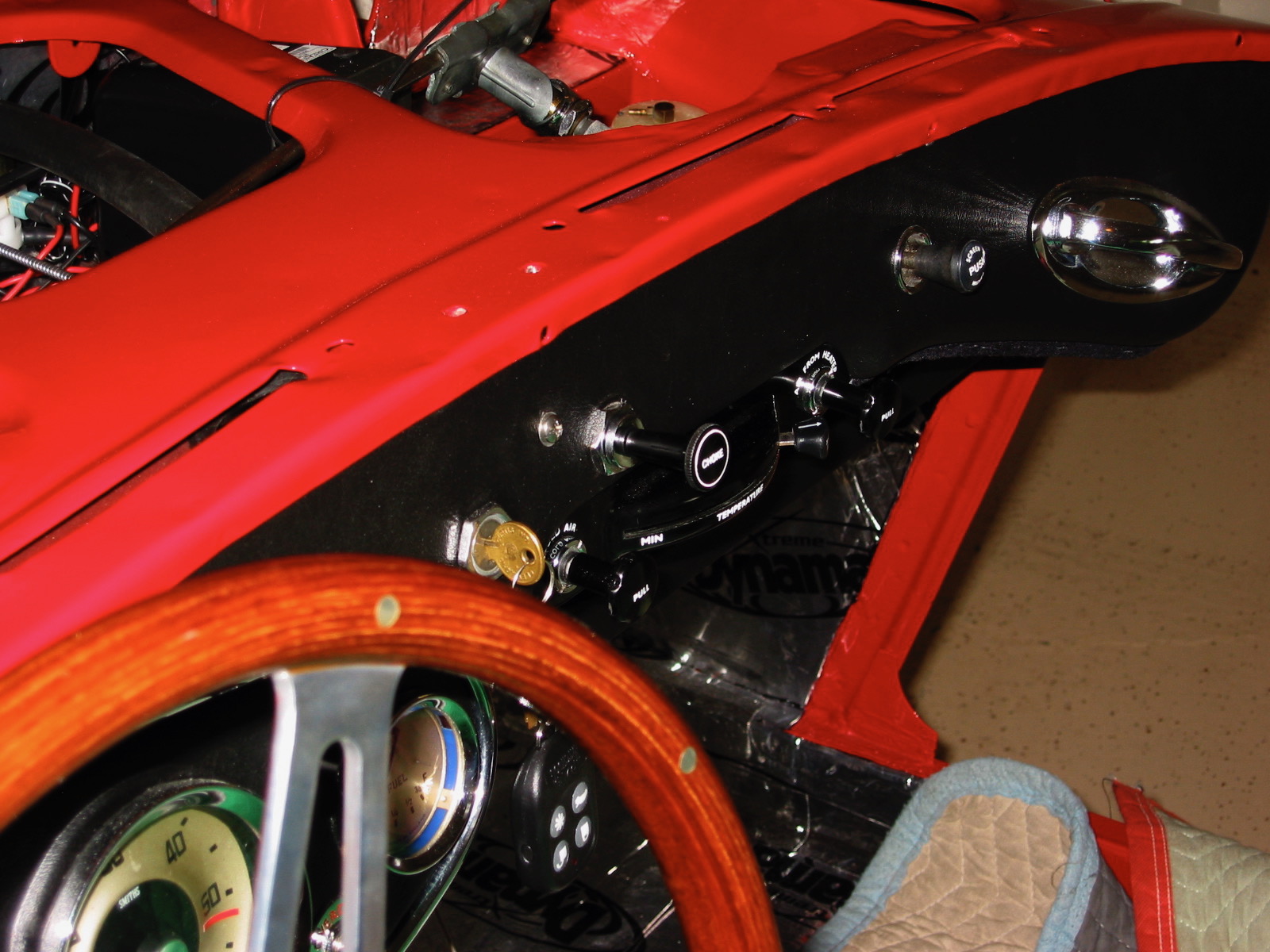
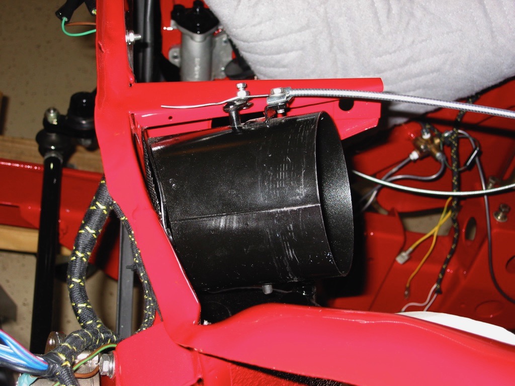
After finishing the windscreen, I fixed the original “rainbow” wipers with new rubber to the wiper posts and following the addition of some windscreen washer fluid to the parcel tray mounted fluid reservoirtried out the wipers. All worked fine, including the intermittent wiper rheostatand electric washer pump I has installed previously. The kit from Ed Esslinger also turns on the headlamps when the wipers are activated – a requirement in many states now.
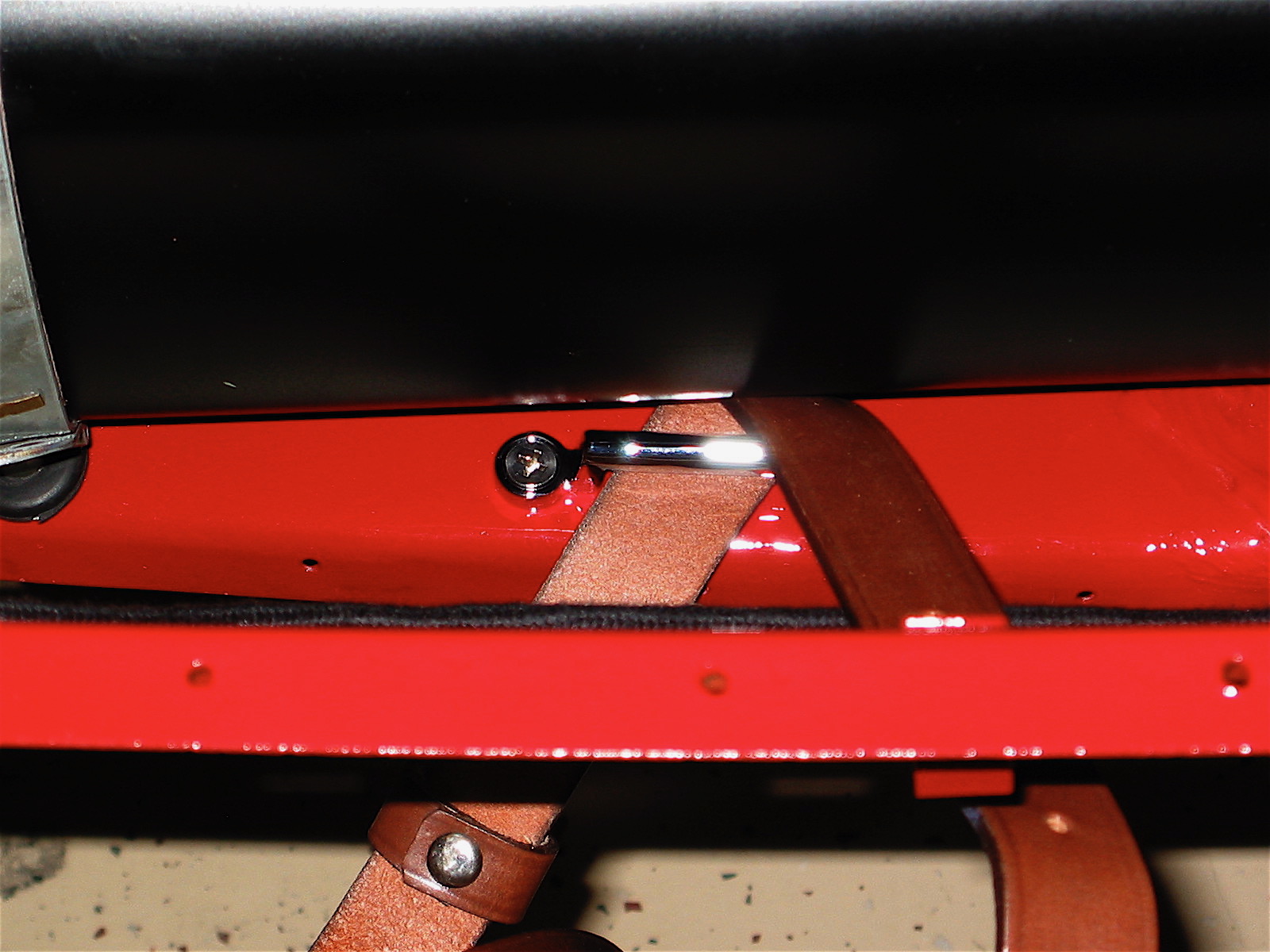
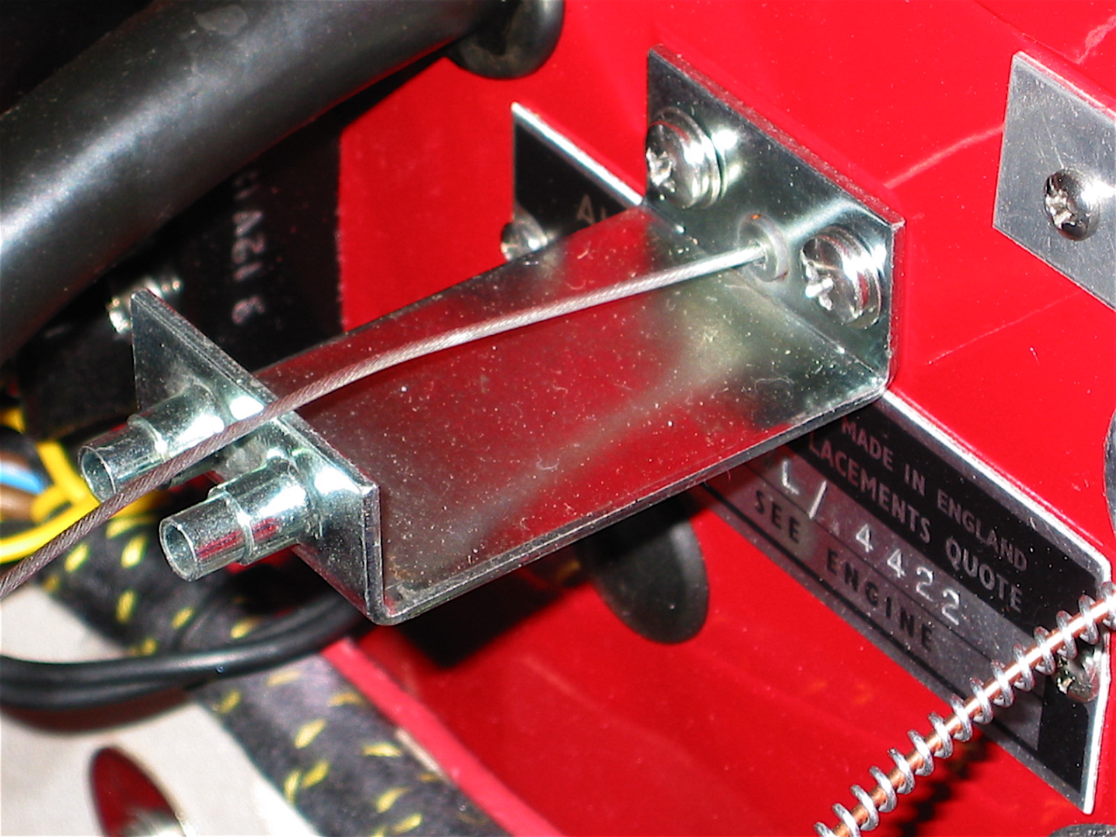
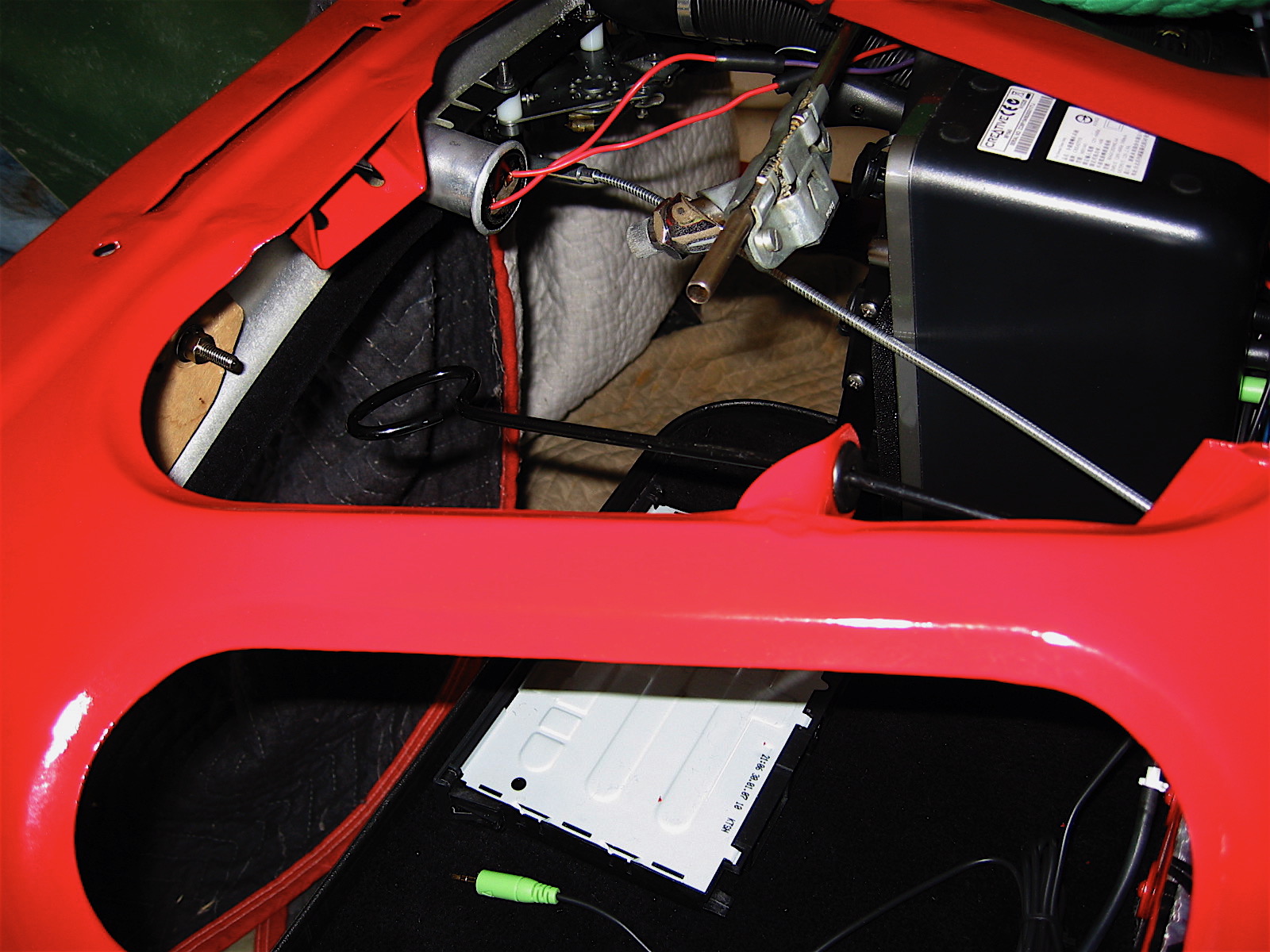
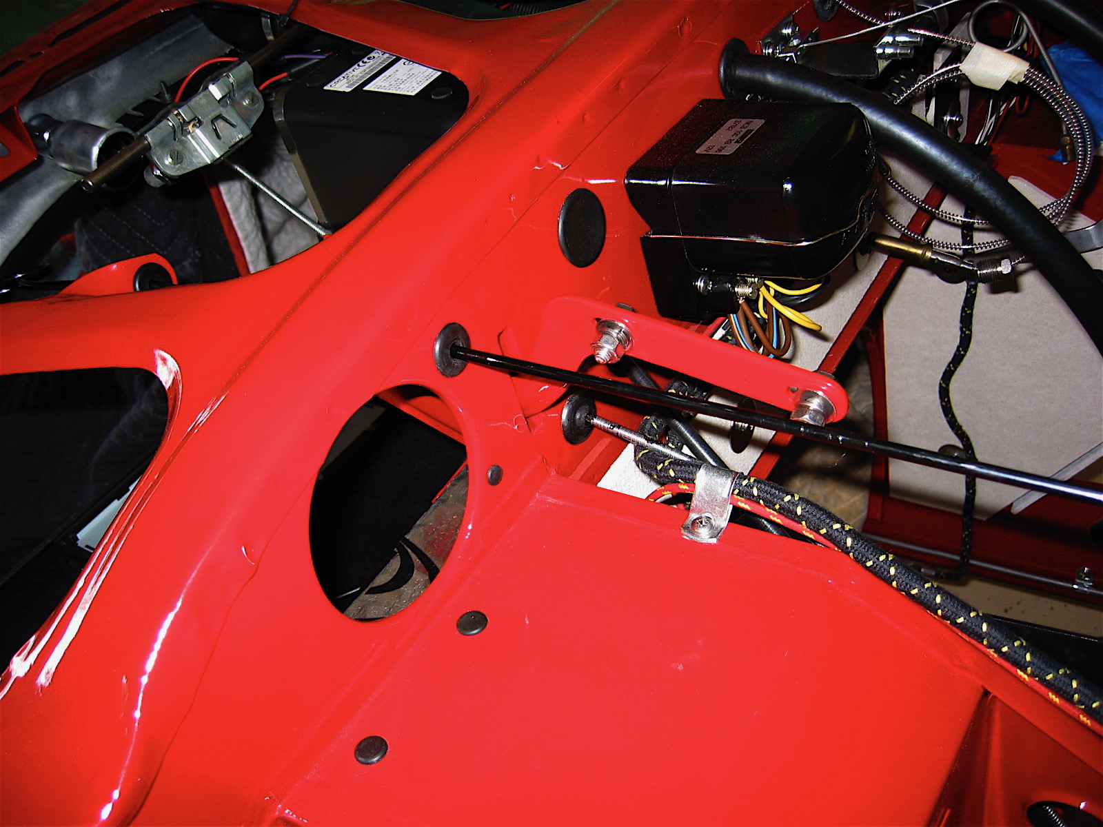
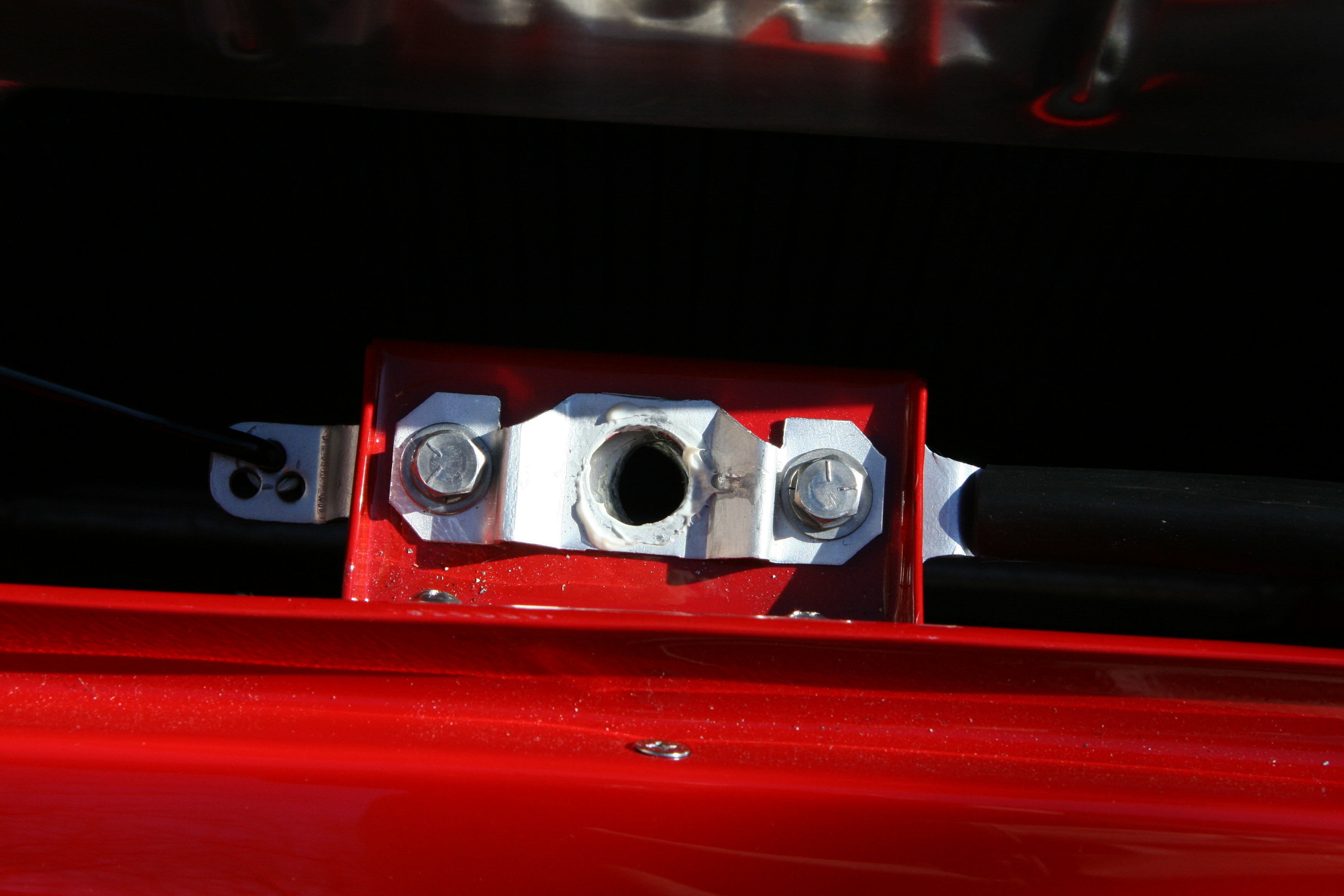
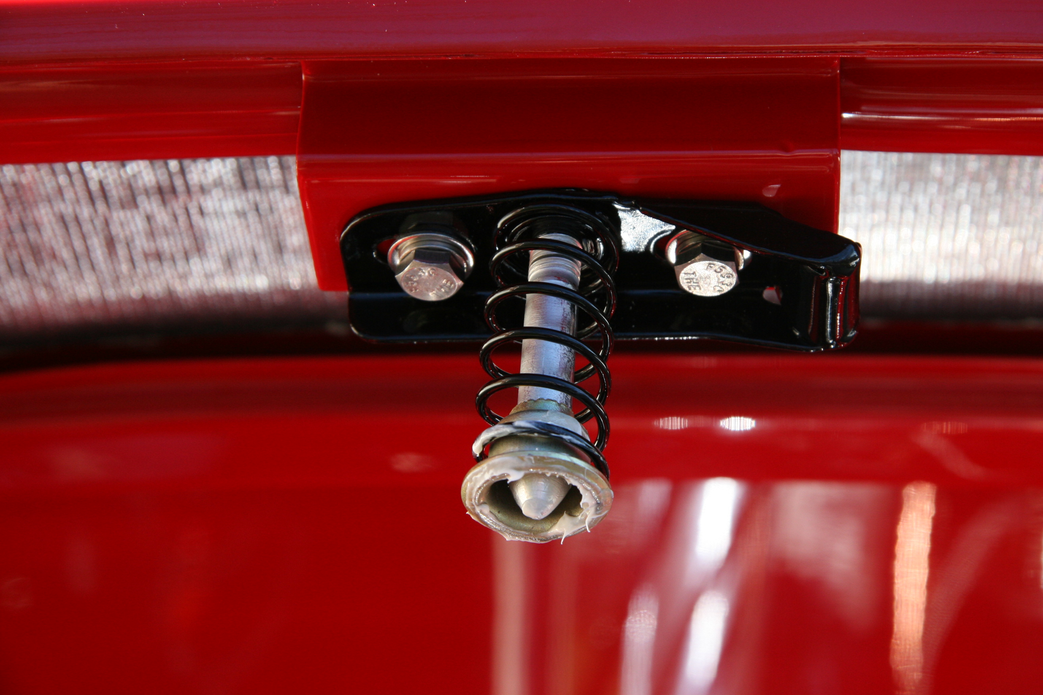
Next was the installation of the bonnet. I first removed the striker pin assembly so that I could have the bonnet lie flat in the surround. Four 1/4” bolts with the heads to the outside are used to fasten the hinges to the bonnet hinge brackets. This process took some adjusting to get things right and at least one assistant is essential! After getting the bonnet lined up I re-secured the striker pin assembly to the bonnet and adjusted it and the bonnet latch support bracket to align all. The anti-rattle spring was then connected to the hood latch remote control rod and the bonnet release mechanism was tried with success.
Bonnet Latch Assembly
Strike Pin Assembly
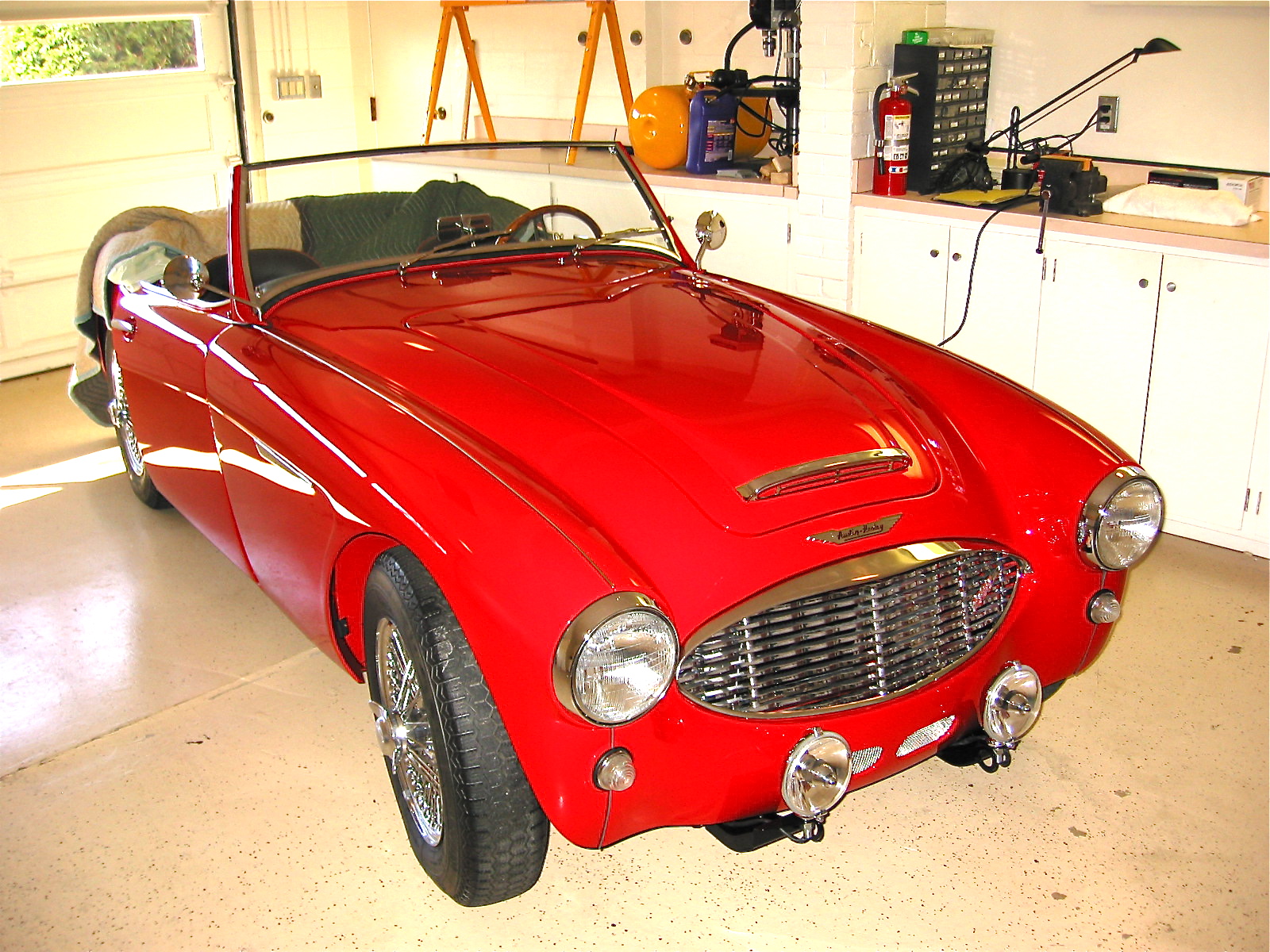
Bonnet down
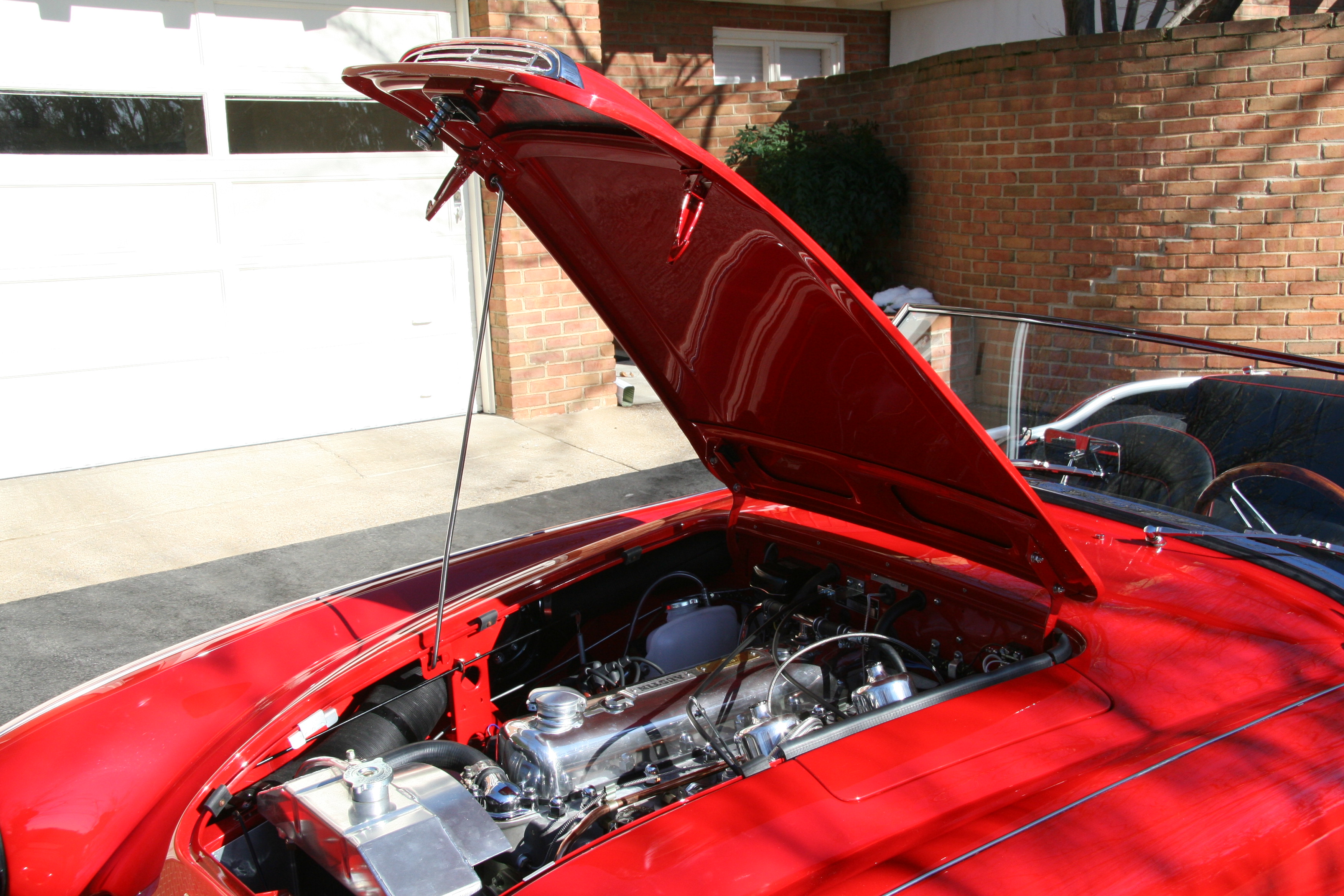
Bonnet Up