February 13 , 2004
Rear Disc Brake Conversion
Decided to convert to disc brakes in the rear of the car and purchased the kit from Cape International. The kit consisted of two machined caliper mounting brackets, two Jaguar calipers including handbrake calipers, linkage for the handbrake, two disc rotors, templates for modifying the axle flanges and mounting hardware. The instructions provided assume the axle is on the car, but it appeared that the kit would be easier to install if the axle was removed from the car. I hope that the assembly can be inserted into the car from the right side once complete.
First modified the axle flanges using a dremel tool. The templates were used as a guide to mark the axle for cutting. The axle was repainted following the cutting. The caliper mounting brackets (not handed) were mounted to the axle flange using four 3/8” UNF bolts and nylock nuts.
rear caliper bracket 1
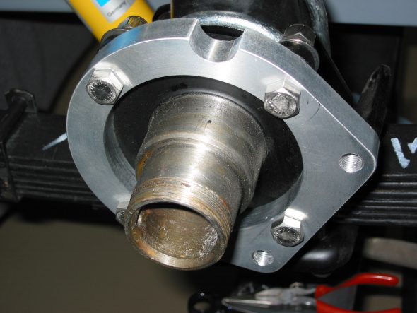
rear hub removal
rear hub spacer,washer,nut
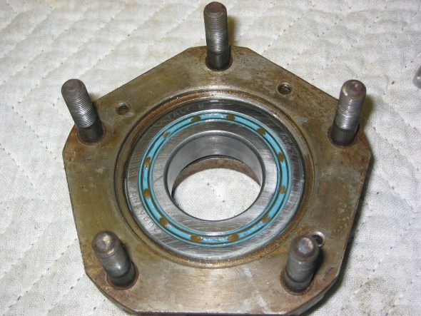
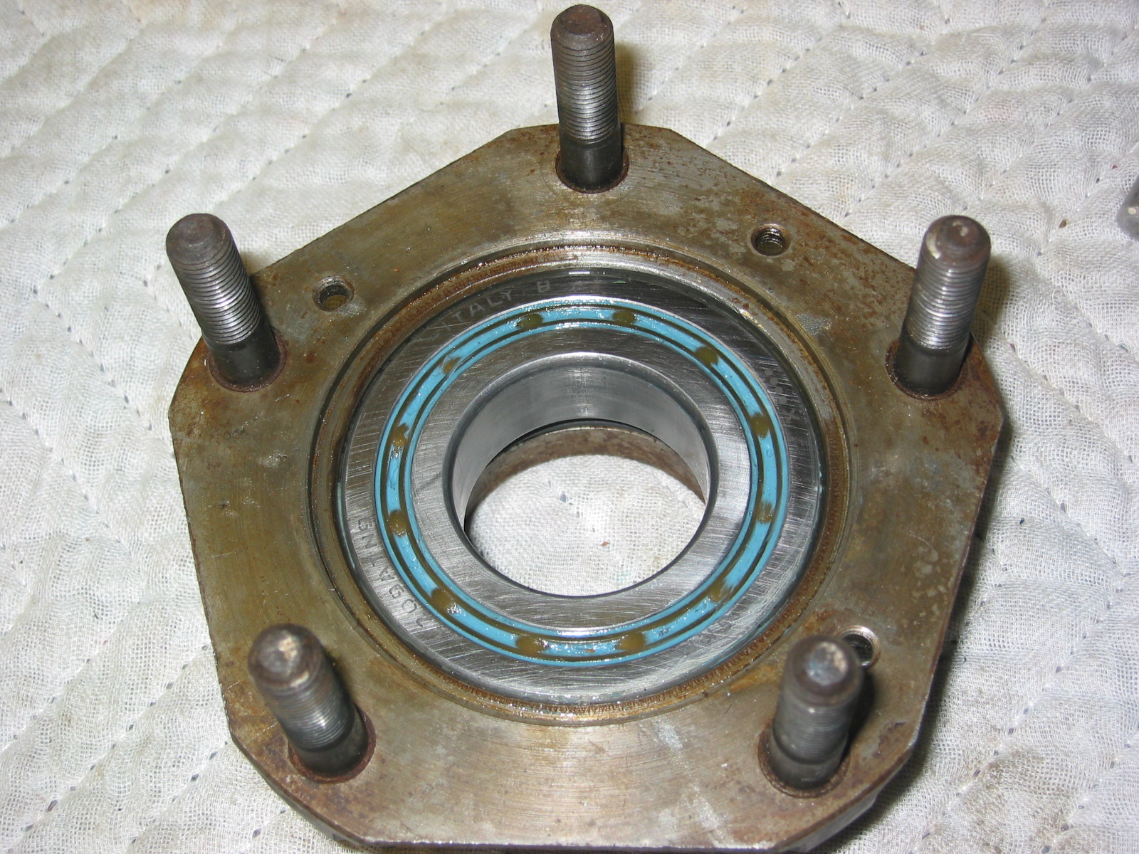
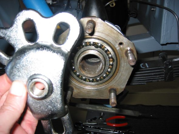
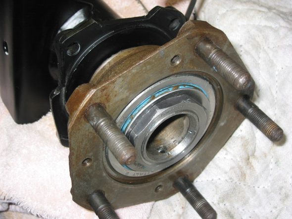
rear hub bearings
New rear bearings, and seals were pressed into the hubs. The bearing should protrude .001 to .004 from the surface of the hub after the outside washer and “O” ring seal are installed. Care must be taken to not drive the hub onto the axle too far or the bearing will be pushed too high. The tab washer and hub nut were then installed and tightened. The tab washer will not be bent down over the nut until absolute final assembly. The paper gasket was not affixed at this time since the half shafts will need to be pulled later for the installation of the differential. The half shafts were inserted and fastened to the hubs with one flat head tapered screw with a pozidrive head.
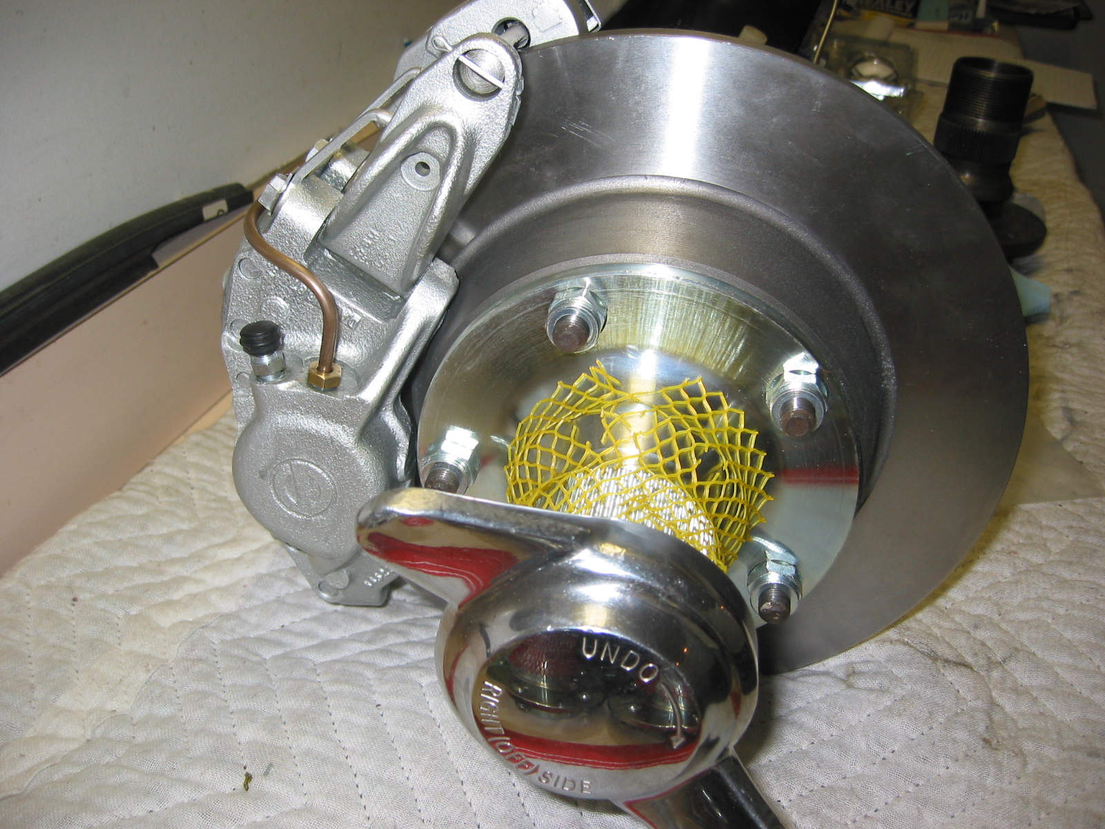
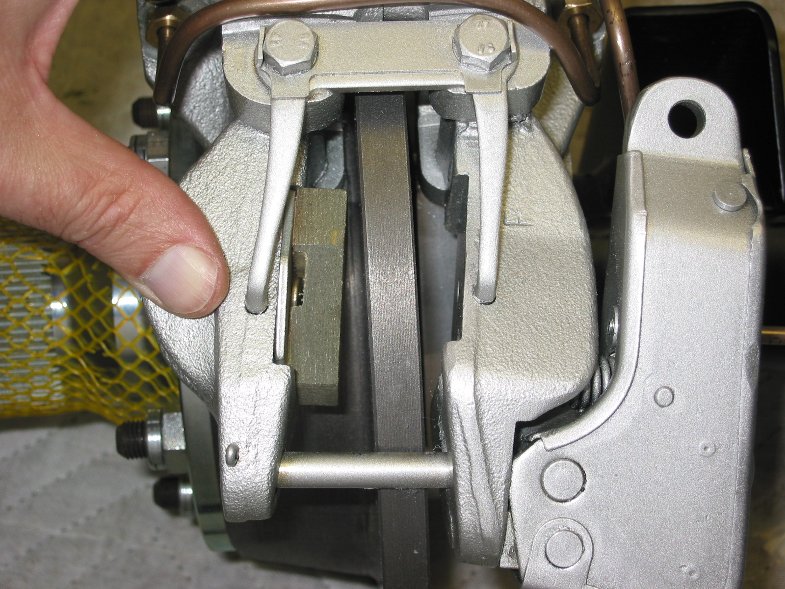
The new disc rotors were then attached with new hub extensions for the wire wheels. Care should be taken to put the proper hub extension on each side. Ten new conical lug nuts were provided in the kit. The calipers were then slotted over the disc rotors.
The first flaw in the Cape International kit was discovered at this point. The inside of the caliper rubbed against the rotor preventing free turning of the disc. A grinder was used to remove some material so prevent rubbing. It was then discovered that the outside of the disc also contacted the adjusting screw on handbrake caliper. The grinder was called to action again. Once these modifications were made, the caliper slotted over the caliper and mounted easily, aligning precisely over the mounting holes on the provided mounting brackets. Two 7/16” UNF bolts were used for each caliper mounting. The bolt heads are drilled so that they may be “wired” to prevent loosening.
The calipers were painted Eastwood Silver wheel spray with a clear coat. The caliper units had a bronze anodized finish as delivered.
The second flaw in the kit was the lack of inclusion of the short brake lined used to connect the two sides of the same caliper. An email to Steve Norton resulted in the pipes being shipped right away. Once received the pipes were bent and installed without difficulty. The two brake pipes running along the axle were rebent to work with the new calipers.
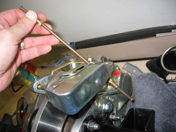
rear caliper brake line
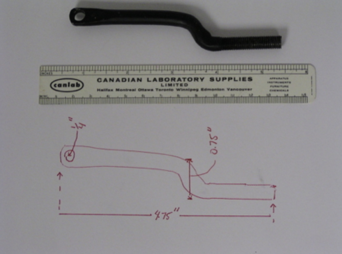
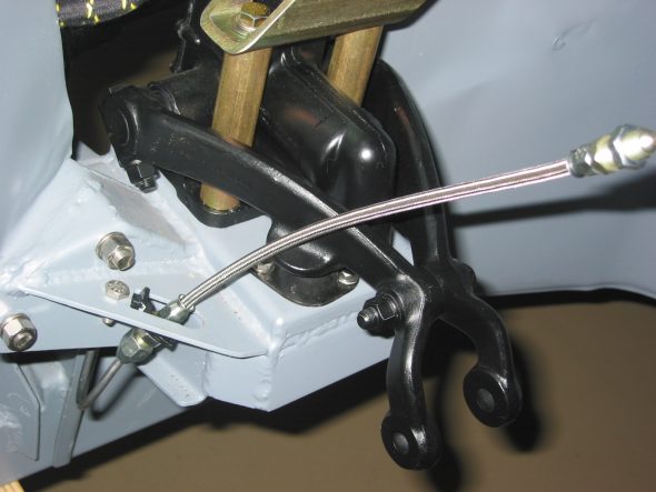
The third flaw was the discovery that the short rod provided for the link between the handbrake caliper on the right side of the car and the rotating handbrake lever did not come close to fitting. This is when I discovered quite by accident a web site created by Ed Driver in Canada. His web site contained a detailed explanation with photos of his installation of the Cape International disc conversion. He had run into the same difficulties and had fabricated a new short rod after receiving little satisfaction from Cape. He graciously sent me a photo and scale drawing of his new rod to use as a template for my application. Lifesaver!!
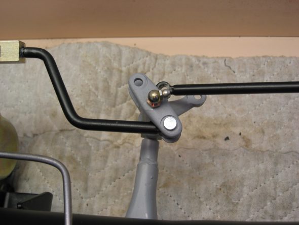
handbrake link rods 1
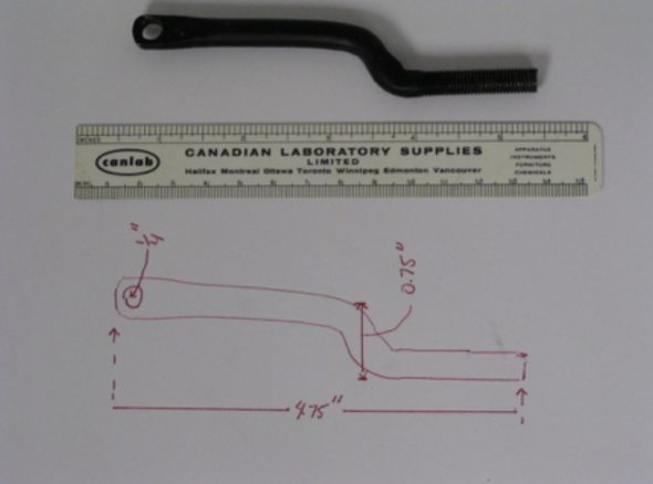
Disc Brake Custom Handbrake Connecting Rod

rear brake hub assembly

Handbrake caliper pad 4
March 24 , 2004
Return to Front Suspension Assembly
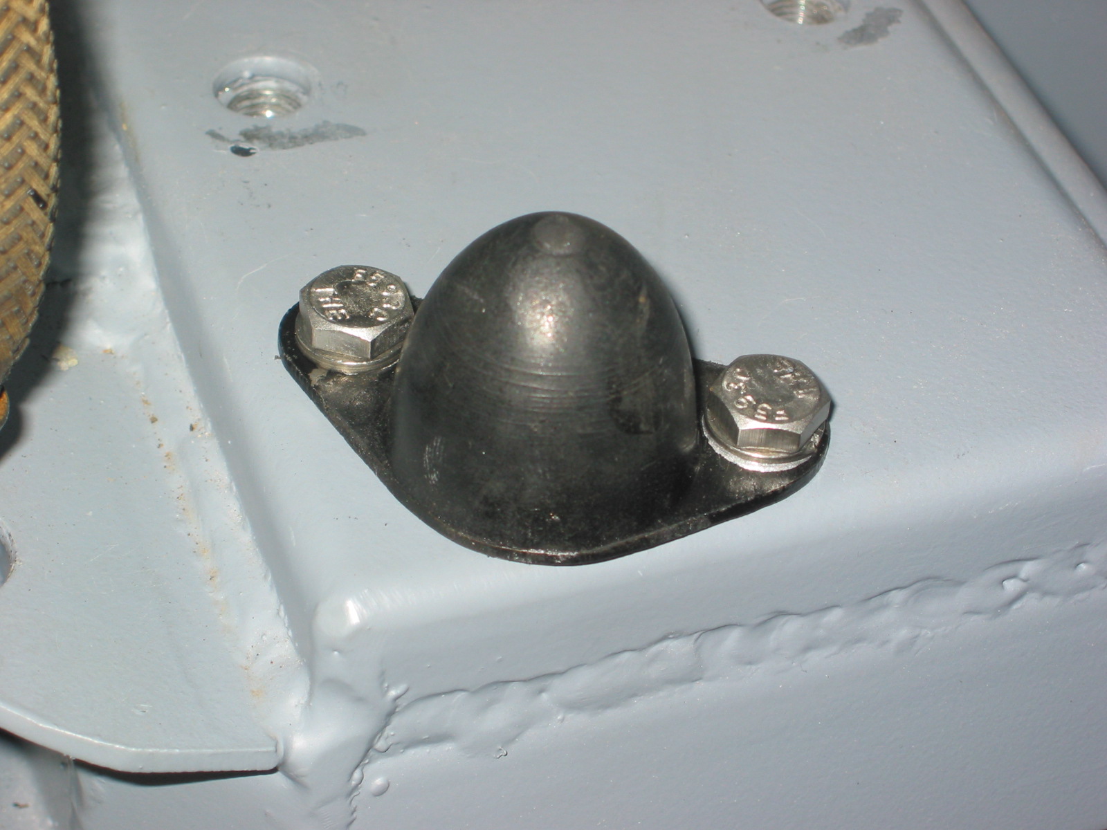
Shock Rebound – Installed the front shock rebound bushing on the shock tower.
Front Shock Rebound buffer
Caliper Brake Lines – Installed new stainless steel brake lines to the front calipers ordered from Cape International.
Stainless Brake hoses
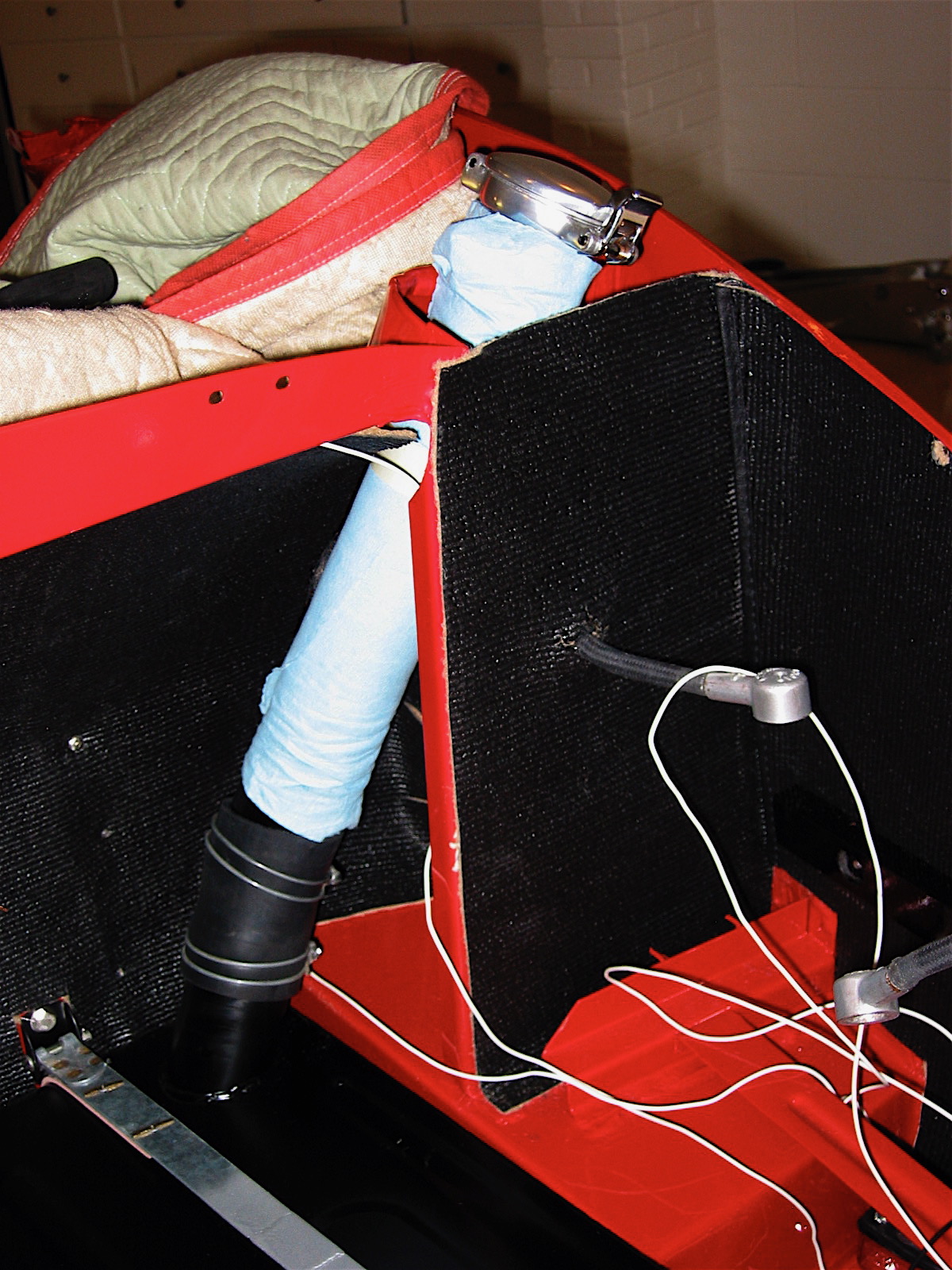
Fresh Air Intake Clip – Installed the clip for the air hose to the front wheel arch.
Air hose wheelwell clip
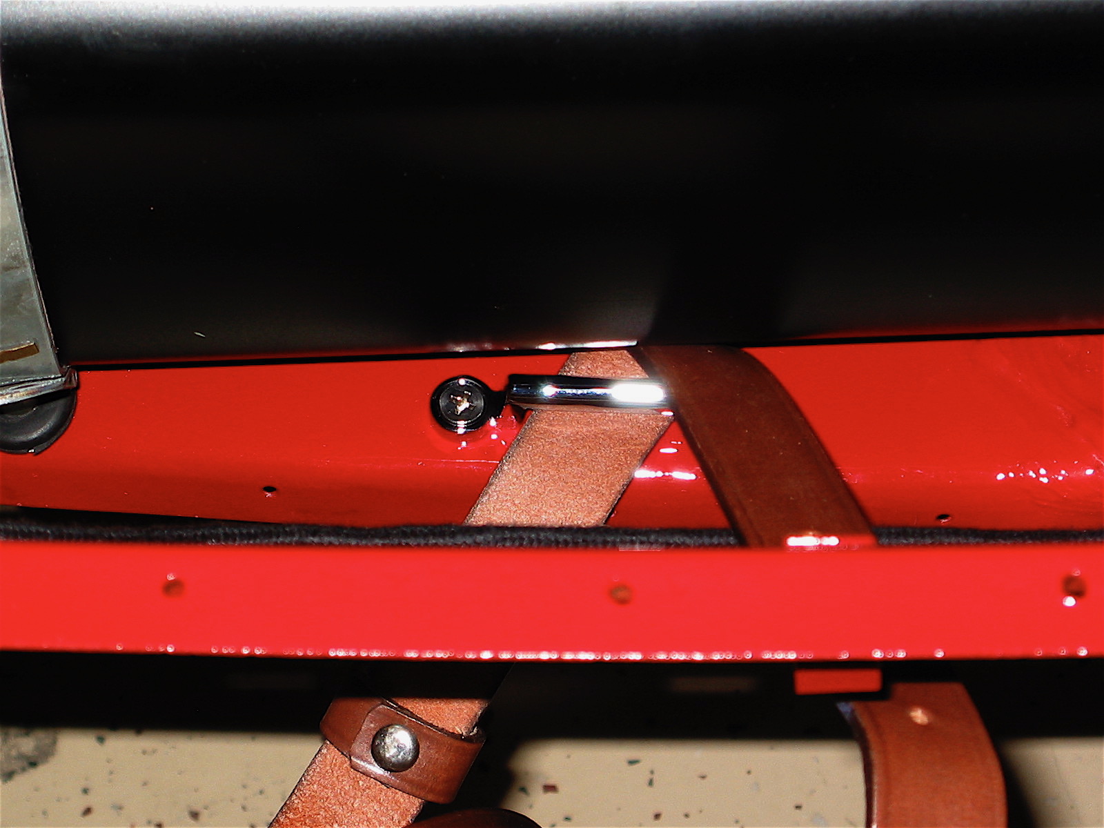
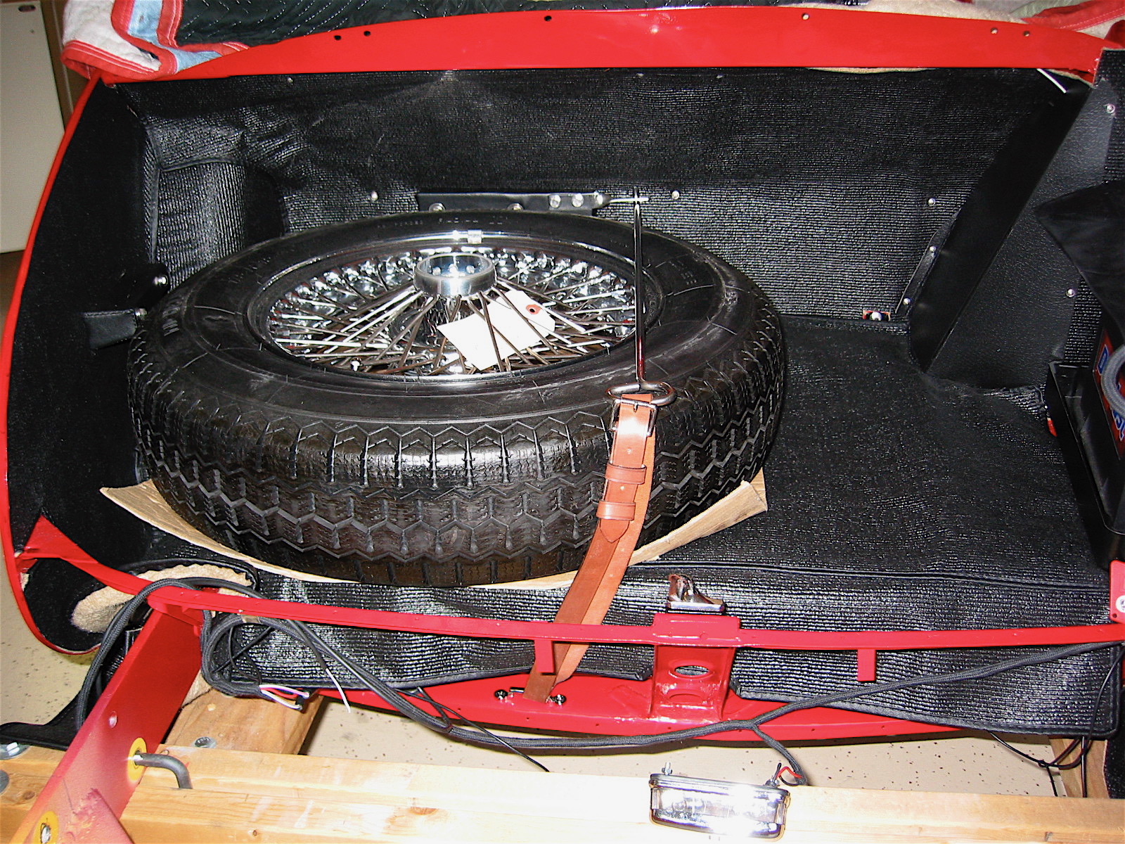
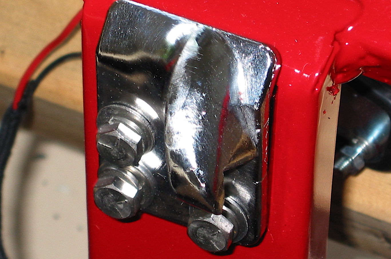
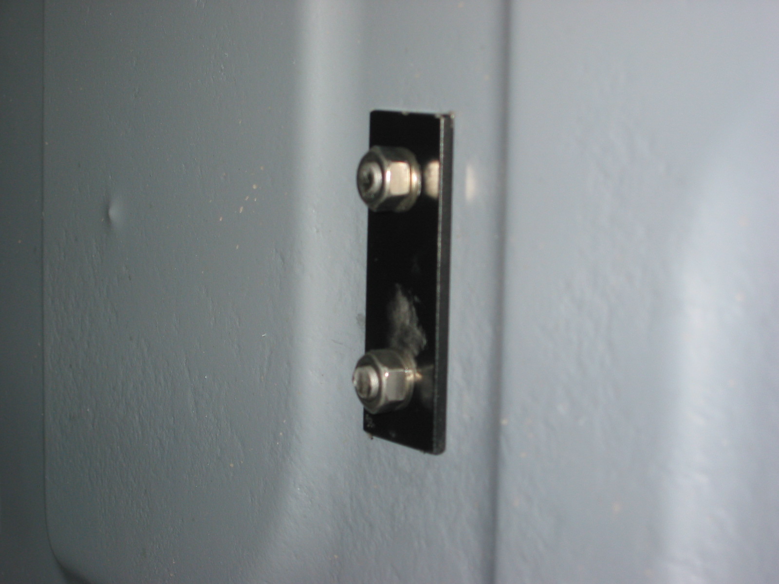
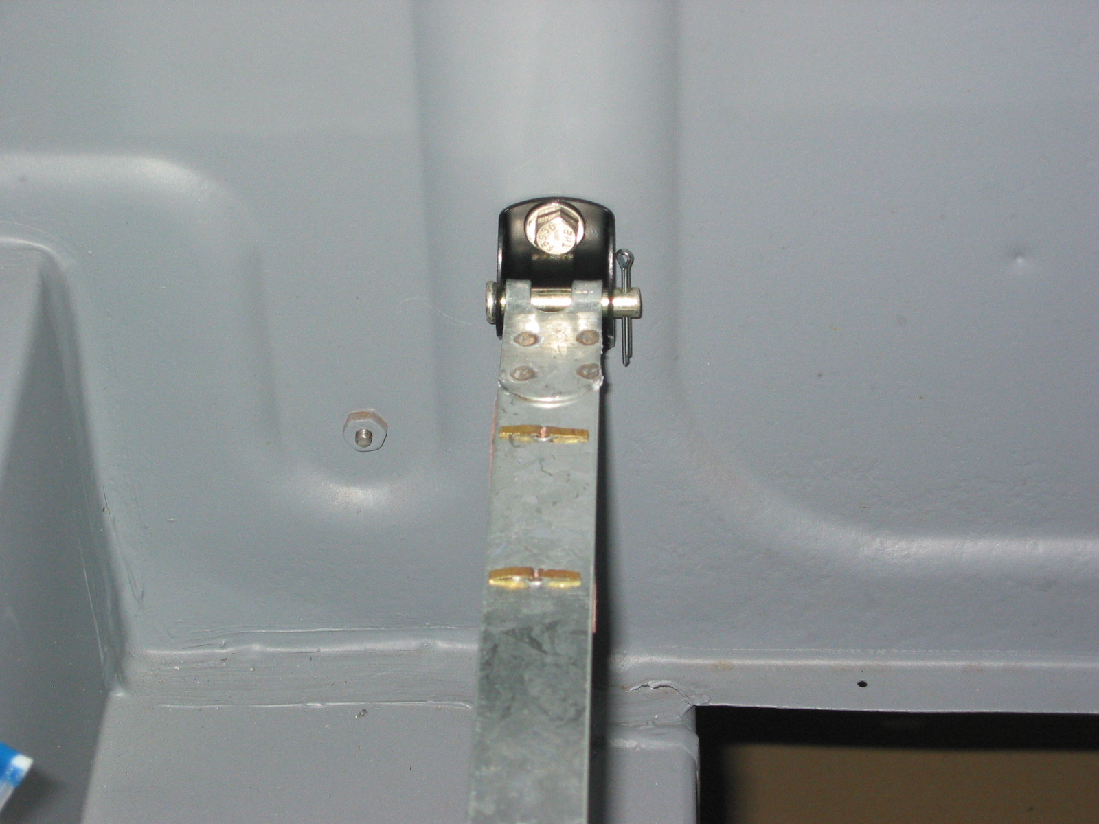
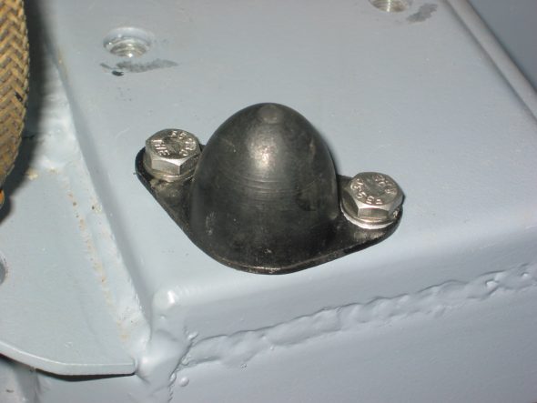
Fuel Tank Straps – Installed the two fuel tanks strap brackets to the rear boot panel. Each bracket has a backing plate on the other side of the boot panel. Note that the bracket curve Is on the top of the bracket.
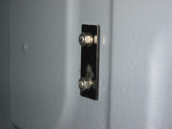
Fuel tank strap bracket 4
Fuel tank strap bracket 3
Fuel tank strap bracket 2
March 24 , 2004
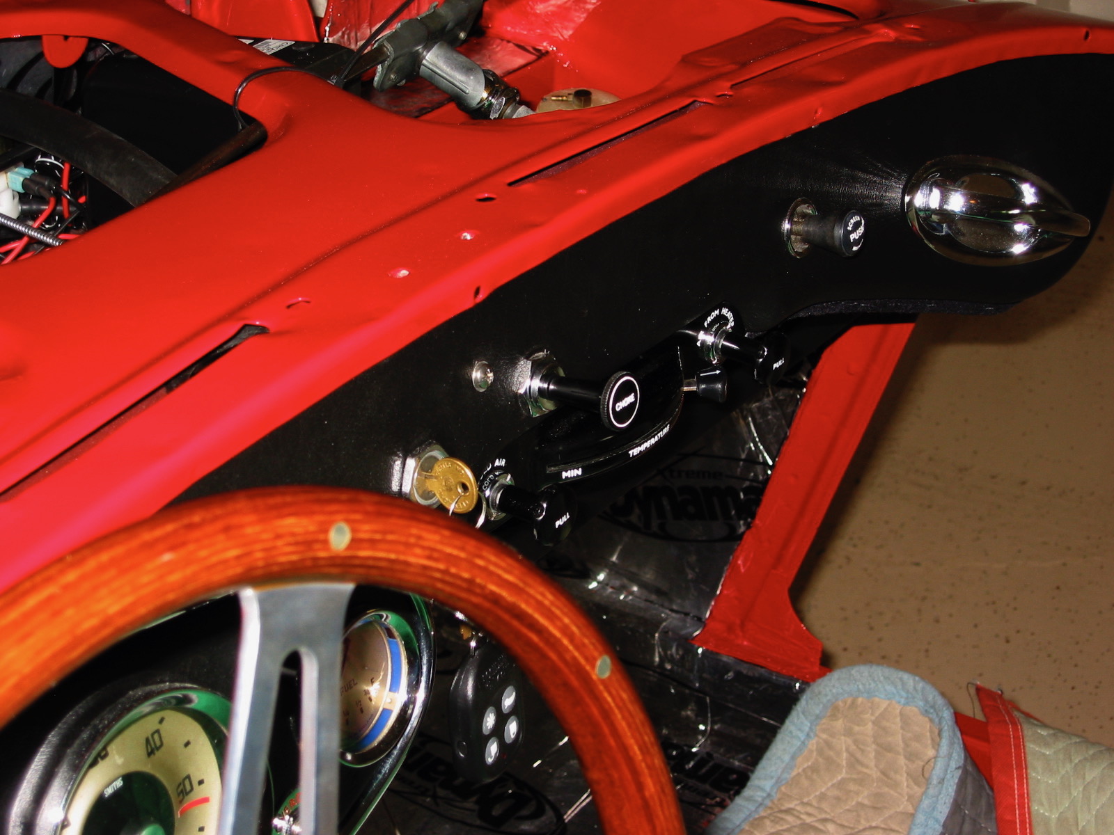
Cooling
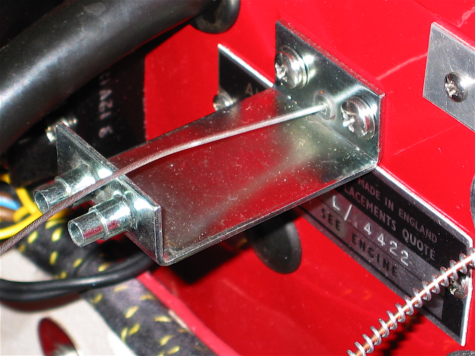
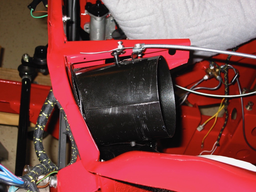
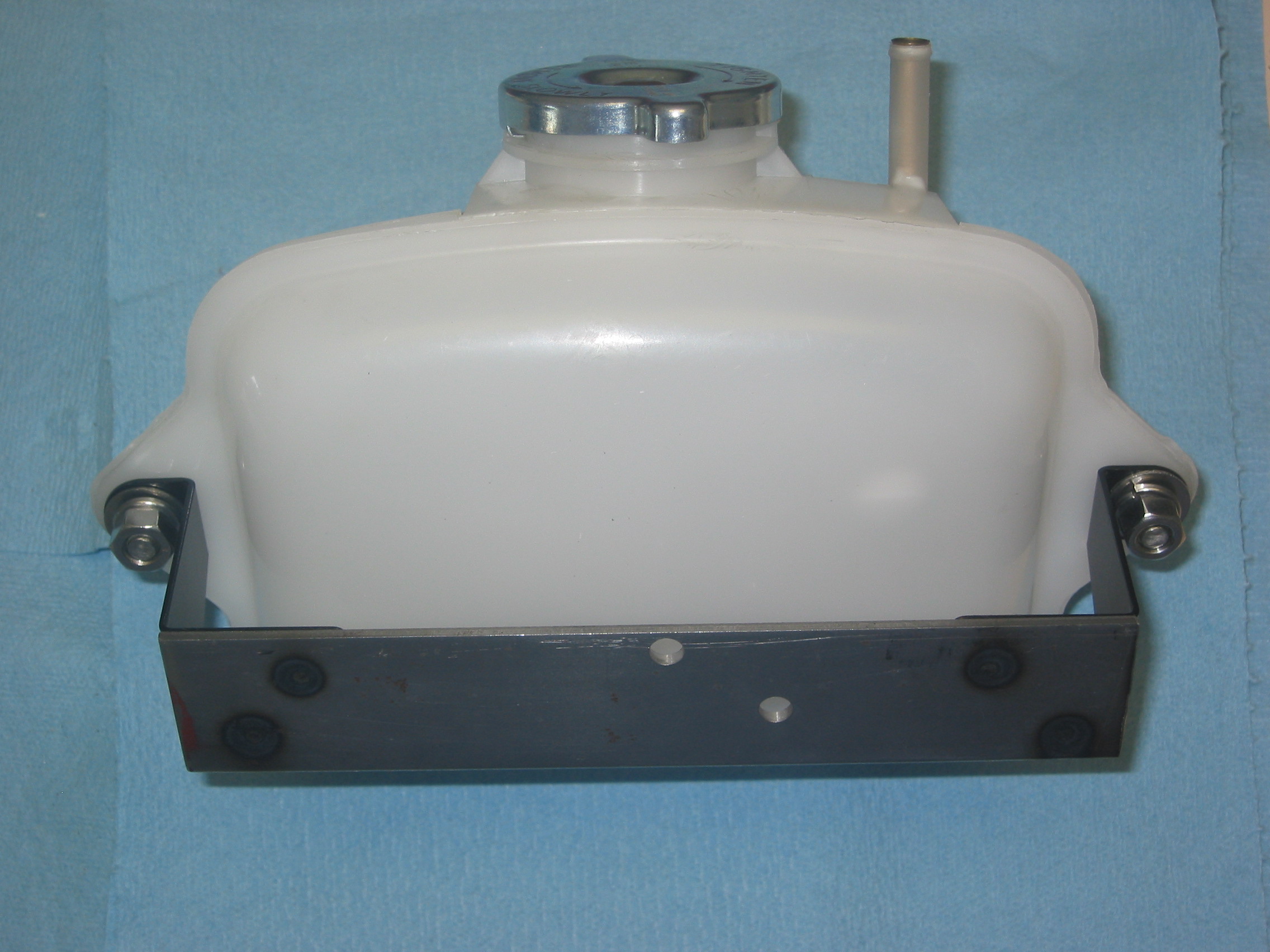
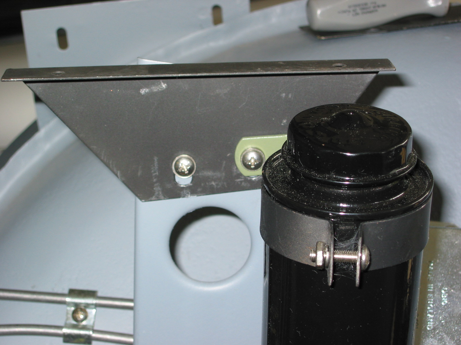
Cooling Recovery Tank – Began the installation of the radiator expansion tank from Cape International. However, I decided to wait to determine the final location until after the motor is installed. I don’t want to inhibit access to distributor or oil filter.
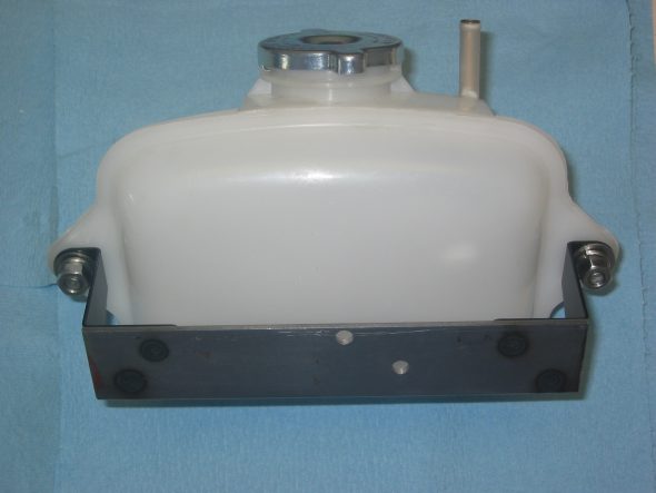
Coolant Recovery Tank with custom Bracket
Brakes
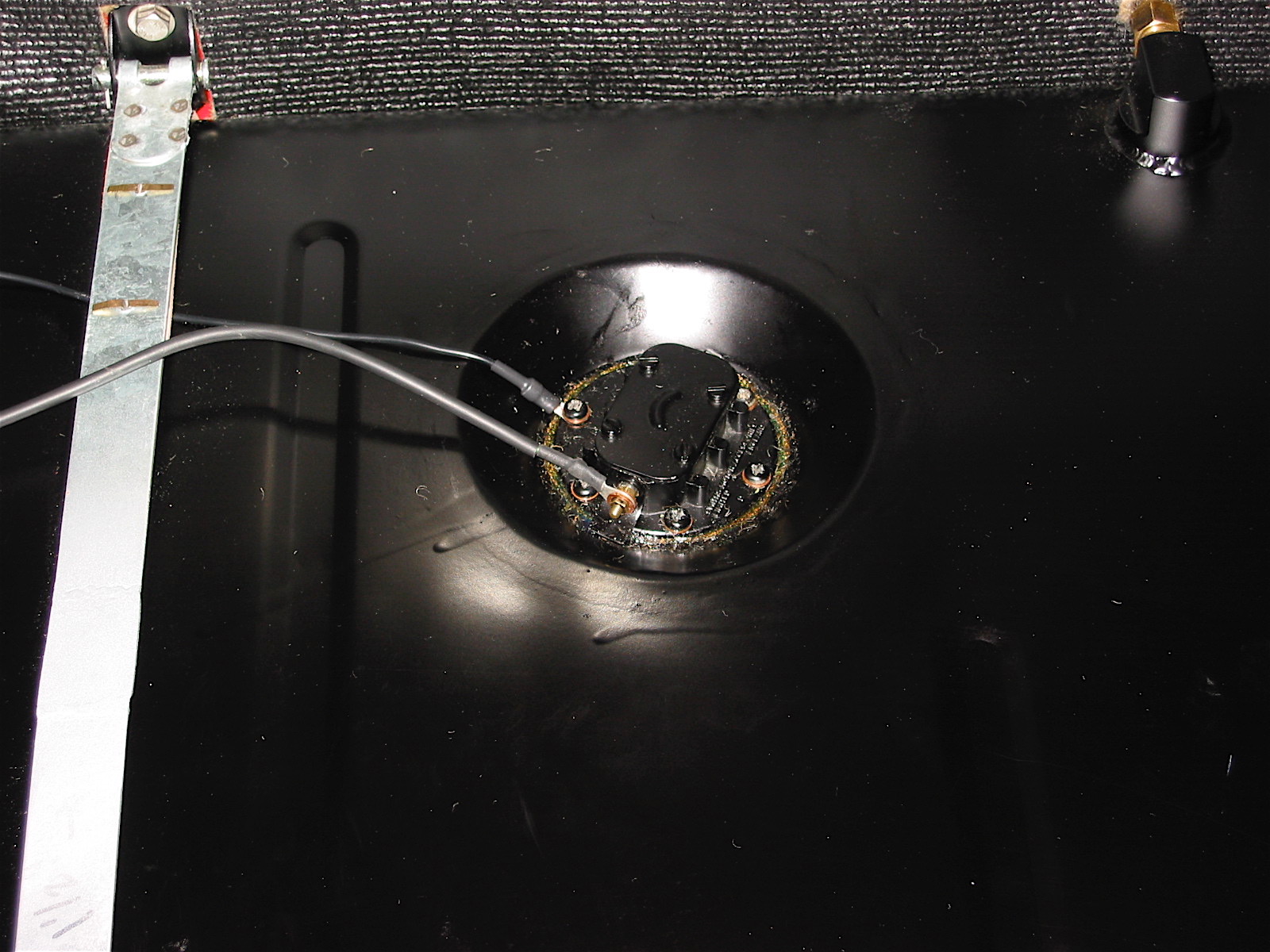
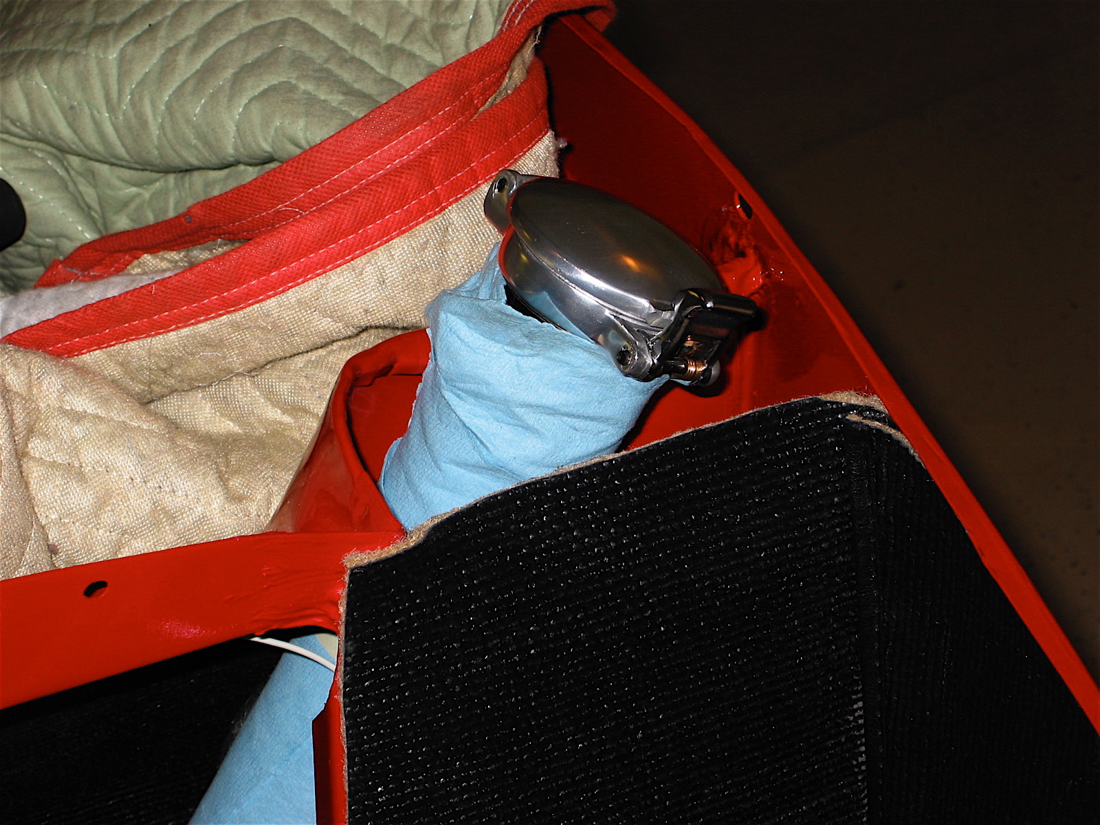
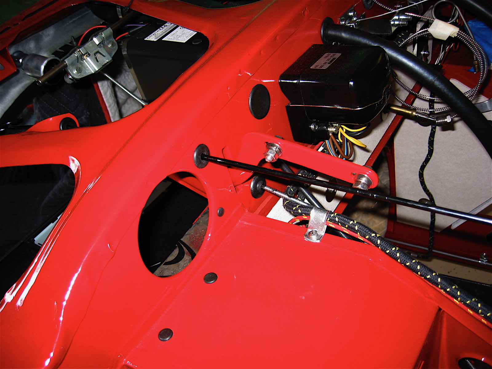
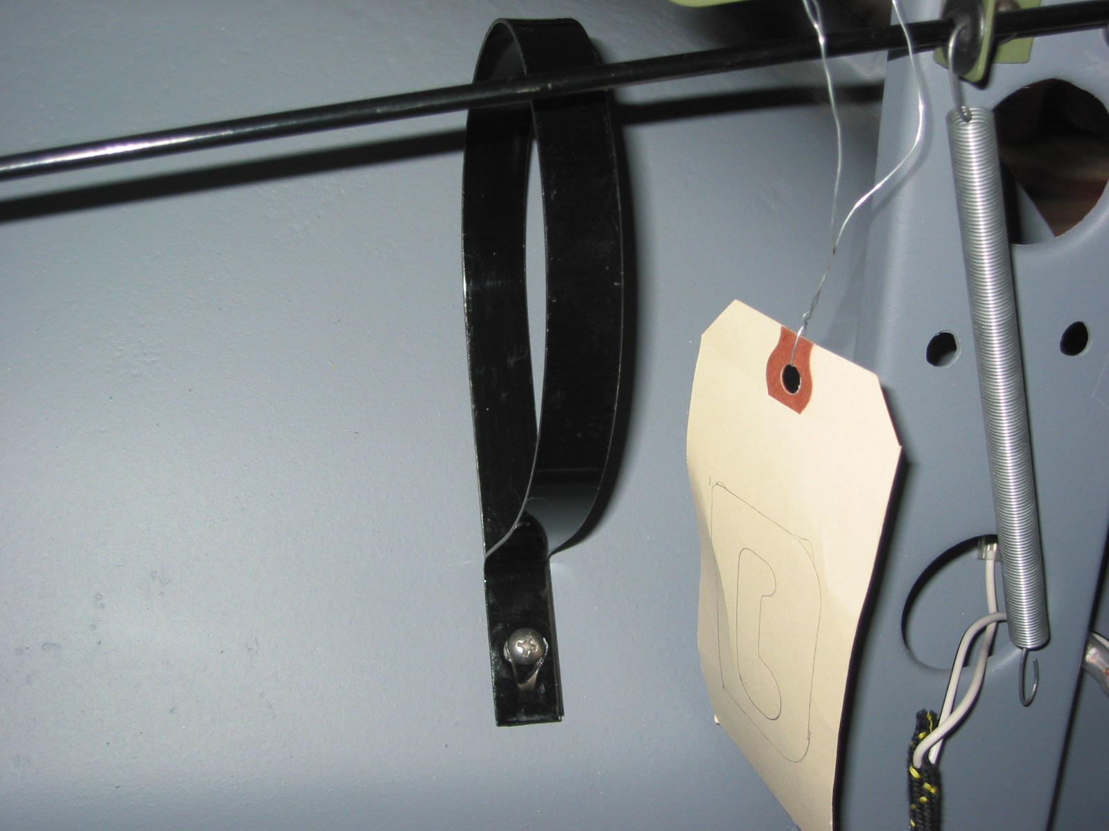
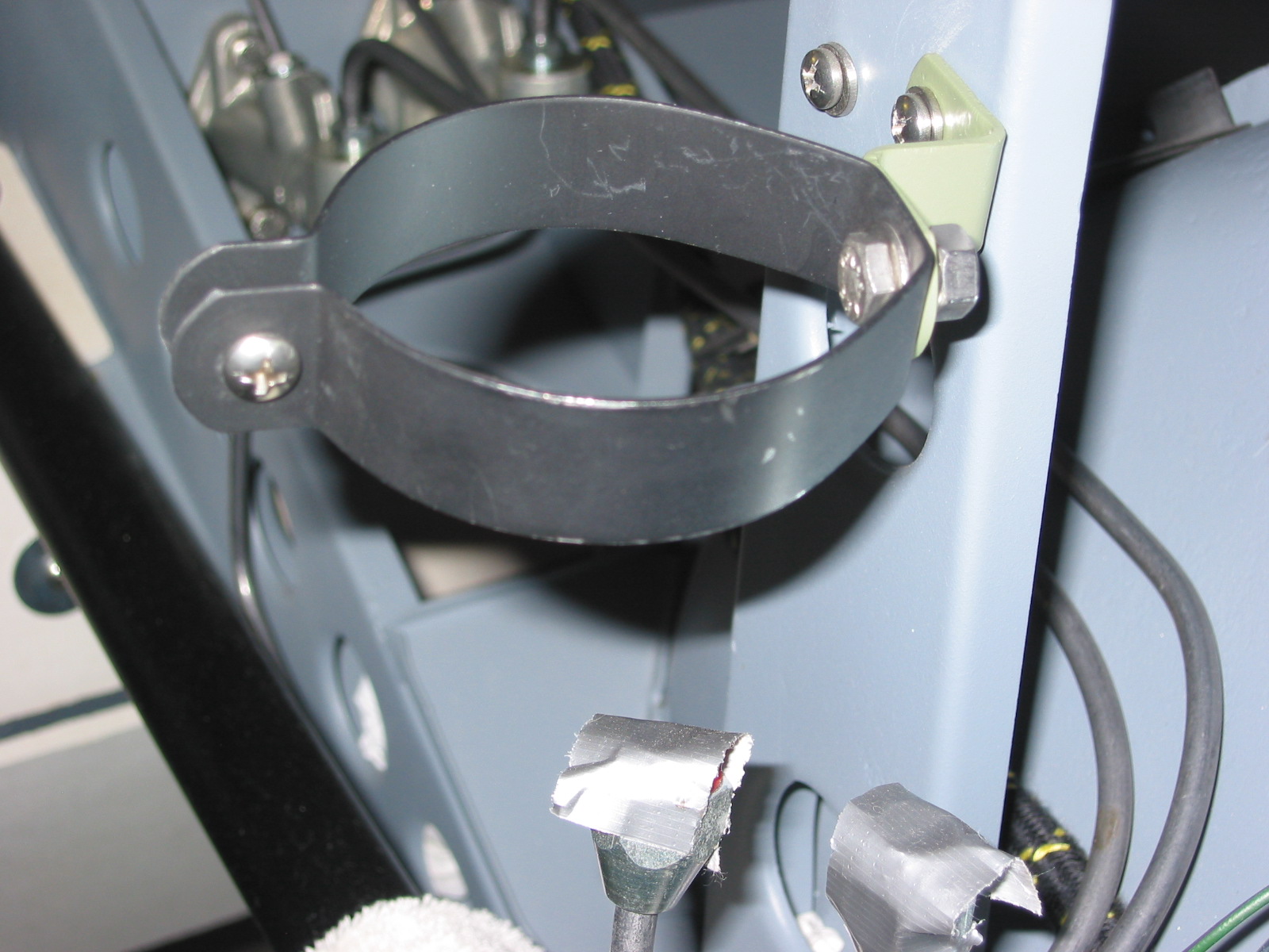
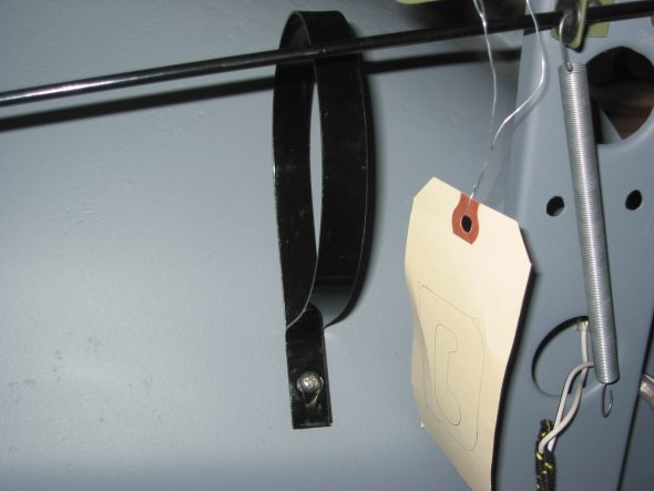
Brake Fluid Reservoir – Installed new brake fluid reservoir and will need to put thread sealer on fittings for final assembly.
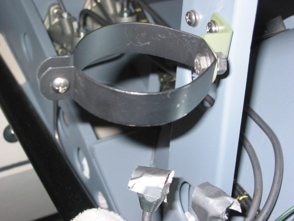
Brake reservoir clip 2

Brake Reservoir Mounted
April 17 , 2004
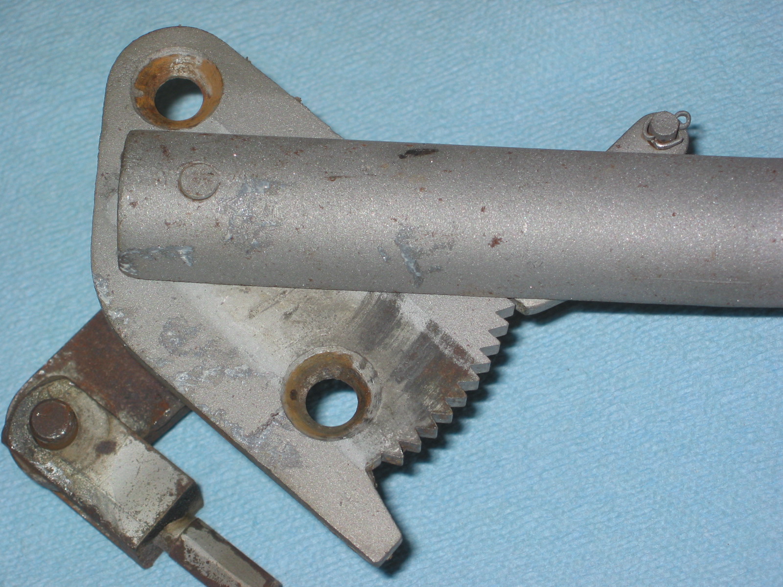
Handbrake Restoration
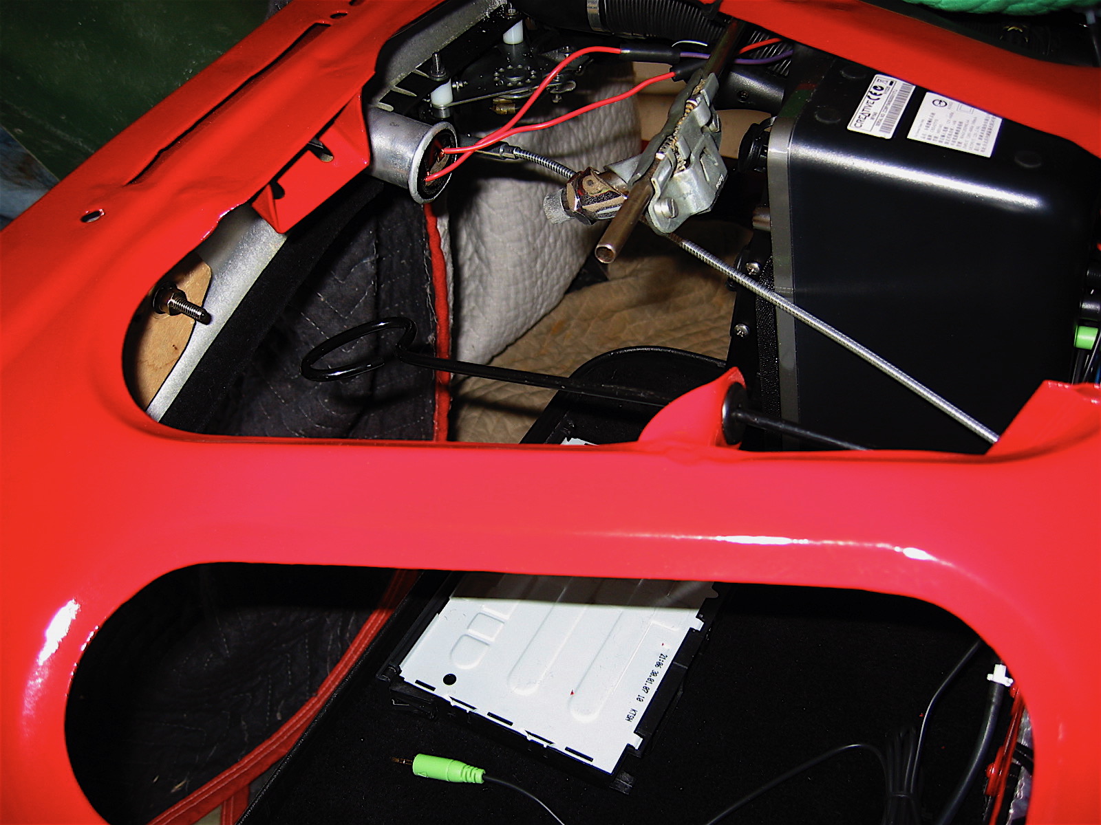
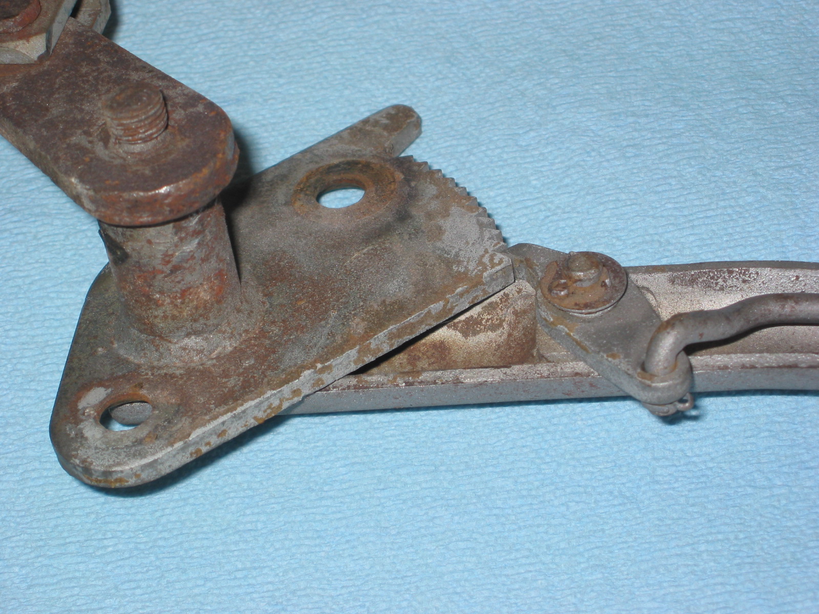
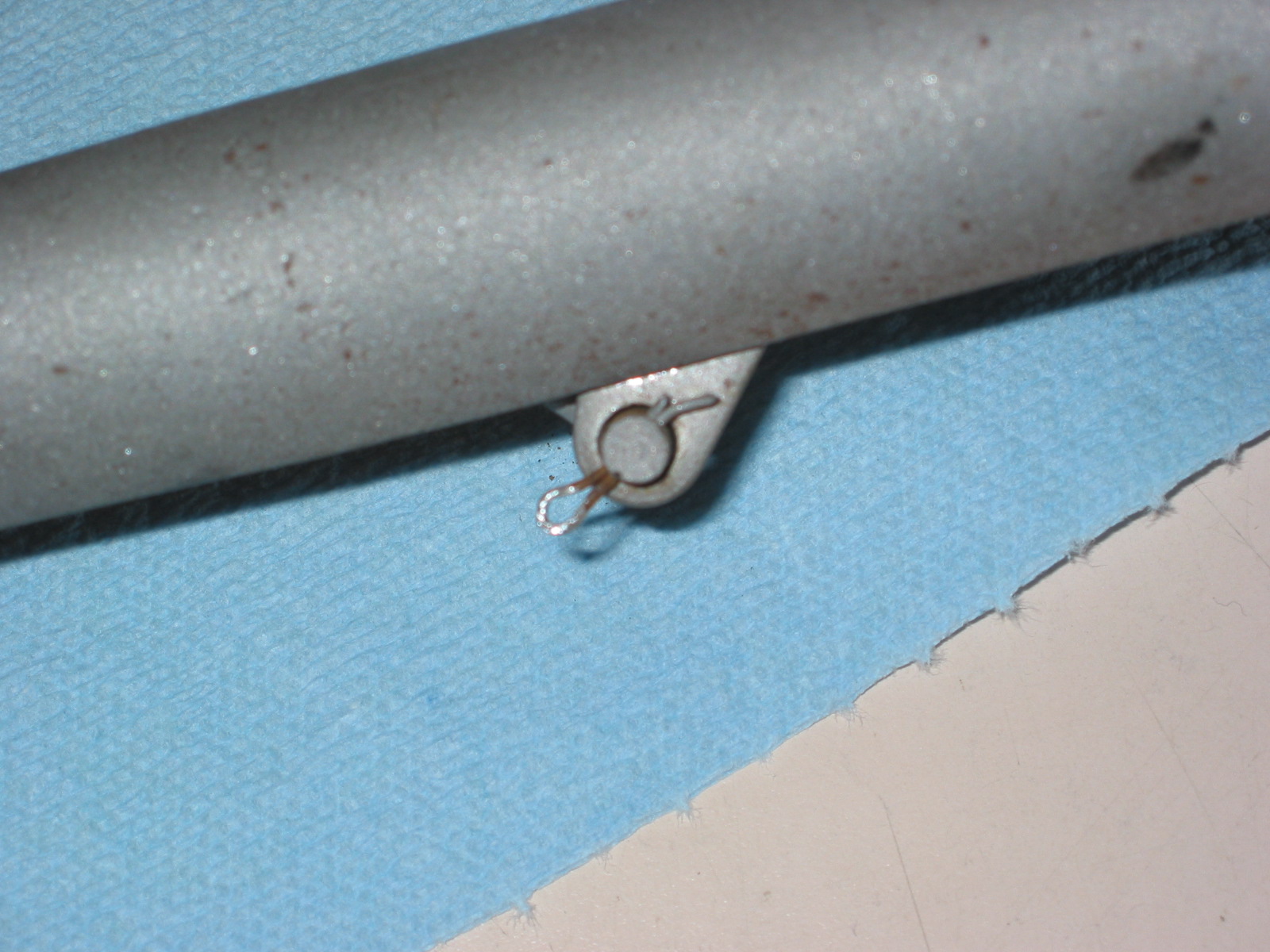
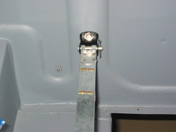
I decided to restore the original handbrake rather than purchasing a new one. This will require rechroming several pieces. Removed small split pin securing the rod to the lever. Then removed the small split pin and washer from the lever holding the pawl.

Handbrake Assembly 1

Handbrake Pawl split pin
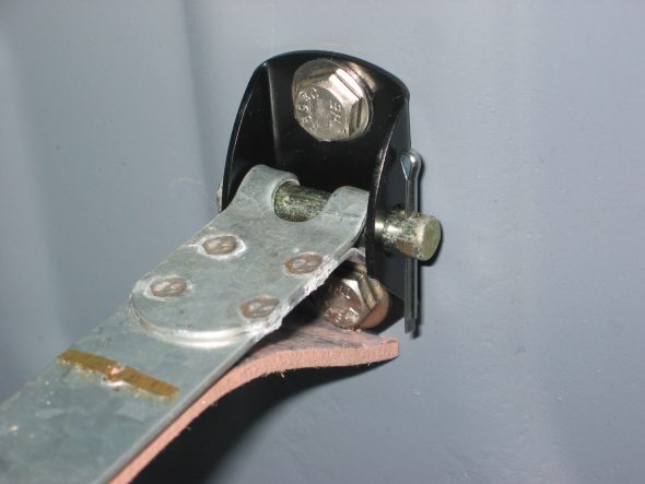
Disconnected the rod from the pawl and lifted the pawl off. Removed bracket with a hole and a rectangular opening for a key by heating with a torch and knocking out the piece. (Note orientation for reassembly). Hammered ratchet plate off of the mounting shaft to handle. There is a thin shim washer on the handle post before the ratchet plate is inserted on the shaft. The handle, pawl and ratchet plate will be chromed. The bracket and two spacers were painted black.
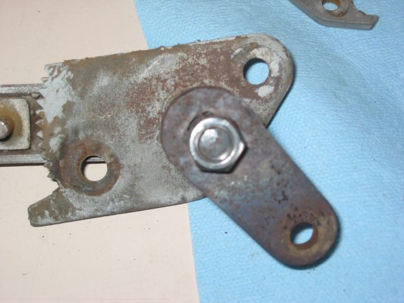
Handbrake connecting plate

Handbrake Assembly 1 2
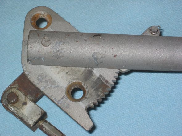
Handbrake Assembly 2