Rear Axle
All of the MK2s are fitted with a 4.HA Salisbury axle. The rear axle assembly is a semi-floating type with shim adjustment for all bearings and meshing of the hypoid drive gear and pinion matched assembly. The axle shafts are splined at the inner ends, which engage splines in the differential side gears, while the outer ends have tapers and keys to fit the rear wheel hubs. The hubs are supported by taper roller bearings pressed on the axle shafts and located in the end of the axle tubes. A cover on the rear of the gear carrier allows inspection without dismantling the axle.
Additional information about the axle installation and its related components in the rear suspension can be found in the “Rear Suspension” post at https://valvechatter.com/?p=3826.
Refurbishment
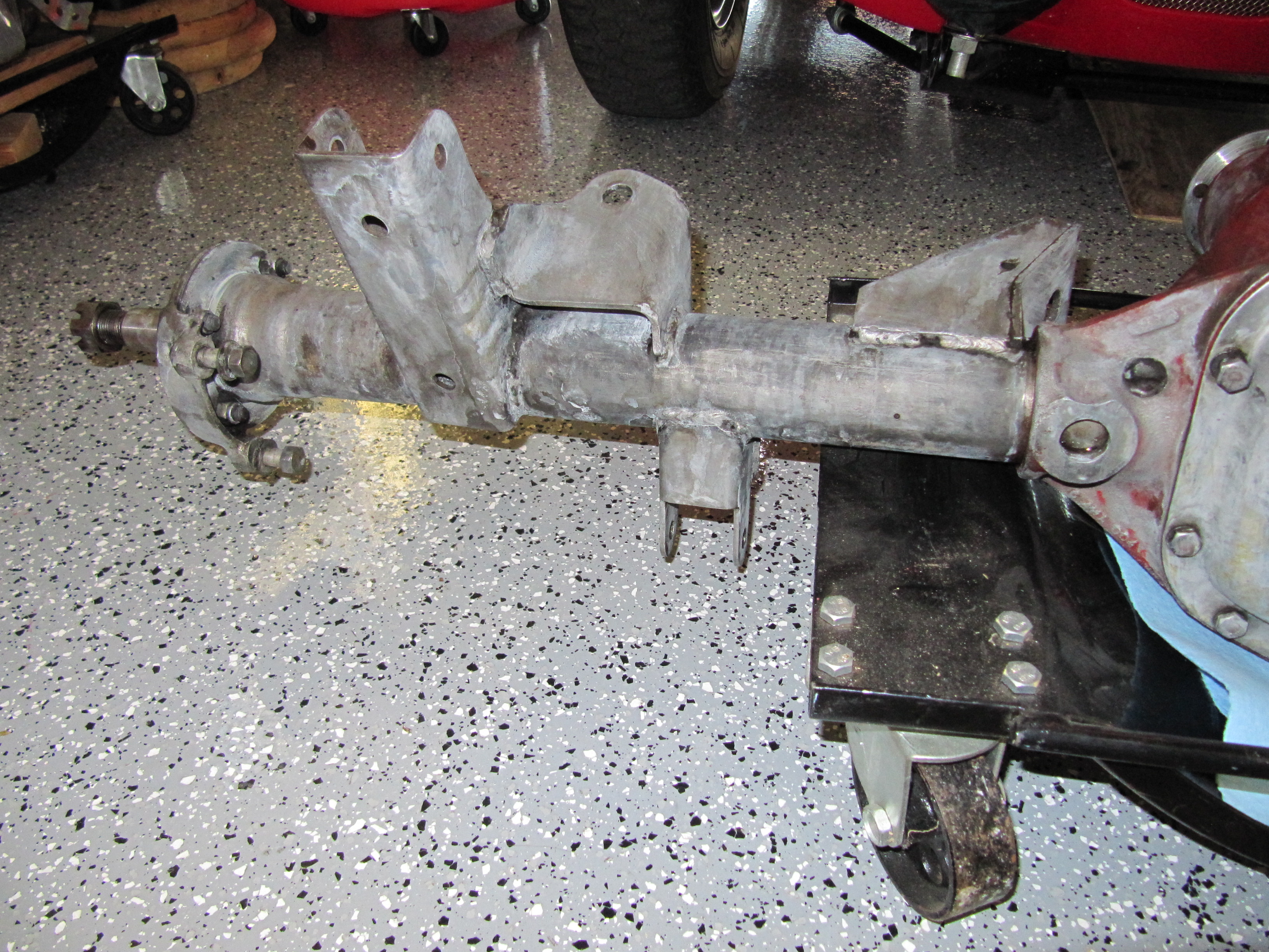
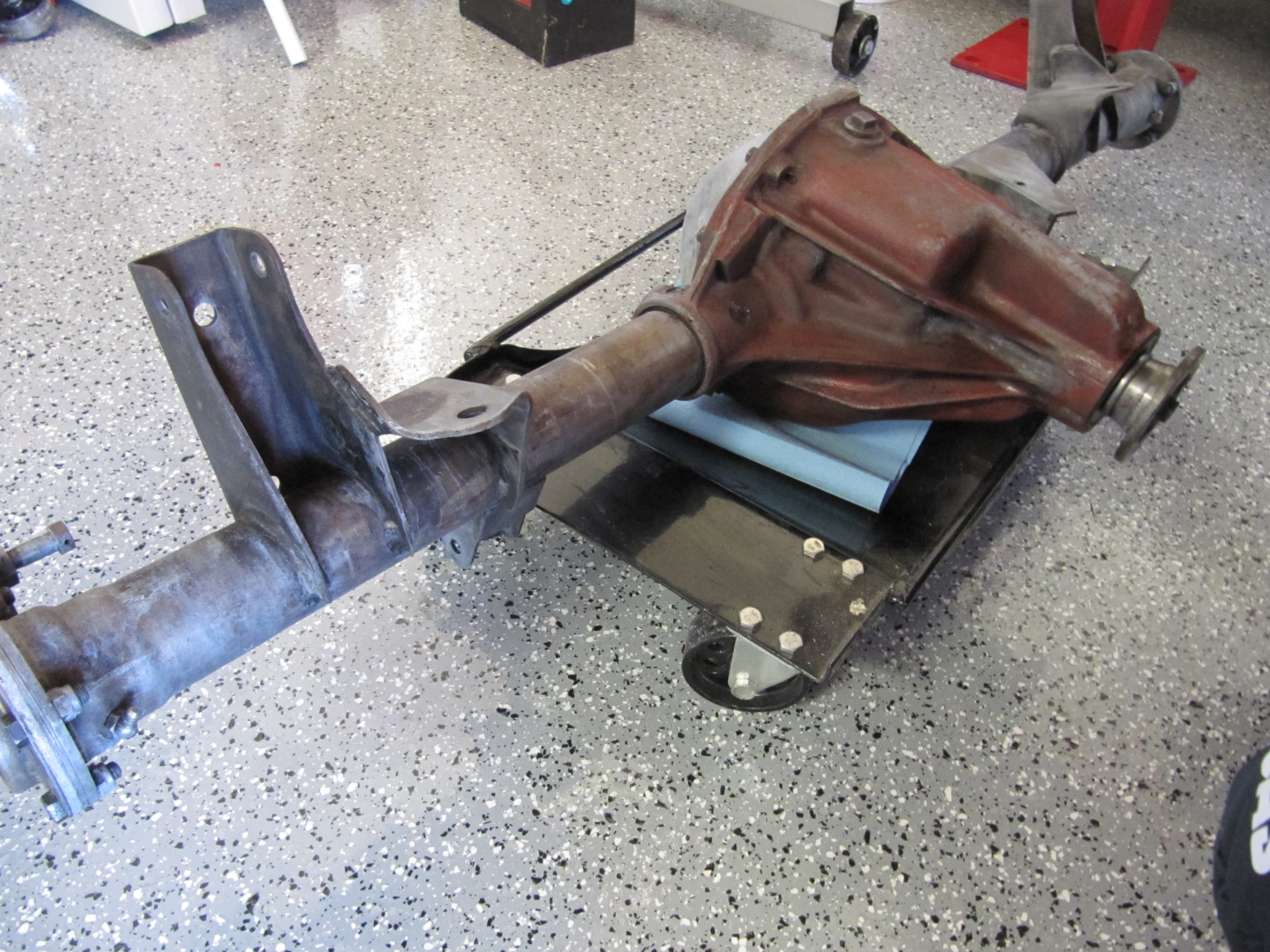
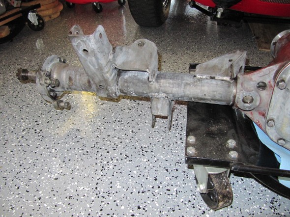
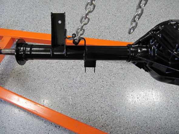
There is a big component stored in the garage that I have had trouble ignoring, but I have been putting off cleaning and refurbishing the rear axle for sometime. Perhaps it was Thanksgiving or the approaching holiday season, I don’t know, but I got motivated to start work on the axle. The axle images are sans the rear hubs. A description of the removal of the rear hubs is available in the disassembly section of posts, Entry 39 .
For starters, I took advantage of having the lift in the garage and used it to make it easy to access the axle for cleaning.

Rear Axle on Lift for Cleaning
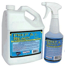
It was really just a matter of using the putty knife, cleanser, throttle cleaner, a wire brush and rags to remove the dirt and grime. After getting things as clean as possible I then used POR 15’s painting prep product called Prep & Ready. Prep & Ready is used to neutralize any rust and etch and clean bare metal to allow better adhesion of POR-15. Directions call for soaking the metal and keeping it wet for approximately fifteen minutes and then washing it away with water and then dry.
Prep & Ready
Axle Degreased

Axle Degreased

Axle Degreased with Prep & Ready
The differential casing on my axle had very little (if any) black paint and so I wondered if it should actually be painted red. I did a little research and this is what Rob Reilly contributed on the Saloon-Lovers email list:
In the build process, after the cast iron center pumpkin was shaken out of the sand mold and shot blasted, it was dunked in Glyptol, usually orange or red though Glyptol comes in other colors. This is to seal in the microscopic sand particles remaining in the boundary layer at the surface of the cast iron. Same as XK engine blocks and Moss gearbox main housings. It was very dry in the foundry and the Glyptol stuck very well. Then it went to the machine shop, where the machining work was done on it, which takes off the boundary layer. It is not necessary to repaint it on these machined surfaces. Then the axle tubes were pressed in and welded through plug holes in the casting. Then the parts were assembled into it. At this point it was very oily all over the outside of the diff. Then the whole thing was painted black without any primer, but they did not clean it very well first, if at all.
So after a few years the black flaked off, revealing the orange or red. If you look carefully as I did on mine, you may see black on the axle tube plug welds, because the welding burned away the red/orange and the oil, so the black stuck better there. Mine had small flecks of black remaining on the outside of the diff. I also saw only black on the outside of the rear cover, and nothing at all on the inside of this cover. It is not necessary to restore the Glyptol on the outside of the diff. It is only important on the inside.
Thanks to Rob, for providing the history on why the differential casing on my car was red/orange – they all were!
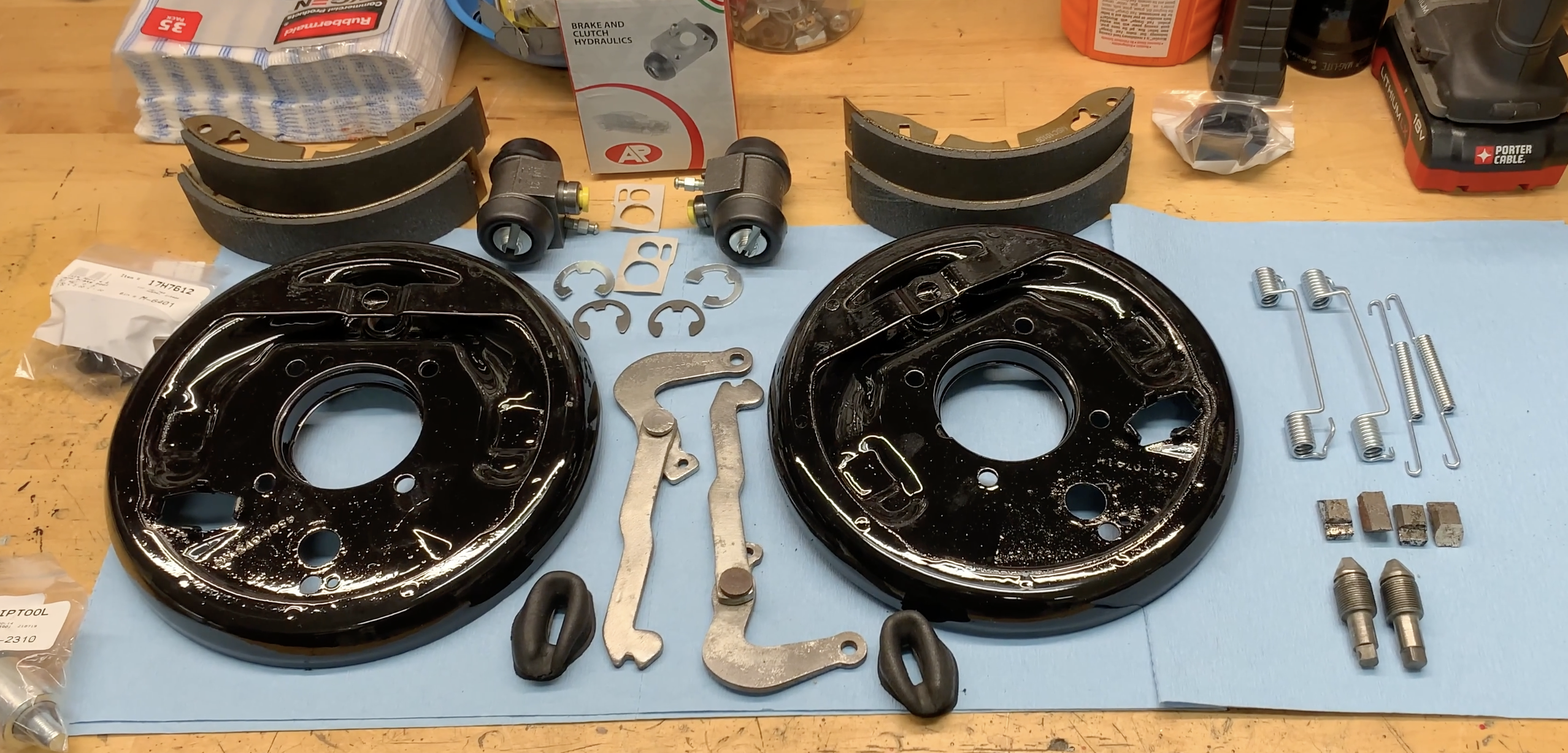
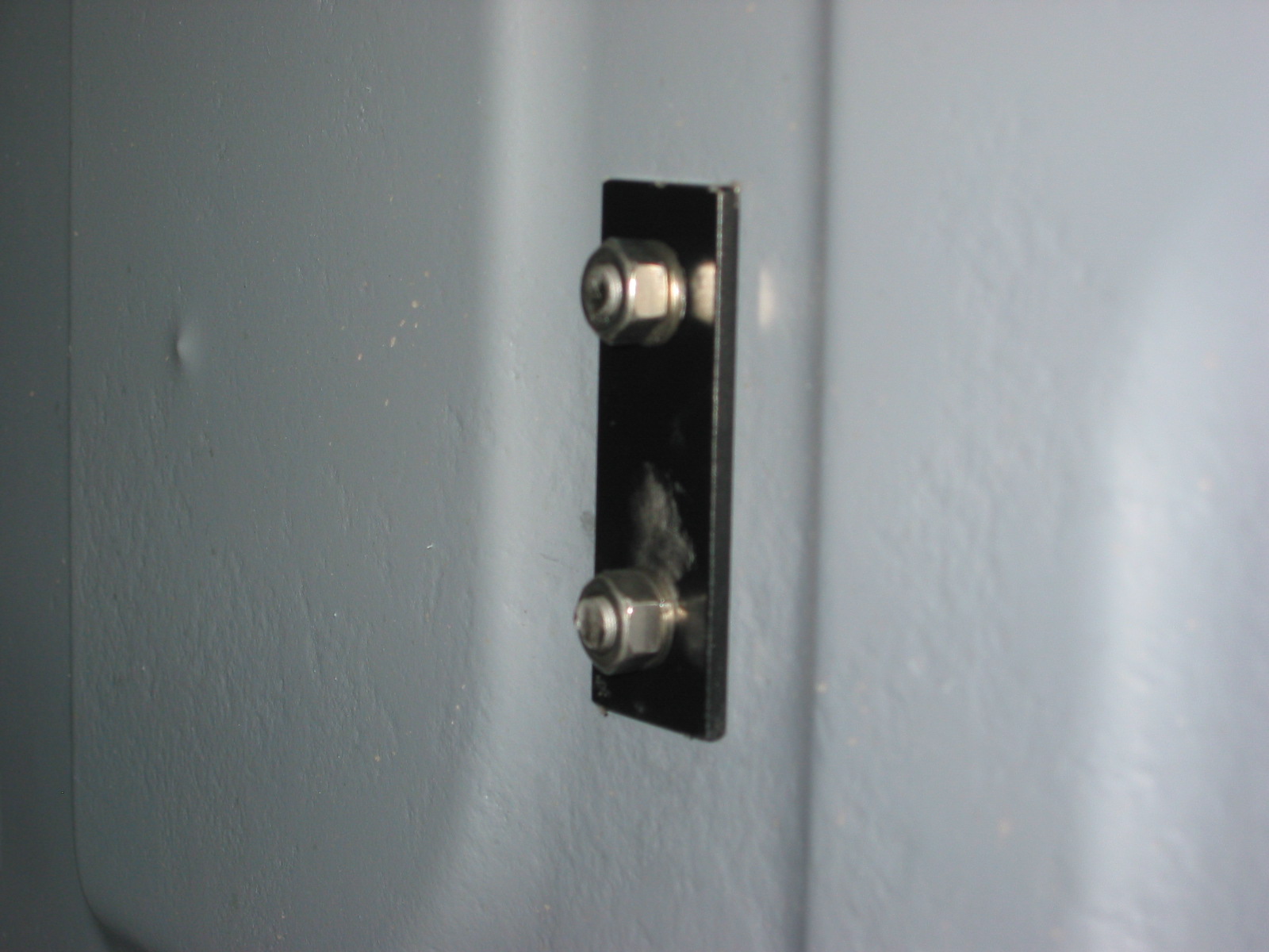
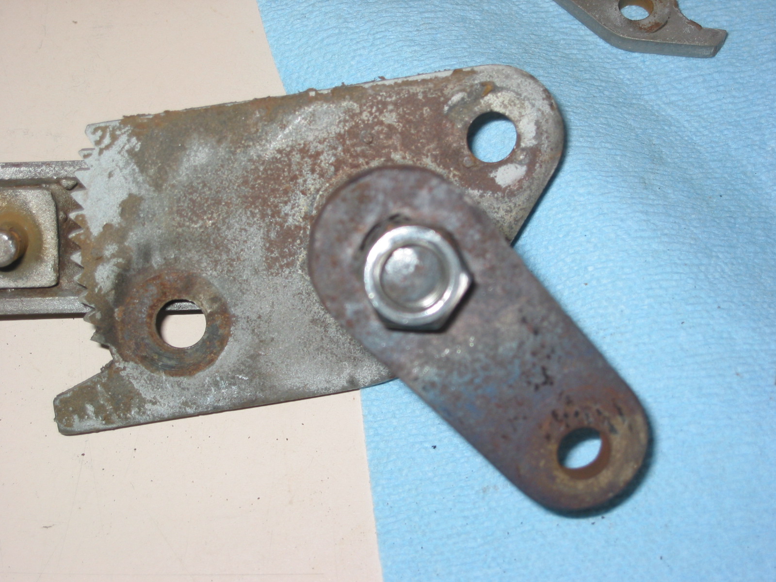
Brake Caliper Adaptor Plates
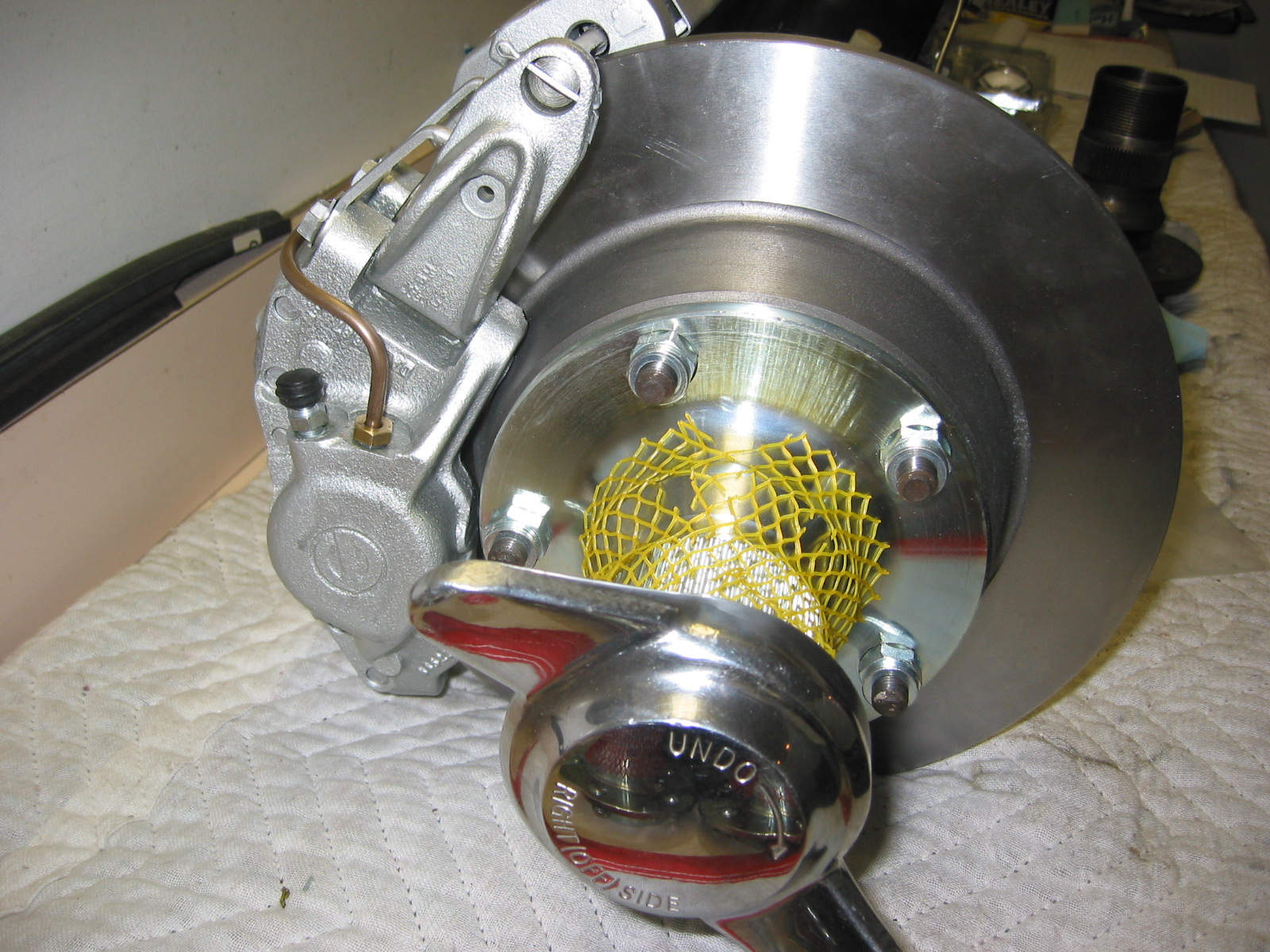
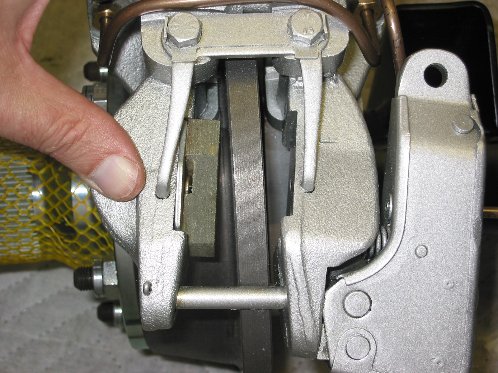
I then removed the LH and RH brake caliper adaptor plates. Each was secured to the axle with four 3/8″ – 24 x hex head bolts and nylock nuts, bolt heads to the outside. Each caliper was mounted to the adaptor plate with two 7/16″ -20 x 1 1/4″ hex head drilled bolts with split washers and safety wire. Shims were found on three of the caliper mounting bolts. They were noted for reassembly.

LH Adaptor Plate
LH Adaptor Plate
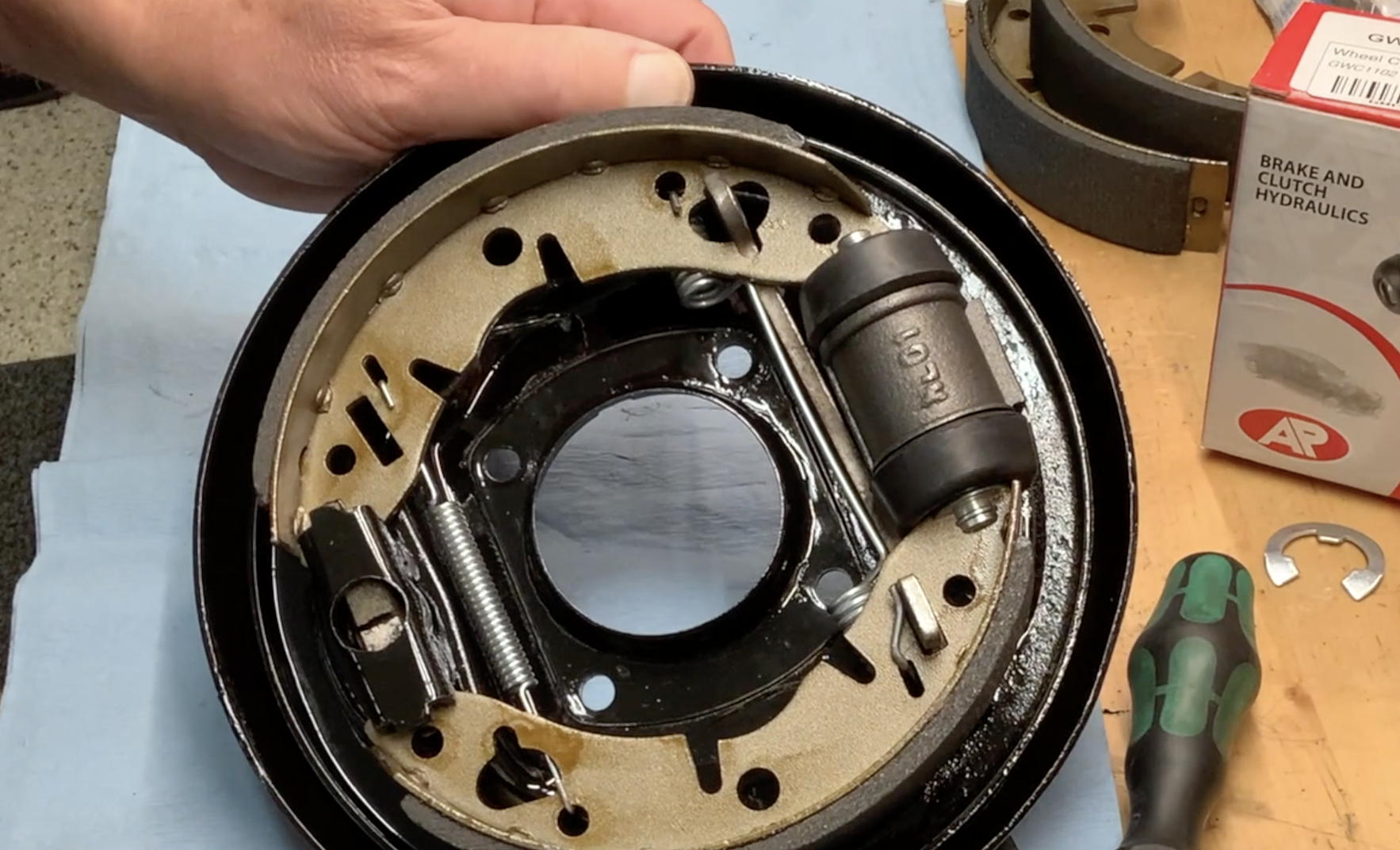
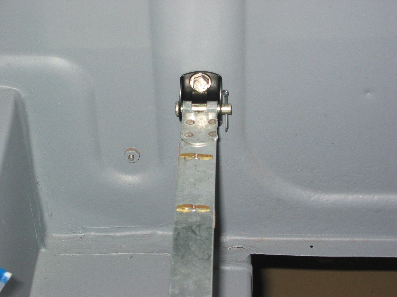
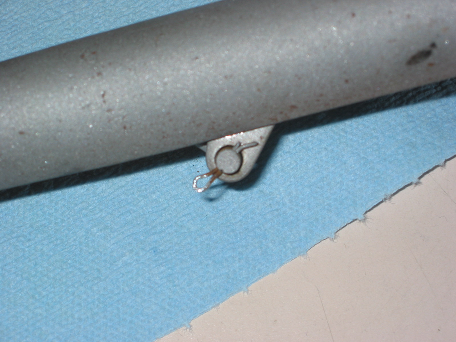
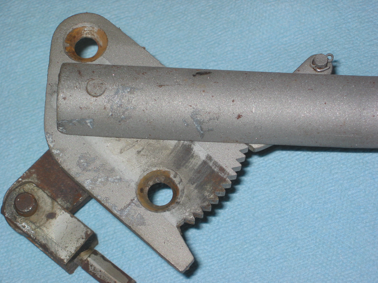
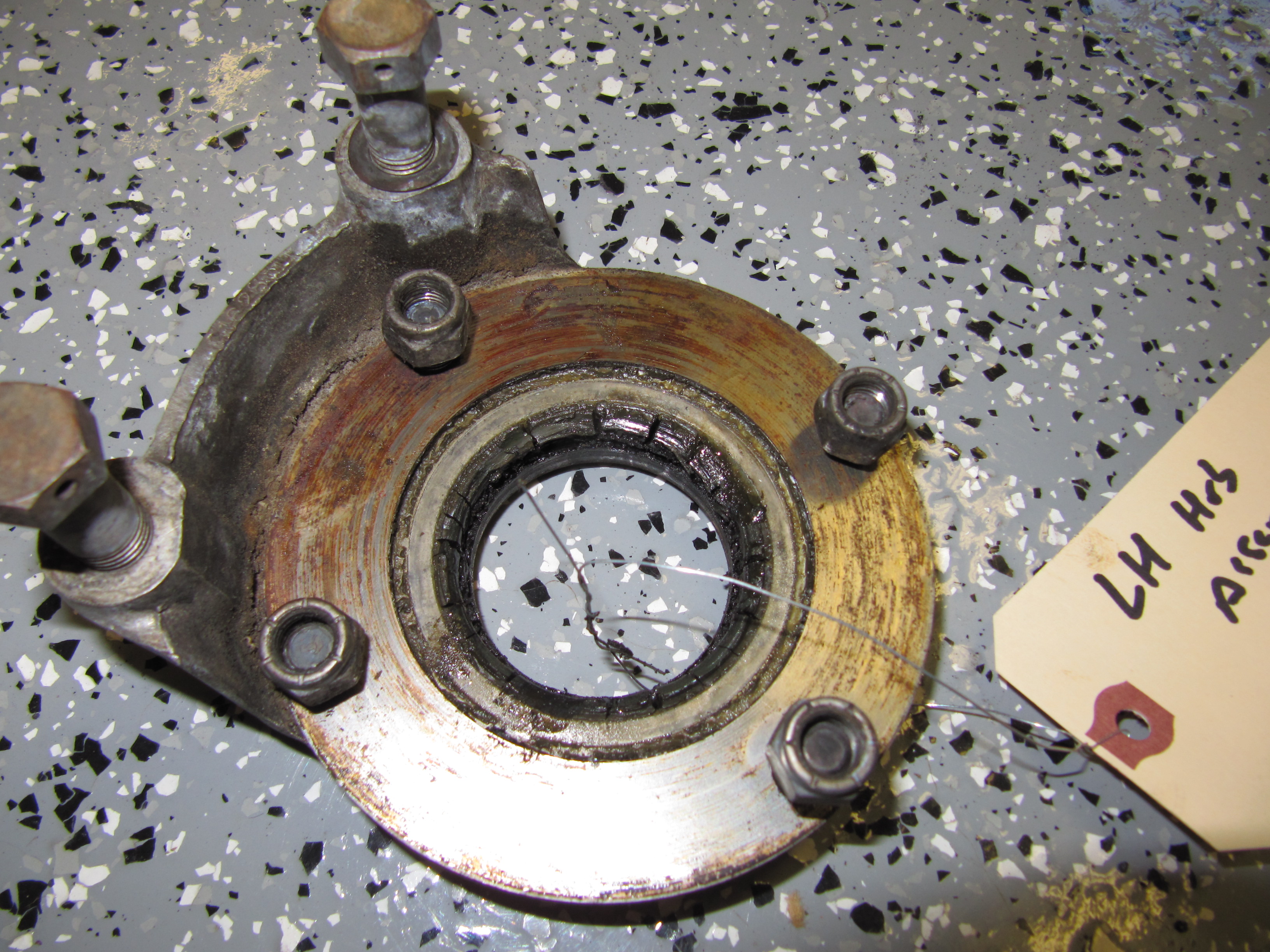
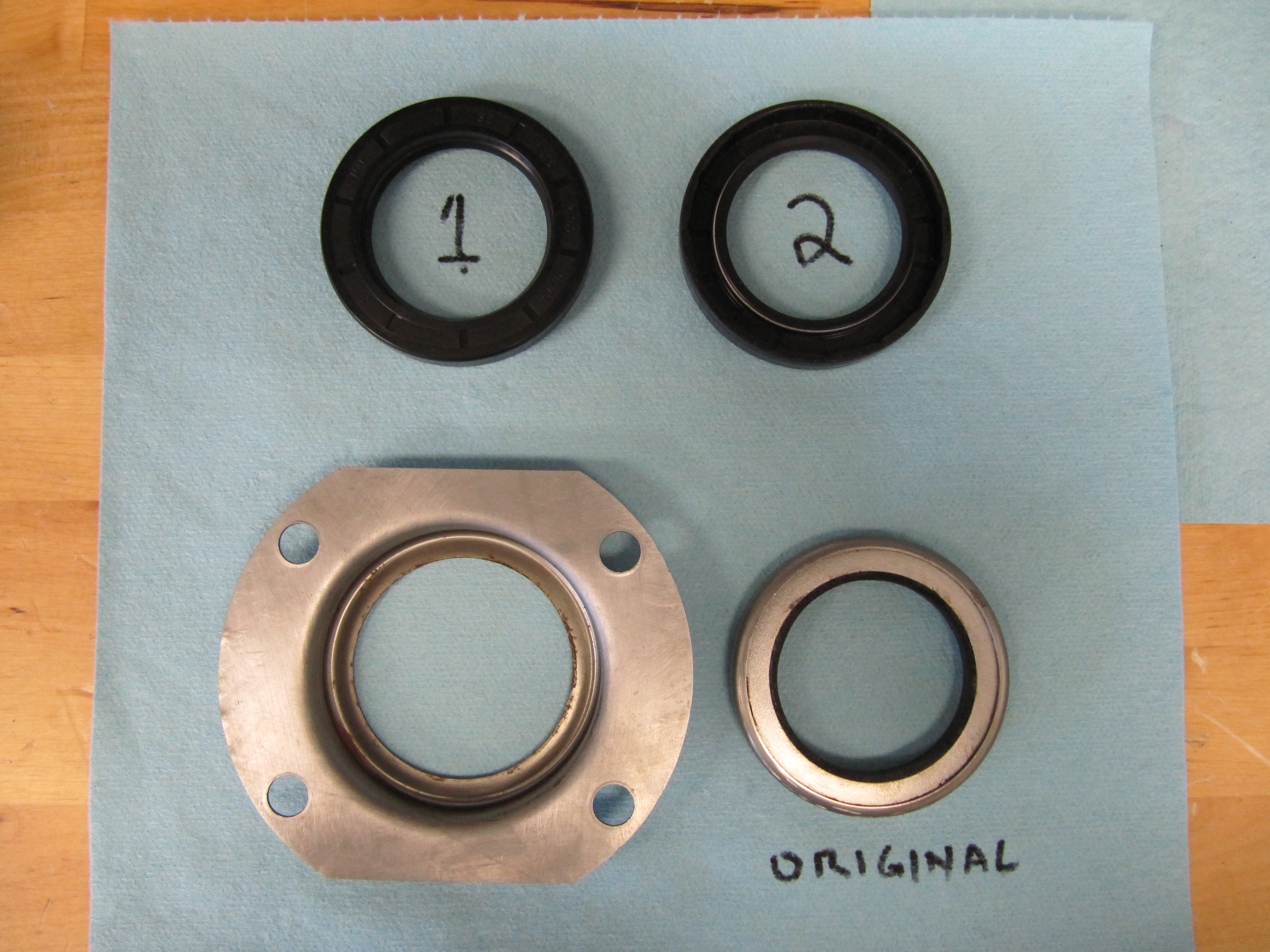
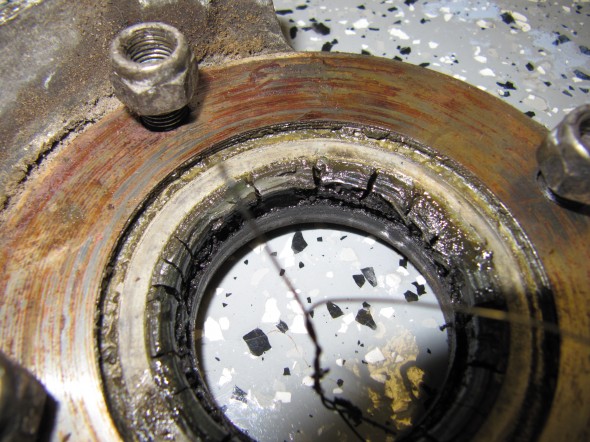
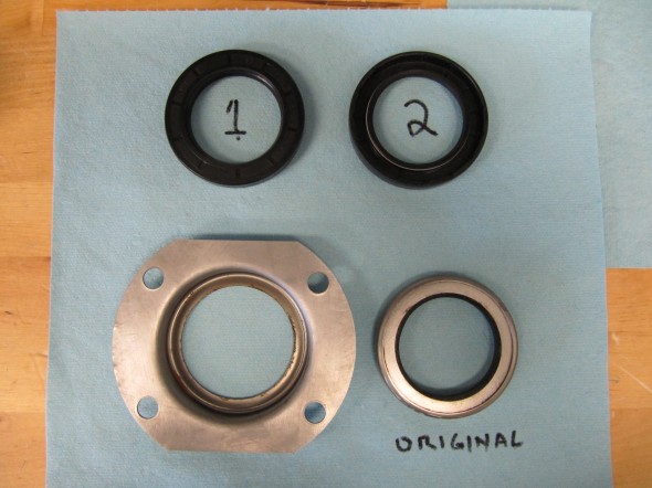
Oil Seal Assembly
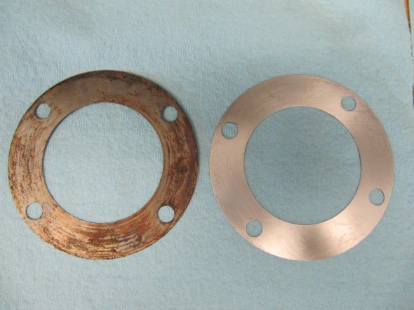
The next task was to remove the LH and RH oil seal assembly from the axle. The assembly consisted of: the oil seal on the end of the carrier tube axle shafts, the hub bearing adjusting shims, and a gasket. I was careful to record the number, location (LH or RH), and size of the shims, and I will replace the bearings and gasket later.

RH Oil Seal Assembly
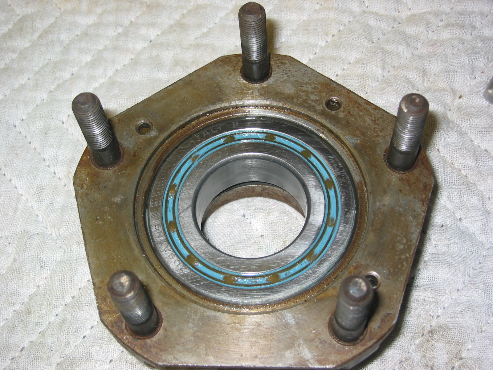
The image below shows the face of the timken bearing ( 14130-X-14276) 7HA-025).

RH Axle Shaft with Bearing & Seal
After cleaning up around the removed adaptor plates, I then painted the axle tubes and casing with two brushed coats of glossy black POR-15 followed by one sprayed coat of gloss Blackcoat which is a permanent overcoating developed as a non-porous finish that as advertised will not crack or chip. Unlike the POR-15 it is not harmed by exposure to sunlight.

Rear Differential Carrier Cover
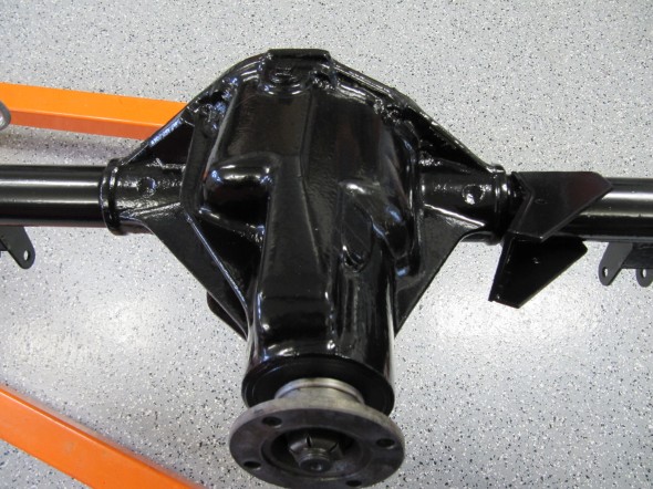
Rear Diff Bottom
Painted Axle
Painted Axle

Newly Painted Rear Axle
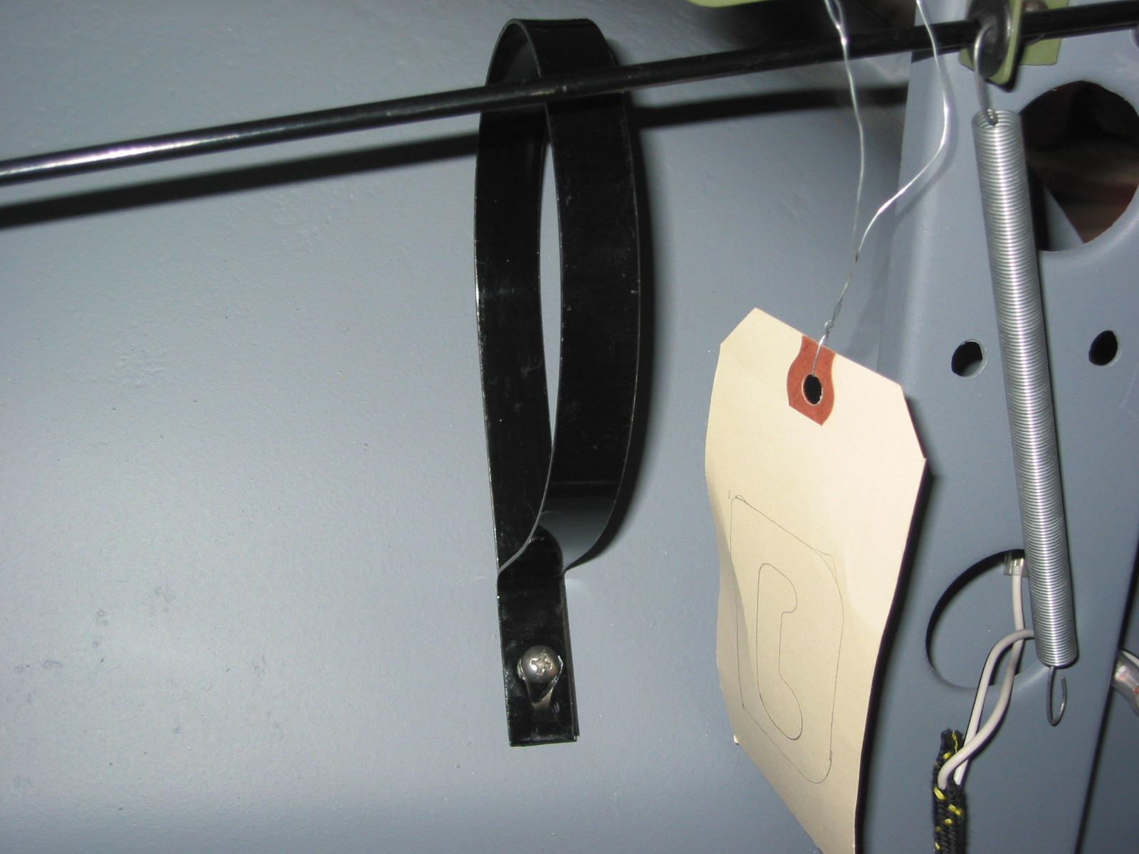
Rear Differential Identification Tags
Two stamped tags were located on the upper and lower mounting bolts for the carrier cover. One was stamped 49/13 which is the final drive gear ratio or 3.77. This ratio was the gear set fitted for overdrive equipped cars. I am told that the other which was stamped with “BP-L” signifies that the differential is a Powr-Lok Limited Slip.

Differential ID Tags
Bearings and Seals
When I purchased the MK2, I drove the car for five-six miles. I did not hear anything unusual from the rear end, and the differential does not appear to be leaking from the pinion. I will replace the axle shaft/hub bearings and seals and gaskets along with new hubs, but upon the advice of others, I am going to leave everything else alone for the time being. I have taken off the carrier cover and visually inspected the crown and pinion surfaces with no apparent wear problems.
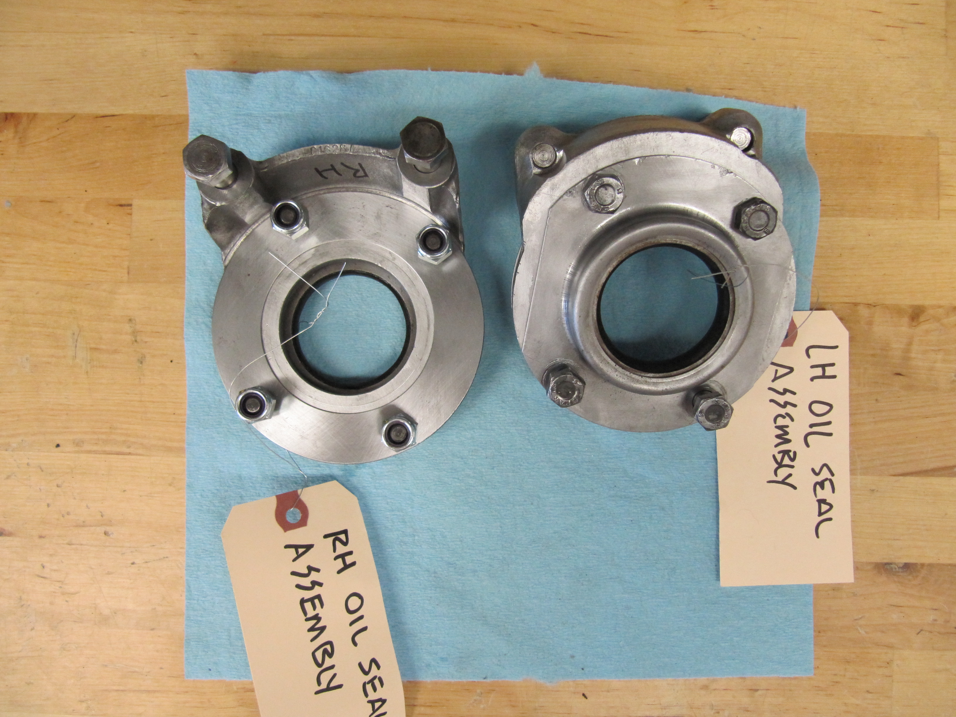
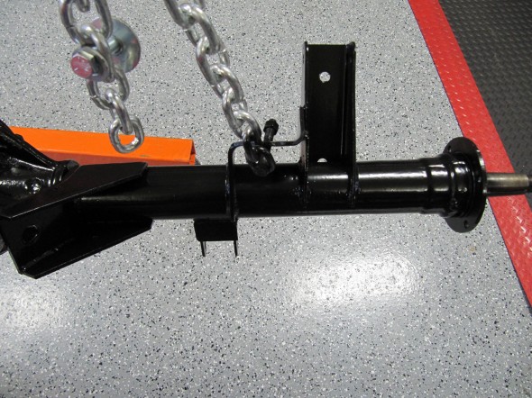
Oil Seal Assemblies and Brake Caliper Adaptors
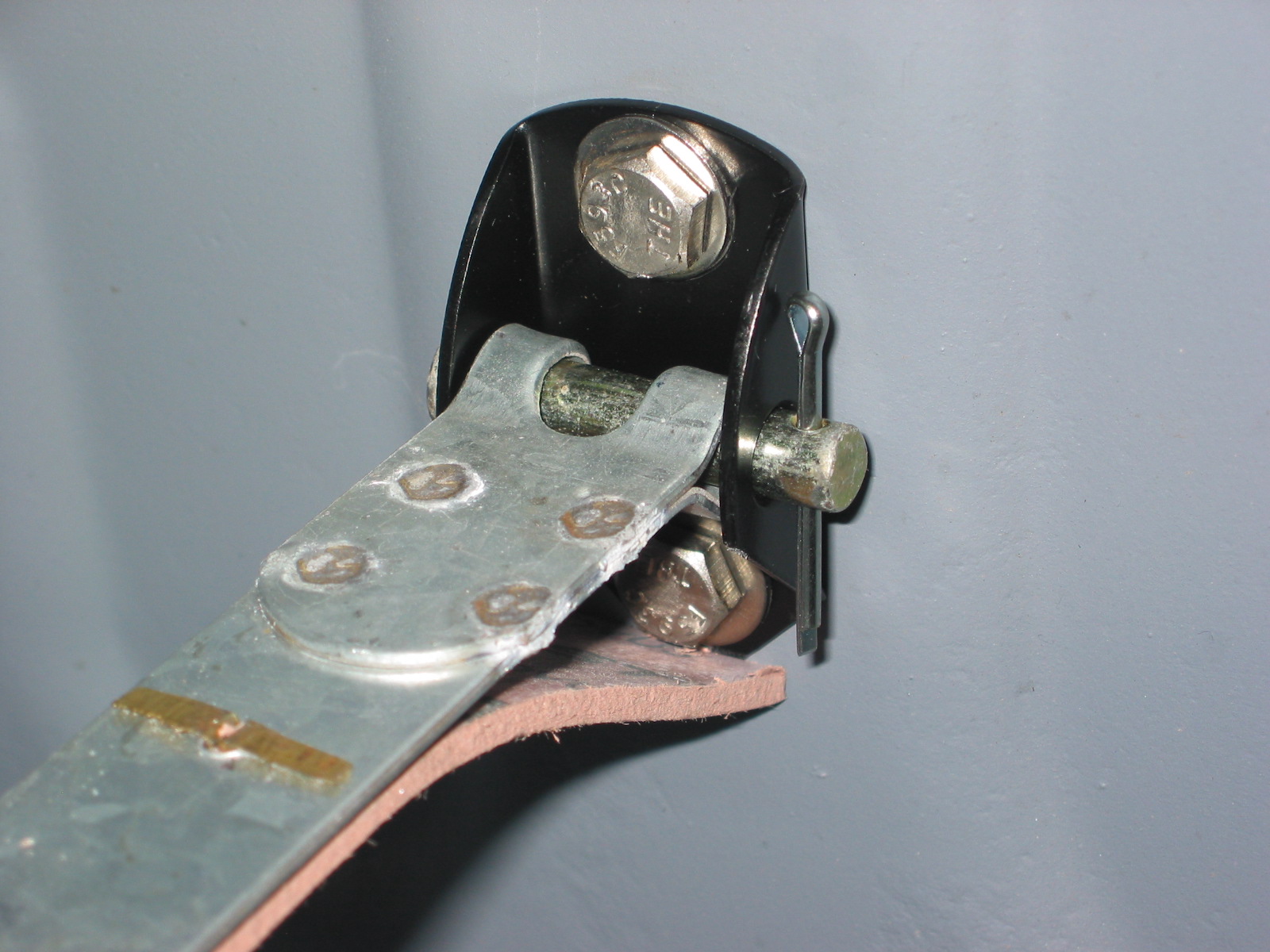
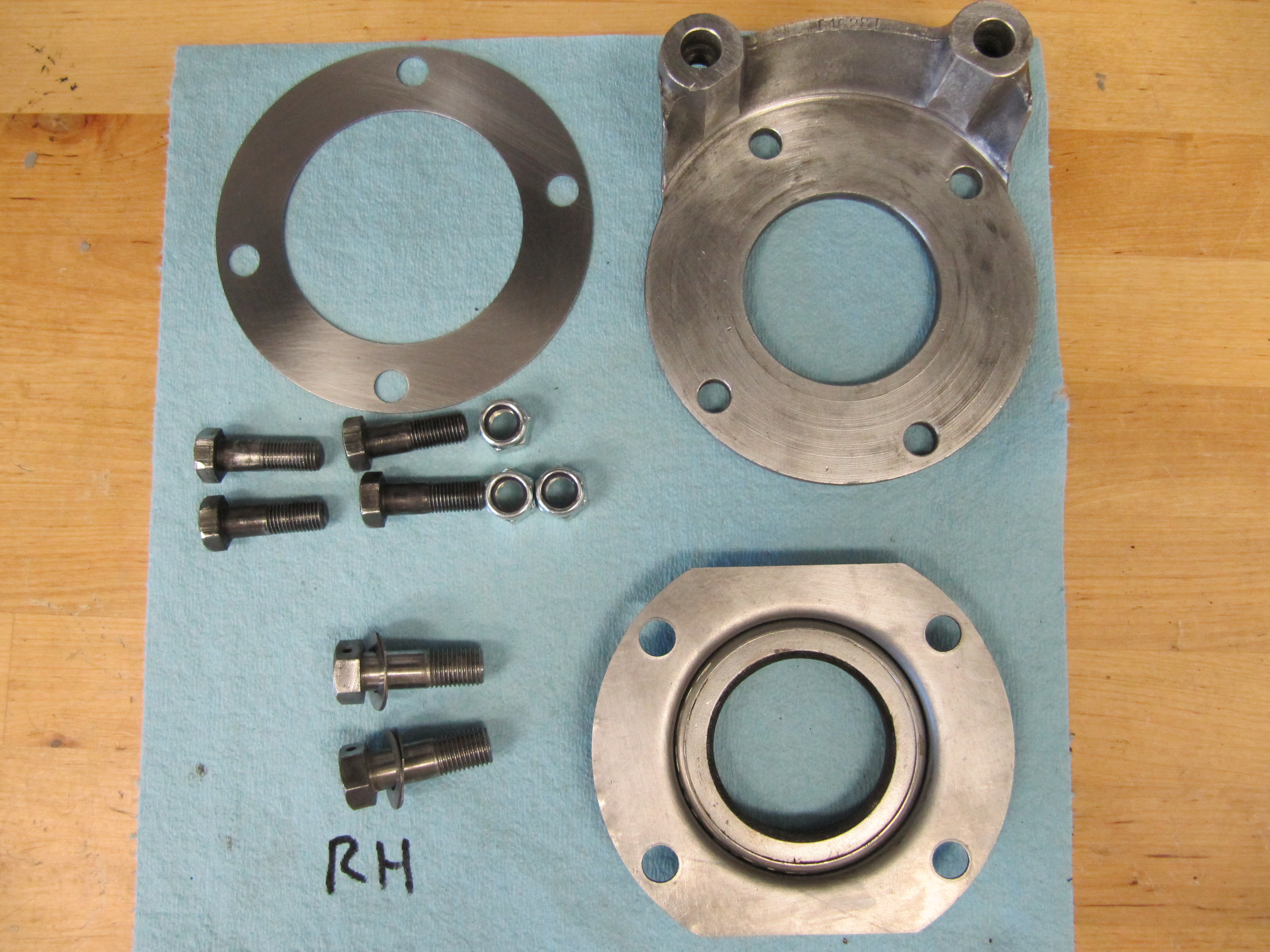
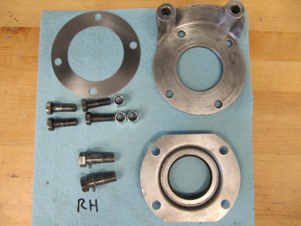
The final components of the ale to clean and reassemble were the LH and RH oil seal assemblies and brake caliper adaptors. The LH assembly had four shims (.o1″, .01″, .03″, and .03″) while the RH had only one shim (.03″). The assemblies were bolted to the axle ends with four 3/8″ -24 x 1 1/8″ hex head bolts and 3/8″ – 24 nylock nuts. Sandwiched between the oil seal assembly and the adaptor was a paper gasket. The original oil seal was a metal encased leather seal, while the new replacements are an improved rubber seal as shown in the images below.
The brake calipers were mounted to the adaptors with two 7/16″ -20 x 1 5/16″ drilled (for safety wire) hex head bolts with split washers. The RH adaptor had two .02″ shims on each bolt, while the LH side had no shims.
Shims
Oil Seals
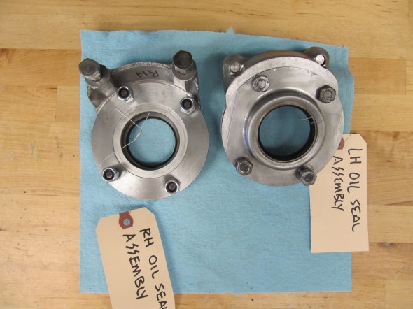
LH and RH Oil Seal Assemblies and Adaptors Cleaned
RH Oil Seal Assembly Components and Caliper Adaptor After
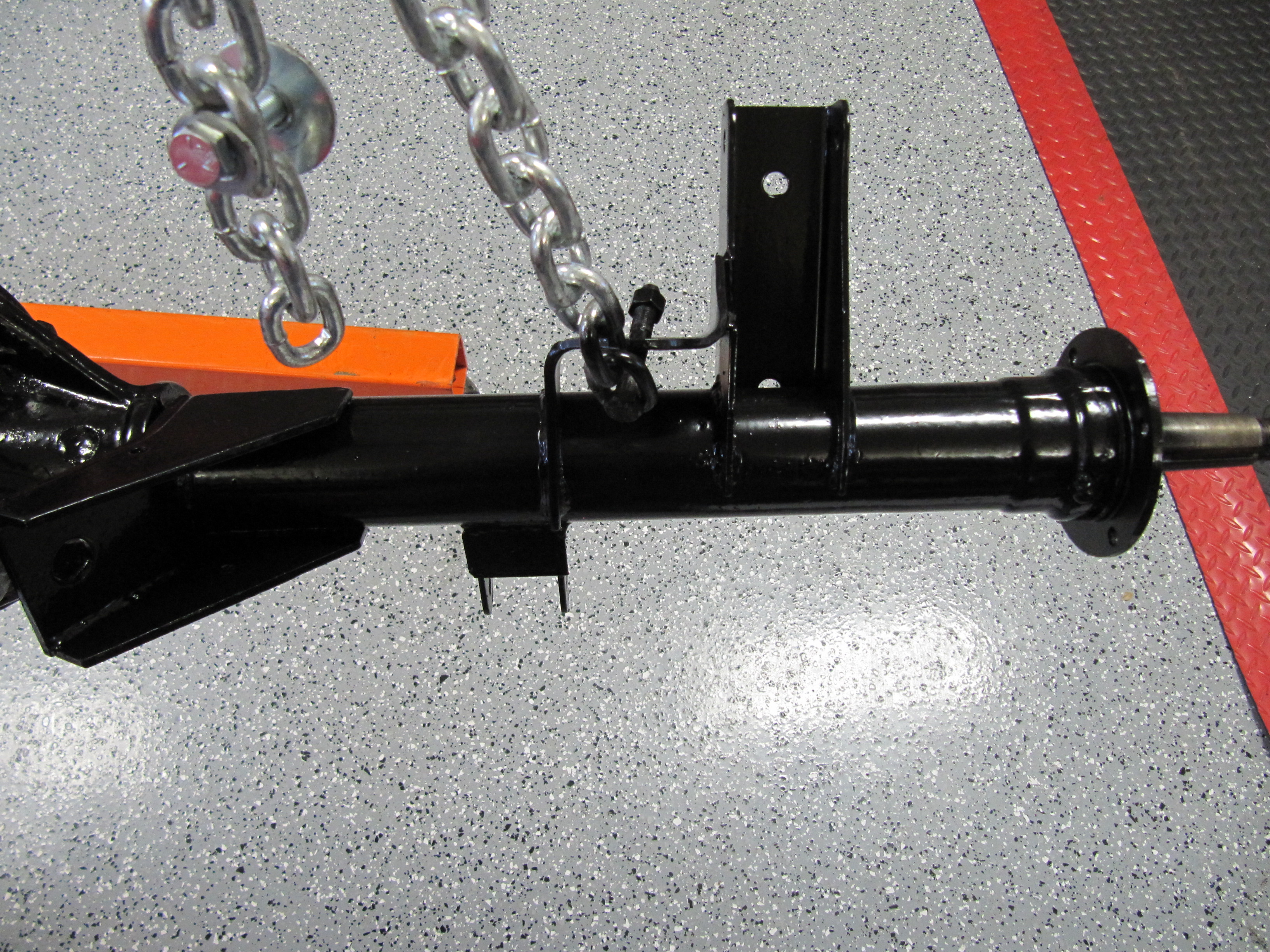
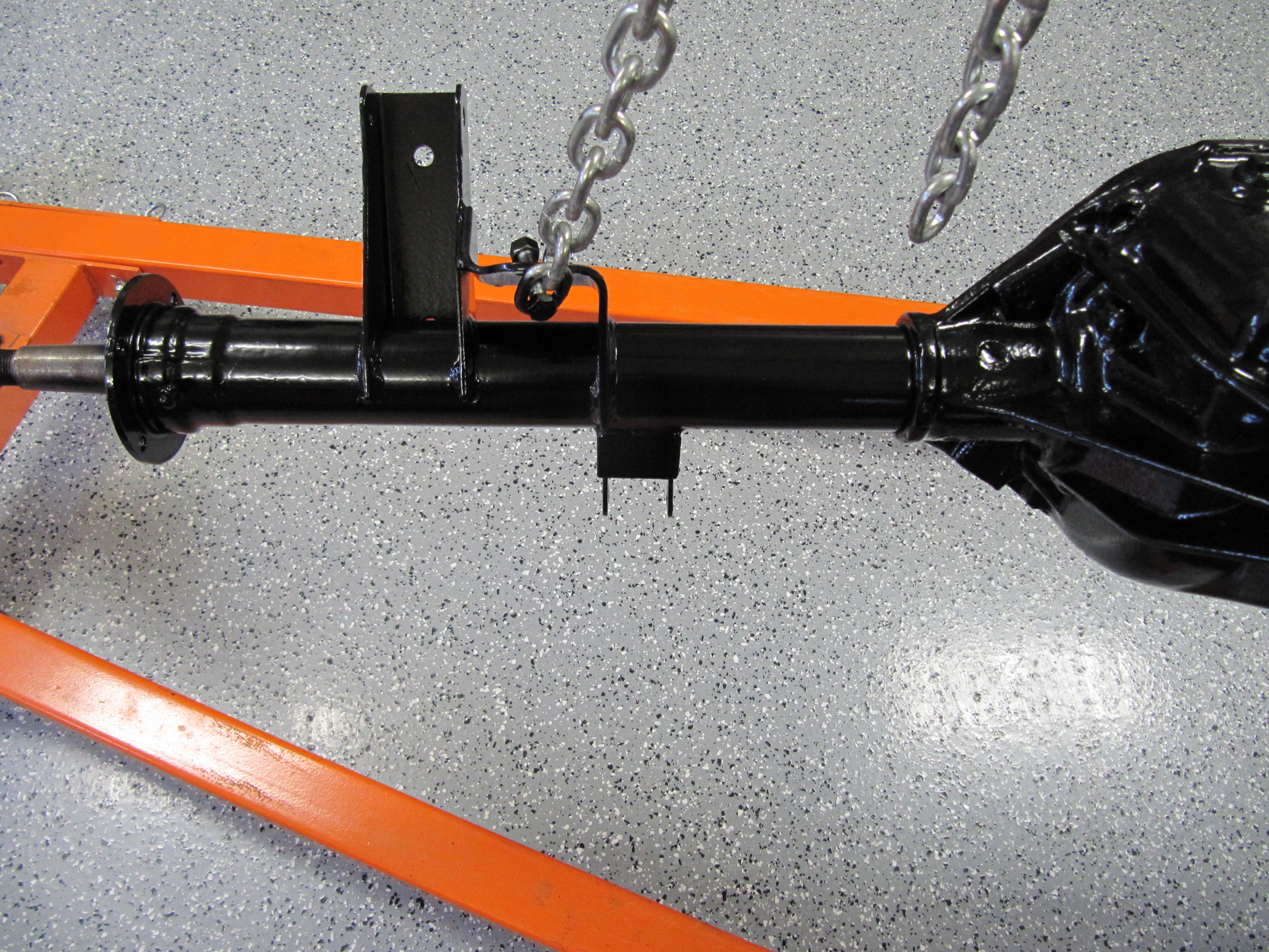
Installing the Axle and Springs
Based on comments of others, this is my plan for reinstalling the axle and springs into the car.
- Loosely mount the springs to the axle,
- Roll the axle under the car on the wheels and tires
- Lower the body to loosely attach the torsion rods
- Swing the springs up into the front mounts
- Raise the axle up into place
- Secure with the spring mount plate
zzz