Chapter 80 Week Fifty November, 26 2007


I had a little fun today, on the first day of December, 2007! I was able to drive the car, sans most of its bodywork, in the driveway and on our tennis court. Not far, but enough to enjoy the thrill of the progress to this point. I think the grin on my face says it all!

Pushed out of the garage

Almost a shame to cover it up with the body

Missing some body parts

Happy Day!

To the race track

Exhilarating!!


Chapter 79 Week Forty-Nine November, 19 2007


I am now waiting on Jack Harper to get free from his shop duties at Coachworks to come by the house and help me with starting and tuning the engine. While waiting, I took a few moments to check on 
sealing the firewall from fumes and heat emitted from the engine bay. I turned off the the lights in the garage and put a shop light in the engine bay and then inspected the firewall for any light coming through the firewall. As expected, I did find a few places, so I used a little 3M body caulk to seal the holes.

Another variance from originality on my project is the “personalized” arm rest. Its standard location makes it virtually useless as a functioning arm rest while driving. I am going to make a wooden box to fit the arm rest pad sourced from Heritage Upholstery and Trim to serve as a storage console and to lift the height of the pad to make it work as an arm rest while driving. I will cover the box with matching black carpet and hinge it at the rear of the pad. To begin my little project, I made a mock-up of the box from a cardboard shoebox. For me, 2 3/4” appeared to be the proper height of the box, with the cushion on top of the box.

Arm Rest Prototype

Jack Harper came over to the house and we readied the engine for starting. First, we connected the cables for the throttle and choke. While the previous injection of oil through the engine should have sufficiently lubricated everything, I still pulled the spark plugs and turned the engine with the starter until the gauge showed oil pressure. I put 5 gallons of fuel in the tank and we turned on the ignition to try out the fuel pump. The carb float chambersfilled and we were then ready to try firing up the Bloody Beast.

We reinstalled the spark plugs, turned on the ignition and hit the starter button. After about 10 seconds we had the engine running! Jack ran the engine up between 2,000 and 2,500 rpms and then we adjusted the carbs to bring the idle down to about 700. After 30 years another Healey is saved and running. It was an exciting moment.

I did have two problems to be fixed. I had taken apart the hot water valve, cleaned it, reassembled and installed it on the engine. It leaked! So I ordered a new one to replace the original. The second problem was my own stupidity! I did not replace the  Toyota gearbox real oil seal and I quickly discovered that I should have as a pool of MT-90 formed under the car. New seal ordered also. Cannot wait to get both pieces, install them, and get her running again!

Chapter 78 Week Forty-Eight November, 12 2007

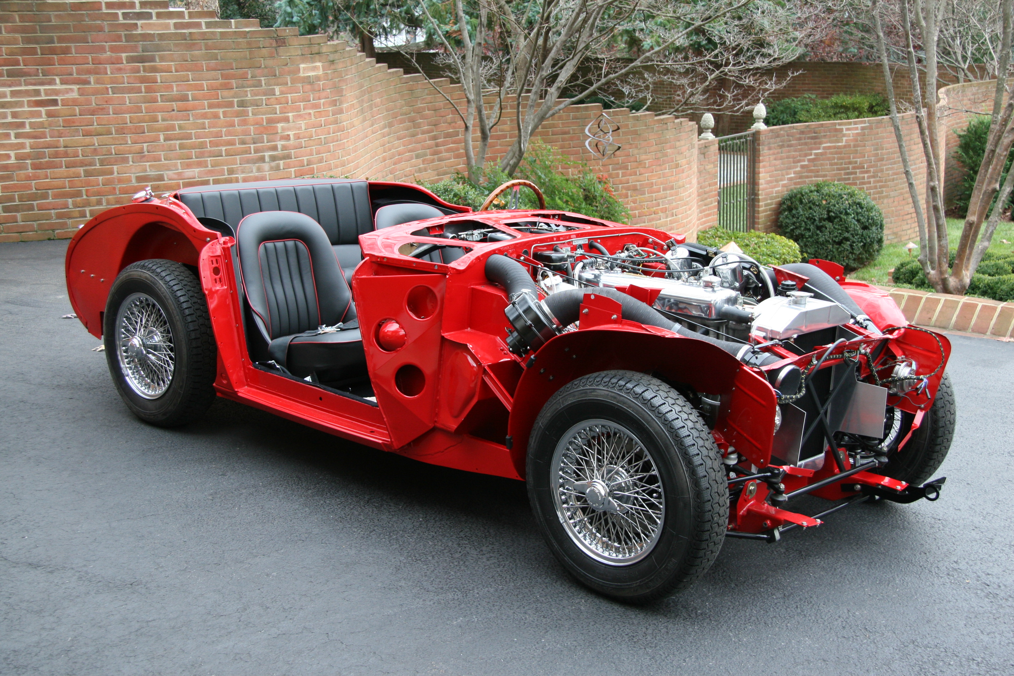
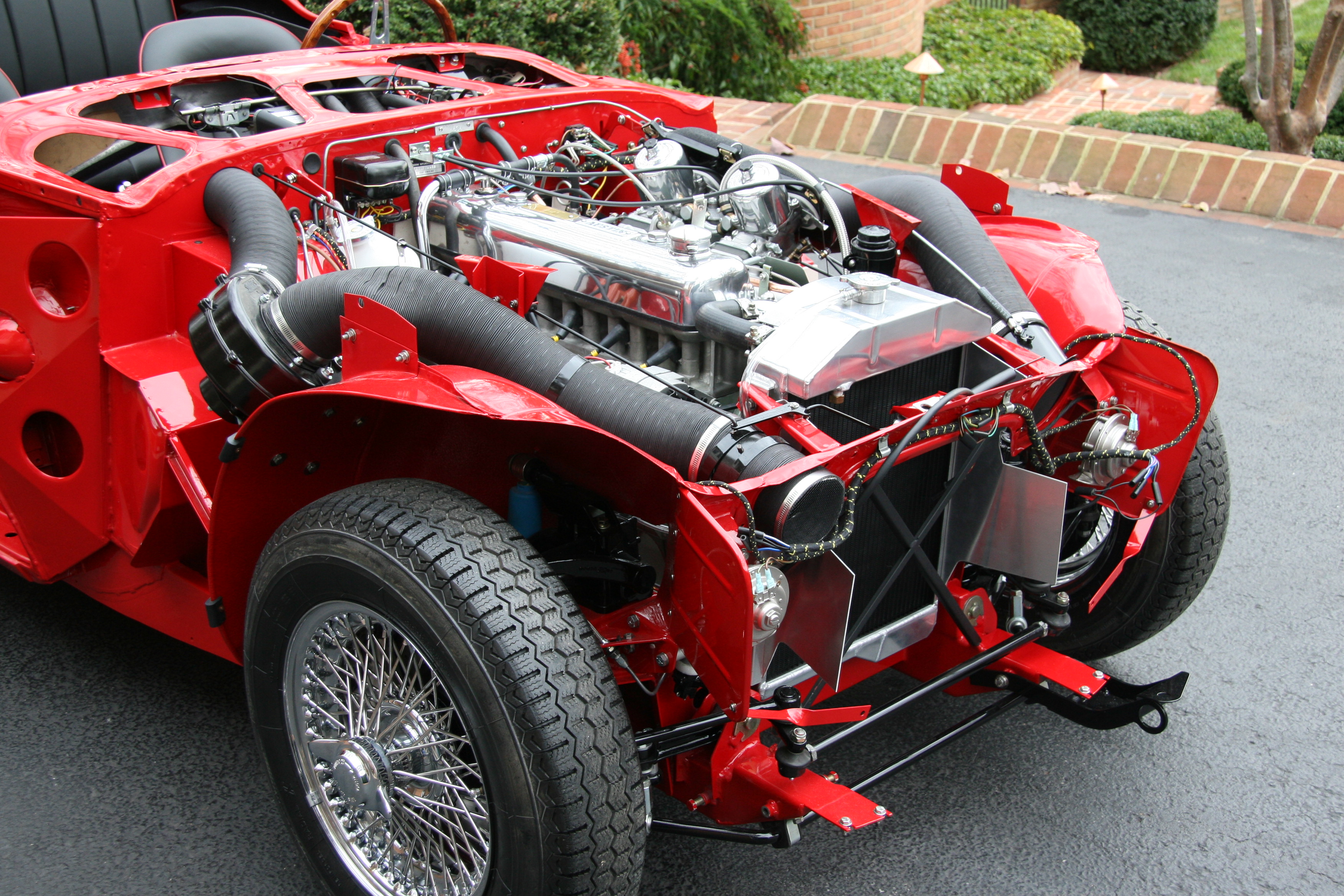
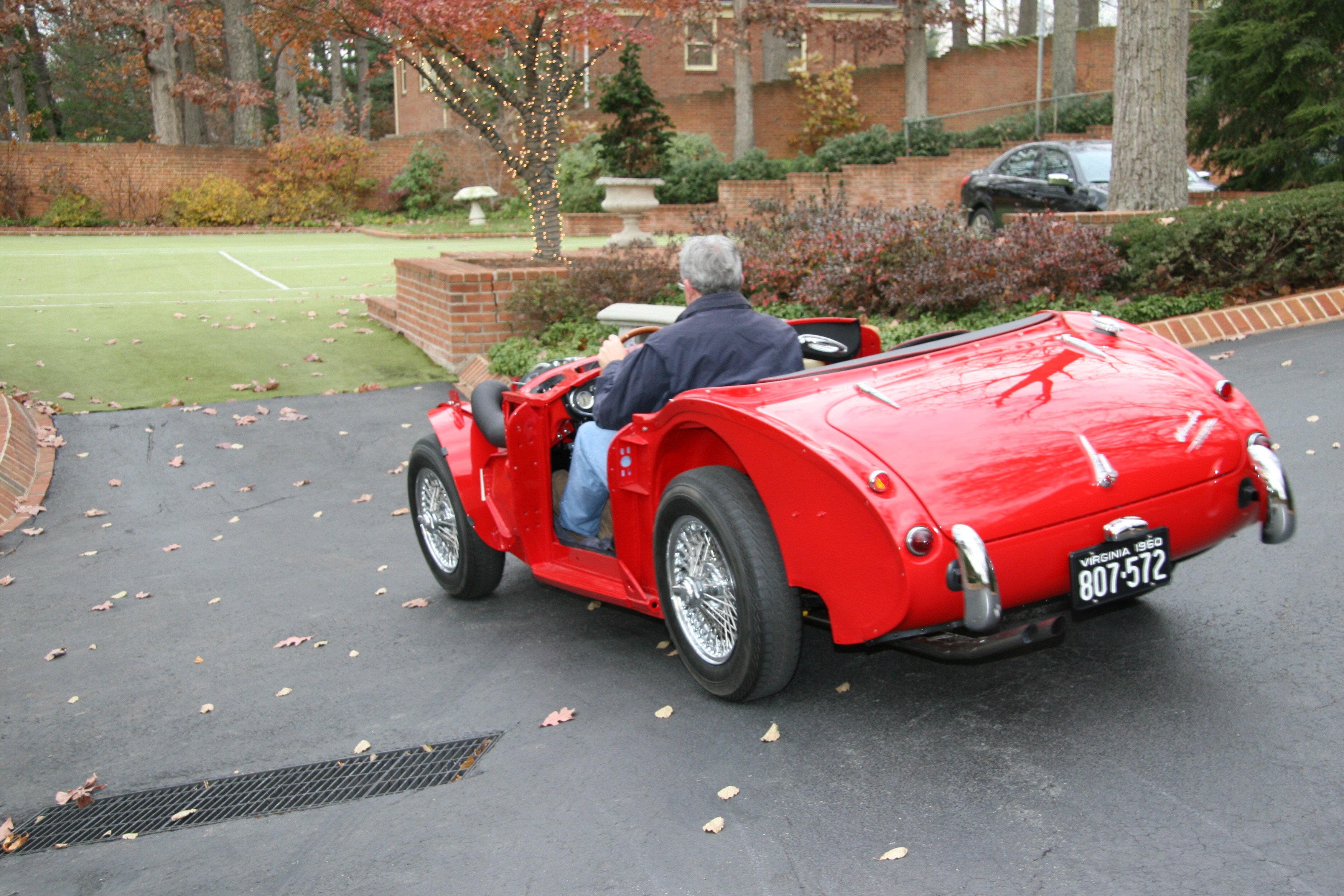
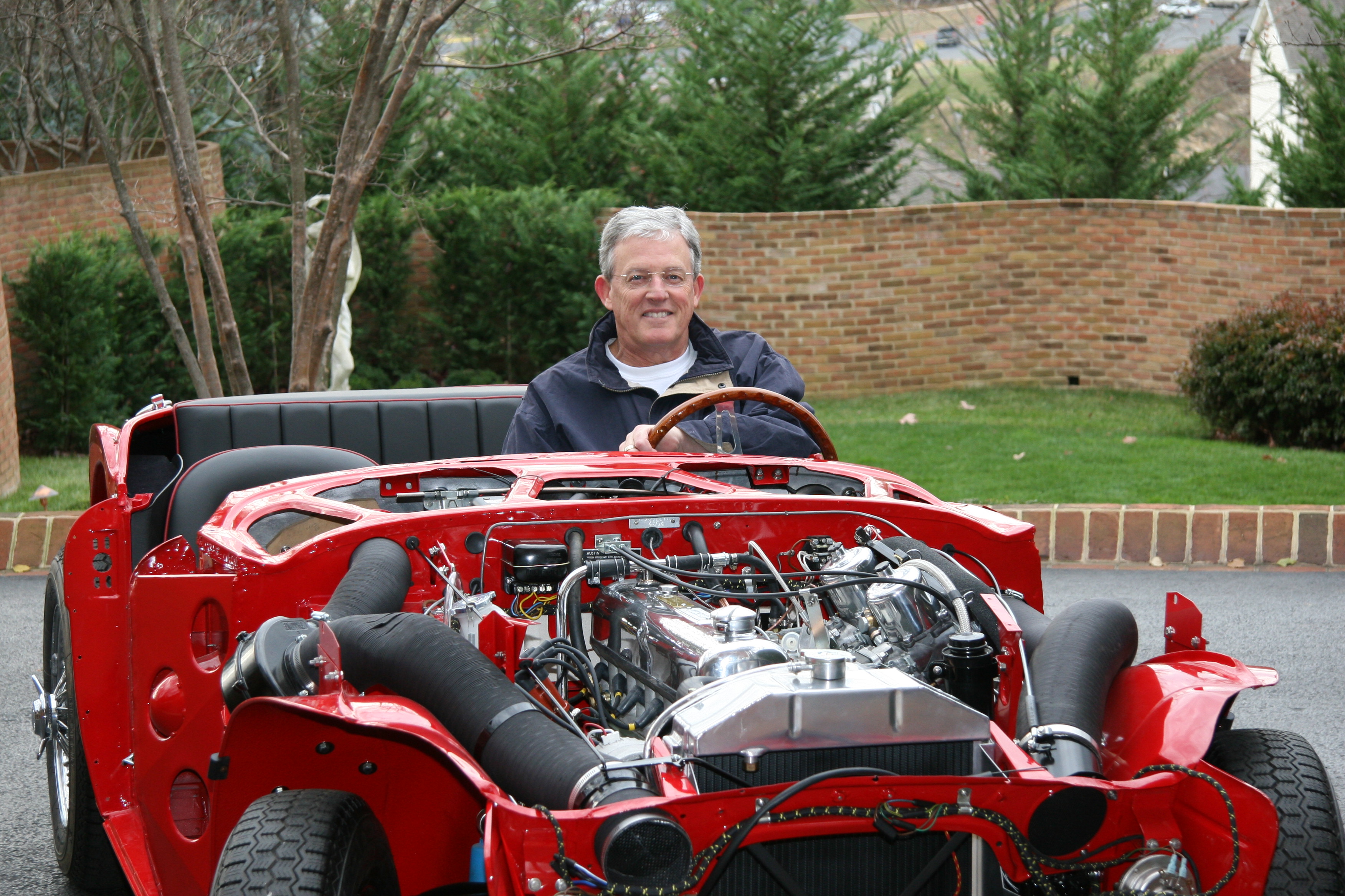
I ordered some 6mm black rubber tubing from British Wiring to sheath the choke cables. It gave a slightly loose fit, but I think it will be fine. I installed it on both cables. I painted and installed the propshaft made for me by Dale Engineering.

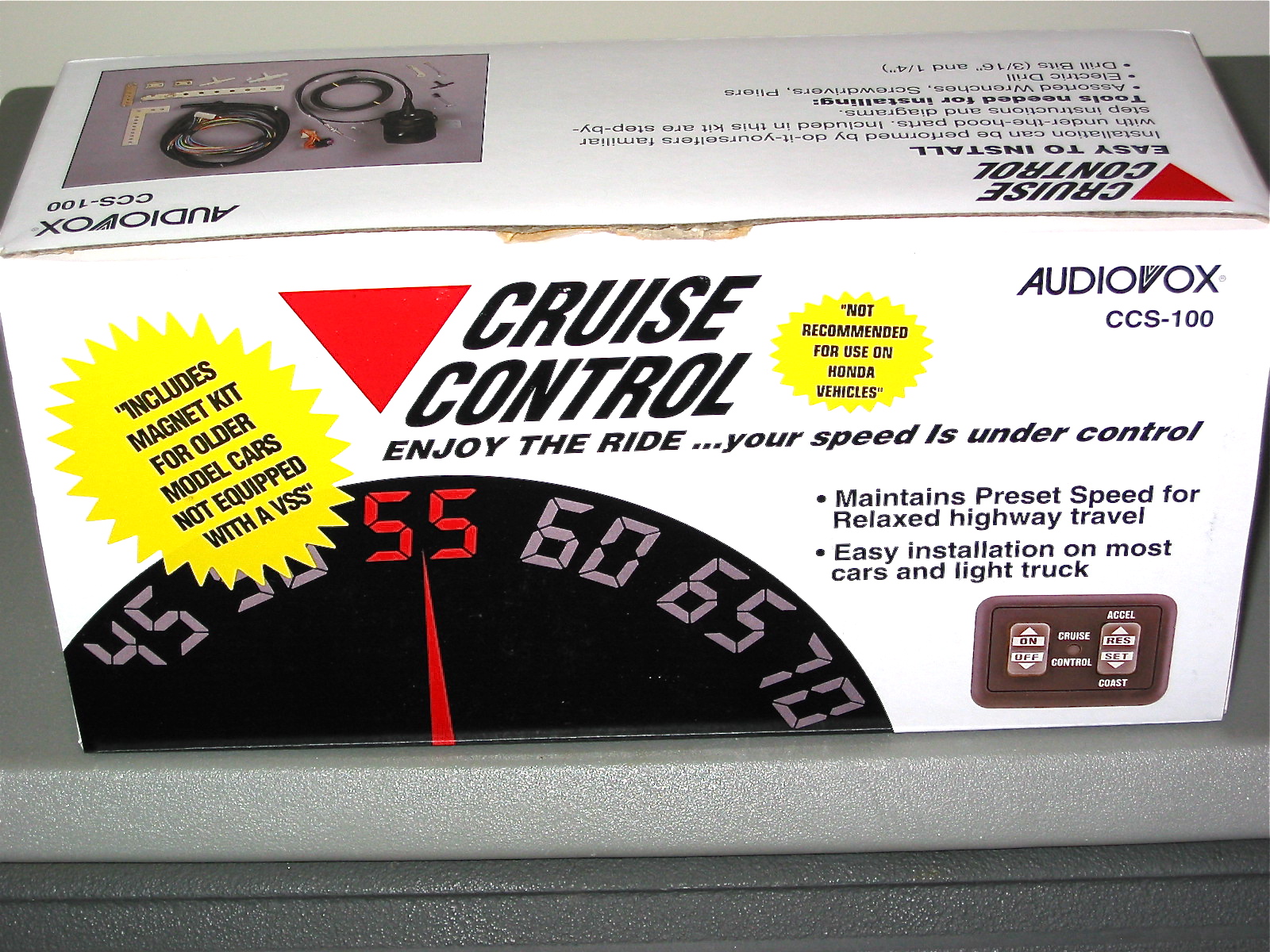
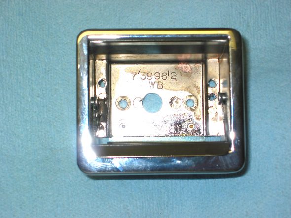
I purchased the cruise control unit, made by Audiovox, from J. C. Whitney.

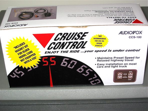
Audiovox cruise control

It was fairly inexpensive and appeared to be a high quality kit. A complete set of installation instructions is available from the Cruise Control pdf document I created. Not much helpful information was available from other Healey owners who had done the install, although I did find one well done article that is in the October, 2002 edition of the Healey Marque Magazine. Alan Teague and Carl Brown from North Carolina did provide some useful tips and photos and I am grateful to both of them. Installing the Audiovox CCS

(This is a large file that takes a while to open, be patient)

The key components included installing the magnet and sensor at the propshaft, the location of the servo canister, the vacuum line and throttle connections, the control module, and the wiring.

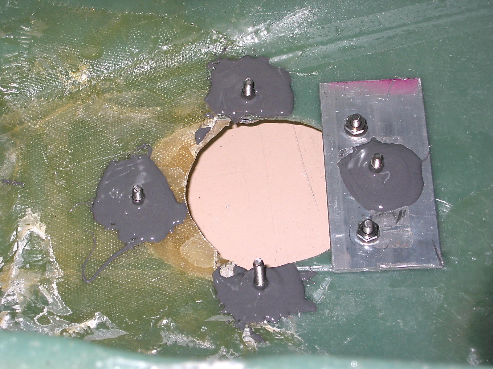
I installed the servo above the dash panel support bracket to the right of the steering column with two 11” plastic ties, rather than using the supplied metal bracket. I know from other’s accounts that the unit makes some noise when it is operating, but not knowing if it is an offensive level or not, I wanted to mount the servo temporarily. If the unit turns out to be noisy, I will move it into the engine bay later.
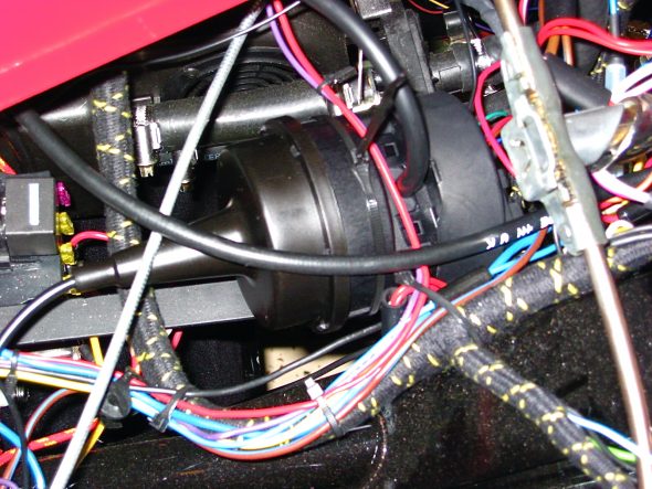
Servo installed

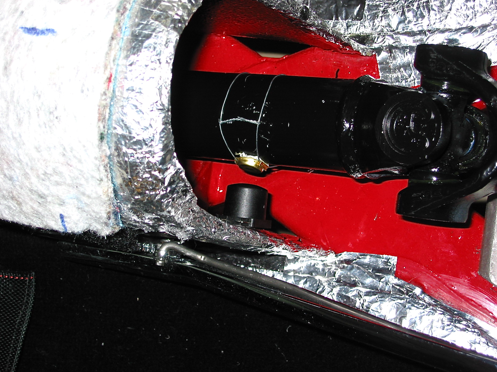
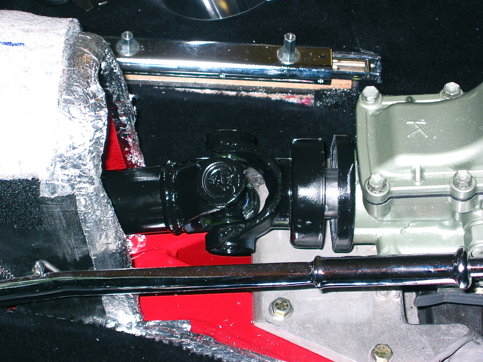
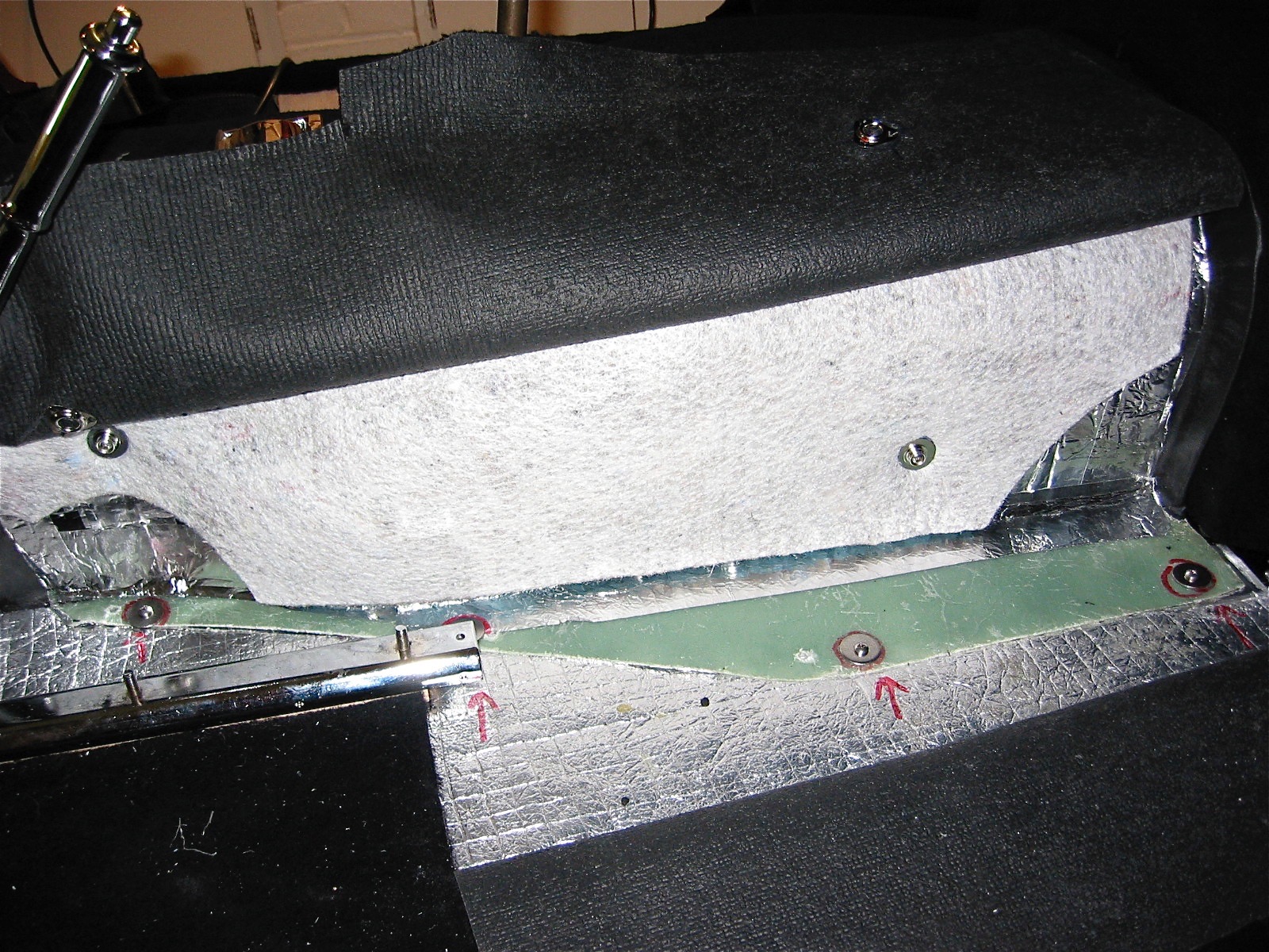
Wiring the magnet to the propshaft should really be done with the shaft removed from the car if you want to do a nice installation. I located the magnet while the propshaft was in the car, aligned the sensor and mounted it on the right side of the gearbox tunnel, removed the propshaft and safety wired the magnet and then reinstalled the propshaft. If you want to do a nice job, I highly recommend using safety wire twisting pliers. They make the job much easier and result in higher quality work. I got my pliers from Aircraft Spruce.

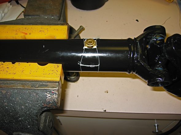
Cruise control propshaft 6

Cruise control driveshaft sensor 2

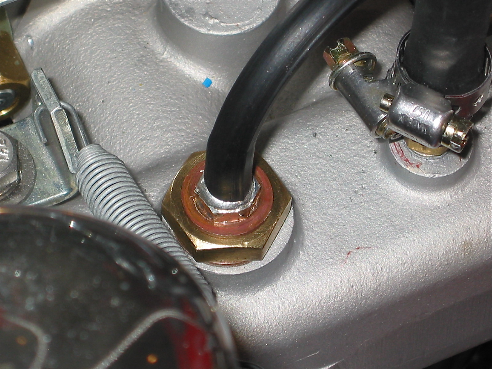
Installing the supplied rubber vacuum line required taking the line through a firewall rubber grommet that was not previously used, and then modifying the larger nut on the intake manifold with a fitting to permit connecting the hose for vacuum at the manifold.

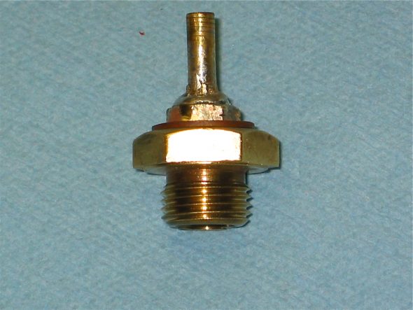
Homemade vacuum fitting

Cruise vacuum fitting 1

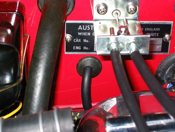
Cruise Vacuum Line grommet

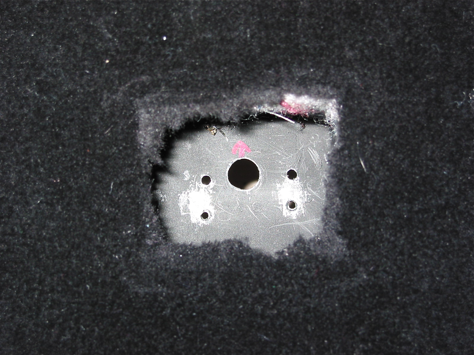
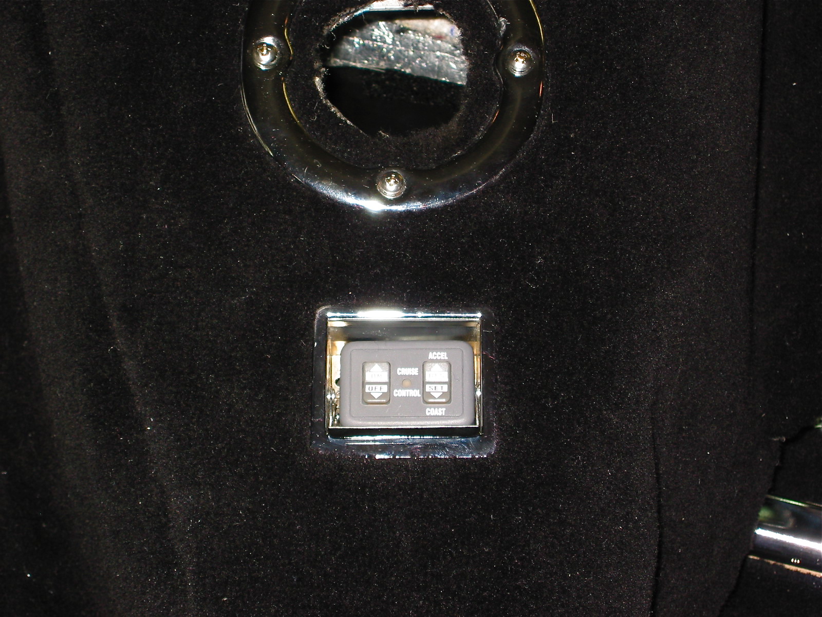
After setting up the magnet, sensor and vacuum servo the next task was to complete the installation of the cruise control panel. I followed the course of others, taking advantage of the panel’s small size and installing it in the ash tray. This provides a convenient location for controls and also “hides” the panel when desired. I simply drilled a 1/2” hole in the bottom of the ash tray and in the gearbox tunnel bracket for the ash tray to permit the routing of the wiring.

Modified ash tray for cruise 1

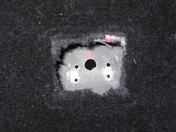
Modified ash tray for cruise 2

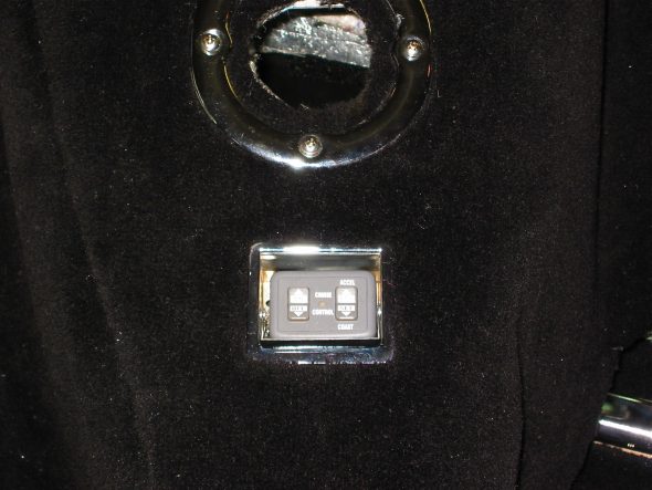
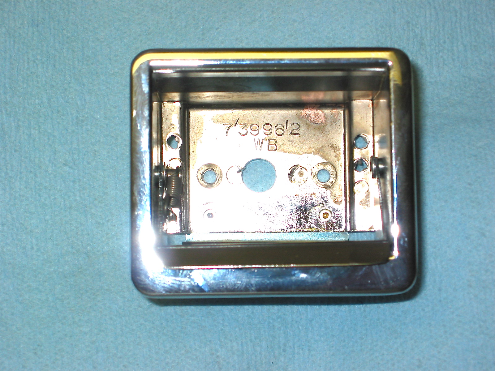
Cruise control panel

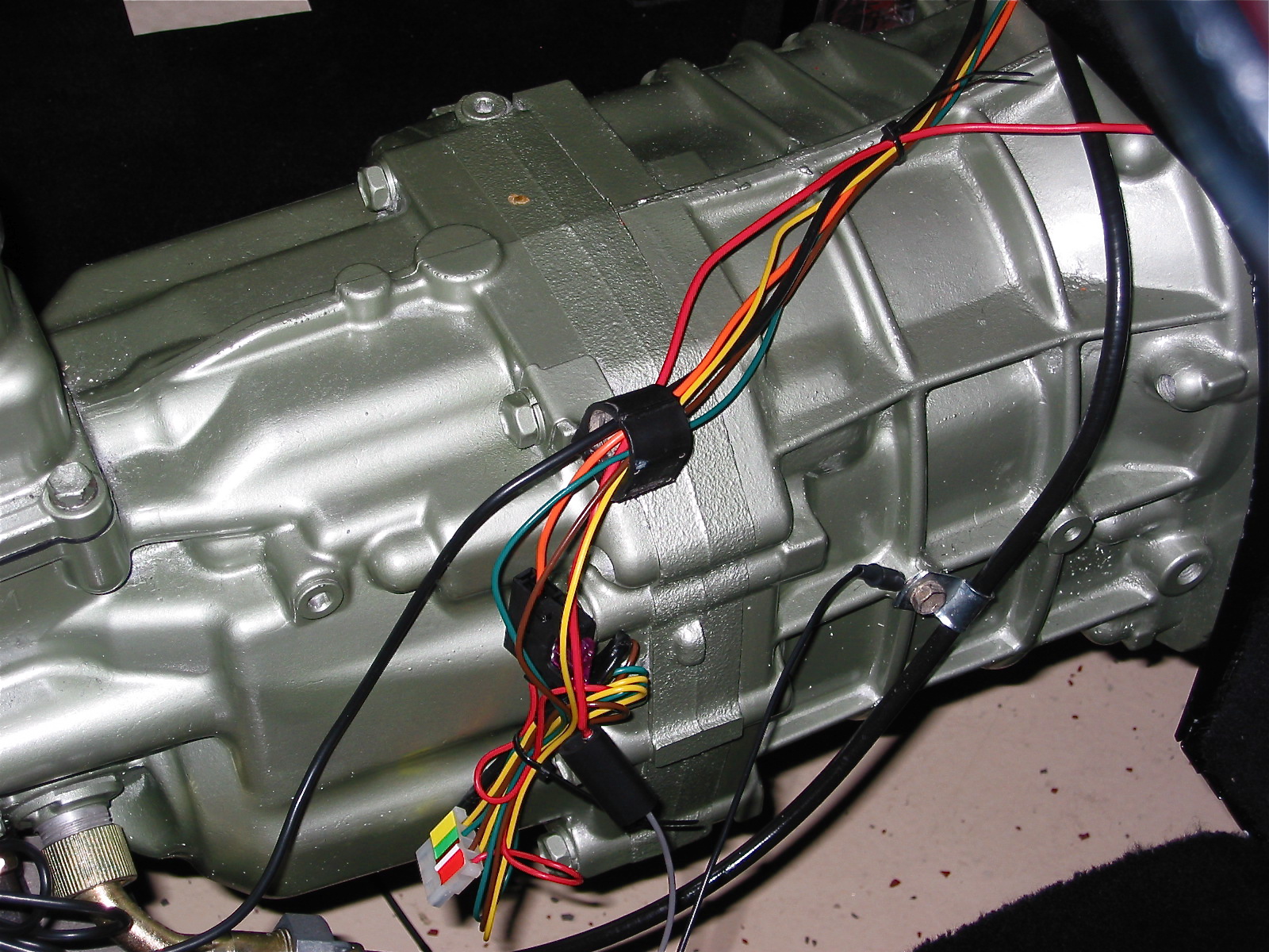
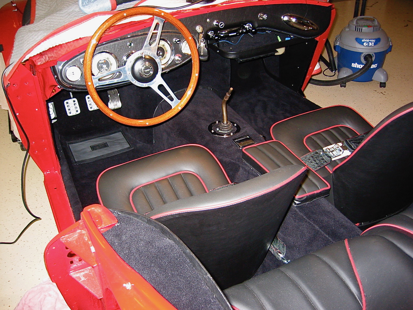
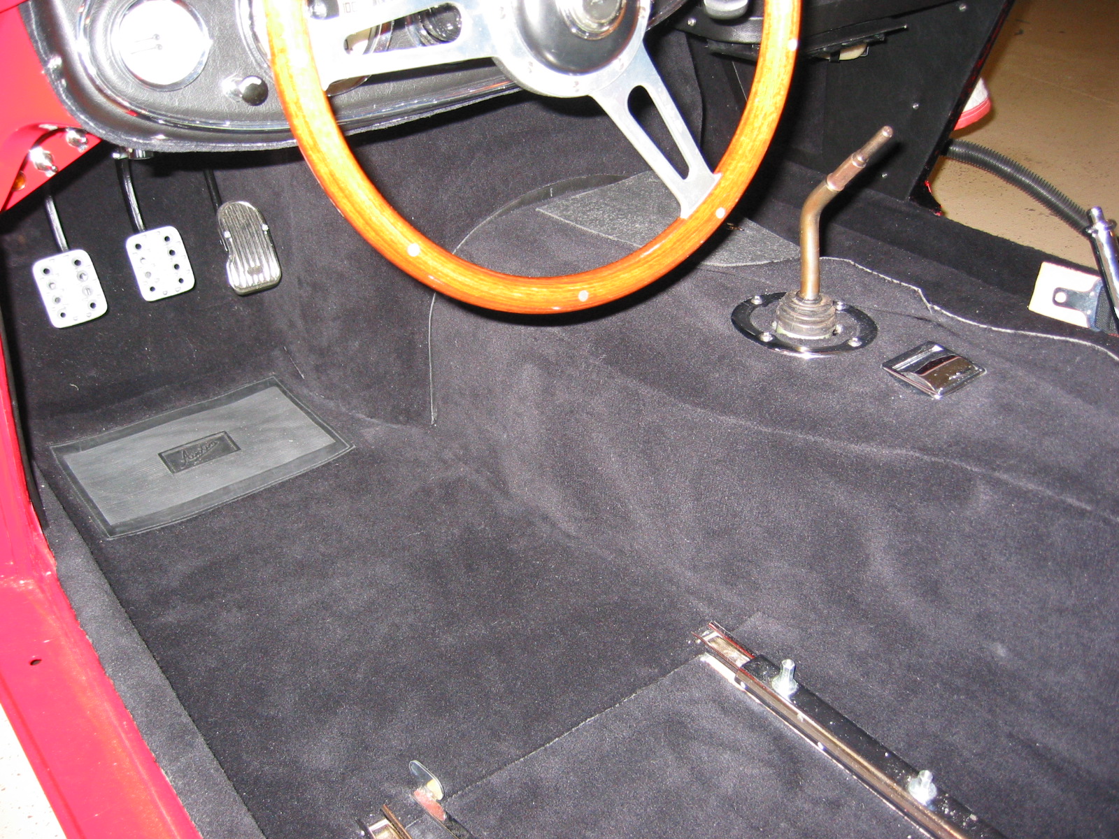
The cruise control wiring appears daunting at first, but with patience it can be accomplished by a novice. Since on the BT7 the speedometer cable runs behind the gearbox extension, I decided to run the cruise control wires down the same path to get all of my wiring “under” the gearbox cover. Again, details are provided in the Cruise Control pdf file. Black, twin tailed wire to the magnet sensor, black single wire to ground, grey wire to headlamp switch for illumination of the control panel in the ash tray, red wire to the light green wire on the brake switch that is hot whether the brake pedal is depressed or not, the purple wire to the green/purple wire on the brake switch (the one that is hot when the pedal is depressed), blue wire to (-) terminal on the coil, yellow, green and purple and red wire to the 4-pin connector, the orange fused wire to a power source when the ignition is switched on.

Cruise witring along gearbox

With the wiring complete, the only remaining task is locating and connecting the throttle control. That job will have to wait for next week’s work.

Chapter 77 Week Forty-Seven November, 5 2007

In final preparation for starting the Bloody Beast, I installed the propshaft and filled the Toyota gearbox with just shy of 3 quarts of MT-90 oil using the side filler hole and filling until oil started to dribble out of the filler opening.

Propshaft installed

I had been waffling on whether or not I would install the ash tray in the gearbox cover, but I decided to go ahead and do it. If I equip the car with cruise control, it will serve as a great location for the control module. I cut a hole in the fiberglass cover an JB welded the bracket to the cover. The next step was to cover both sides of the gearbox cover with Dynamat Extreme.

shift ring JB Weld

Gearbox cover with Dynamat 1

Gearbox cover with Dynamat 2

Fitting the carpet and padding to the gearbox cover was not a job that I had been looking forward to doing. Not so much hard as awkward. I installed two carpet snaps through the padding provided by Heritage Upholstery and Trim on each side of the fiberglass gearbox cover. I installed these with #6 machine screws with large washers and nuts, rather than with self-tapping screws since I was fastening to fiberglass instead of metal.

Gearbox padding

I also cut some padding to go over the end of the gearbox tunnel and I fit it with velcro. The carpet was carefully cut to fit through trial and error with the help of some chalk. Holes were drilled in the gearbox cover flange and the assembly was mounted to the car. Everything seemed to be nice and tight, although I will do some seam sealing to the underside of the assembly before completing the job. I was satisfied with the final product!

Carpet installed 3

LH carpet installed 2