I am making this post to provide documentation for others on the subject of 1-2-3 electronic distributors and their installation in Big Healeys. There isn’t too much content regarding the 1-2-3 distributors on the Healey Forums, but I suspect that I am not the only one using this product from the Netherlands. I am not writing this to promote the product or even to encourage others to use it, although I have been very happy with my installation.
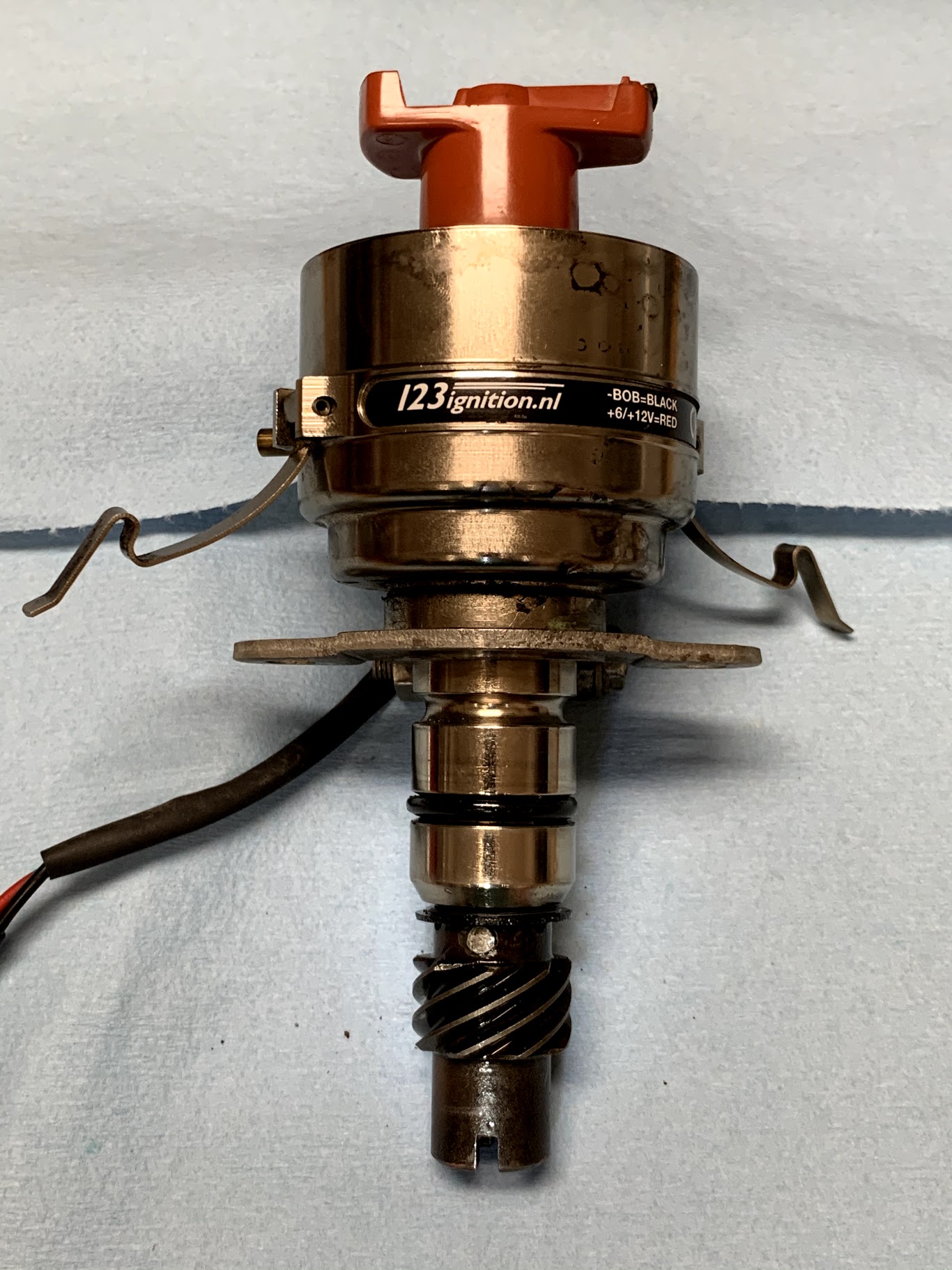
I have been using my 1-2-3 since about 2008 though I have never contributed much on the various Forums and bulletin boards about it. A programmable bluetooth unit allowing the owner to to test various advance curves using his/her laptop is now available. However, I purchased mine before that technology was on the market. You can check out their website (or at least the USA marketer) at https://123ignitionusa.com/6-cylinder-lucas-distributors/ for info on the unit I used – 123\GB-6-R-V, or for other models. The unit I purchased has 16 different advance curves. The owner is given parameters for each of the curves and you select the one you want by simply turning a small “click wheel” on the side of the distributor to your choice. In my case I am using the “B” profile.
Click here for the 1-2-3 Installation Instructions and for information regarding the sixteen advance curves.
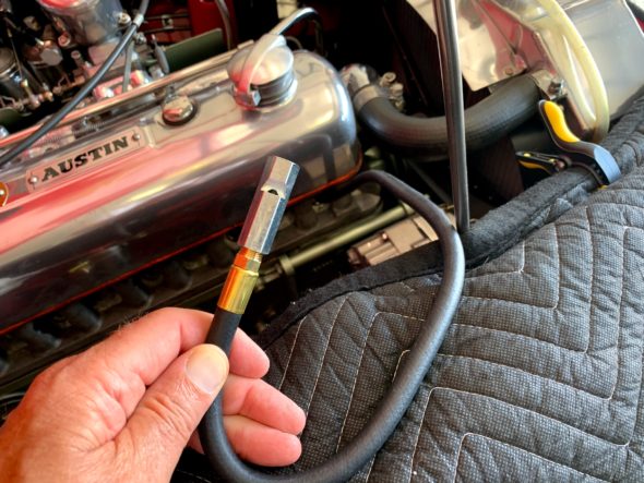
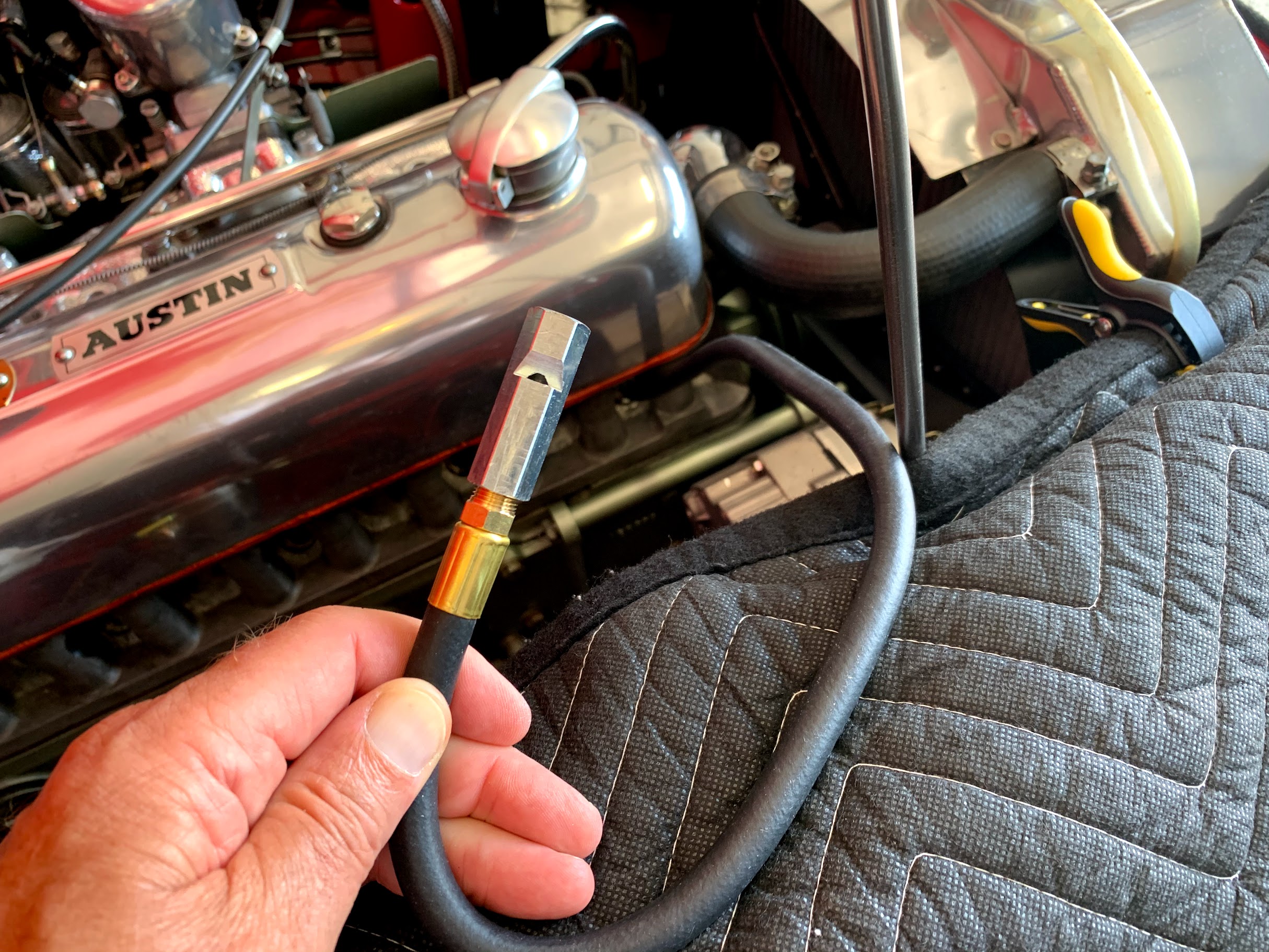
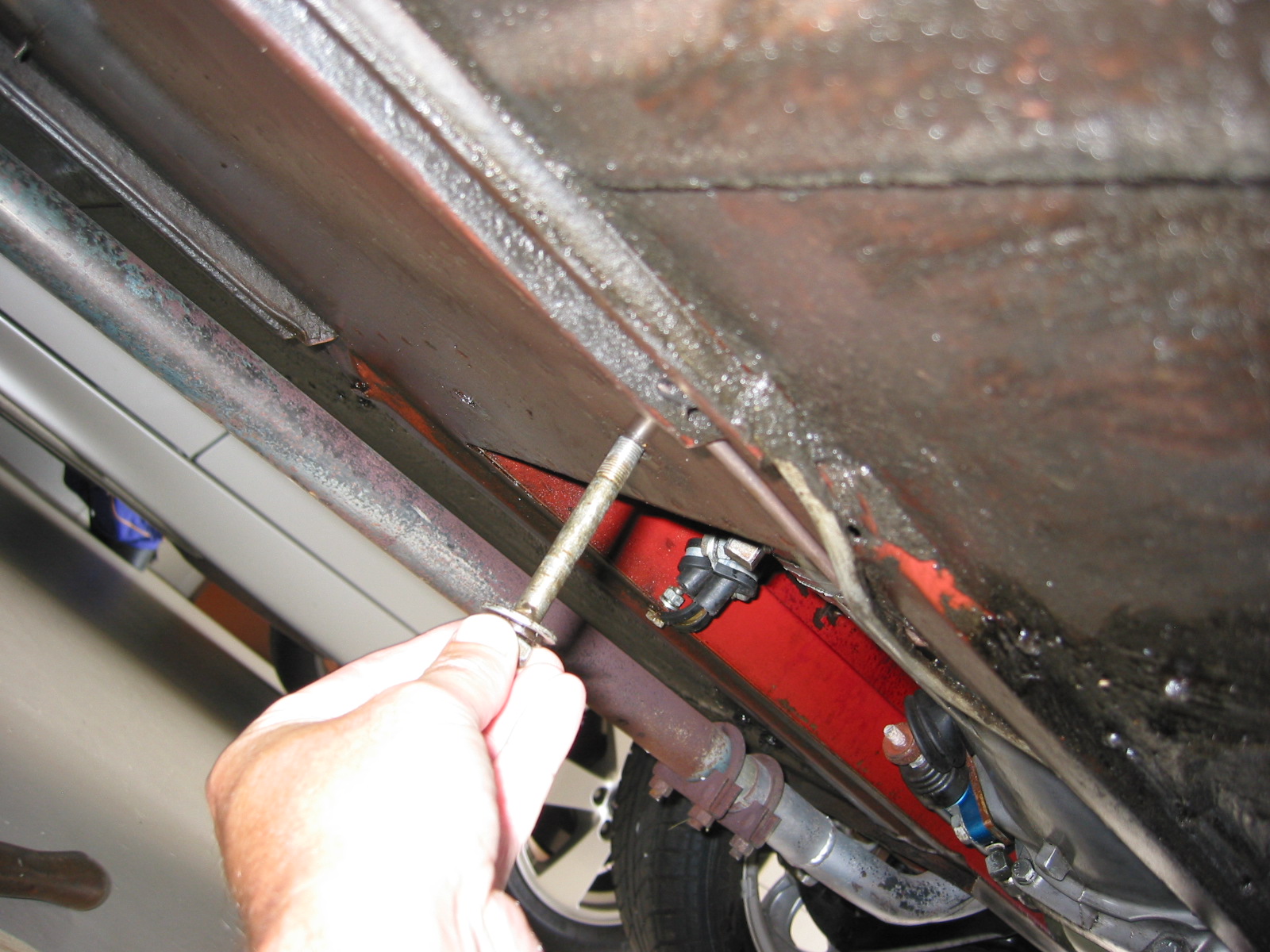
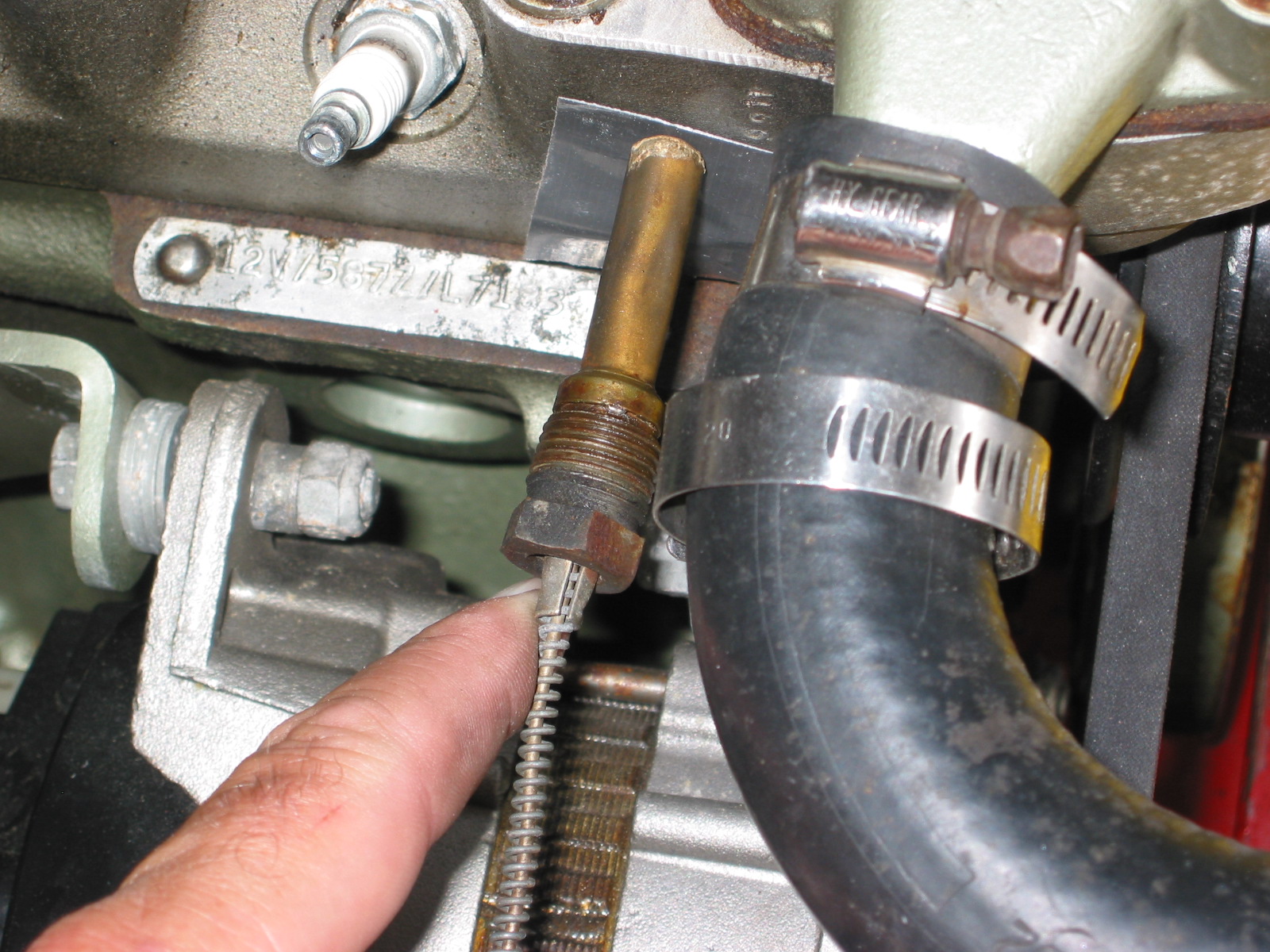
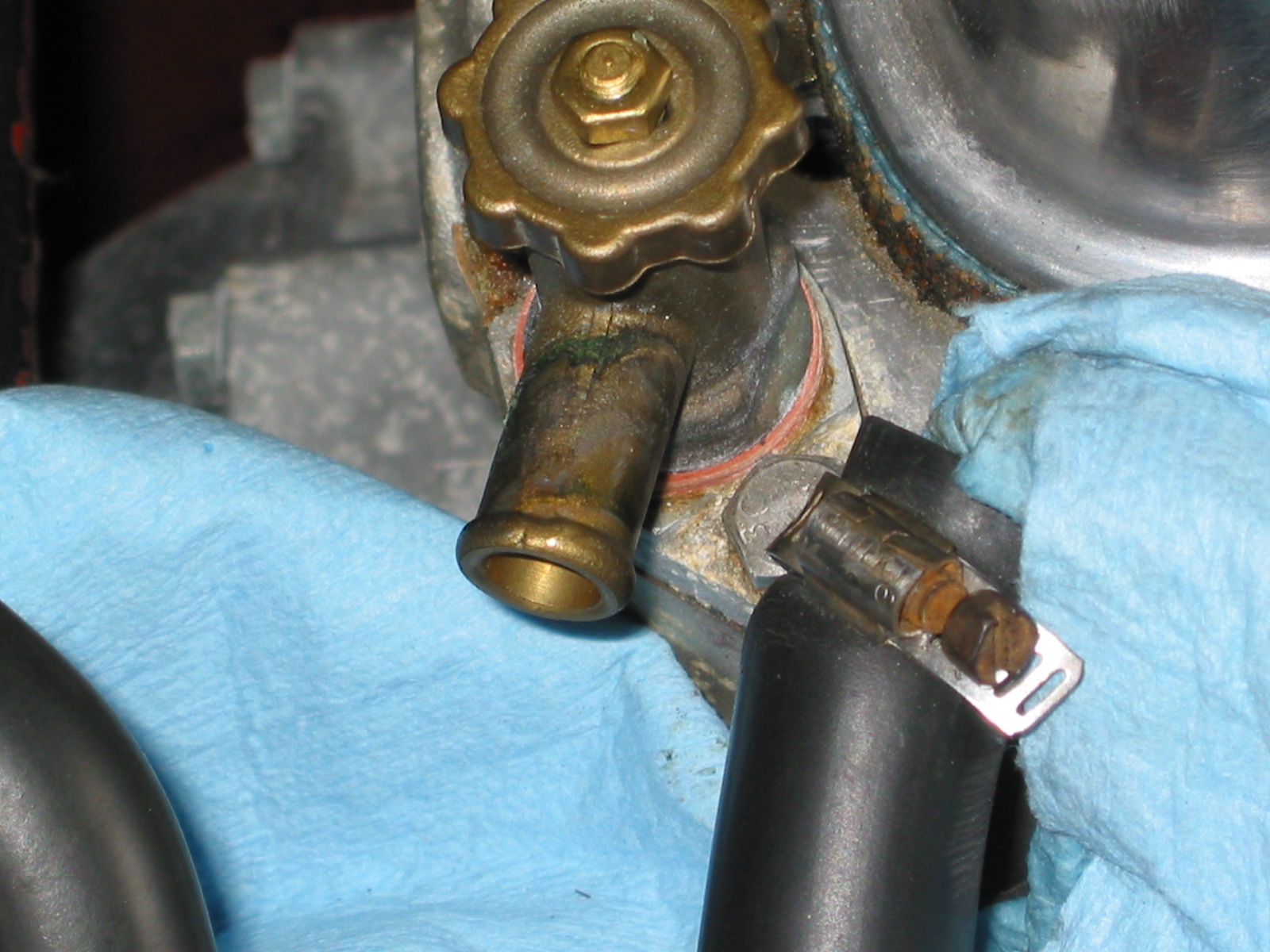
Top Dead Center Whistle Tool
I like to begin the installation process by first getting the #1 cylinder piston at top dead center on the compression stroke. There are a number of ways to accomplish this, but in my case I used a whistle on a hose screwed into the spark plug location for the #1 cylinder.
This is a neat little tool! I removed all of the spark plugs and put the car in fourth gear. I then pulled the car forward. I prefer to pull rather than push because it is much easier to watch the pointer and pulley and to hear the whistle. I passed the point where the timing gear cover pointer and the pulley mark aligned with no whistle, and concluded that the piston was elevated but on the exhaust stroke. I continued to pull the car forward and slowly approached the intersection of the marks a second time. Sure enough, as the pulley mark began to near the pointer the whistle started making its noise. This lasts a little longer than one might think. I stopped when the pointer and the pulley mark aligned again (and the whistle stopped blowing) knowing that I had achieved top dead center on the compression stroke.
The 1-2-3 distributor is not set-up out of the packaging for earlier Healeys with tachometer drives. While the distributor is a “drop-in” in for the BJ8 with an electronic tach, a kit is supplied to adapt it for the mechanical tach drive of the BT7. The shaft did need to be drilled and the drive dog from the original Lucas unit installed with a few spacing washers.
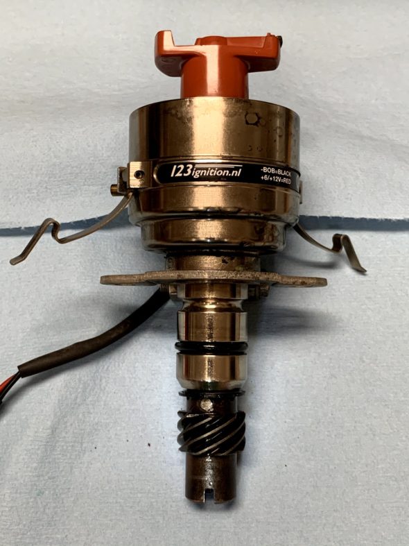
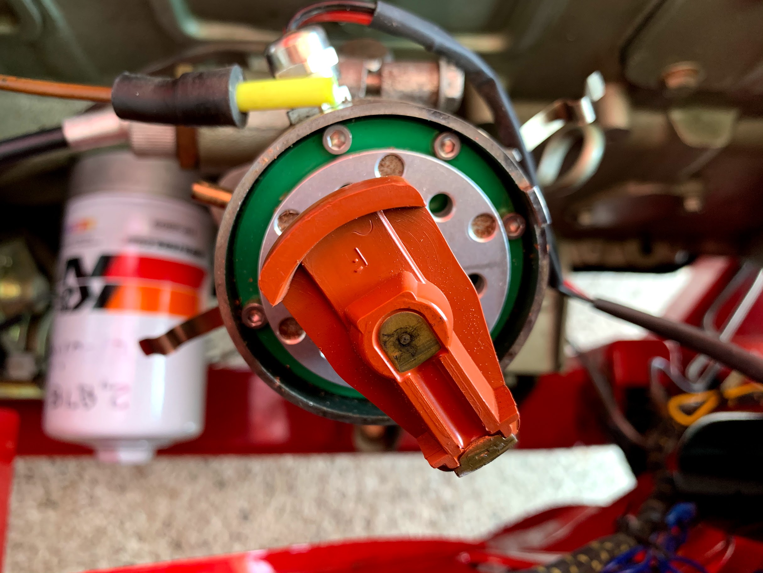
1-2-3 Distributor Rotor Alignment
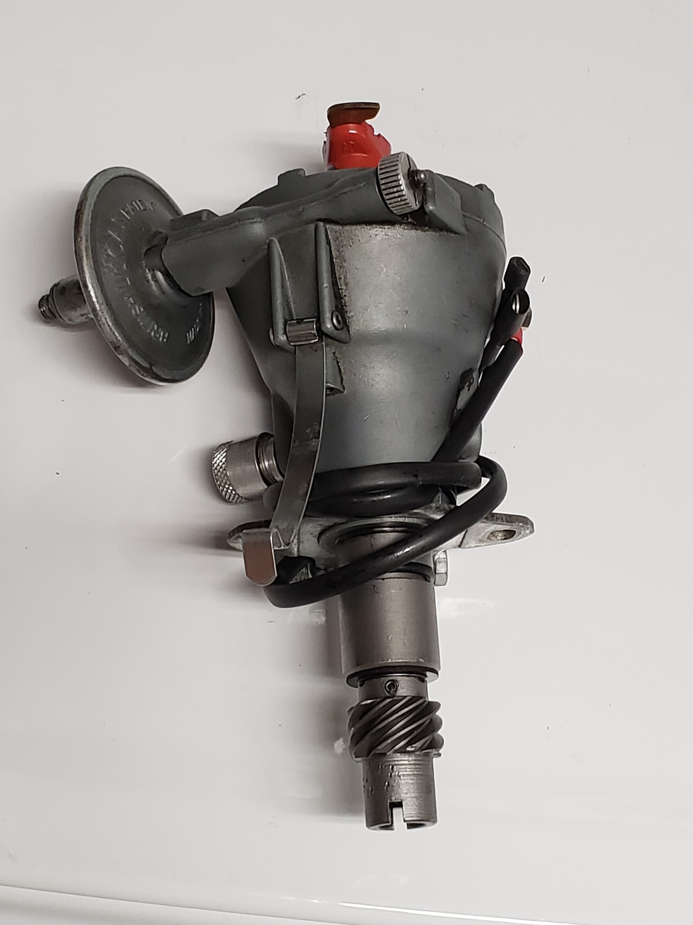
Note that with the shaft lined up identically, the Lucas DM6A rotor is in line with the slot at the bottom of the gear. (Thanks, Steve Gerow for the photo). While the 1-2-3 distributor is clocked 90 degrees out from the Lucas distributor.

Lucas DM6A Distributor
This means that unless one manipulates the distributor driving gear (AEC242) from its original “twenty-to-two” position, the rotor will not point in the 2 o’clock position to approximately the #1 cylinder spark plug when the first cylinder piston is at top dead center on the compression stroke. If you don’t mind that your #1 cylinder spark plug is fed by a lead wire from the distributor’s 5 o’clock terminal then you are ready to go. Simply begin the numbering sequence of 1-5-3-6-2-4 moving counterclockwise for your ignition wires.

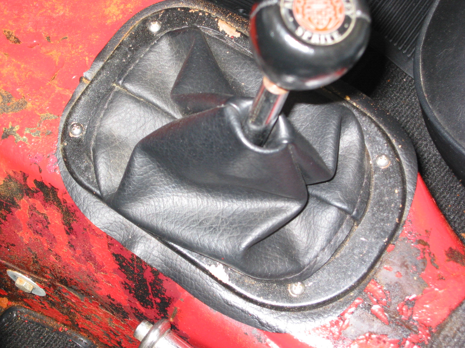
1-2-3 5 o’clock Rotor Position
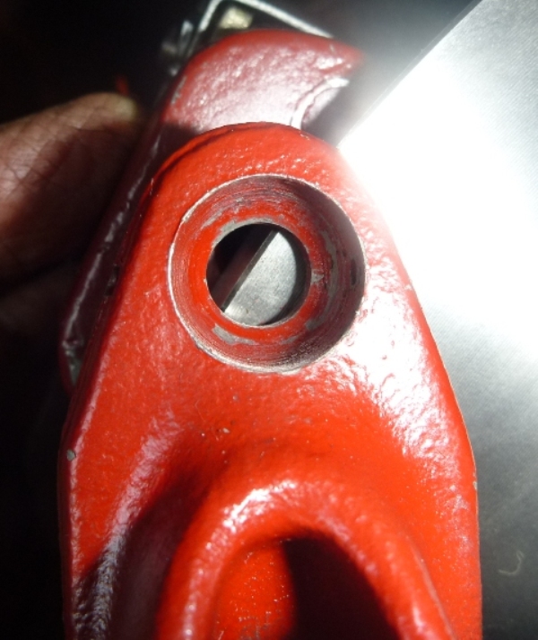
However, If you want your wiring scheme to look “normal,” this can be accomplished quite easily. Note that when you observe the tachometer spindle in the tachometer drive housing the slot in the shaft is not centered. It is offset with the smaller segment in the downward position.
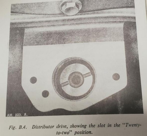
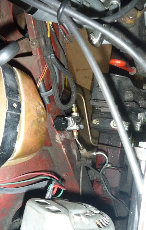
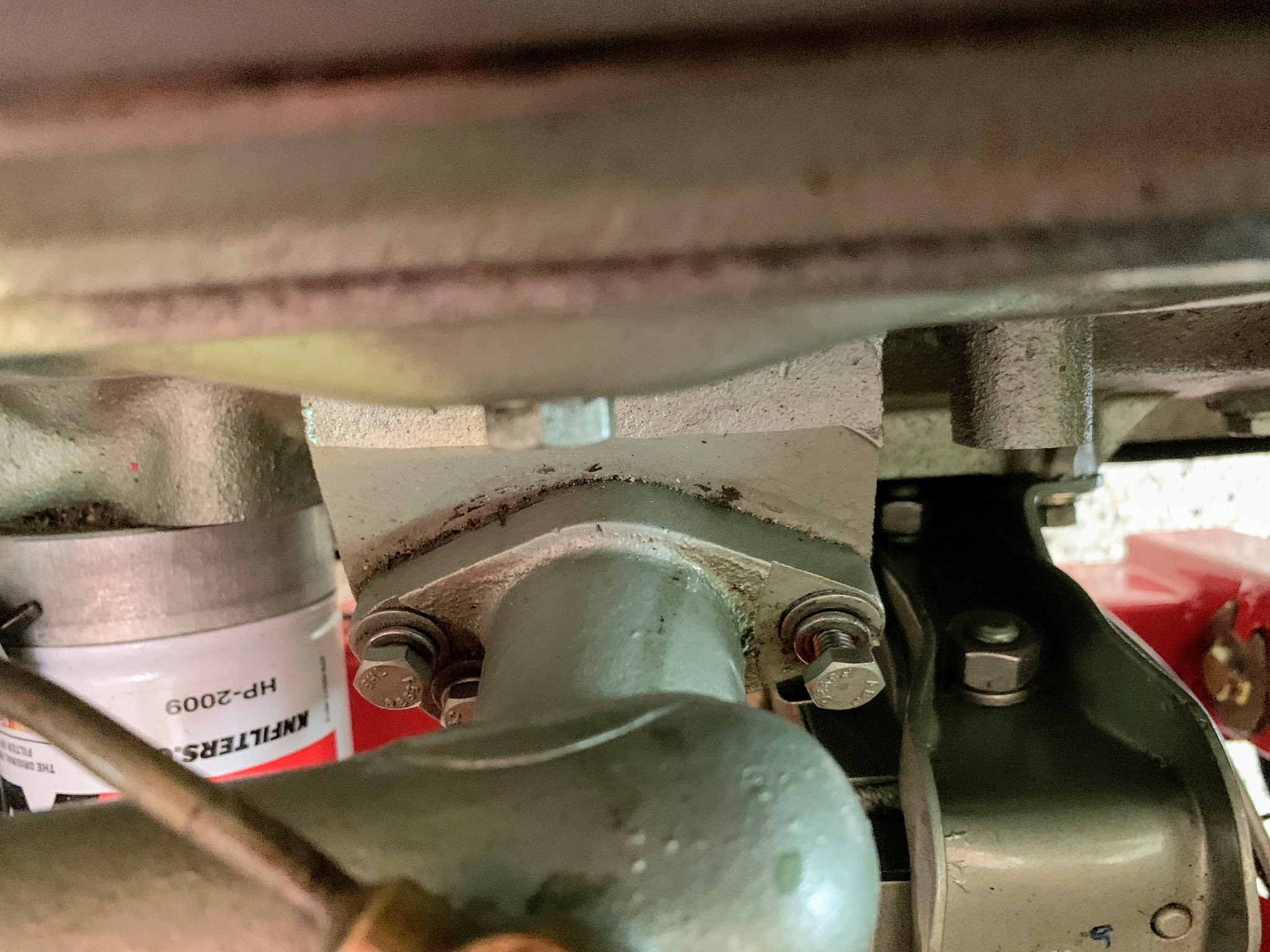
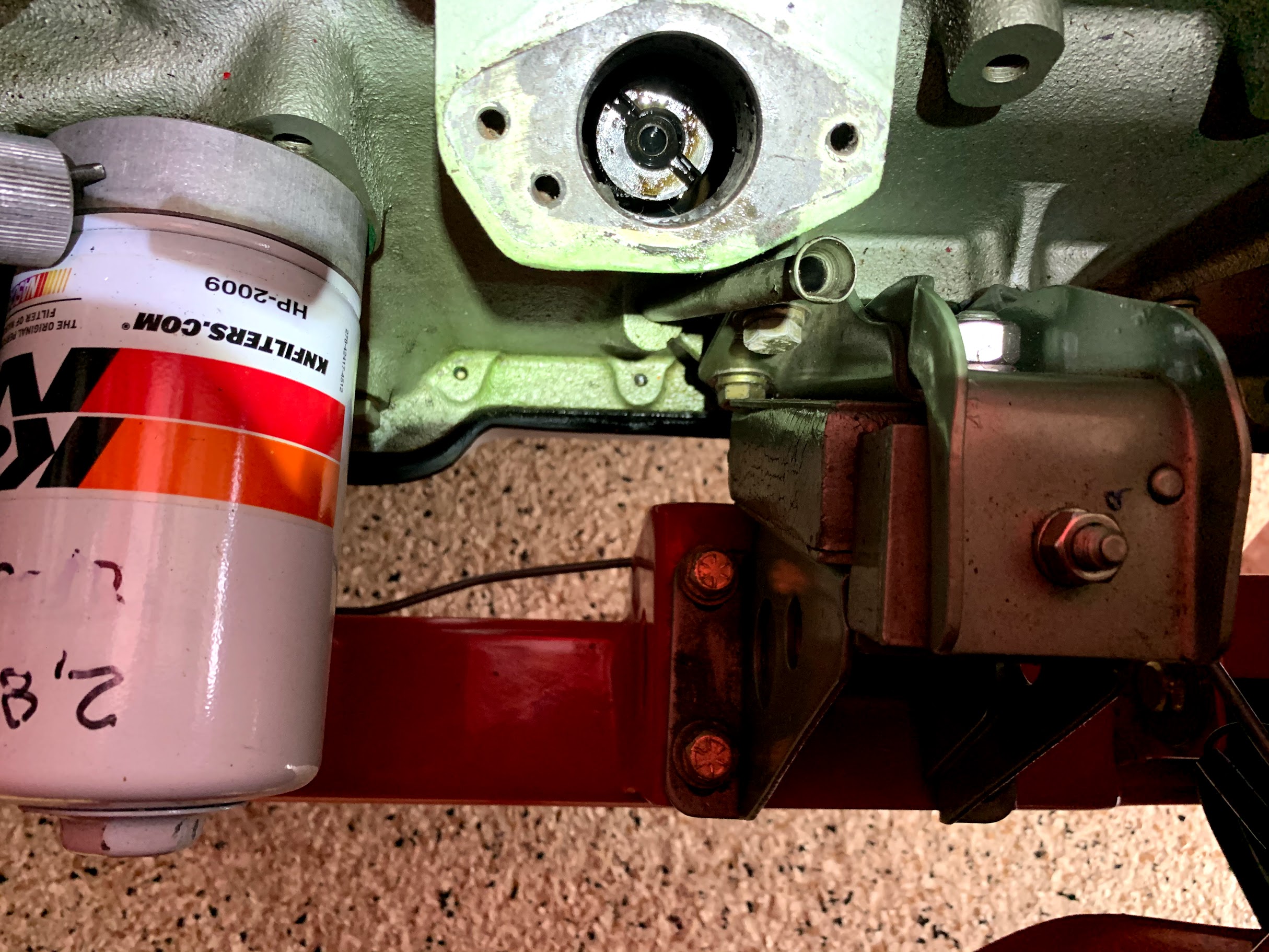
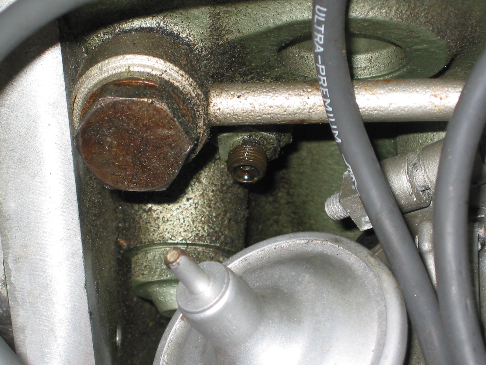
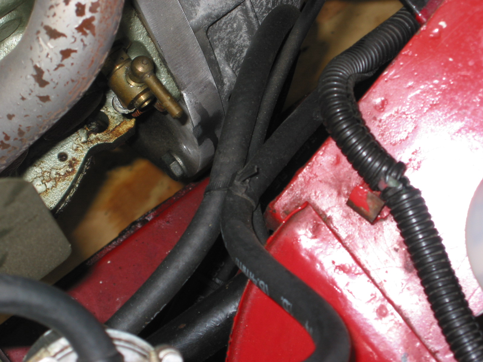
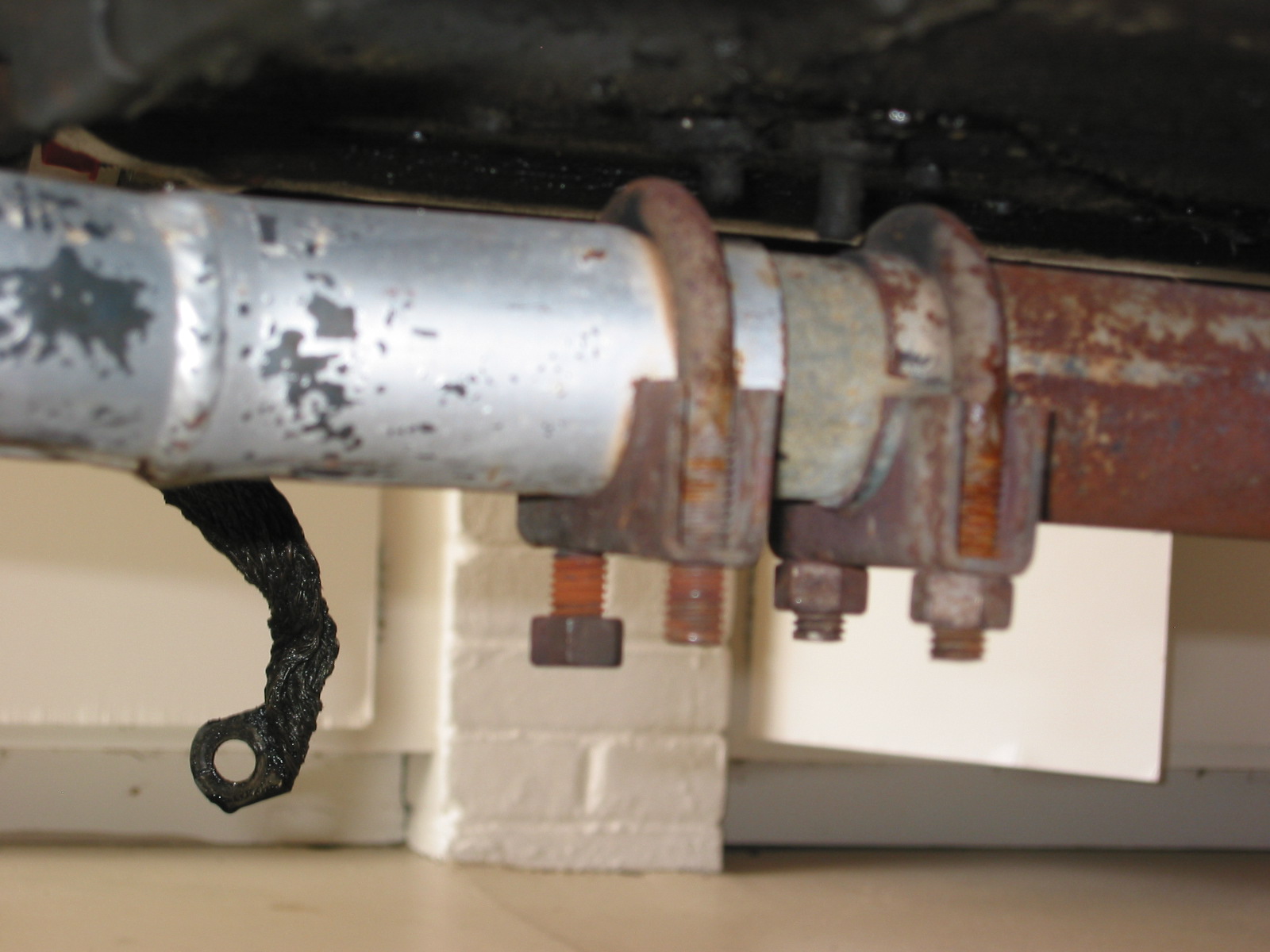
Distributor Drive in the Block
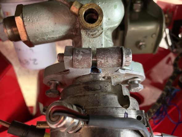
The distributor drive gear is very easy to adjust. Remove the tachometer drive housing by loosening and removing three ¼-28 x ⅞” hex head bolts.
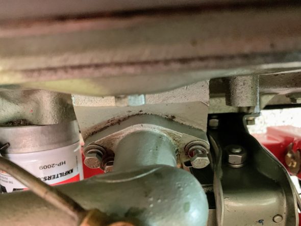
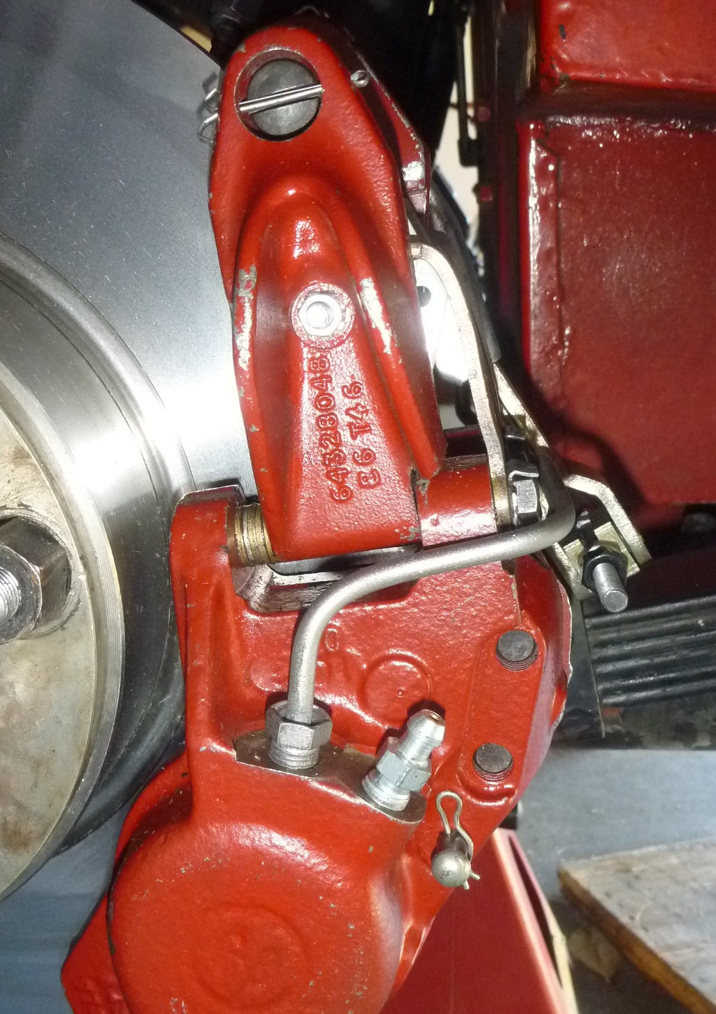
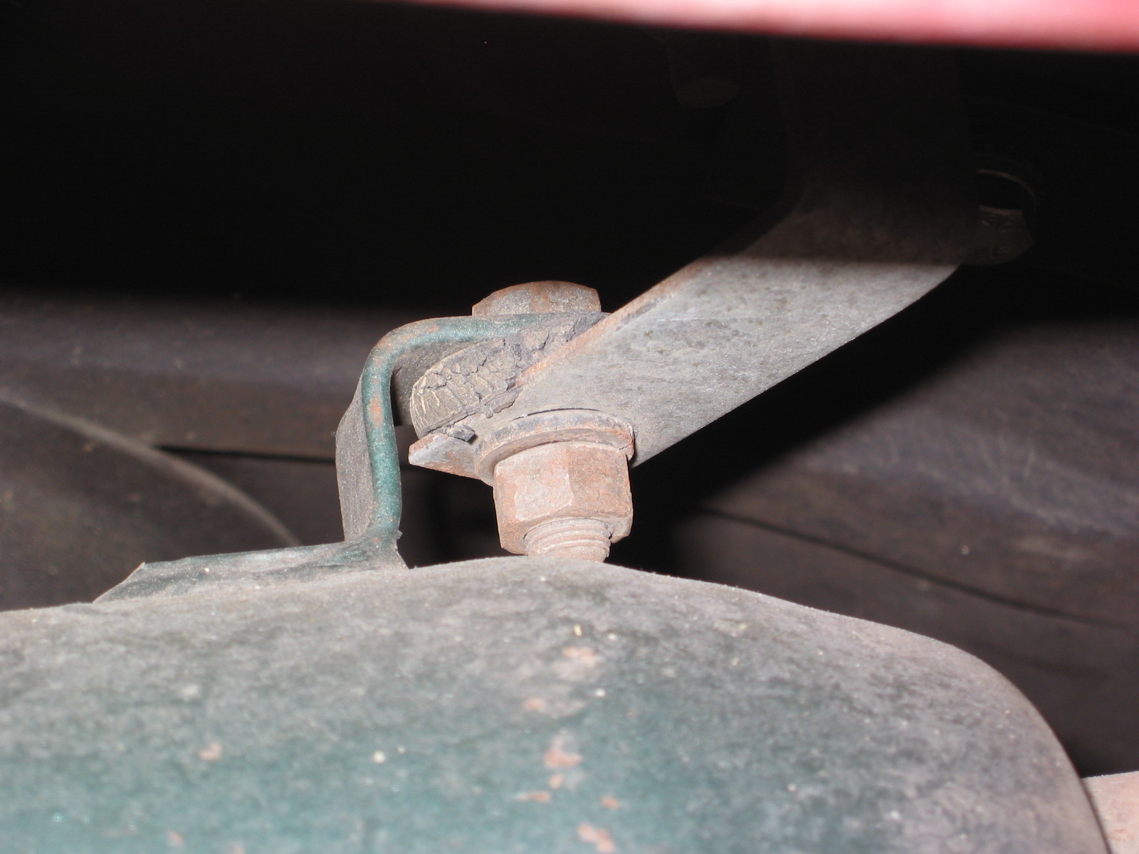
Tachometer Drive Housing Mounting Bolts
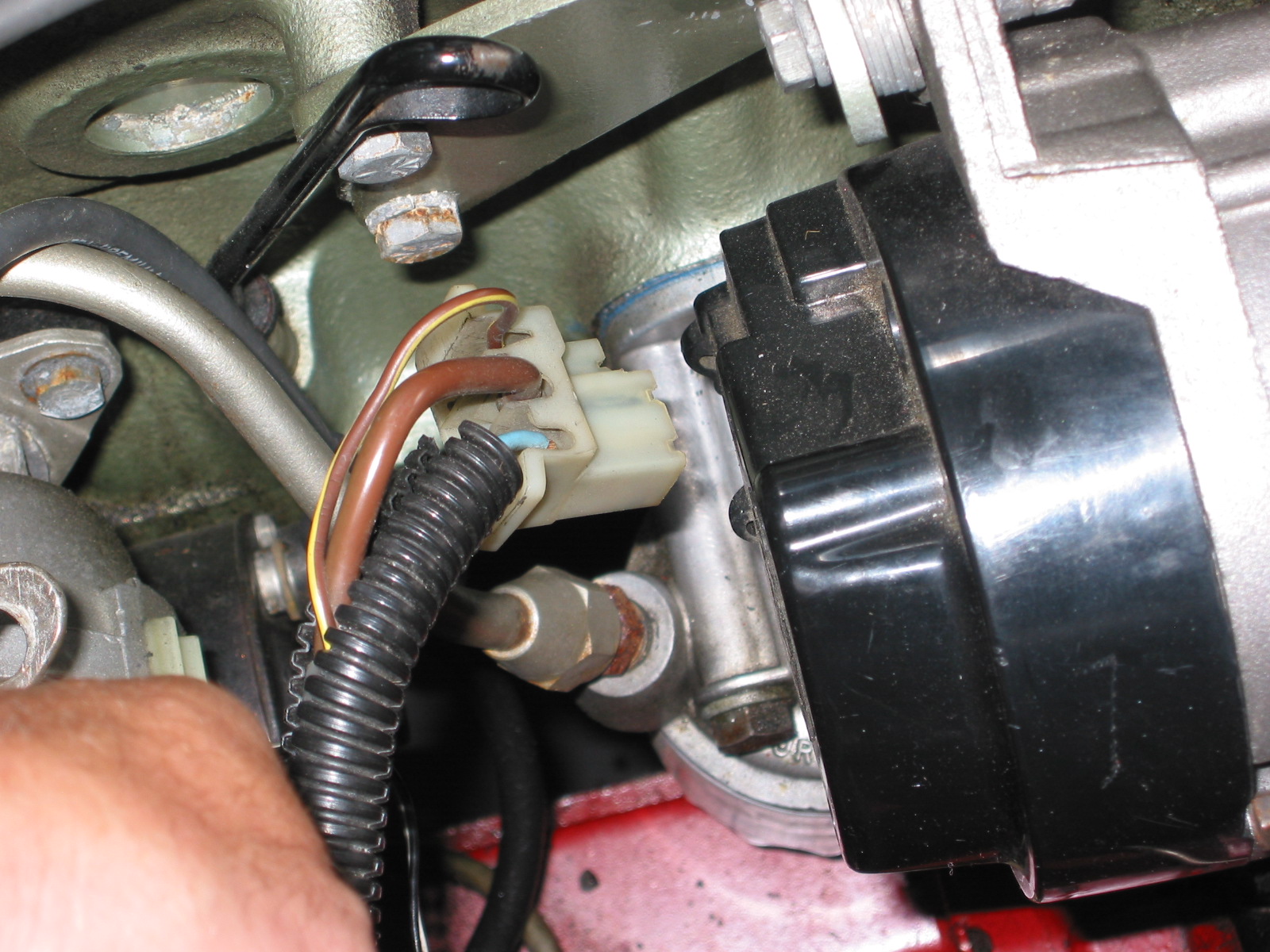
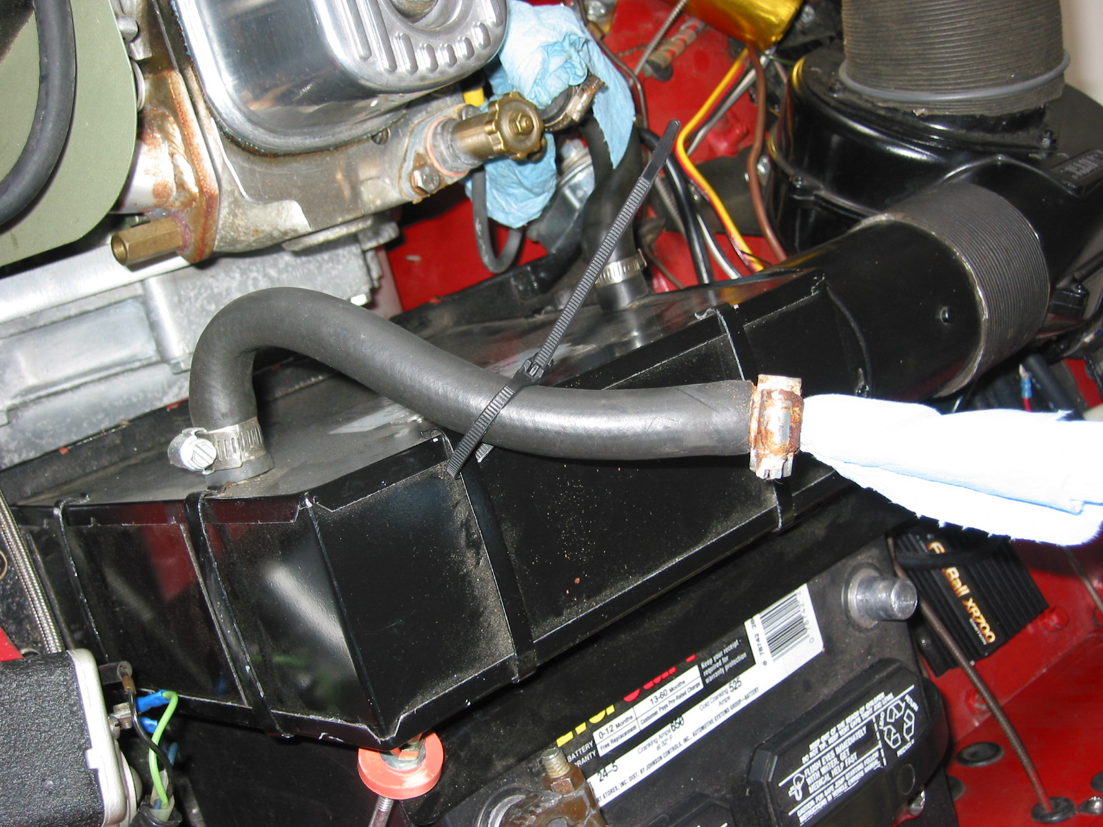
The oil feed banjo and the tachometer cable must be freed from the housing. Then slightly twist and lift away the housing. Then you can give it a fresh coat of paint while it is off the car!
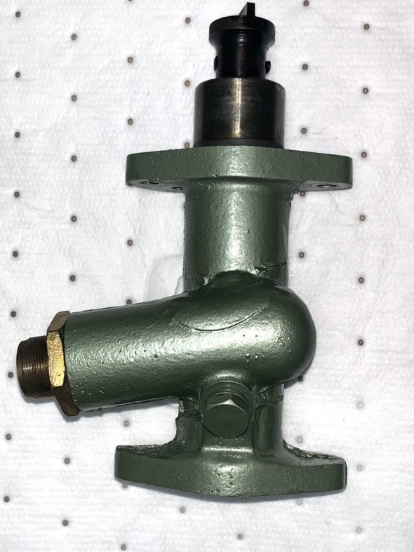
Tachometer Drive Housing
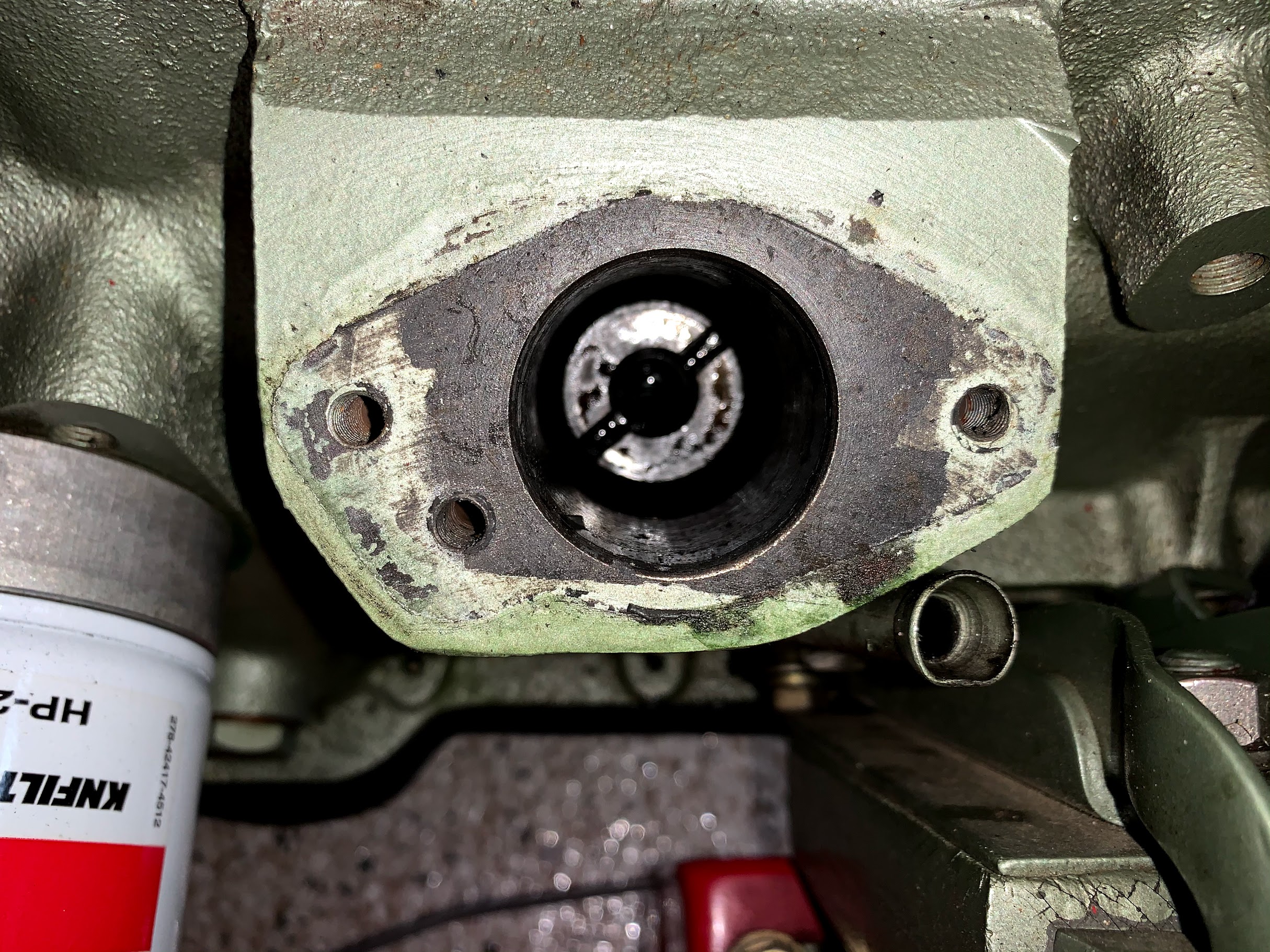
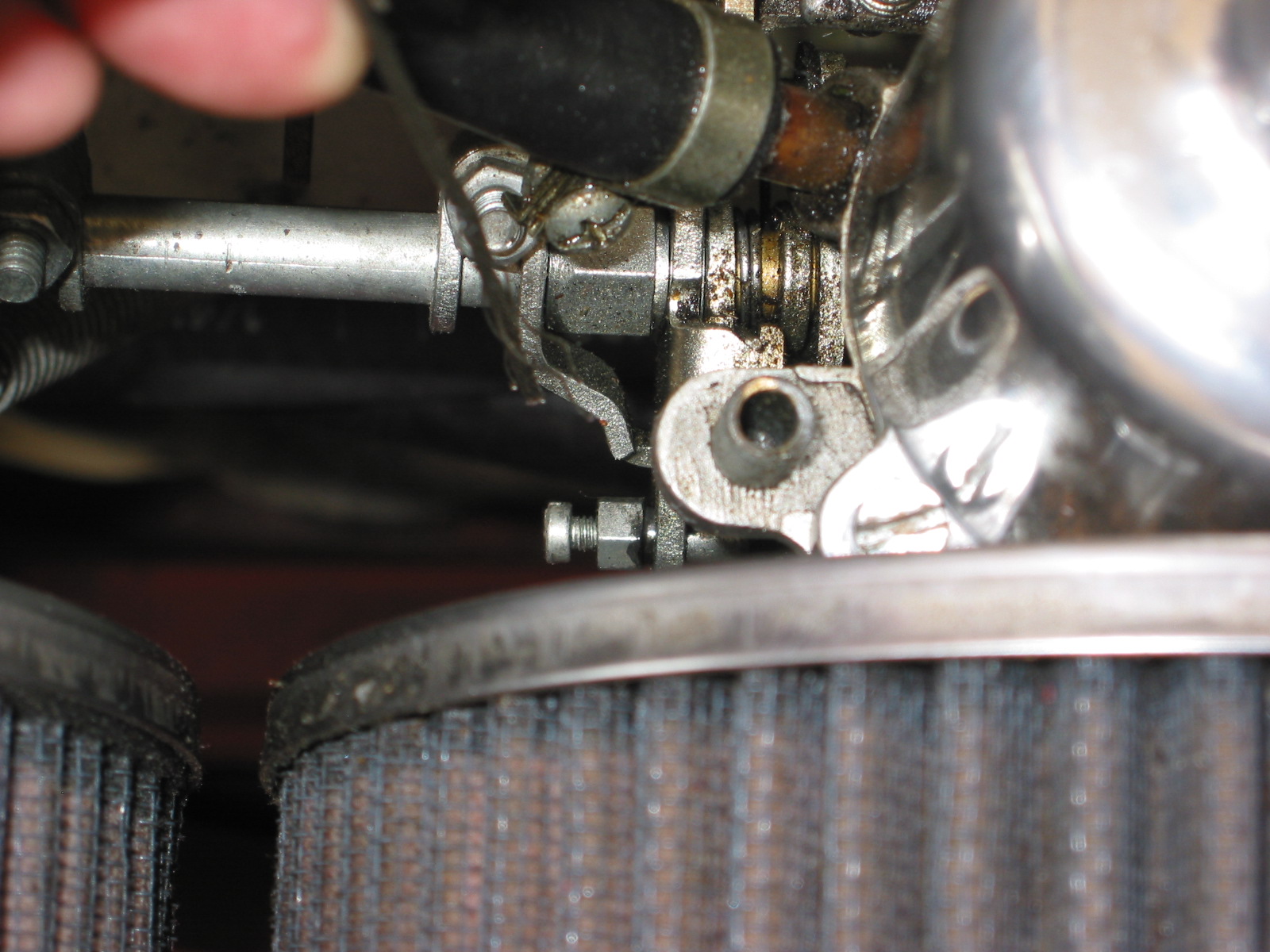
The top of the distributor drive gear is then exposed in its “twenty-to-two” position.

Distributor Drive Gear
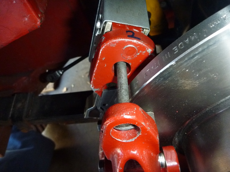
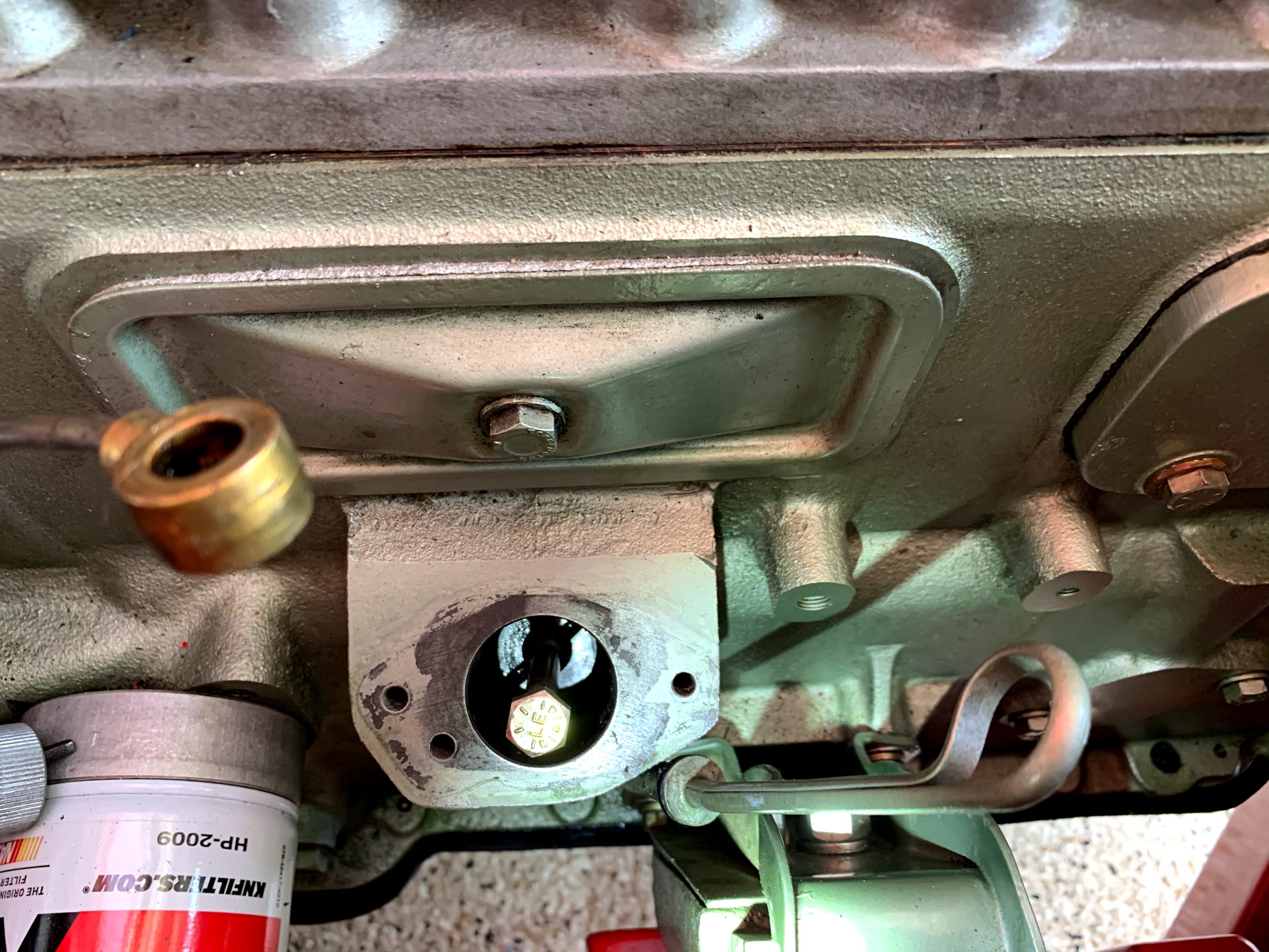
Using a 5/16”- 24 x 3 ½” bolt, screw the bolt in a few turns into the center of the drive gear.

Repositioning the Distributor Drive Gear with Bolt
Lift the bolt and the gear up slightly until you can turn the gear and move it to the “ten-to-five” position. It will drop down into position.

Distributor Drive Gear Repositioned to “Ten-to-Five”
Reassemble everything as it was removed.
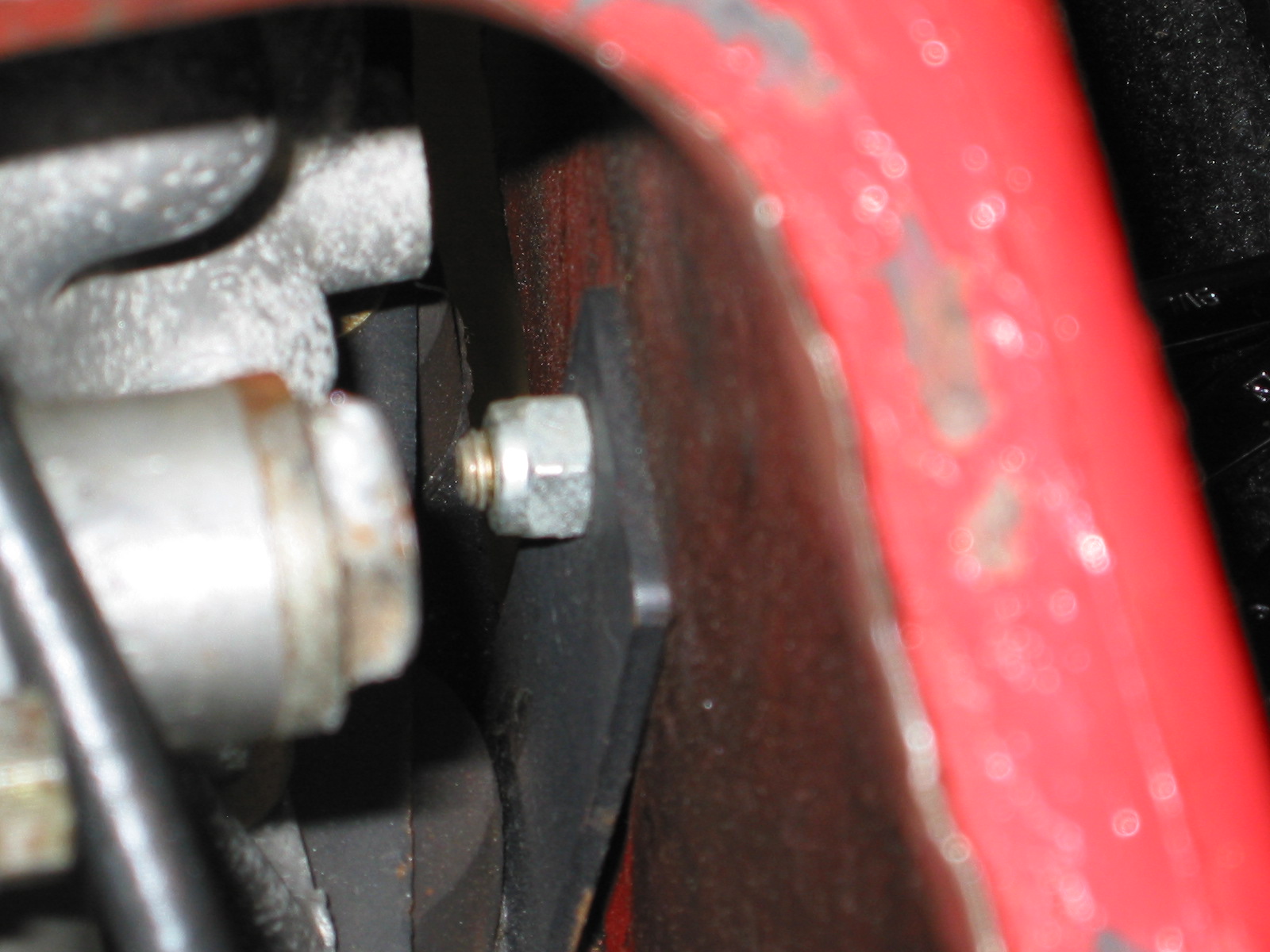
If you happened to have turned the shaft in the housing, when you reinstall it make sure that the tachometer spindle is in the correct position with the smaller segment of the offset dog in the downward position. If it is in the wrong position you will find that the distributor will not seat properly. Reinstall the distributor base plate with two ¼”-28 x ½” hex bolts and the distributor.
Distributor Bse Plate and Mounting Bolts
With the #1 cylinder at top dead center on the compression stroke the 1-2-3 rotor should now be adjusted to be pointing to the #1 cylinder spark plug at approximately the 2 o’clock position.
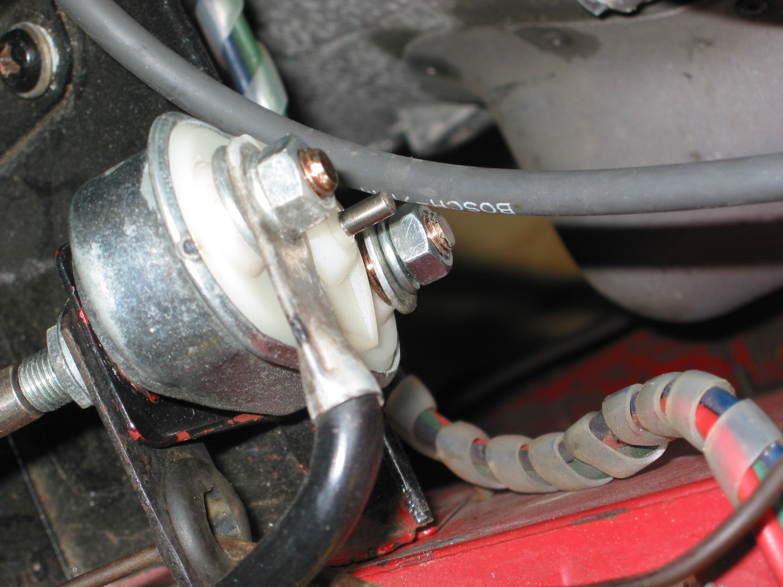
Before placing the cap on the distributor, the 1-2-3 installation instructions state to rotate the distributor body until the distributor wires (black and red) and the vacuum port are in a convenient position for connections. Then connect the red wire to the + terminal on the coil. Leave the black wire disconnected.
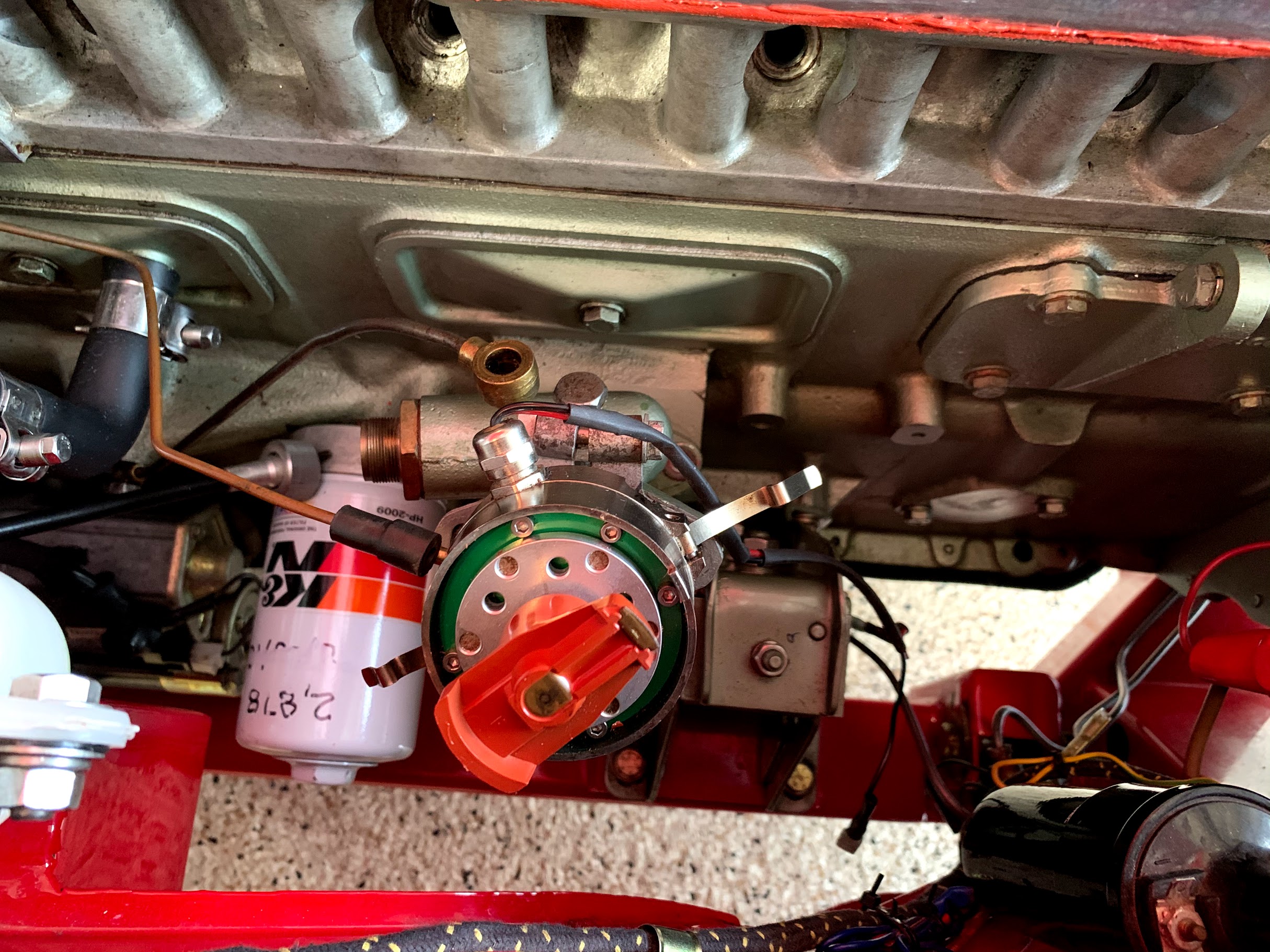
To static time the 1-2-3, turn on the ignition and slowly rotate the body of the distributor and the rotor (to remove any free play) in a clockwise direction until a green LED lights. Then tighten the base plate holding the distributor. Connect the black wire from the distributor to the – terminal on the coil. Attach the ignition wire from the coil to the distributor.

Repositioned Rotor to 2 o’clock
Then install the distributor cap and the ignition wires beginning with the #1 cylinder wire to the distributor cap terminal at the 2 o’clock position (where the rotor is pointed), and then moving counterclockwise connect the other spark plug leads in the prescribed firing order 1-5-3-6-2-4. Attach the ignition cable from the coil to the distributor, and connect the vacuum hose to the distributor. The engine should now start and enable running to get the engine to operating temperature before final ignition timing.
To fine tune the ignition timing with a stroboscope timing light, disconnect the vacuum hose and plug it. Then set your timing in accordance with specifications – in my case, 15 degrees BTDC.
That should do it. I hope this will be helpful to a Healey owner trying a 1-2-3 distributor for the first time.
Prepared by Lin Rose
July 15, 2020