Carburetor Swap to HIF 44

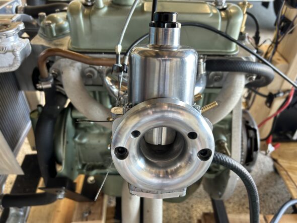
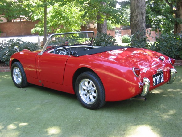
The Bugeye originally had 1 1/4″ twin SU carburetors. We upgraded to twin 1 1/2″ HS2 carbs shortly after purchasing the car. With the current restoration we are going to try a single 1 3/4″ HIF44 carb. We hope to attain equal performance without the need to balance twin carbs. The single HIF carb was routinely used on Minis with essentially the same engine. The HIF 44 is SU’s most modern carb of the period. The float bowl is integrated into the bottom of the carb body rather than a separate float bowl as with the HS2s. 

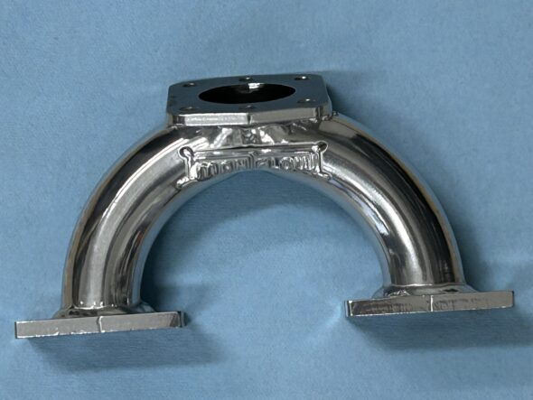
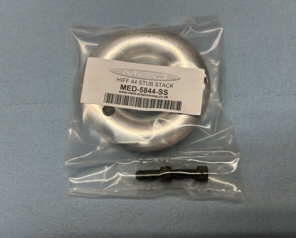
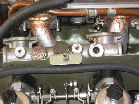
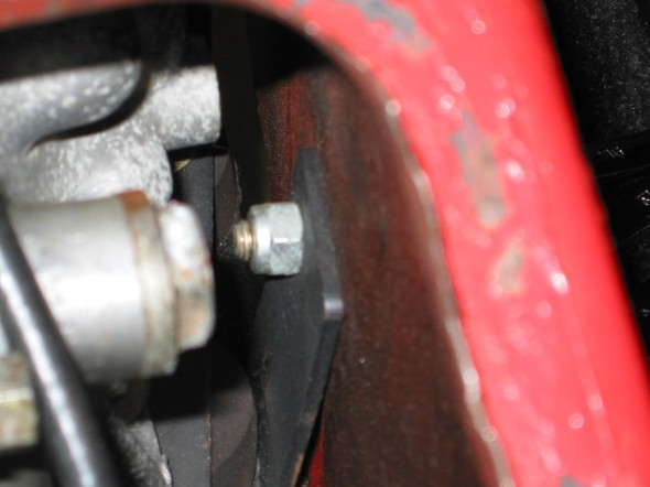
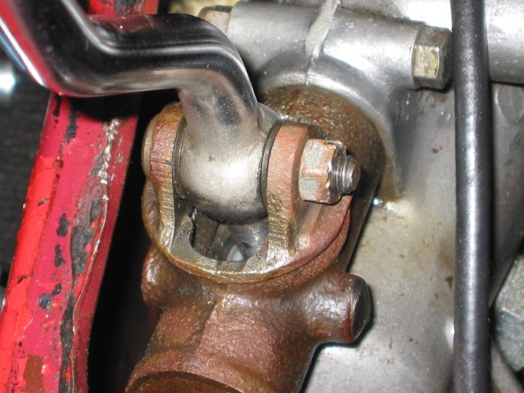
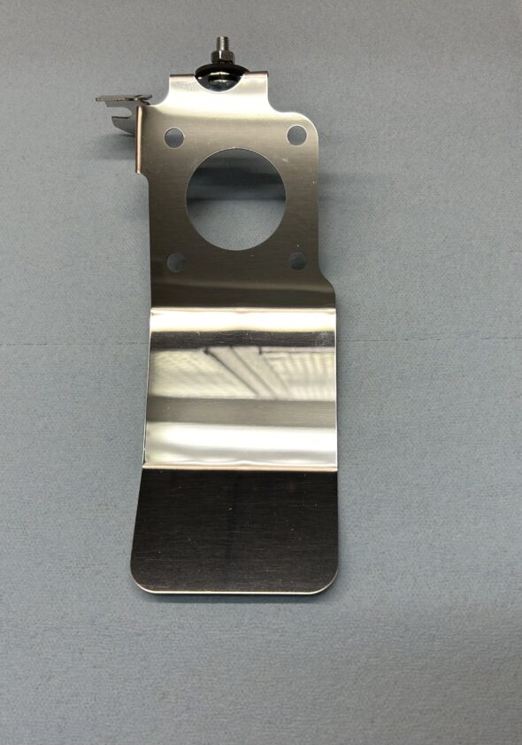
Using the HIF carb requires the use of an appropriate heat shield with integrated securing points for the throttle and choke cables as well as a custom intake manifold sourced from Manifold in the UK. This manifold lowers the carb so that it will not foul against the bonnet.

HIF 44 Heat Shield

Maniflow 1 3/4″ Intake Manifold Jet-Hot Coated

After purchasing the HIF44 we sent it to A.C. Dodd in the UK to have him modify it slightly. The biggest change was converting the unit from manifold vacuum to ported vacuum. Bugeye Restoration Video Episode Fifty-nine reviews the features of the HIF 44 and explains the modifications made to it by A.C. Dodd to prepare it for use in the Bugeye.

https://vimeo.com/924772088/d53a91b278?share=copy

Episode Fifty-nine includes the following content:

0:05 – HIF 44 carb documentation

0:45 – Applications of the HIF 44 carb in other cars

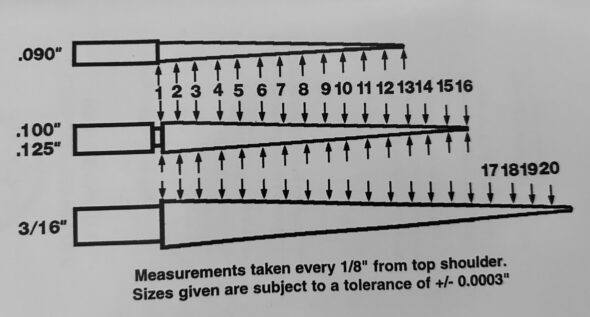
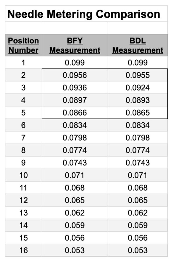
1:37 – HIF 44 carb needle

2:20 – Manifold and Ported vacuum

2:26 – HIF 44 Carb heat shield

2:32 – Maniflow intake manifold

2:50 – Choke cable retaining clip

3:23 – A.C. Dodd HIF 44 modifications

5:33 – HIF 44 Hose fitting legend

5:39 – HIF 44 Throttle and choke cable connections 

Setting up the HIF 44 for initial running is really quite simple. (more info to follow shortly!)

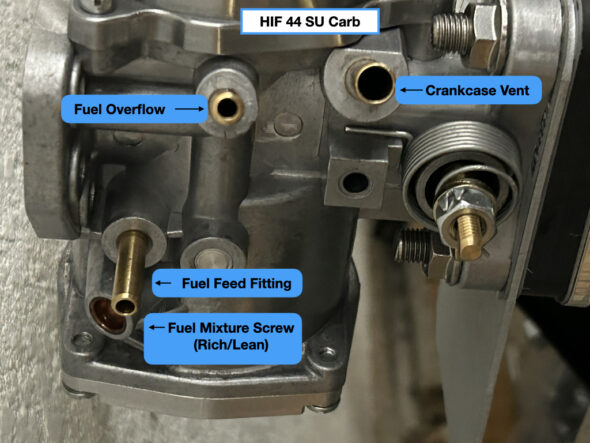
HIF 44 Carburetor (RH Side)

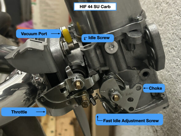
HIF 44 Carburetor (LH side)

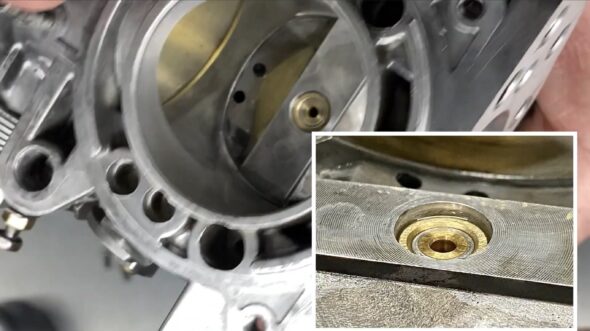
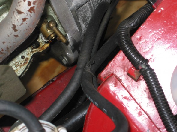
Setting the fuel mixture is the first step. This is accomplished by turning the fuel mixture screw shown in the image above. The image below shows the proper level of the jet:

HIF 44 Proper Jet Height for Start-up

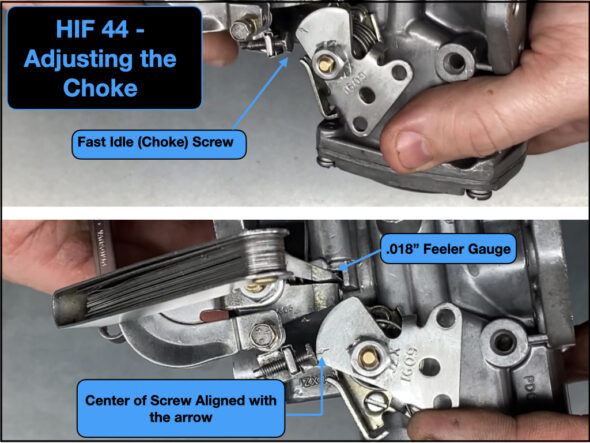
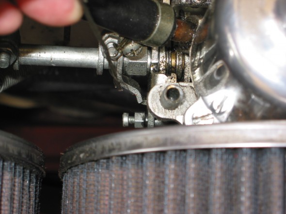
The fast idle, or choke, is set by adjusting the fast idle screw against the cam. The images below show the proper setting. A feeler gauge with .018 blades is used to set the mechanism and then the screw is turned out until it just touches the cam at the arrow.

HIF 44 Adjusting the Choke

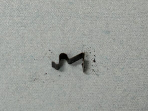
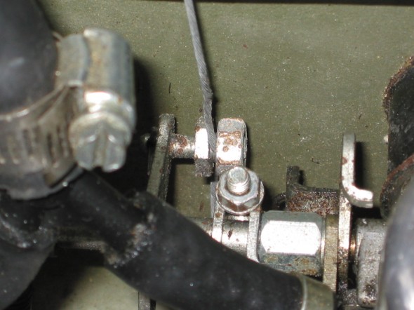
A small spring clip is used to secure the choke cable end fitting to the heat shield choke bracket. It is a friction fit and is just pressed down over the end of the cable ferrule.

HIF 44 Choke Cable Clip

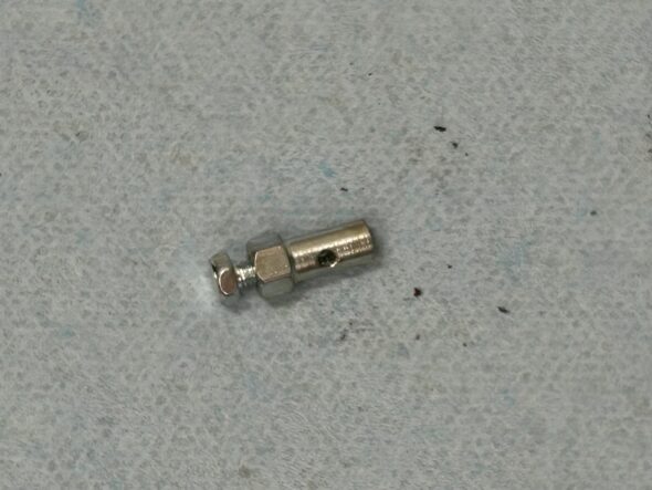
A two piece cable stop is used to secure the choke cable to the choke lever:

HIF 44 Choke Cable Stop

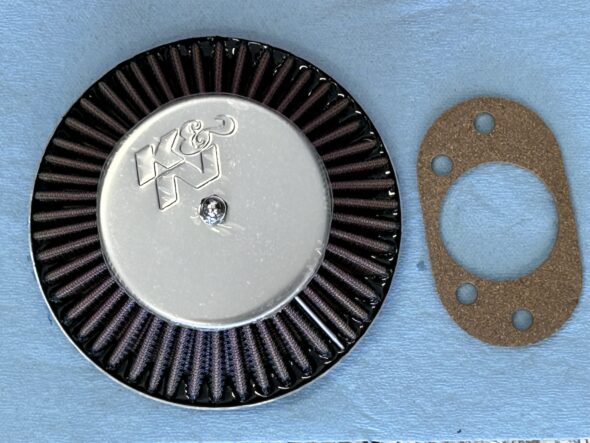
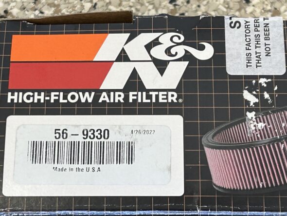
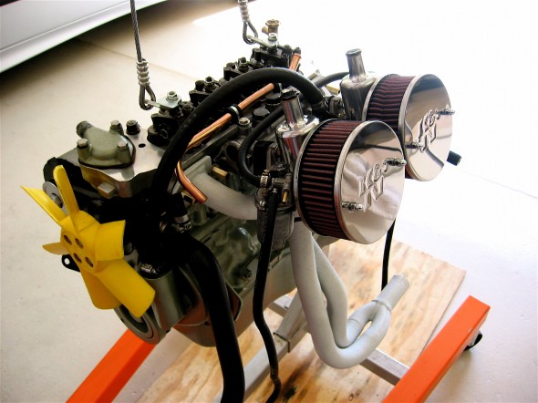
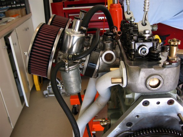
 Finally, we are using a K&N Cone-type air filter for the carburetor. We sourced this one from Moss Motors:

K&N Air Filter

K&N Filter Packaging


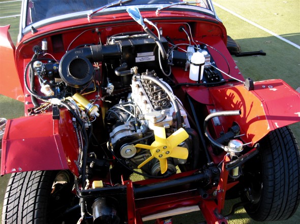
Engine Clean-up and Reinstall

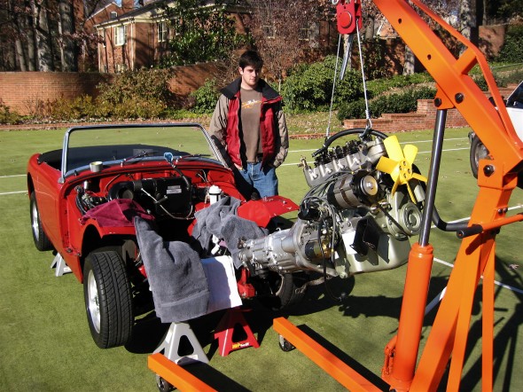
Engine Install

Engine Install

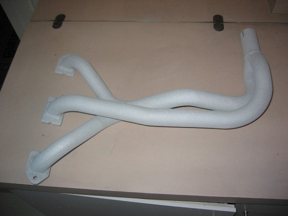
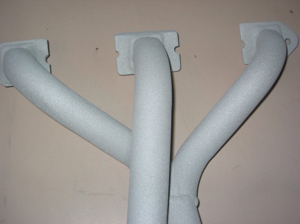
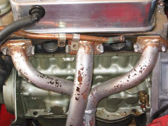
One of the things I wanted to accomplish with the engine clean-up was to have the  exhaust header coated to reduce heat in the engine compartment and interior. I used Swain Coatings. The header came back looking great. Time will tell if the coating holds up and is effective in reducing heat.

Swain Coat Header

Swain Coat Header

Swain Coat Header

Swain Coat Header

I also did a general cleaning of the engine including a new paint job while the gearbox was being worked on by Jack Harper. I replaced the oil sump gasket and the rocker cover gasket, too. I tested and reinstalled the gear reduction starter. The air cleaners were cleaned and oiled with K&N products.

Clean Motor Assembly

Clean Motor Assembly

Clean Motor Assembly

Clean Motor Assembly

I developed the following list of items for reinstalling the engine and gearbox into the Bugeye:
Reinstalling a Bugeye Engine and Datsun 5-speed Transmission

  1. Grease the shaft splines on the engine and the yoke before installing the engine.
  2. Set the exhaust header in place so that it will be positioned to install once the engine is tightened into its mounts.
  3. Guide the motor into place with the lift so that the yoke on the driveshaft lines up with the transmission. If this does not work then remove the driveshaft and install after the engine and transmission are in place.
  4. Loosely secure the engine to the front motor mounts. The mounts themselves should be loose then tightened after all bolts/nuts are in place.
  5. Install the long bolts up through the crossmember into the rear transmission mount and tighten.
  6. Tighten the front engine mounts.
  7. Center the transmission in the rear mount, then push it as far to the right as possible, and tighten the transmission pad mounts on the bracket.
  8. Install the bolts in the sides of the transmission rear mounts from inside the car with the self locking nuts inside the tunnel. (Hint: tape the nuts in the wrench to make starting the threads easier.)
  9. Replace the gearshift lever.
  10. Connect the ground strap to the frame of the car.
  11. Replace the rocker cover and connect the breather hose.
  12. Install the intake and exhaust manifolds.
  13. Install heat shield and carbs.
  14. Connect throttle and choke cables.
  15. Connect breather hose.
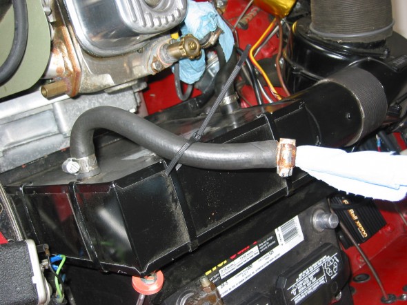
  16. Connect hot water hose to copper tube and connect to radiator hose. Tighten clamps. It is easier to put the clamp on the hose/copper pipe when the copper pipe clips are loose from the manifold.
  17. Connect the short hot water hose from the water control valve to the heater.
  18. Connect the electrical cable from the gear reduction starter to the starter solenoid.
  19. Connect the oil pressure pipe to the fitting on the engine block by the banjo bolt.
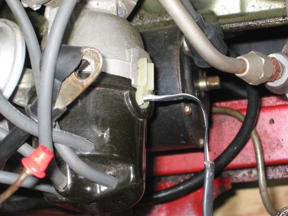
  20. Reconnect the white/black line from the electronic ignition to the distributor.
  21. Connect the high tension line from the distributor to the coil.
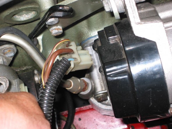
  22. Reconnect the plastic terminal (3 wires) to the alternator.
  23. Connect the fuel line from the fuel pump to the carbs.
  24. Reattach the water temperature sensor to the engine head.
  25. Remove the banjo bolt where the oil line exits the rear of the block. Pour motor oil down the hole in the block to prime the oil pump. Reinstall the bolt.
  26. Remove the oil filter and pour it full of motor oil and reinstall.
  27. Fill engine with oil – Castrol GTX 10W-40.
  28. Fill the gearbox with Gear lube – Redline MT90. 2 1/4 pints. Use long clear plastic tube. Try pump.
  29. Connect the stainless steel flex line from the master cylinder to the slave cylinder.
  30. Bleed the clutch slave cylinder. (See Page 9 of Rivergate’s manual)
  31. Install radiator and fill with 50% coolant and 50% distilled water.
  32. Fix the carb drain lines to the mounting clamp at the lower rear of the engine compartment.
  33. Insert the 1 ½” connecter pipe (with sealant) for the exhaust system into the header pipe.
  34. Install the exhaust and muffler assembly.
  35. Tighten clamps on the exhaust connecter pipe.
  36. Reconnect the battery cables.
  37. When ready to start the engine, pull the spark plugs and spin the engine with the starter until the oil pressure goes up to normal on the pressure gauge, and stays.
  38. Check for any oil, coolant and fuel leaks.
  39. Reinstall the spark plugs and start engine.
  40. If engine does not start turn distributor 180 and try again!
  41. Install 4” fresh air heater hose and clamp.
  42. Install the leather shifter cover and surround.

Start It Up And Have Some Fun!

I Know It Fits!

I Know It Fits!

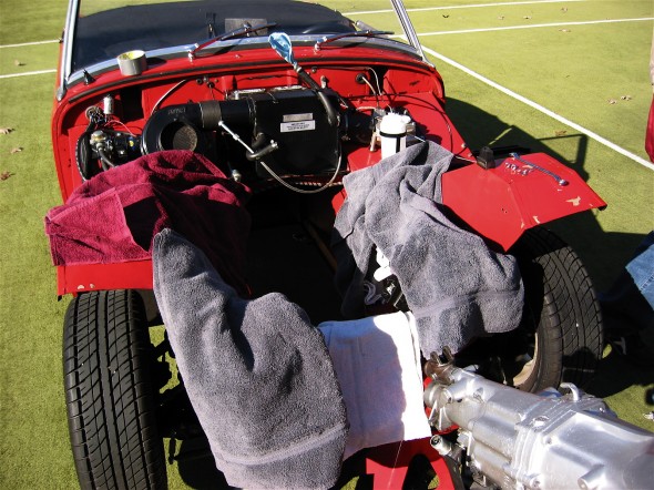
Motor Protection!

Motor Protection!


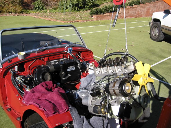
Engine Install

Engine Install

Pulling the Engine for Minor Repairs

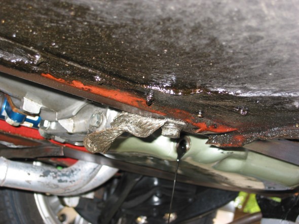
July 2006 Bugeye It is time to fix some of the problems we have lived with for a while and to make a few improvements. The oil leak we caused when we failed to seal the oil sump properly, the gear grinding in 2nd and 3rdin the gearbox, jet coating the headers among other things will improve the car for the future. These improvements require pulling the engine. We bought a cherry picker and an Oberg tilt lift rather than continuing to rent at $45 a pop. The following details the process to get ready to lift out the engine: Disconnected the battery positive lead from the terminal. Drained the engine oil, tried the gearbox, but couldn’t get the plug out so will return to that. Disconnected the ground strap and removed the two gearbox mounting bolts from the bottom of the car.

ground strap

Ground Strap

Gearbox Mount Bolts

Gearbox Mount Bolts

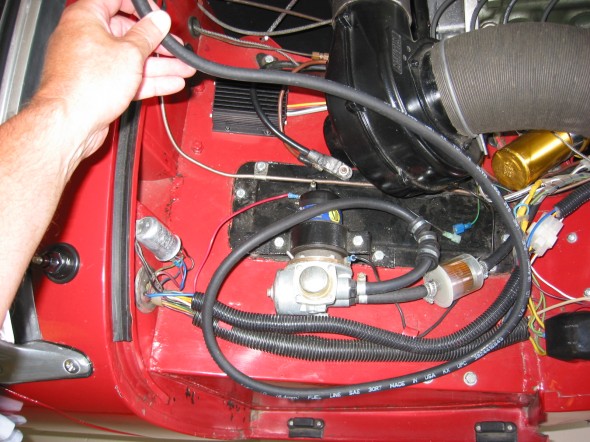
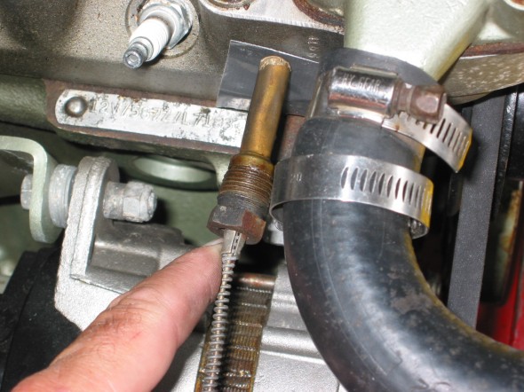
Disconnected the fuel line at the carbs and pulled out of the way, and disconnected the temperature sensor from the head.

Fuel Line

Fuel Line

Temperature Sensor

Temperature Sensor

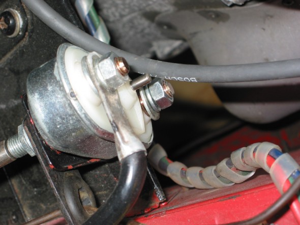
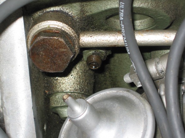
Disconnected the oil pressure gauge line and the oil feed line from the engine block, and disconnected the cable from the starter solenoid to the starter.

Solenoid Connection

Solenoid Connection

Oil Temp Connection

Oil Temp Connection

Unsnapped the plastic connector for the white/black line to the distributor from the electronic ignition device, and disconnected the plastic terminal (3 wires) to the alternator.

Ignition Wiring

Ignition Wiring

Alternator Wiring

Alternator Wiring

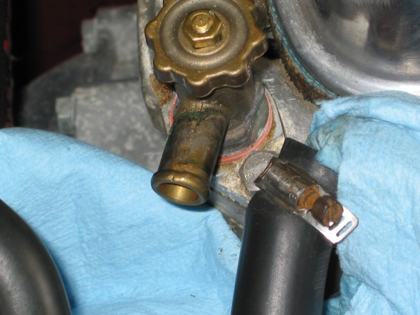
Disconnected the high tension line from the distributor to the coil. Disconnected the short hot water hose from the hot water valve control on the head and then the longer line on the other side of the engine to the copper tube. It is easier to put the clamp on the hose/copper pipe when the copper pipe clips are loose from the manifold.

Water Valve

Water Valve

Heater Hose

Heater Hose

Disconnected the throttle cable at the carb linkage and pulled it out of the way, and then also disconnected the choke cable at the carb.

Throttle Cable

Throttle Cable

Choke Connection

Choke Connection

Disconnected the fitting at the slave cylinder (and got brake fluid everywhere).

Fuel Drain Line

Fuel Drain Line


Intake Manifold

Intake Manifold


Very Ugly Header

Very Ugly Header

Removed the manifold brass nuts from the head and lifted the intake manifold and carbs free of the engine. The carb drain lines tied together with plastic straps will need to be rerouted to the retainer clips upon installation again. The headers will not come out of the engine bay until the engine is pulled or the heater is removed. Need to set the headers in place prior to the engine install.

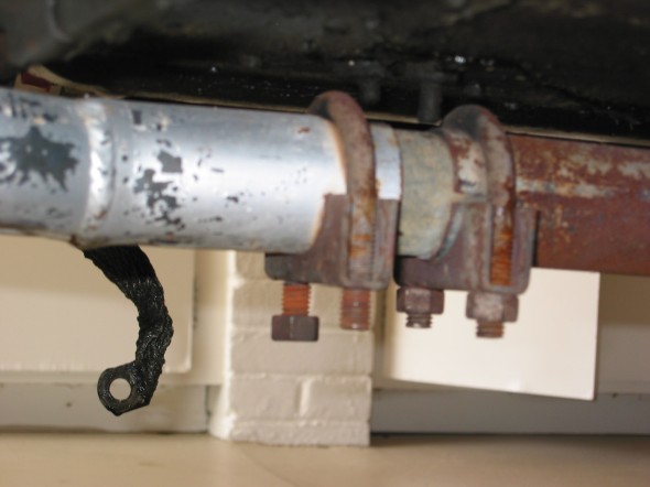
Exhaust Clamps

Exhaust Clamps

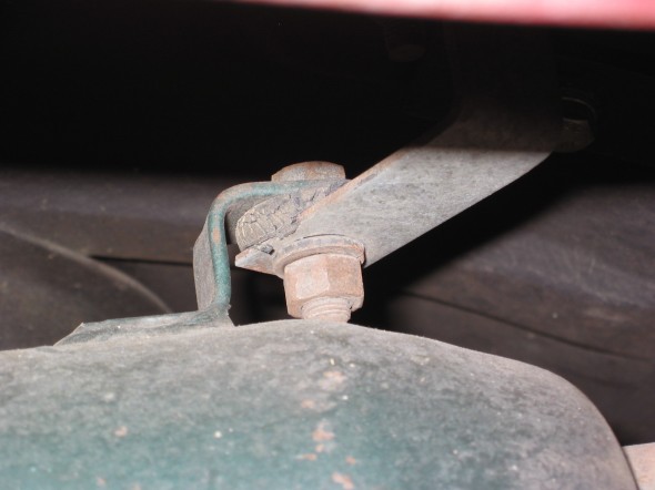
Exhaust Mount

Exhaust Mount


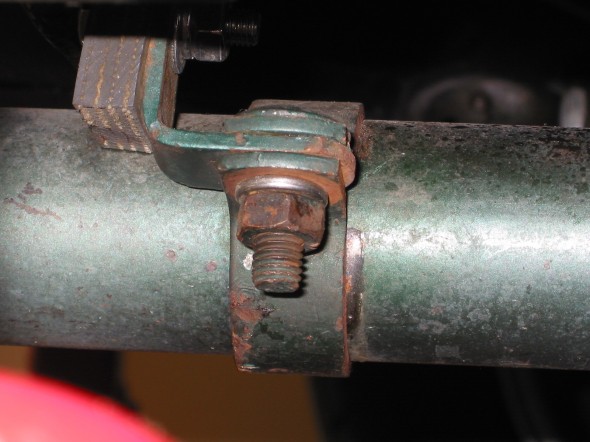
Exhaust Clamp

Exhaust Clamp

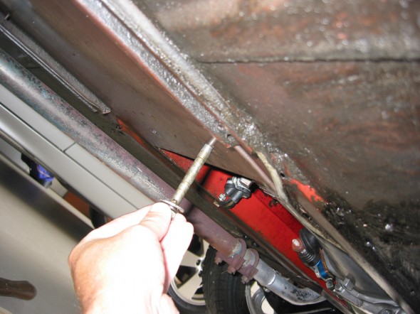
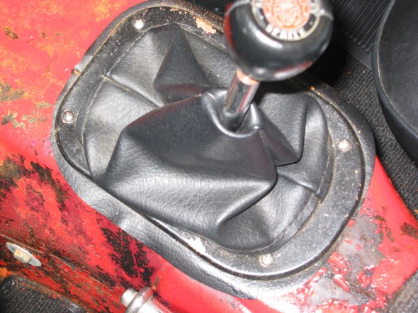
Removed four Phillips screws attaching the shift boot to the gearbox tunnel, the shifter knob, and removed two bolts on each side of the tunnel securing the gearbox bracket to the car. Use of the offset wrench made this an easier job.

Shifter Trim Ring

Shifter Trim Ring

Gearbox Rear Mount

Gearbox Rear Mount


Shifter Connection

Shifter Connection

Loosened the right hand motor mount from the car so that it will lift free with the engine, but will not completely disconnect until the engine lift has the pressure off of the mounts. Loosened the screws to the engine at the mount on the left side of the car. The left mount will stay in the car.

Removed the cardboard heater hose to have it out of the way from the engine when it is lifted.

Connected the Lift Chain to the Rocker Shaft mounting studs and lifted the engine from the car.