Carburetor Swap to HIF 44

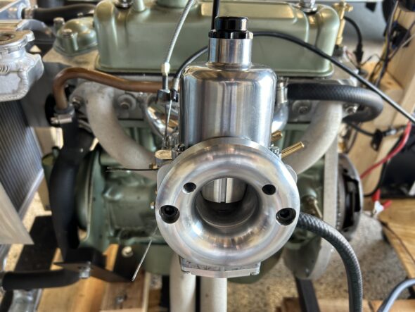
The Bugeye originally had 1 1/4″ twin SU carburetors. We upgraded to twin 1 1/2″ HS2 carbs shortly after purchasing the car. With the current restoration we are going to try a single 1 3/4″ HIF44 carb. We hope to attain equal performance without the need to balance twin carbs. The single HIF carb was routinely used on Minis with essentially the same engine. The HIF 44 is SU’s most modern carb of the period. The float bowl is integrated into the bottom of the carb body rather than a separate float bowl as with the HS2s. 

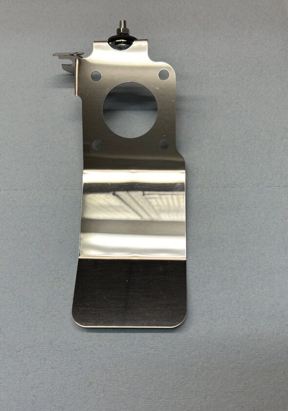
Using the HIF carb requires the use of an appropriate heat shield with integrated securing points for the throttle and choke cables. I ordered this one https://www.ebay.com/itm/163969687994  not only is it polished stainless, it also provides an angled extension under the bottom of the carb (where the float bowl is located) to provide a little extra heat protection. This is a very nice piece.

Modified stainless HIF 44 Heat Shield

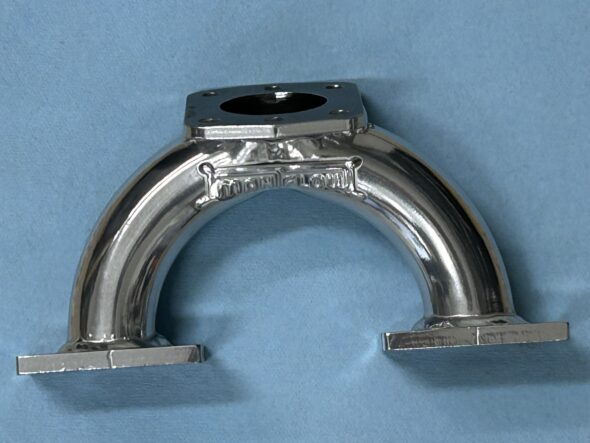
 A custom intake manifold is also required on the Bugeye. Sourced from Maniflow in the UK. This manifold lowers the carb so that it will not foul against the bonnet.

Maniflow 1 3/4″ Intake Manifold Jet-Hot Coated

After purchasing the HIF44 we sent it to A.C. Dodd in the UK to have him modify it slightly. The biggest change was converting the unit from manifold vacuum to ported vacuum. Bugeye Restoration Video Episode Fifty-nine reviews the features of the HIF 44 and explains the modifications made to it by A.C. Dodd to prepare it for use in the Bugeye.

https://vimeo.com/924772088/d53a91b278?share=copy

Episode Fifty-nine includes the following content:

0:05 – HIF 44 carb documentation

0:45 – Applications of the HIF 44 carb in other cars

1:37 – HIF 44 carb needle

2:20 – Manifold and Ported vacuum

2:26 – HIF 44 Carb heat shield

2:32 – Maniflow intake manifold

2:50 – Choke cable retaining clip

3:23 – A.C. Dodd HIF 44 modifications

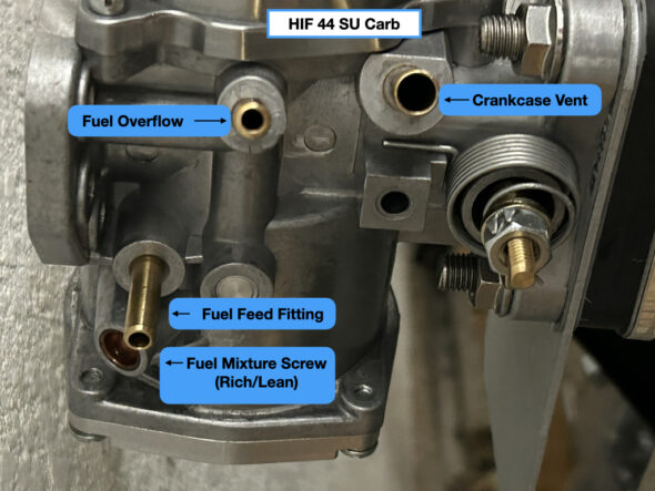
5:33 – HIF 44 Hose fitting legend

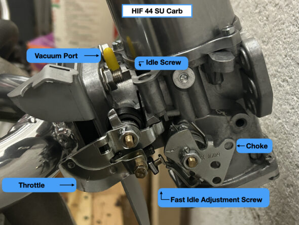
5:39 – HIF 44 Throttle and choke cable connections 

Setting up the HIF 44 for initial running is really quite simple. (more info to follow shortly!)

HIF 44 Carburetor (RH Side)

HIF 44 Carburetor (LH side)

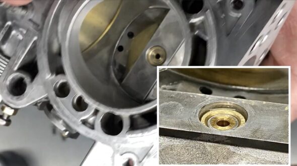
Setting the fuel mixture is the first step. This is accomplished by turning the fuel mixture screw shown in the image above. The image below shows the proper level of the jet:

HIF 44 Proper Jet Height for Start-up

Turning the adjustment screw to the left will lean out the mixture by raising the jet thereby letting less fuel enter the manifold. Turning it to the right will enrich the mixture. This screw should only be adjusted to effect a change in the idle. It should not be adjusted  to improve the drivability of the car at speed.

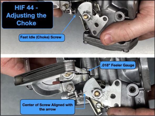
The fast idle, or choke, is set by adjusting the fast idle screw against the cam. The images below show the proper setting. The fast idea screw is turned down until it just touches the throttle lever. Once in that position it can be turned down one full turn. A feeler gauge with .018 blades is then inserted between the fast idle screw and the throttle lever. The choke lever is then rotated to line up with the center of the throttle adjusting screw. This is achieved by turning the adjusting screw until it just touches the arrow.

HIF 44 Adjusting the Choke

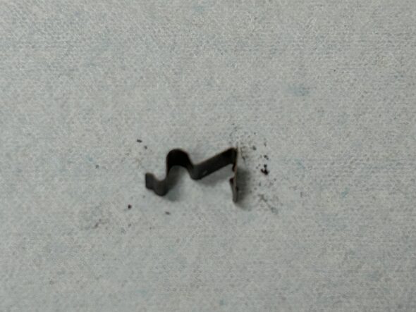
A small spring clip is used to secure the choke cable end fitting to the heat shield choke bracket. It is a friction fit and is just pressed down over the end of the cable ferrule.

HIF 44 Choke Cable Clip

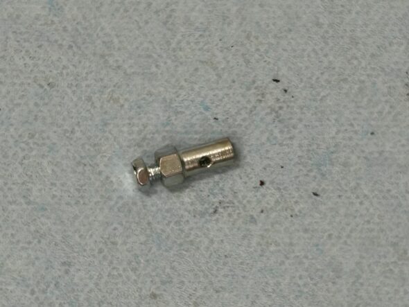
A two piece cable stop is used to secure the choke cable to the choke lever:

HIF 44 Choke Cable Stop

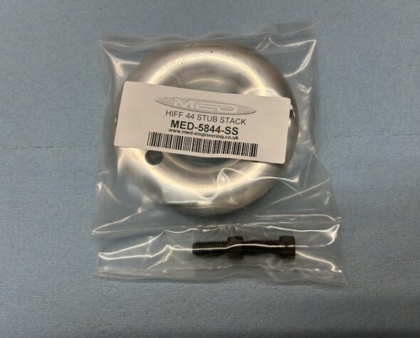
 We also decided to improve air flow into the carb by installing an aluminum stub stack sourced from M.E.D. Engineering in the UK.

MED Stub Stack

Their site describes the billet stub stack this way:

The MED aluminum stub stacks have been extensively tested on our 110 Superflow flow bench to optimise the elliptical radius on the stub stack. The result is improved air flow to the carburettor/throttle body and a proven increase in performance – on a wide range of different engines and rolling roads.

The stub stack is temporarily mounted in this photo. Eventually the K&N air filter back plate will be installed first with the stub stack mounted inside the filter assembly.

Stub stack temporary installation

Much of the tuning of the HIF 44 carb is accomplished through needle adjustment, spring choice and variations in damper oil weight. Our carb came with a BFY spring loaded needle. Upon initial running (but before we have connected an AFR gauge) the engine seemed to run well at higher rpm but lugged a bit at idle and required the use of the choke for longer than expected. We wondered if the BFY needle was the cause of insufficient fueling at idle, so we decided to try a BDL needle. 

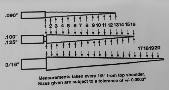
The .100″ jet needles (the middle needle below) are measured in 16 increments:

Needle Metering Increments

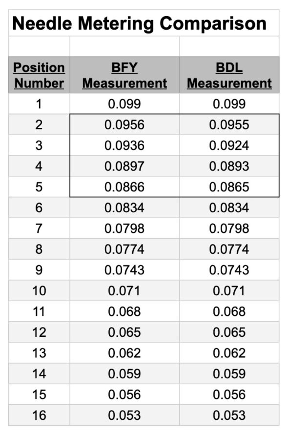
The following chart depicts the difference between the BFY Needle and the BDL Needle. As can be seen, the needles are very similar. The only differences are in positions 2,3,4 and 5. This should leave us with a slightly richer condition at idle and maintain the same fuel condition in the higher rpm range. Hopefully we will not need as much choke this time. Additional running will tell us if we have improved our running at idle or not.

BFY and BDL Needle Comparison

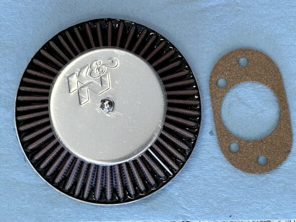
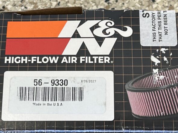
Finally, we are using a K&N Cone-type air filter for the carburetor. We sourced this one from Moss Motors:

K&N Air Filter

K&N Filter Packaging


Bloody Beast Maintenance

Maintenance

October, 2014 – 

Returning home from the Shenandoah Valley British Car Club show in Waynesboro, VA I noticed that the clutch pedal was slippery. Sure enough the seals in the master cylinder failed and I had some nasty brake fluid leaking from the cylinder. I removed both the brake and clutch masters figuring that I might as well rebuild them both at the same time. Both were brand new when installed in the car, so other than cleaning the bores I did not bother with a full rebuild including honing or lining the bores. I have fewer than 12,000 miles on the originals, but it has been five or six years and who know how long they were on the shelf before I installed them?

Both of my masters were 5/8″ bores and I decided to purchase a new 3/4″ bore for the brake system. Ordered one from British Parts Northwest.

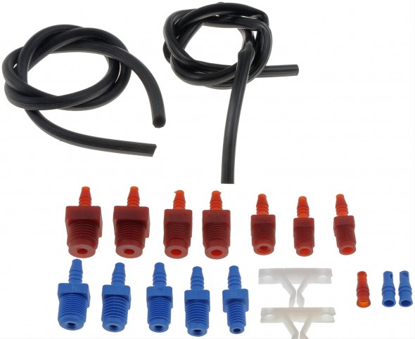
In preparing to bench bleed the two masters I decided to purchase a little “HELP” kit from Summit Racing for all of $6.00. I did substitute clear hose for the black vinyl so that I could observe the air bubbles flowing to the fluid reservoir. The Healey master cylinders use the 3/8″ –  24 and the 7/16″ – 20 fittings, but many others are supplied in the kit.

Dorman Bench Bleeder Kit

Dorman Bench Bleeder Kit

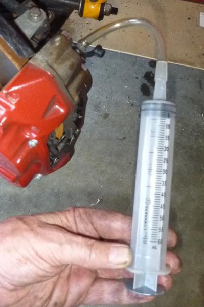
Steve Gerow on the British Car Forum recommended “pulling” the air from the brake calipers rather than pushing the fluid from the reservoir:

“This bleeding syringe worked a charm, obviating the need for bench-bleeding. My Healey-neighbor Dennis Williams suggested packing the area around the nipple with grease to prevent air leakage. You just pull the air out of the system until you’ve got clear, bubble-free juice in the syringe. Keep an eye on the reservoir, of course.”

Cardone Brake Bleeding Syringe

Cardone Brake Bleeding Syringe


Steve often comes up with the innovative ways of approaching maintenance issues so I thought I would give it a try. These are the directions that came with the syringe:

Cardone 10-5000MCB Master Cylinder Bleeder Tool Directions

I was overdue for a complete brake fluid flush so I pumped out all of the old stuff while I was at it.

Motive Power Bleeder

I have had a Motive Power Bleeder http://www.motiveproducts.com for several years and never used it. I ordered the special reservoir cap specified for the Healey – Part number 1100 I believe. It did not fit!

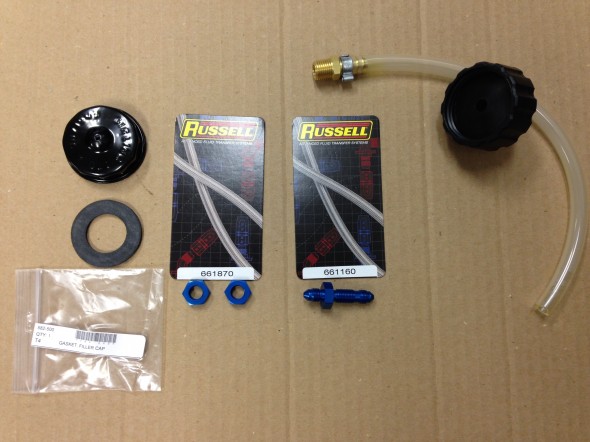
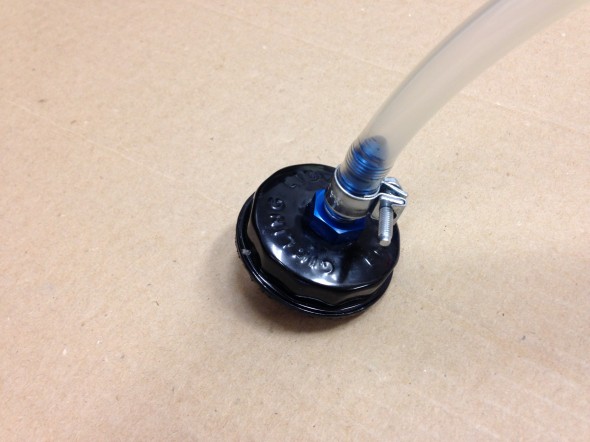
This master cylinder episode got my inspired to solve this little problem. I ordered another master cylinder reservoir cap and seal from Moss Motors. Part numbers 596-210 and 582-500. I then went on a search for a 1/4 brass fitting to install in the cap. The fitting was easy to find but after trying two automotive parts stores, a “they have it all” hardware store and a large plumbing supplier I gave up on finding a nut with the proper pipe thread! Finally, at a local fabrication shop I found these Russell fittings and they worked perfectly. The hose and cap #1100 to the right in the image below were supplied with the Motive Bleeder. I just disconnected the hose from the cap that did not fit.

Reservoir Cap Modification for Motive Bleeder

Reservoir Cap Modification for Motive Bleeder

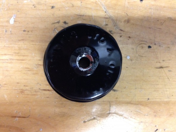
I then drilled a hole in the center of the Healey reservoir cap to tightly fit the Russell hardware. This required flattening the center of the cap which is raised on its top and bottom. Flattening the top is easier to do AFTER the hole is drilled in the top.

Drilled Hole in Cap

Drilled Hole in Cap 

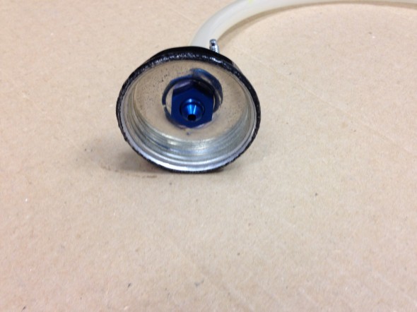
The Russell fitting was then pushed/screwed through the cap and the nut was tightened on the reverse side.

Russell Fitting Secured in Cap

Russell Fitting Secured in Cap

Russell Fitting Secured in Cap

Russell Fitting Secured in Cap

To help ensure the fitting would be air tight, I then smeared a fairly heavy coating of Clear RTV Silicone around the fitting and nut in the reservoir cap. Finally the rubber seal provided by Moss Motors was inserted into the inside of the cap.

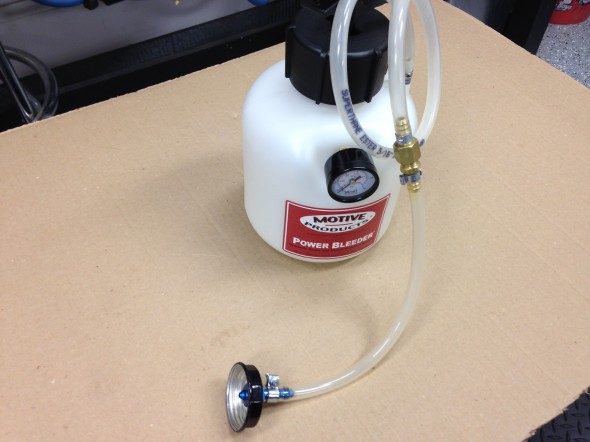
The new custom hose extension can then be attached to the pump hose and we are then ready to use the Motive Bleeder on a Big Healey.

Healey Custom Extension Connected to the Motive Power Bleeder

Healey Custom Extension Connected to the Motive Power Bleeder


June 12, 2014 – 

Conclave 2014 is to be held at the Homestead Resort, only two hours away from home. Judith and I will attend an plan to drive The Bloody Beast to the event. The car is generally in good condition, only needing a few things tended to before driving to Hot Springs, VA for the event.

  • Inspected and replaced the spark plugs, NGK BP6Es – stock number 7333.
  • Installed a new silicone rocker cover gasket, glued to the cover with permatex high temp red RTV silicone gasket maker. I then used Hylomar Advanced Formulation sealer (blue) between the gasket and the head. This work seemed to be effective in eliminating previous cover leaks. I have had problems with the gasket leaking with my cast alloy cover from Cape International. So, I will try this one from Gasket Innovations.http://www.gasketinnovations.com/index.php/gasket-innovations/product/110-gah-al6 
  • Polished the aluminum rocker cover and carb dashpots.
  • Repaired a bent exhaust hanger and leak.
  • Adjusted the adjustable steering wheel. The wheel had gradually moved toward the driver in an uncomfortable position. I was able to free the boss with channel locks and push the wheel to the dash fascia.
  • Removed each wire wheel and tire and polished all chrome and stainless steel. Approximately 1 1/2 hours per wheel.
  • Tightened the nuts on the rear tie down hooks. Both had become loose.
  • Checked all key fasteners to make sure they were secure: motor mounts, shocks, suspensions, propshaft and etc.
  • Washed the entire car, polished and waxed a few places.
  • Touched up paint in a few areas.
  • Cleaned all leather and vinyl surfaces and treated with Lexol.
  • Vacuumed carpets.
  • Polished chrome trim and cleaned windscreen and mirrors.

October 5, 2013 – 

I was doing a little engine bay wipe down after having the Bloody Beast on a little road rally in Northern Virginia when I noticed that the surface of the light relay box mounted on the left front inner wing had deteriorated in appearance. I should have put a clear coat on the zinc when the cover was new, but did not think about it at the time. Any way, I removed the cover, sanded and polished it the best I could and then clear coated it before re-installation. Back to looking good once again.

Light Relay Box Cover Clear Coated

Light Relay Box Cover Clear Coated

Clear Coated Relay Box In Place

Clear Coated Relay Box In Place

May 24, 2013 – 1,580 miles

  • Removed the itg air filter, cleaned it and sprayed it with dust retention spray.
  • Replaced the purolator fuel filter just in front of the carbs with a new one.
  • Replaced the thermostat with a 195 degree unit and added a new gasket.
  • Changed the oil (20W-50), 6.4 quarts.
  • Installed new K&N oil filter – HP.2009
  • Greased all grease fittings.
  • Cleaned the underside of the car including wheel wells.
  • Touched-up paint in a few places.
  • Checked tire pressures.

Hub Nuts

I had some problems with loosening hub nuts on the rear hubs and upon closer examination discovered that the proper Healey hub nuts do not fit the hub stud opening as they should. My conclusion is that the reproduced Healey hubs mimic the angle of more contemporary hub nuts. Dorman  #611-014 hub nuts fit much better than the original nuts.