Chapter 5 – Disassembly

June 29, 2002

Final Interior Dismantling

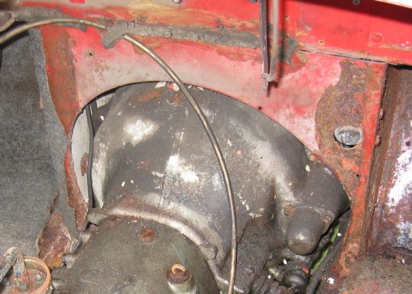
Gearbox tunnel and extension cover. Both were rusted badly and were discarded. I learned later as I was fitting new parts that I should not have violated the restorer’s rule: Never throw anything away until the project is complete!

Gearbox tunnel and extension cover

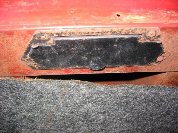
Fresh Air cover plate and screen on left (driver’s) side. Three self threading screws.

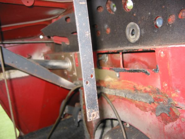
Parcel tray on passenger side. Four self tapping screws on the firewall. Three self tapping screws on the right side wall. One screw and nut into left side to hanging support bar. Then removed the parcel support bar with one screw and nut at top.

Parcel Tray Support brace.

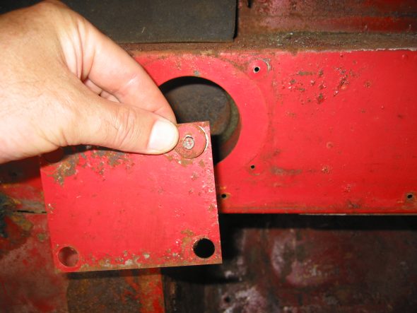
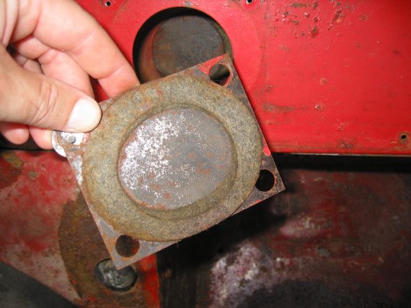
Steering Wheel Shaft Blanking Plate on the right side. Note larger “painted washers” and self tapping screws. Felt gasket found on reverse side of the plate.

Steering Wheel Blanking Plate

Steering Wheel Shaft Blanking Plate Felt Gasket

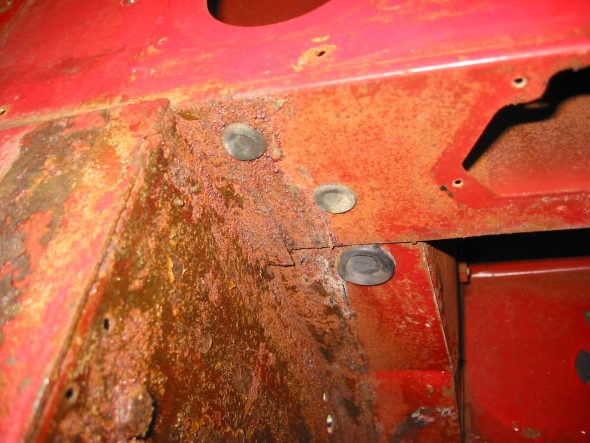
Two Blanking Screws into captive nuts in firewall on passenger side that just fill holes similar to the driver’s side. These were not painted.

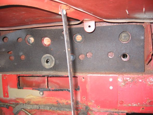
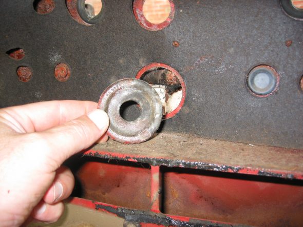
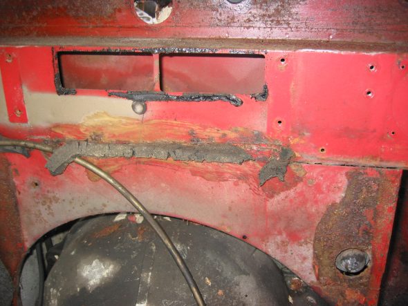
Large Wiring Harness Rubber Grommet in center of firewall. Then removed firewall tarpaper in center of firewall. Note the rubber insulation around the heater box hole and along the seam that would otherwise leak air.

Heat Insulation (tar paper) on firewall

Firewall Grommet

Heater Channel Opening

Center Panel Firewall “Tarpaper.” After removing the firewall “tarpaper” that is in three pieces I numbered the holes:

#1 – Bonnet release rod grommet

#2 – Blank Cover grommet

#3 – Grommet

#4 – Brake Line clip

#5 – Grommet

#6 – Grommet

#7 – Nut

#8 – Nut

#9 – Brake Line Clip

#10 – 1 Nut, 2 grommets Wiper motor

#11 – 2 Nuts

#12 – Nut

#13 – Nut

#14 – Nut

#15 – Nut

#16 – Main wiring harness to dash

#17 – Blank Cover Grommet

#18 – Nut

#19 – Nut

#20 – Nut

#21 – Grommet 

Left Panel Firewall “tarpaper”:

#22 – H2O temp. line

#23 – Oil line

#24 – Nut

Small Blanking Rubber Grommets under the heater opening in firewall. 

Blanking Rubber Grommets

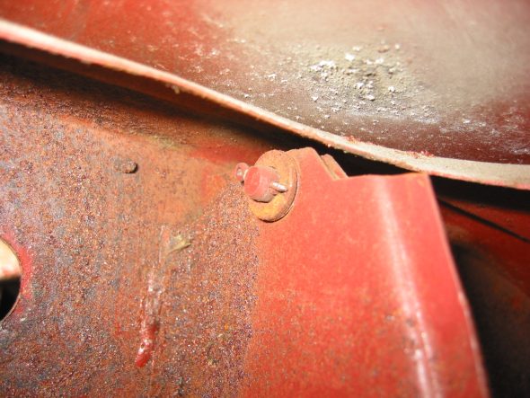
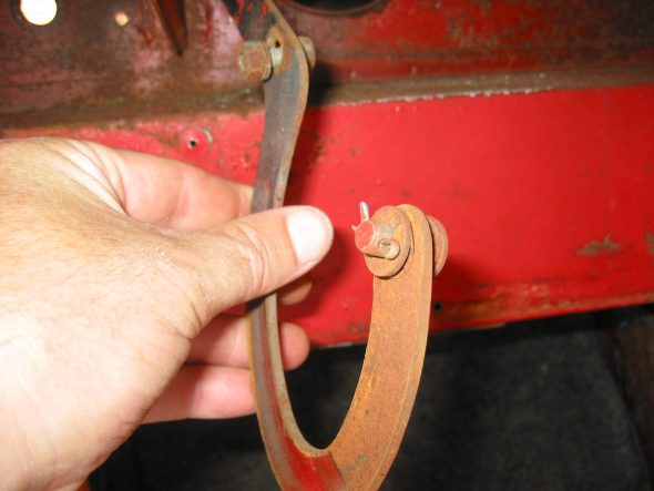
Right Bonnet Hinge cotter pin and 4 washers. The thin washers go closest to the hinge. The nuts go to the inside of the bonnet.

Bonnet Hinge Fixing

Bonnet Hinge

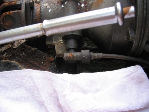
Speedometer Cable at “L” junction to the gearbox.

Speedometer Cable to Gearbox

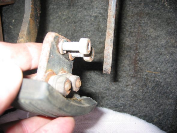
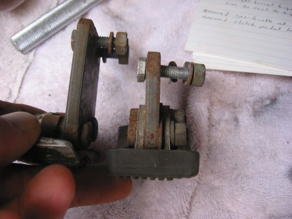
Clutch Pedal from pedal bar – two nuts. The nuts go to the right side. Removed the Brake pedal from pedal bar – two nuts with nuts to the right side. I noticed at this point that some primatively cut spacers had been added to the pedals for a short-legged driver!

Clutch Pedal

Clutch Pedal Spacer

Pedal Spacers

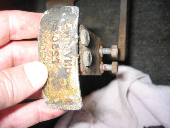
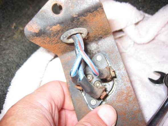
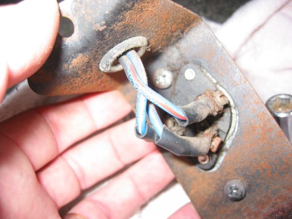
Floor Dip Switch with two bolts to the fixed nuts in floor. 3 wires: red/blue, blue/white, all blue.

Dip Switch Wiring and Bracket

Dip Switch

Heater Vents on both driver and passenger side below dash. Four self tapping screws in each

Heater Fresh Air Vent Door

July 2, 2002

Engine

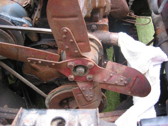
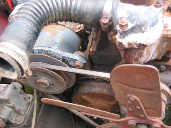
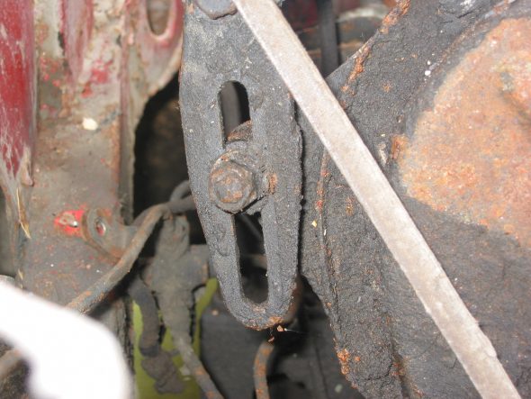
Fan and fan belt – Loosened 4 bolts and washers and removed the fan and fan belt.

Fan and Fan Belt

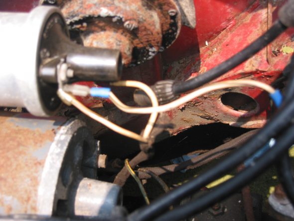
Wiring to the coil –  CB Terminal – White with black stripe from/to the distributor body and white with black stripe from harness that goes to the generator. SW Terminal – Large solid white wire from harness to generator.

Coil Wiring

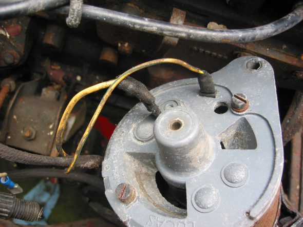
Generator – Removed 2 bolts and nuts and adjusting bracket with self-locking nut. F Terminal – yellow/green stripe wire from harness. D Terminal – Large solid yellow wire connected to large spade.

Dynamo – Generator

Generator Adjustable Mounting Bracket

Generator Wiring

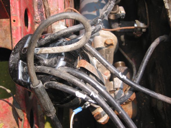
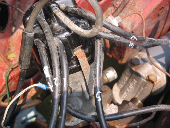
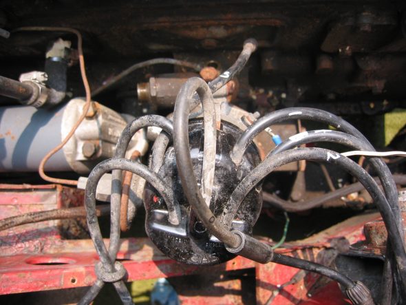
Distributor –  Removed two 7/16” bolts – note position of distributor and vacuum advance. Numbered each wire to the correct cylinder. Disconnect vacuum line and oil feed line to the tachometer drive.

Distributor Wiring

Distributor

Distributor Cap

Distributor Mounting Clamp

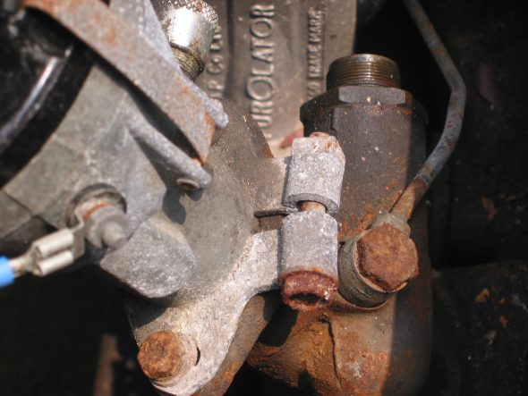
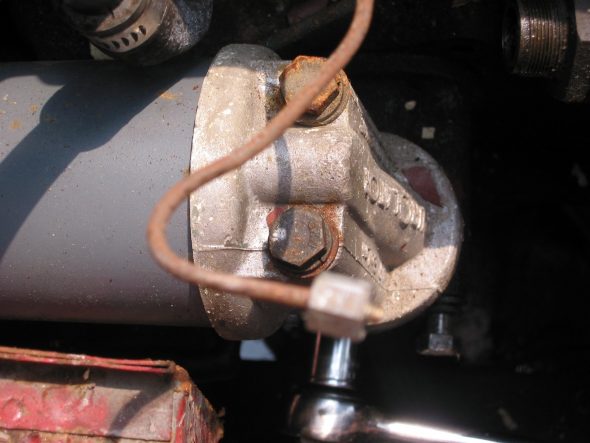
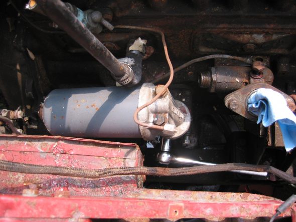
Oil Filter –  Removed two large bolts to the engine block.

Oil Filter Mount

Oil Filter

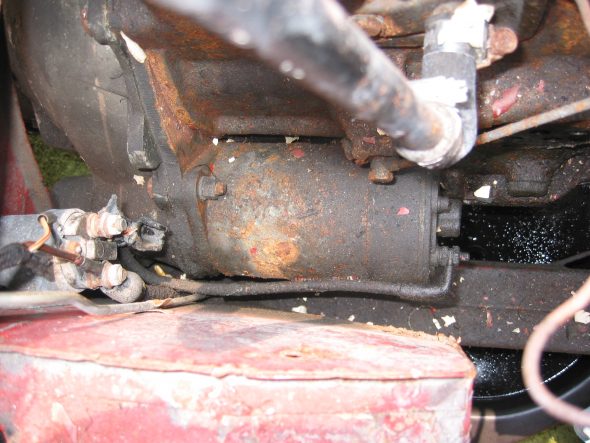
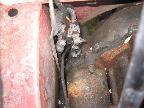
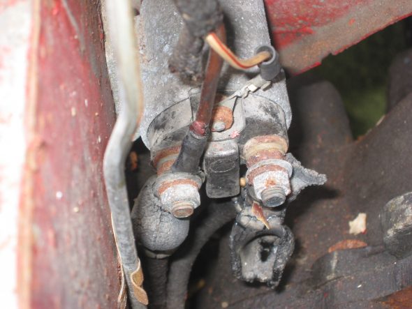
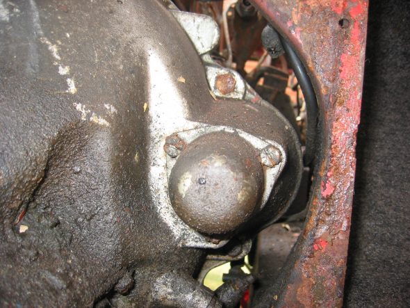
Starter and Solenoid  Disconnected solenoid to starter lead cable. Loosen two 9/16” bolts accessed through the interior bulkhead and under car.

Starter

Starter Solenoid

Starter Solenoid Wiring

Starter Cover

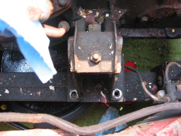
Engine mounts – Removed 4 bolts from right front to frame. Then removed left side.

Engine to frame Mount

Ground strap –  Disconnected the strap from the frame.

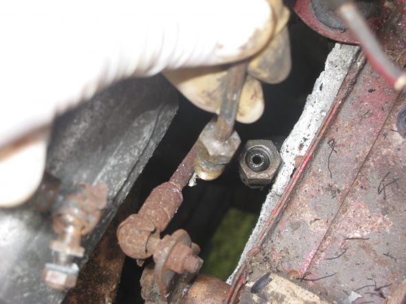
Oil pressure line –  Disconnected the line at top union near intake manifold.

Oil Pressure Line Disconnect

Breather pipe –  Disconnected the pipe at the “T” junction on the rocker cover.

Breather Pipe Disconnect


Bloody Beast Maintenance

Maintenance

October, 2014 – 

Returning home from the Shenandoah Valley British Car Club show in Waynesboro, VA I noticed that the clutch pedal was slippery. Sure enough the seals in the master cylinder failed and I had some nasty brake fluid leaking from the cylinder. I removed both the brake and clutch masters figuring that I might as well rebuild them both at the same time. Both were brand new when installed in the car, so other than cleaning the bores I did not bother with a full rebuild including honing or lining the bores. I have fewer than 12,000 miles on the originals, but it has been five or six years and who know how long they were on the shelf before I installed them?

Both of my masters were 5/8″ bores and I decided to purchase a new 3/4″ bore for the brake system. Ordered one from British Parts Northwest.

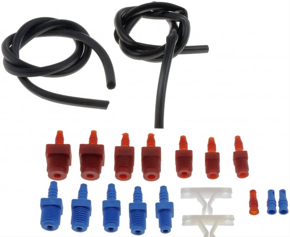
In preparing to bench bleed the two masters I decided to purchase a little “HELP” kit from Summit Racing for all of $6.00. I did substitute clear hose for the black vinyl so that I could observe the air bubbles flowing to the fluid reservoir. The Healey master cylinders use the 3/8″ –  24 and the 7/16″ – 20 fittings, but many others are supplied in the kit.

Dorman Bench Bleeder Kit

Dorman Bench Bleeder Kit

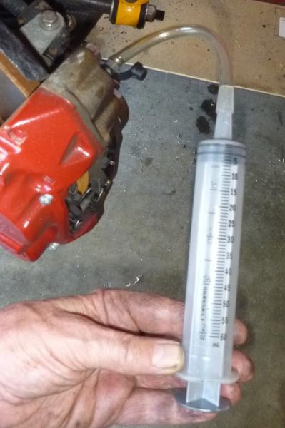
Steve Gerow on the British Car Forum recommended “pulling” the air from the brake calipers rather than pushing the fluid from the reservoir:

“This bleeding syringe worked a charm, obviating the need for bench-bleeding. My Healey-neighbor Dennis Williams suggested packing the area around the nipple with grease to prevent air leakage. You just pull the air out of the system until you’ve got clear, bubble-free juice in the syringe. Keep an eye on the reservoir, of course.”

Cardone Brake Bleeding Syringe

Cardone Brake Bleeding Syringe


Steve often comes up with the innovative ways of approaching maintenance issues so I thought I would give it a try. These are the directions that came with the syringe:

Cardone 10-5000MCB Master Cylinder Bleeder Tool Directions

I was overdue for a complete brake fluid flush so I pumped out all of the old stuff while I was at it.

Motive Power Bleeder

I have had a Motive Power Bleeder http://www.motiveproducts.com for several years and never used it. I ordered the special reservoir cap specified for the Healey – Part number 1100 I believe. It did not fit!

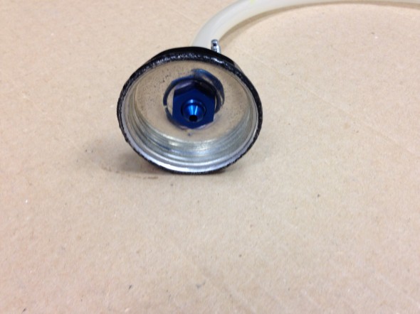
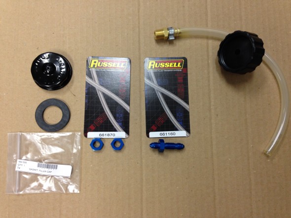
This master cylinder episode got my inspired to solve this little problem. I ordered another master cylinder reservoir cap and seal from Moss Motors. Part numbers 596-210 and 582-500. I then went on a search for a 1/4 brass fitting to install in the cap. The fitting was easy to find but after trying two automotive parts stores, a “they have it all” hardware store and a large plumbing supplier I gave up on finding a nut with the proper pipe thread! Finally, at a local fabrication shop I found these Russell fittings and they worked perfectly. The hose and cap #1100 to the right in the image below were supplied with the Motive Bleeder. I just disconnected the hose from the cap that did not fit.

Reservoir Cap Modification for Motive Bleeder

Reservoir Cap Modification for Motive Bleeder

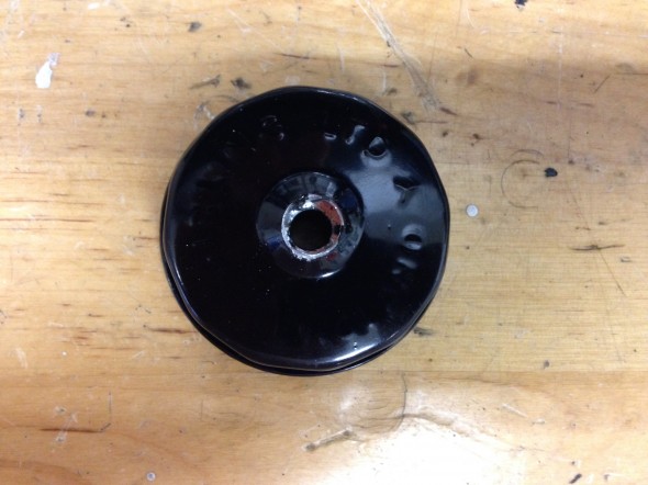
I then drilled a hole in the center of the Healey reservoir cap to tightly fit the Russell hardware. This required flattening the center of the cap which is raised on its top and bottom. Flattening the top is easier to do AFTER the hole is drilled in the top.

Drilled Hole in Cap

Drilled Hole in Cap 

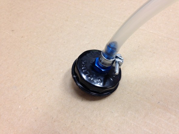
The Russell fitting was then pushed/screwed through the cap and the nut was tightened on the reverse side.

Russell Fitting Secured in Cap

Russell Fitting Secured in Cap

Russell Fitting Secured in Cap

Russell Fitting Secured in Cap

To help ensure the fitting would be air tight, I then smeared a fairly heavy coating of Clear RTV Silicone around the fitting and nut in the reservoir cap. Finally the rubber seal provided by Moss Motors was inserted into the inside of the cap.

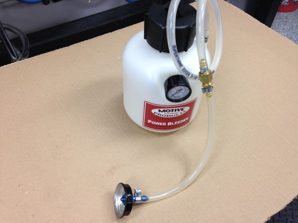
The new custom hose extension can then be attached to the pump hose and we are then ready to use the Motive Bleeder on a Big Healey.

Healey Custom Extension Connected to the Motive Power Bleeder

Healey Custom Extension Connected to the Motive Power Bleeder


June 12, 2014 – 

Conclave 2014 is to be held at the Homestead Resort, only two hours away from home. Judith and I will attend an plan to drive The Bloody Beast to the event. The car is generally in good condition, only needing a few things tended to before driving to Hot Springs, VA for the event.

  • Inspected and replaced the spark plugs, NGK BP6Es – stock number 7333.
  • Installed a new silicone rocker cover gasket, glued to the cover with permatex high temp red RTV silicone gasket maker. I then used Hylomar Advanced Formulation sealer (blue) between the gasket and the head. This work seemed to be effective in eliminating previous cover leaks. I have had problems with the gasket leaking with my cast alloy cover from Cape International. So, I will try this one from Gasket Innovations.http://www.gasketinnovations.com/index.php/gasket-innovations/product/110-gah-al6 
  • Polished the aluminum rocker cover and carb dashpots.
  • Repaired a bent exhaust hanger and leak.
  • Adjusted the adjustable steering wheel. The wheel had gradually moved toward the driver in an uncomfortable position. I was able to free the boss with channel locks and push the wheel to the dash fascia.
  • Removed each wire wheel and tire and polished all chrome and stainless steel. Approximately 1 1/2 hours per wheel.
  • Tightened the nuts on the rear tie down hooks. Both had become loose.
  • Checked all key fasteners to make sure they were secure: motor mounts, shocks, suspensions, propshaft and etc.
  • Washed the entire car, polished and waxed a few places.
  • Touched up paint in a few areas.
  • Cleaned all leather and vinyl surfaces and treated with Lexol.
  • Vacuumed carpets.
  • Polished chrome trim and cleaned windscreen and mirrors.

October 5, 2013 – 

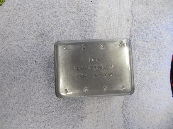
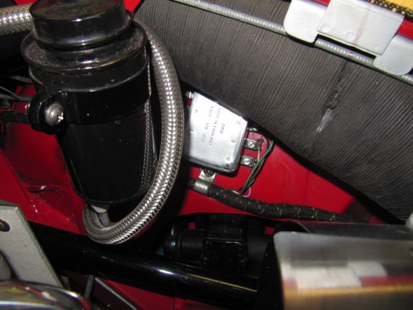
I was doing a little engine bay wipe down after having the Bloody Beast on a little road rally in Northern Virginia when I noticed that the surface of the light relay box mounted on the left front inner wing had deteriorated in appearance. I should have put a clear coat on the zinc when the cover was new, but did not think about it at the time. Any way, I removed the cover, sanded and polished it the best I could and then clear coated it before re-installation. Back to looking good once again.

Light Relay Box Cover Clear Coated

Light Relay Box Cover Clear Coated

Clear Coated Relay Box In Place

Clear Coated Relay Box In Place

May 24, 2013 – 1,580 miles

  • Removed the itg air filter, cleaned it and sprayed it with dust retention spray.
  • Replaced the purolator fuel filter just in front of the carbs with a new one.
  • Replaced the thermostat with a 195 degree unit and added a new gasket.
  • Changed the oil (20W-50), 6.4 quarts.
  • Installed new K&N oil filter – HP.2009
  • Greased all grease fittings.
  • Cleaned the underside of the car including wheel wells.
  • Touched-up paint in a few places.
  • Checked tire pressures.

Hub Nuts

I had some problems with loosening hub nuts on the rear hubs and upon closer examination discovered that the proper Healey hub nuts do not fit the hub stud opening as they should. My conclusion is that the reproduced Healey hubs mimic the angle of more contemporary hub nuts. Dorman  #611-014 hub nuts fit much better than the original nuts.

Engine Rebuild

Clean-up Before Rebuild

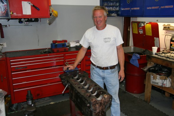
I had thought about outsourcing the machine block cleaning and machine work and then rebuilding the engine myself, but thought better of it given time limitations and decided to go ahead and give the complete engine to Mike Gassman at Gassman Automotive http://www.gassmanautomotive.com for a soup to nuts rebuild. Mike and his team had done XK motors before and are experienced with the motor, ignition, fuel system and etc.

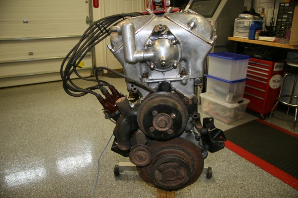
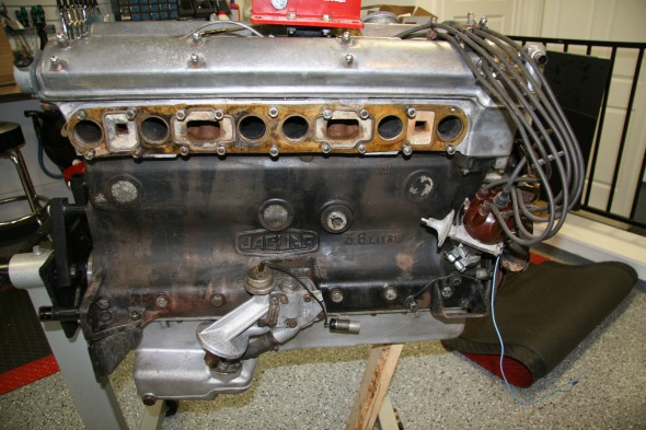
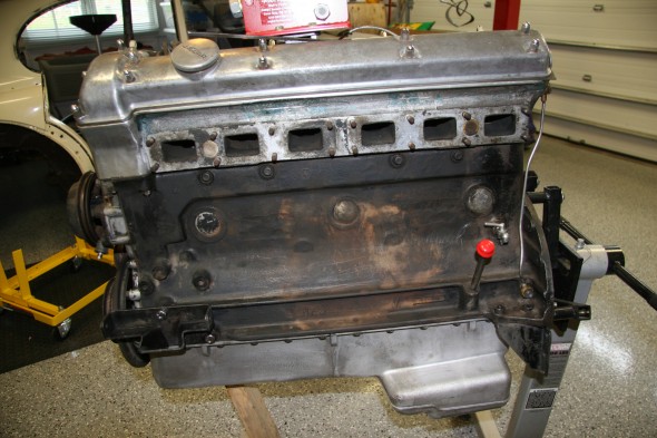
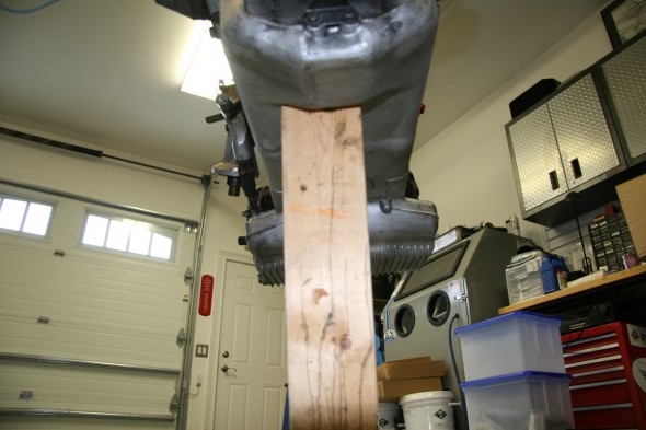
I spent a few days cleaning the block and head to remove as much grease and grime as possible before turning everything over to Mike.

Front of Cleaned Engine Before Rebuild

Front of Cleaned Engine Before Rebuild

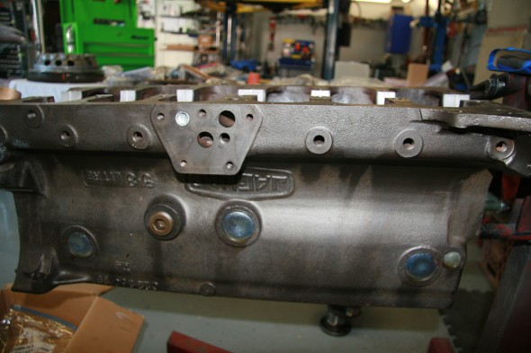
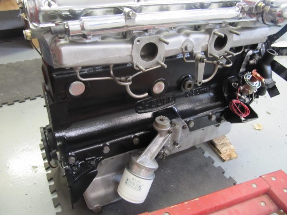
RH Side of Engine

LH Side Engine

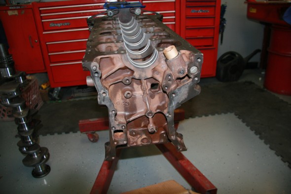
Underside of Engine

Rebuild Engine

Machine Work:

  • Resurface Head
  • Valve Job
  • Install Guides
  • Pressure Test
  • Resurface and weld Exhaust Manifold Cracks
  • Drill for Oversize Lifters
  • Drill for Hold Downs
  • R&R Pistons
  • R&R Bushing Under Over
  • Recondition Big End
  • Grind and Polish Crankshaft
  • Magna-Flux Crankshaft
  • R&R Crank Plugs
  • Rebore and Hone Block
  • Pins
  • Replace Core Plugs
  • Balance Pressure Plate, Cylinder Block
  • Resurface Flywheel
  • Magna-Flux Block
  • Resurface Cylinder Head
  • Polishing Two Valve Covers, Two Carbs Dashpots, Intake Manifold, Oil Cap, Cover and Water Neck

Parts:

Where possible used components in good shape were used in the rebuild; however, in many instances new parts were required to replace worn or broken bits. The original compression for the 3.8 MK2 engine was 9:1; however, primarily because of the lower octane rating of fuel today and due to the way I plan to use this car, I decided to use 8:1 compression Mahle pistons in my rebuild. This is not a complete list and it is in no particular order, but new parts ordered included the following:

  • Cam bearing Set
  • Engine chrome hardware
  • Oil Filter
  • Spin-On Oil Filter Kit
  • Payen Brand Head Set
  • Cylinder Head Studs
  • Seal Kit
  • Lock Tab Kit
  • Thrust Washer Set
  • Piston set
  • Tri-metal Connecting Rod Bearing Set
  • Tri-metal Main Bearing set
  • Core Plug Set
  • Pilot Bushing
  • Clutch Kit
  • Water Pump
  • Timing Chain, Guide and Tensioner kit
  • Lower Gasket Set
  • Tappet Hold Down Kit
  • Tappet Guide
  • Valve Spring Set
  • Oil Pump
  • Oil Pump Adapter
  • Bronze Valve Guide Set
  • Intake Valves
  • Exhaust Valves
  • Oversize Tappets
  • 10W30 Break in Oil with Zinc Additive
  • 15W50 Oil with Zinc
  • Engine and Bearing Assembly Lubricant
  • Sealants/Sealers/Cam Lube
  • Gloss Black paint
  • Metallic Blue Spray Paint for the Cylinder Head
  • Flamethrower Coil
  • Chrome Coil Bracket
  • Flamethrower Ignition Leads
  • Spark Plugs
  • 123 Distributor
  • Brass Nuts
  • Thermostat
  • S.U. Throttle Shaft 1 3/4″ Butterflies
  • S.U. 1 3/4″ Butterflies
  • 5/16 22 BSF Banjo Bolt HD Starting Carb
  • 3.8 MK2 SM/1402 Carb Kits
  • Drive Belt
  • Hoses to Radiator
  • Radiator Hose Clamps
  • Heater Hose
  • Heater Hose Clamps
  • Gear Reduction Starter
  • Engine Ground Strap
  • Oil Pressure Sender
  • Oil Quick Drain Valve
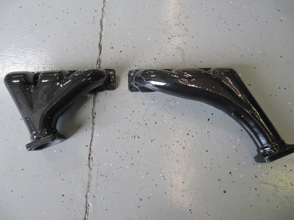
  • Blast, Anneal and Porcelain Coat Exhaust Manifolds
  • Carb Banjo Bolts and Washers
  • Alternator and Mounting Bracket

Rear Main Crankshaft Seal

I did some research on the replacement of the rear main crankshaft seal. A number of the usual vendors sell modern upgrades for this seal to help prevent oil leakage. The apparent most popular upgrade kit does require some machining of the crank.

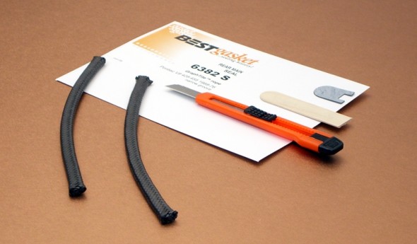
After checking with those on the saloon-lovers forum and a few other MK2 owners, the consensus seemed to be to stay away from the upgrade kits. However, Peter Wise aka “Old Goat” [email protected] recommended a GraphTite seal made by BEST Gaskets as a modern material upgrade to the original rope seal. The kit is available from EGGE Machine http://www.egge.com  part number: 6382S and it is for a Pontiac 1968-76 8 cylinder 428-455. It is a direct replacement for the rope and does not require any machine work. I cannot explain why the Pontiac V-8 seal works in the MK2 3.8 but Pete claims that it works quite well. I have ordered the kit and Mike and his team installed the seal upon rebuild. The seal kit included an installation tool for $17.39!

GraphTite Rear Main Seal

GraphTite Rear Main Seal

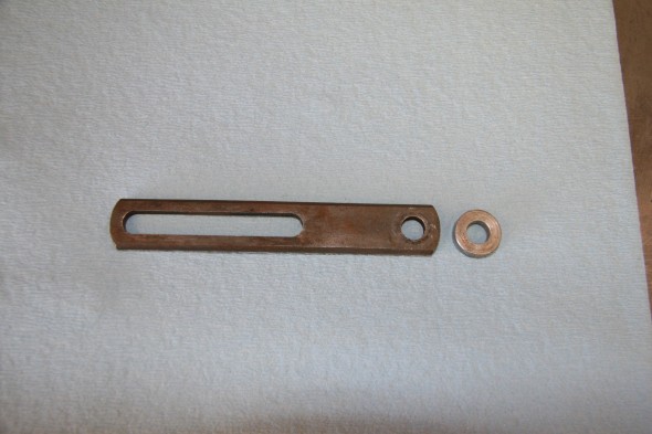
Dynamo Mounting Bracket and Spacer

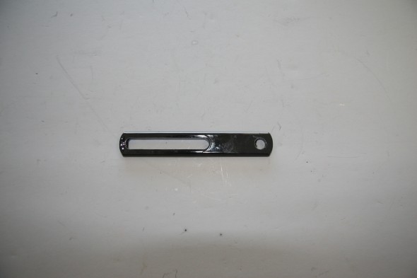
I probably will not use the dynamo bracket with my alternator, in favor of a turnbuckle brace, but I cleaned it up and painted it  – just in case.

Dynamo Adjustment Bracket


Dynamo Bracket

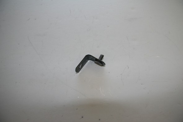
Coil Bracket Extension

Coil Mounting Bracket Extension

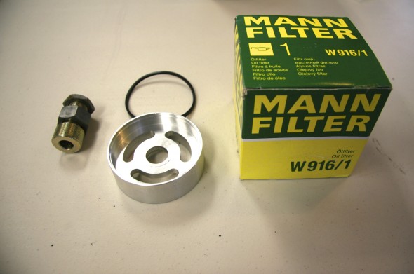
Spin-on Oil Filter Kit

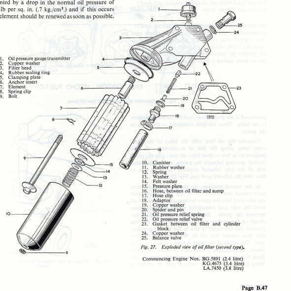
Oil Filter Assembly

Oil Filter Assembly

As seen in the image above, the original oil filter is a full flow type and has a renewable felt or paper element. Modern spin-on alternatives are available and I installed the kit provided by SNG Barratt. Purists may object, but most who have installed the spin-on arrangement report success and it is certainly much easier to change.

Spin-on Oil Filter Instructions

SNG Barratt Spin On Oil Filter Kit

SNG Barratt Spin On Oil Filter Kit

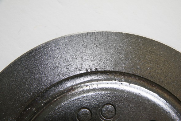
Harmonic Balancer

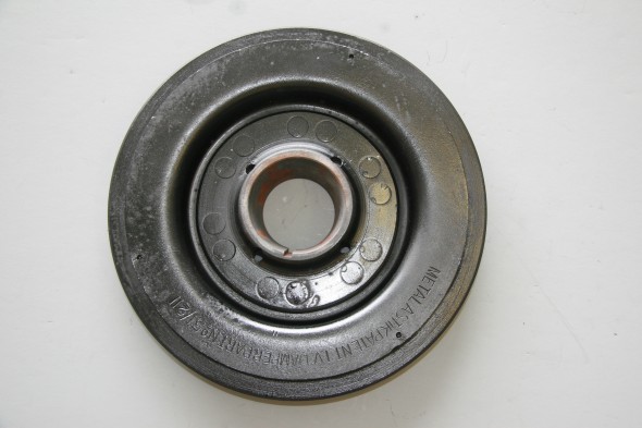
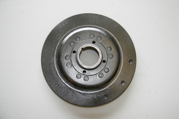
I decided to have the harmonic balancer rebuilt by Dale Manufacturing http://hbrepair.com/harmonicbalancer_018.htm in Salem, Oregon rather than purchase a new one. The rebuild was under $150 and the final product looked pretty good.

Harmonic Balancer

Harmonic Balancer

Timing Marks

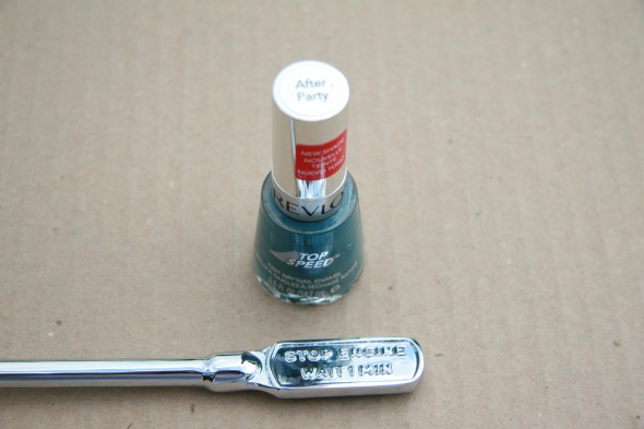
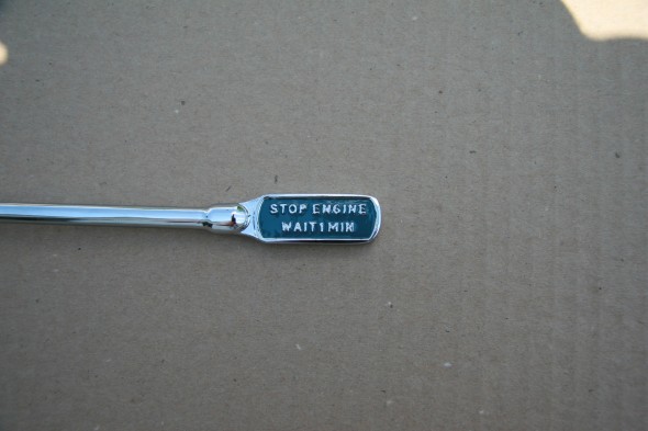
Oil Sump Dipstick

Got the dipstick back from the plater. I vaguely recalled that the background on the handle was a somewhat unusual blue color. Someone on the Forum indicated that Revlon’s After Party nail polish was the perfect color, so I ordered some and painted the handle:

Revlon's After Party Nail Polish

Revlon’s After Party Nail Polish


Revlon's After Party Nail Polish after Application

Revlon’s After Party Nail Polish after Application

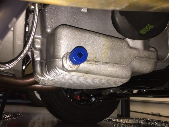
Oil Drain Plug

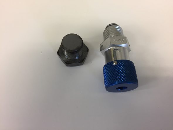
I ordered an EZ Oil Drain Valve for XK Engines from Cool Cat Express just to make the oil drain process a little easier. As their advertisement says; “This all aluminum drain valve mounts permanently in place of your drain plug. A simple twist of the wrist will open and close it. No more stripped threads, no more lost plugs. One piece aircraft quality 6061 aluminum and 302 stainless steel. Aluminum has clear anodized finish for long, corrosion free life. Seals are replaceable. Nothing to break, nothing to lose: saves labor, saves your oil pan, save aggravation. The perfect companion for our spin on conversion kits! Fits all Jaguar oil pans with 5/8″-18 thread. This includes ALL XK motors, and many V12’s.”

This is a photo of the Valve and the plug it replaces:

Cool Cat Express Oil Drain Plug

Here is a photo of the new valve installed:

Cool Cat Express Oil Drain Valve Installed

Engine Rebuild Process

Mike Gassman Installing bearings

Mike Gassman Installing Bearings

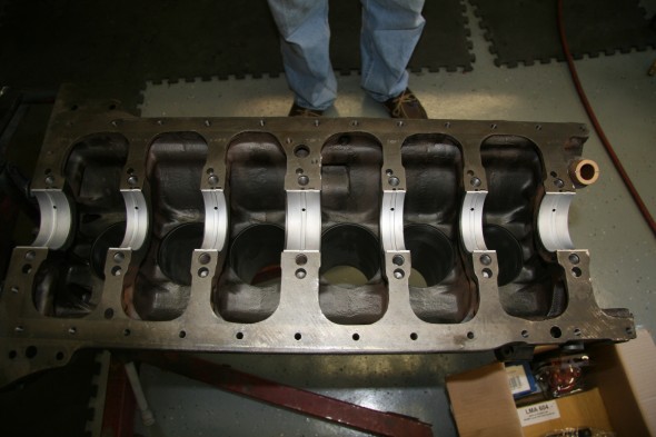
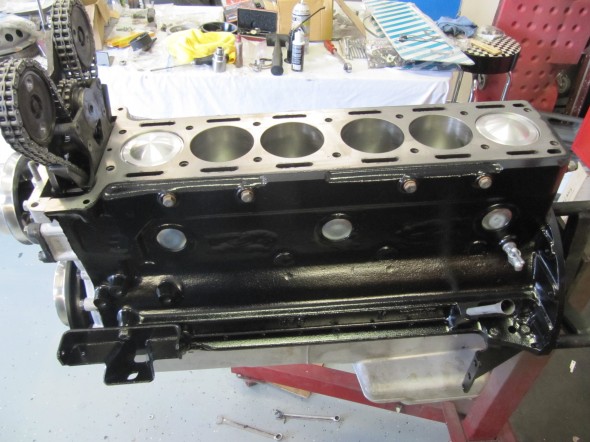
Engine Block

Engine Block

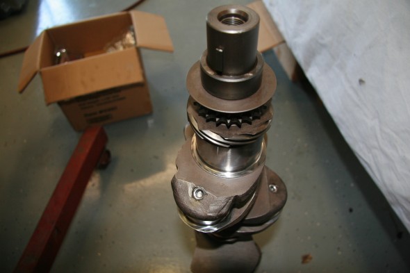
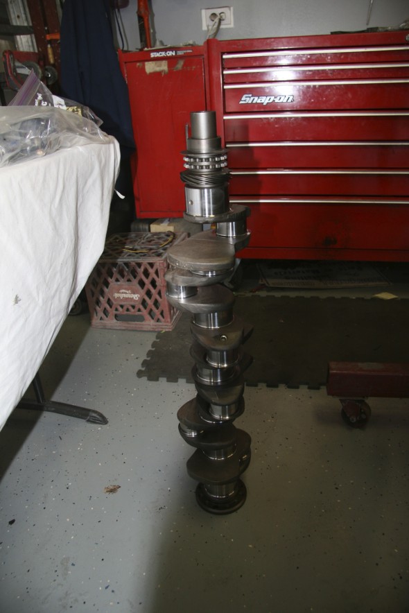
Crankshaft

Crankshaft

New Main Bearings

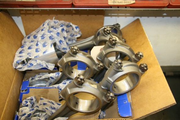
Connecting Rods

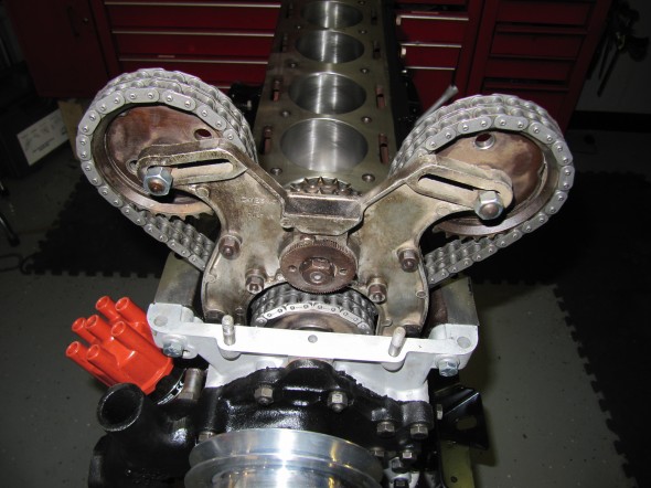
Timing Gear Chain

Pistons & Timing Gear

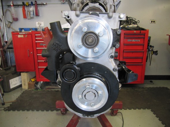
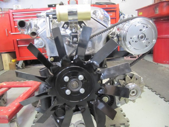
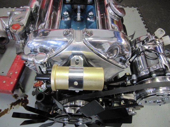
RetroAir Aluminum Pulleys


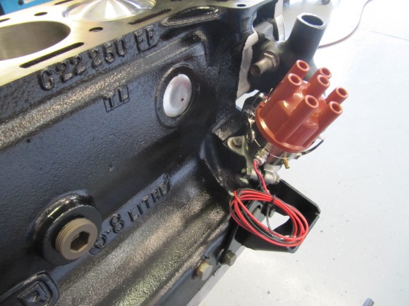
123 Distributor

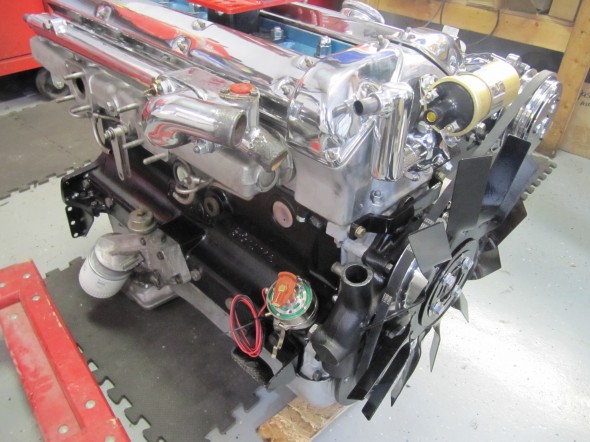
New Porcelain Exhaust

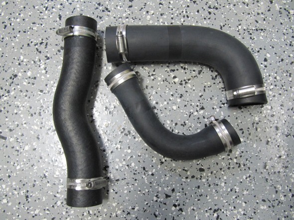
Primary Coolant Hoses

Engineering Art

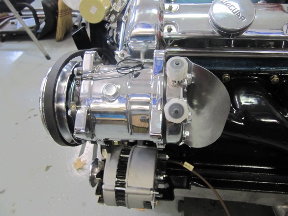
Compressor & Shield

New Belt Routing

Distributor

Spin-on Filter

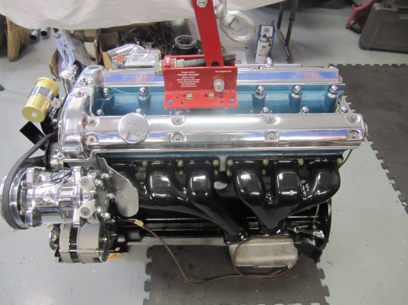
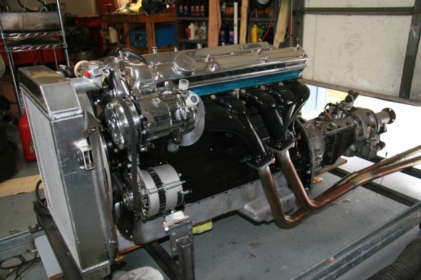
Front View

Engine Run-In

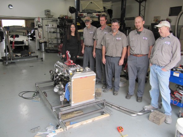
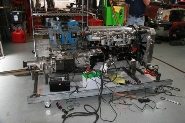
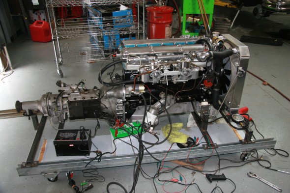
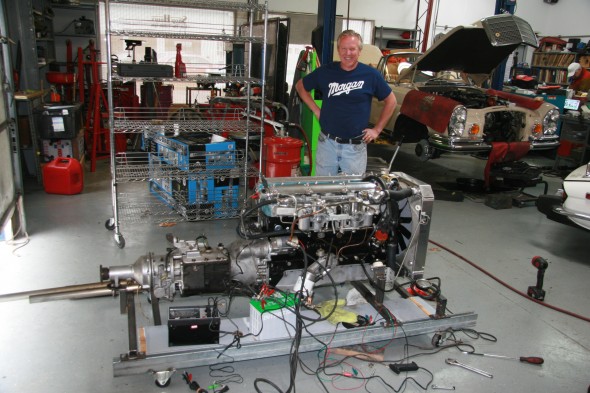
After Mike and his staff got the engine together they made a test stand so that we could do preliminary adjustments and make sure we were leak free. I am trying Evans Waterless Coolant in this engine and it was used in the testing.

All of the attention to balancing really paid off as the engine runs very smoothly with very little vibration. Everything checked out beautifully.

Thanks to Mike for a beautiful engine and a beautiful job. I recommend him to others without reservation.

The Gassman Team

The Gassman Team

Engine Testing

Engine Testing

Engine Testing

Maestro Mike

Maestro Mike


Engine Clean-up and Reinstall

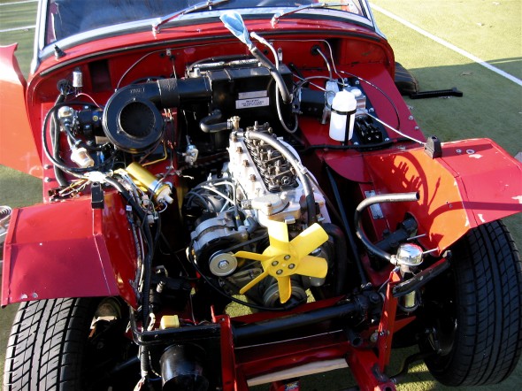
Engine Install

Engine Install

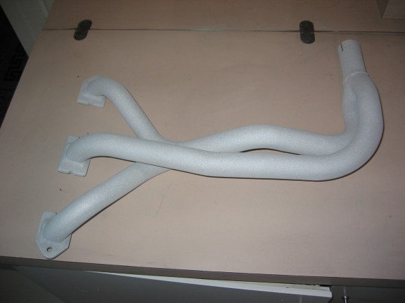
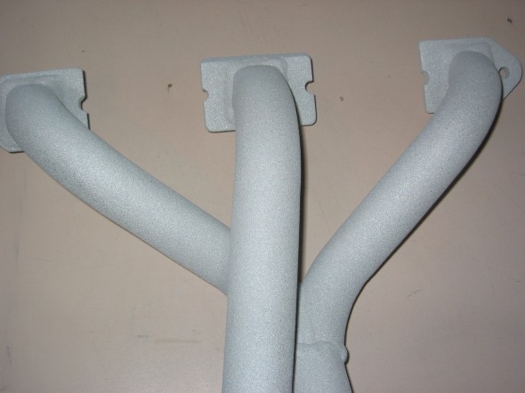
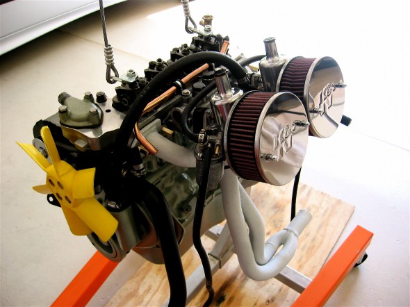
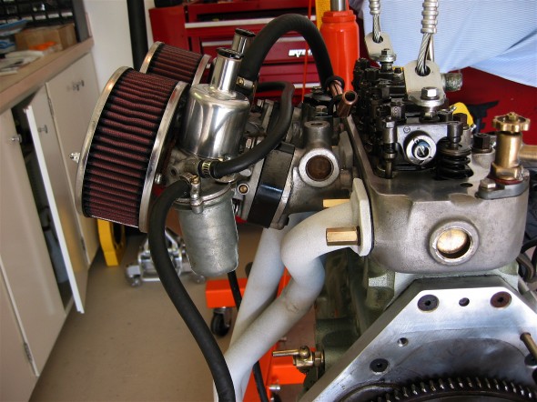
One of the things I wanted to accomplish with the engine clean-up was to have the  exhaust header coated to reduce heat in the engine compartment and interior. I used Swain Coatings. The header came back looking great. Time will tell if the coating holds up and is effective in reducing heat.

Swain Coat Header

Swain Coat Header

Swain Coat Header

Swain Coat Header

I also did a general cleaning of the engine including a new paint job while the gearbox was being worked on by Jack Harper. I replaced the oil sump gasket and the rocker cover gasket, too. I tested and reinstalled the gear reduction starter. The air cleaners were cleaned and oiled with K&N products.

Clean Motor Assembly

Clean Motor Assembly

Clean Motor Assembly

Clean Motor Assembly

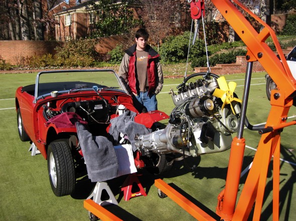
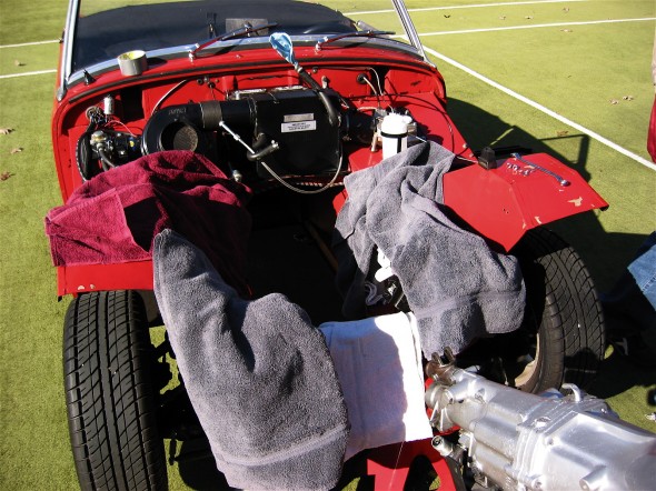
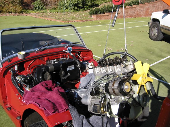
I developed the following list of items for reinstalling the engine and gearbox into the Bugeye:

Reinstalling a Bugeye Engine and Datsun 5-speed Transmission

  1. Grease the shaft splines on the engine and the yoke before installing the engine.
  2. Set the exhaust header in place so that it will be positioned to install once the engine is tightened into its mounts.
  3. Guide the motor into place with the lift so that the yoke on the driveshaft lines up with the transmission. If this does not work then remove the driveshaft and install after the engine and transmission are in place.
  4. Loosely secure the engine to the front motor mounts. The mounts themselves should be loose then tightened after all bolts/nuts are in place.
  5. Install the long bolts up through the crossmember into the rear transmission mount and tighten.
  6. Tighten the front engine mounts.
  7. Center the transmission in the rear mount, then push it as far to the right as possible, and tighten the transmission pad mounts on the bracket.
  8. Install the bolts in the sides of the transmission rear mounts from inside the car with the self locking nuts inside the tunnel. (Hint: tape the nuts in the wrench to make starting the threads easier.)
  9. Replace the gearshift lever.
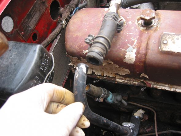
  10. Connect the ground strap to the frame of the car.
  11. Replace the rocker cover and connect the breather hose.
  12. Install the intake and exhaust manifolds.
  13. Install heat shield and carbs.
  14. Connect throttle and choke cables.
  15. Connect breather hose.
  16. Connect hot water hose to copper tube and connect to radiator hose. Tighten clamps. It is easier to put the clamp on the hose/copper pipe when the copper pipe clips are loose from the manifold.
  17. Connect the short hot water hose from the water control valve to the heater.
  18. Connect the electrical cable from the gear reduction starter to the starter solenoid.
  19. Connect the oil pressure pipe to the fitting on the engine block by the banjo bolt.
  20. Reconnect the white/black line from the electronic ignition to the distributor.
  21. Connect the high tension line from the distributor to the coil.
  22. Reconnect the plastic terminal (3 wires) to the alternator.
  23. Connect the fuel line from the fuel pump to the carbs.
  24. Reattach the water temperature sensor to the engine head.
  25. Remove the banjo bolt where the oil line exits the rear of the block. Pour motor oil down the hole in the block to prime the oil pump. Reinstall the bolt.
  26. Remove the oil filter and pour it full of motor oil and reinstall.
  27. Fill engine with oil – Castrol GTX 10W-40.
  28. Fill the gearbox with Gear lube – Redline MT90. 2 1/4 pints. Use long clear plastic tube. Try pump.
  29. Connect the stainless steel flex line from the master cylinder to the slave cylinder.
  30. Bleed the clutch slave cylinder. (See Page 9 of Rivergate’s manual)
  31. Install radiator and fill with 50% coolant and 50% distilled water.
  32. Fix the carb drain lines to the mounting clamp at the lower rear of the engine compartment.
  33. Insert the 1 ½” connecter pipe (with sealant) for the exhaust system into the header pipe.
  34. Install the exhaust and muffler assembly.
  35. Tighten clamps on the exhaust connecter pipe.
  36. Reconnect the battery cables.
  37. When ready to start the engine, pull the spark plugs and spin the engine with the starter until the oil pressure goes up to normal on the pressure gauge, and stays.
  38. Check for any oil, coolant and fuel leaks.
  39. Reinstall the spark plugs and start engine.
  40. If engine does not start turn distributor 180 and try again!
  41. Install 4” fresh air heater hose and clamp.
  42. Install the leather shifter cover and surround.

Start It Up And Have Some Fun!

I Know It Fits!

I Know It Fits!

Motor Protection!

Motor Protection!


Engine Install

Engine Install