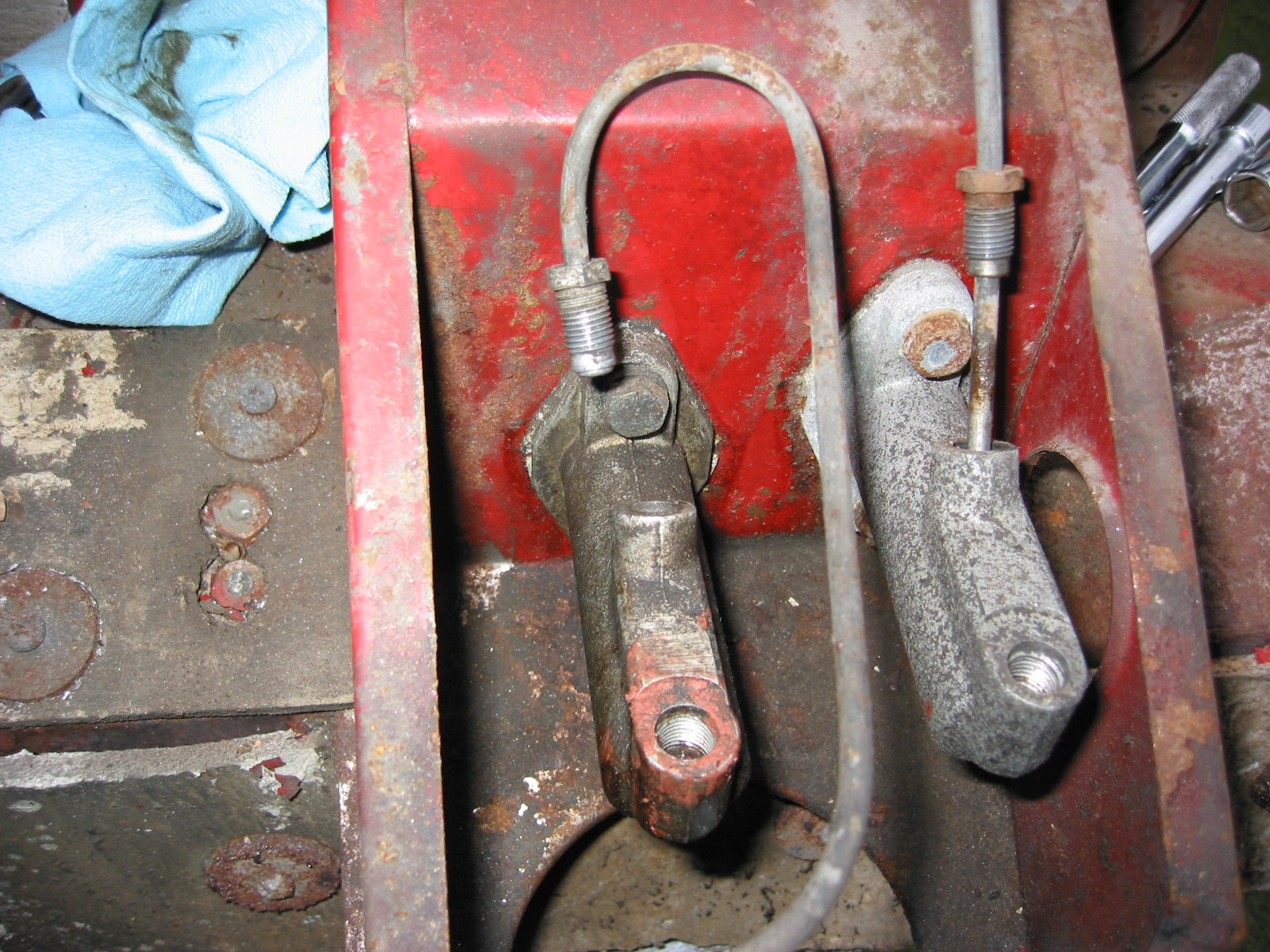
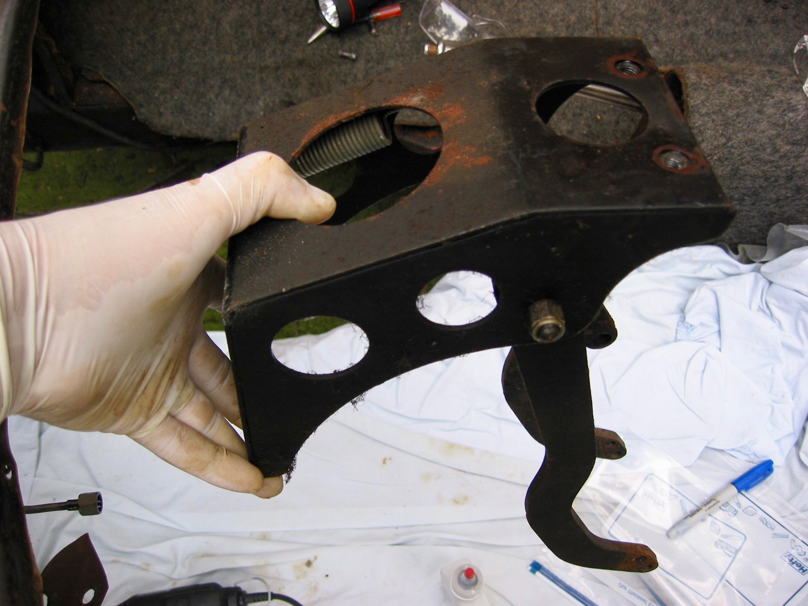
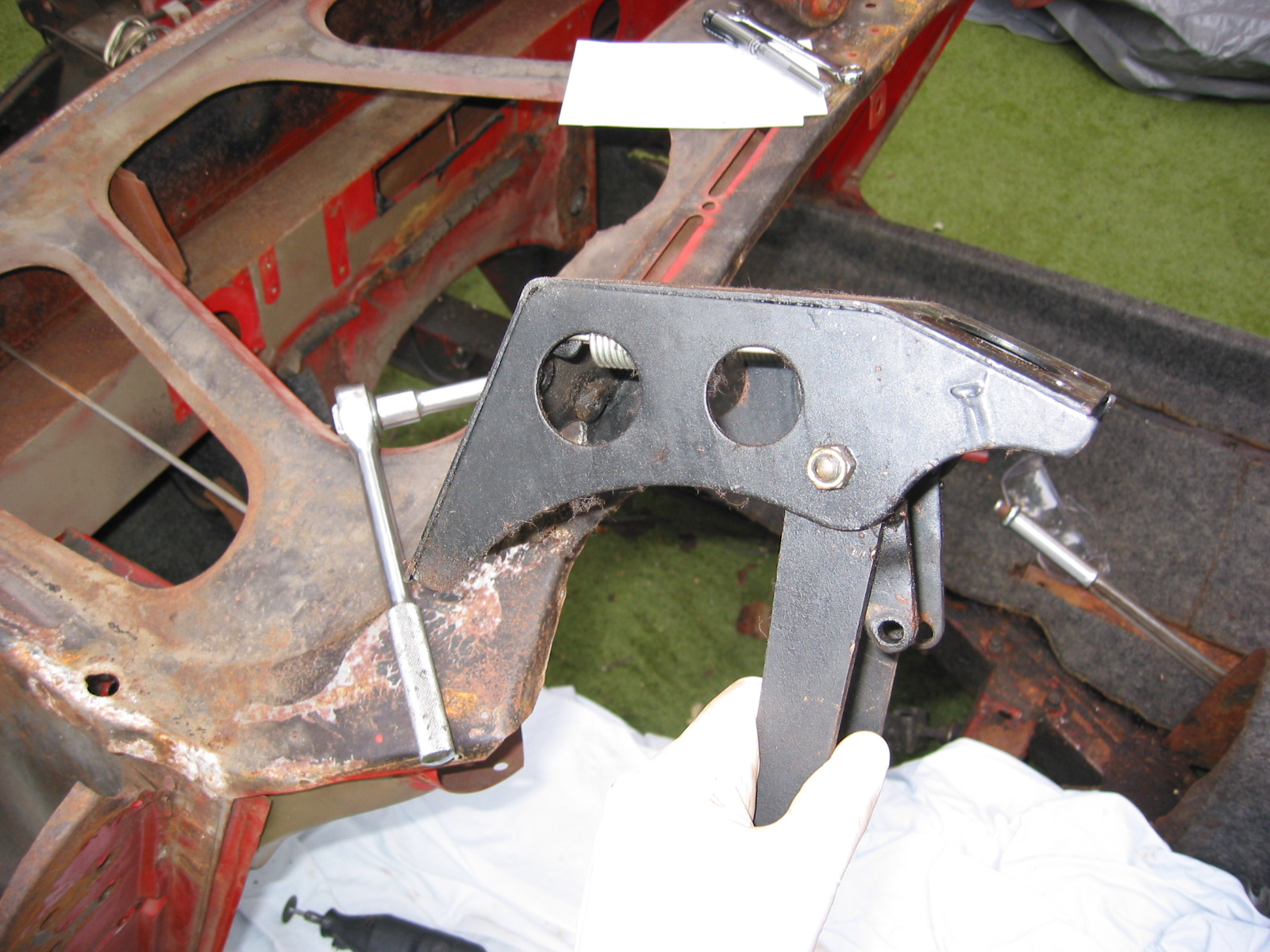
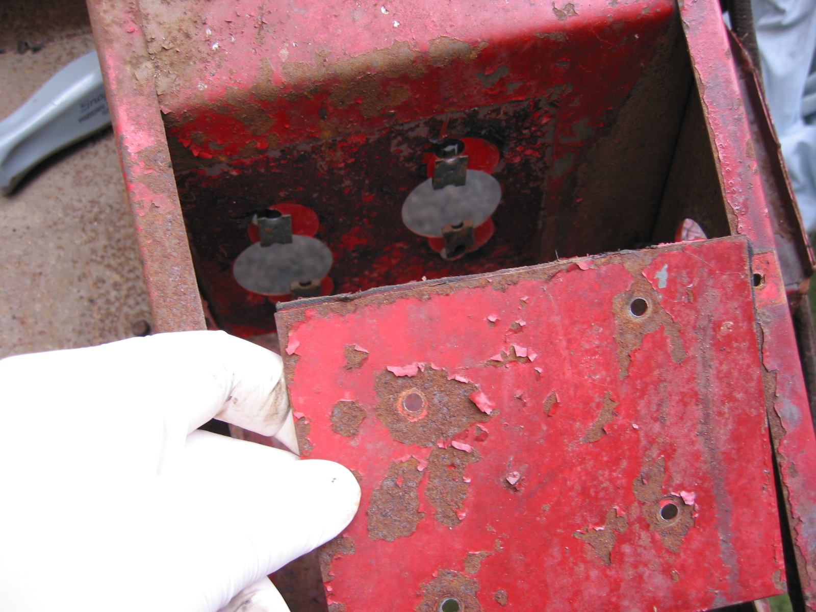
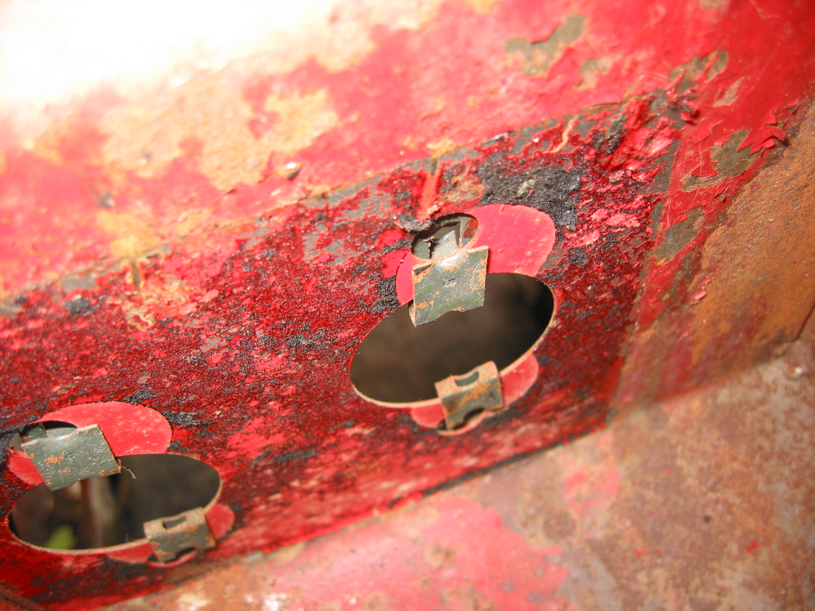
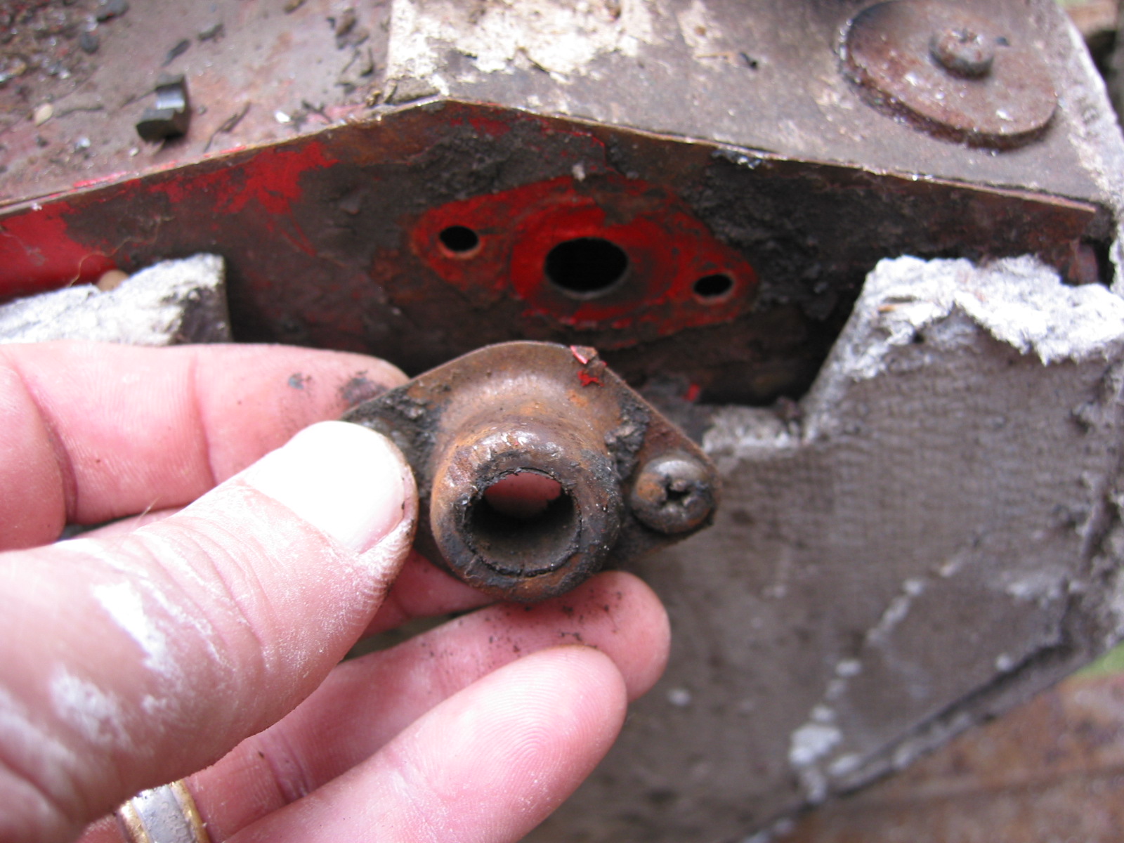
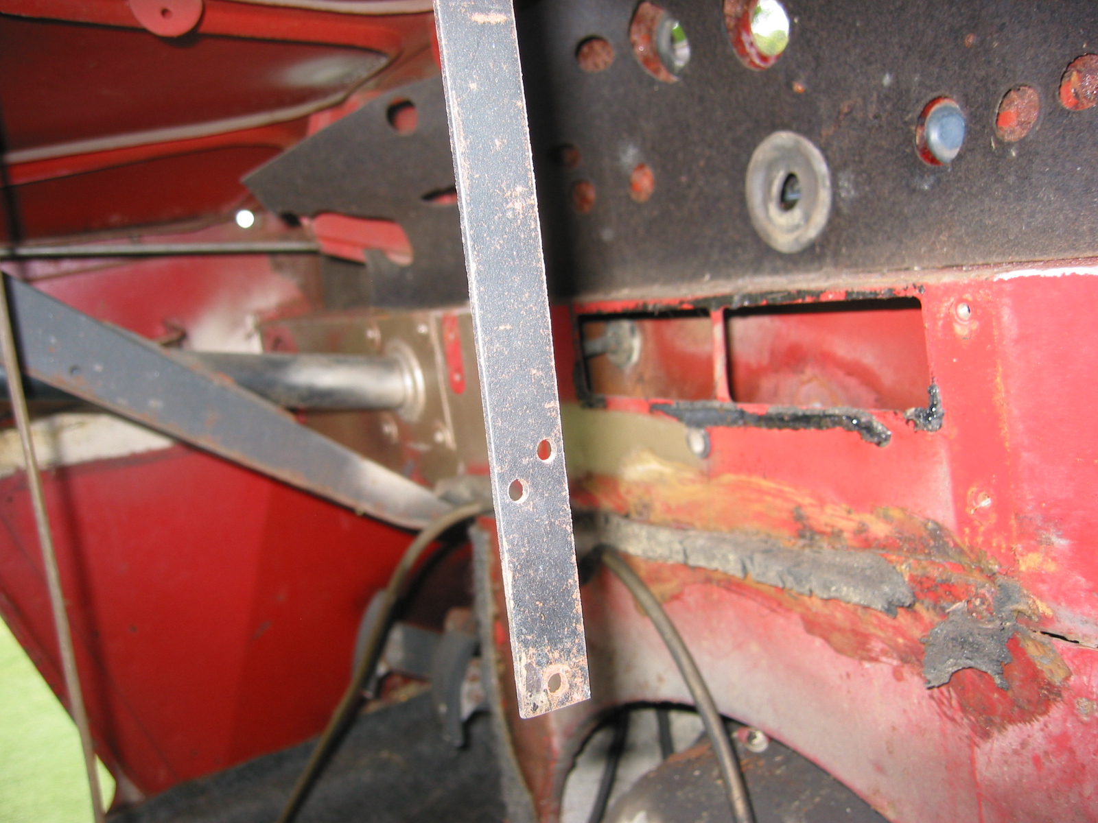
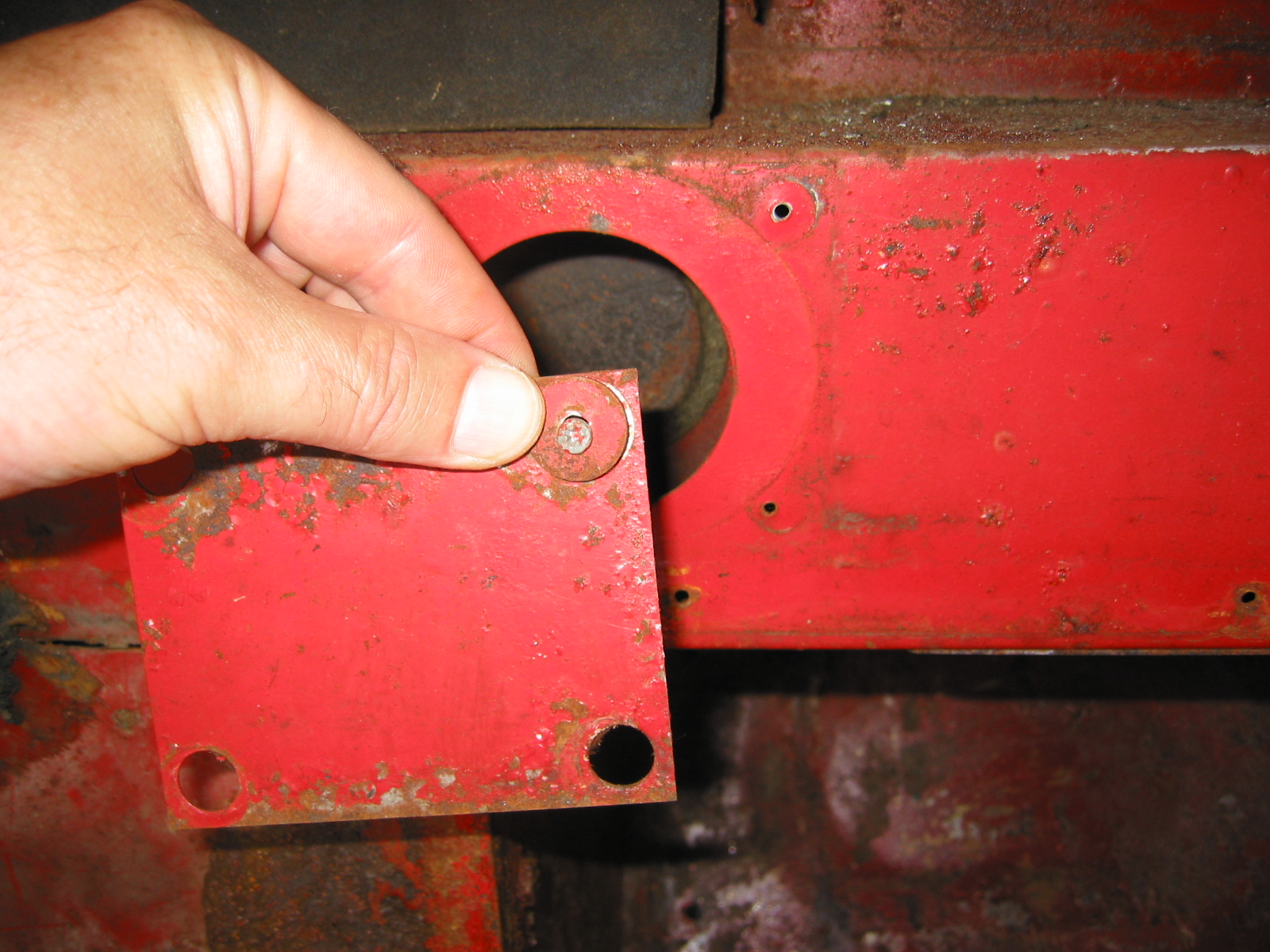
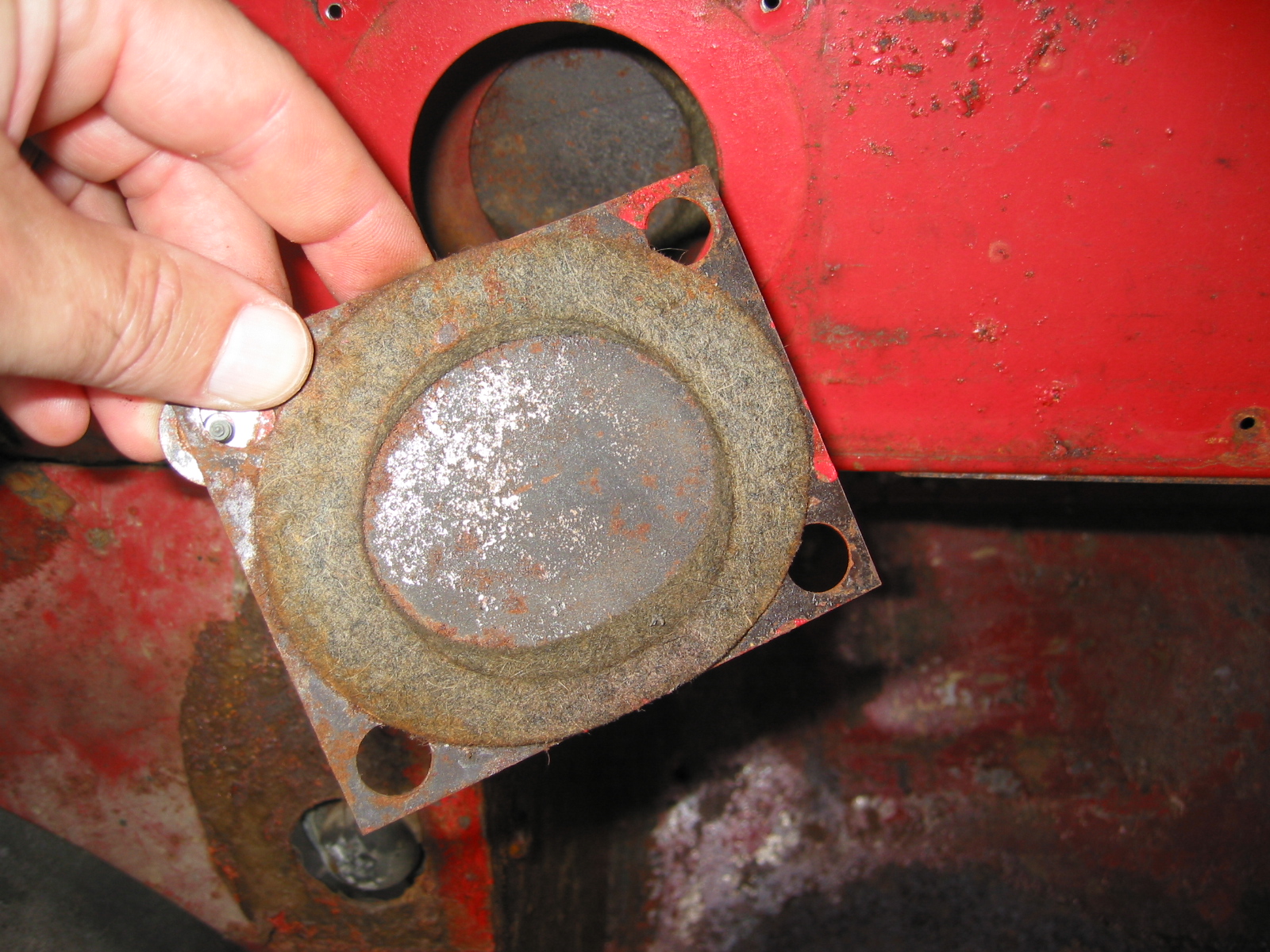
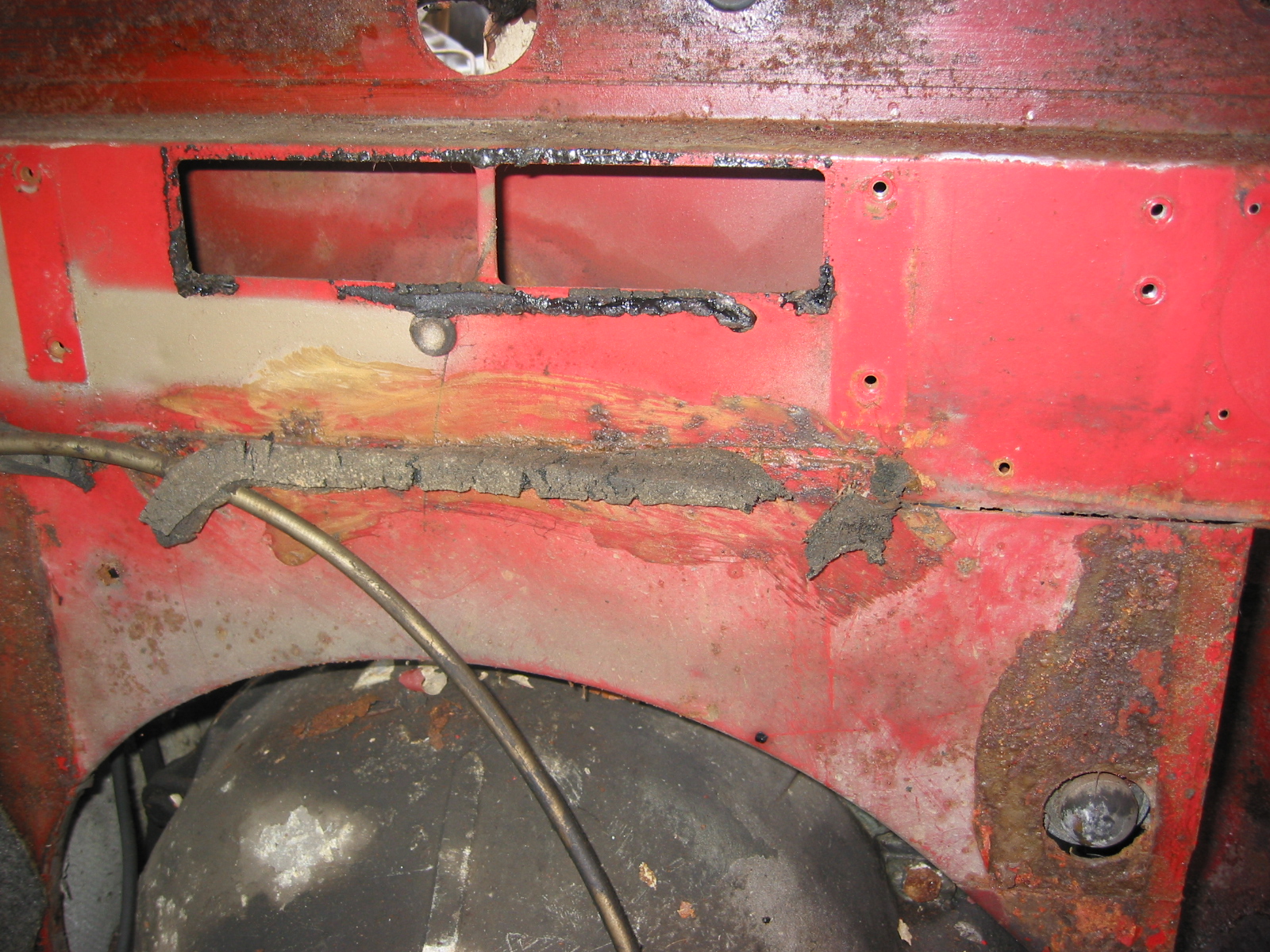
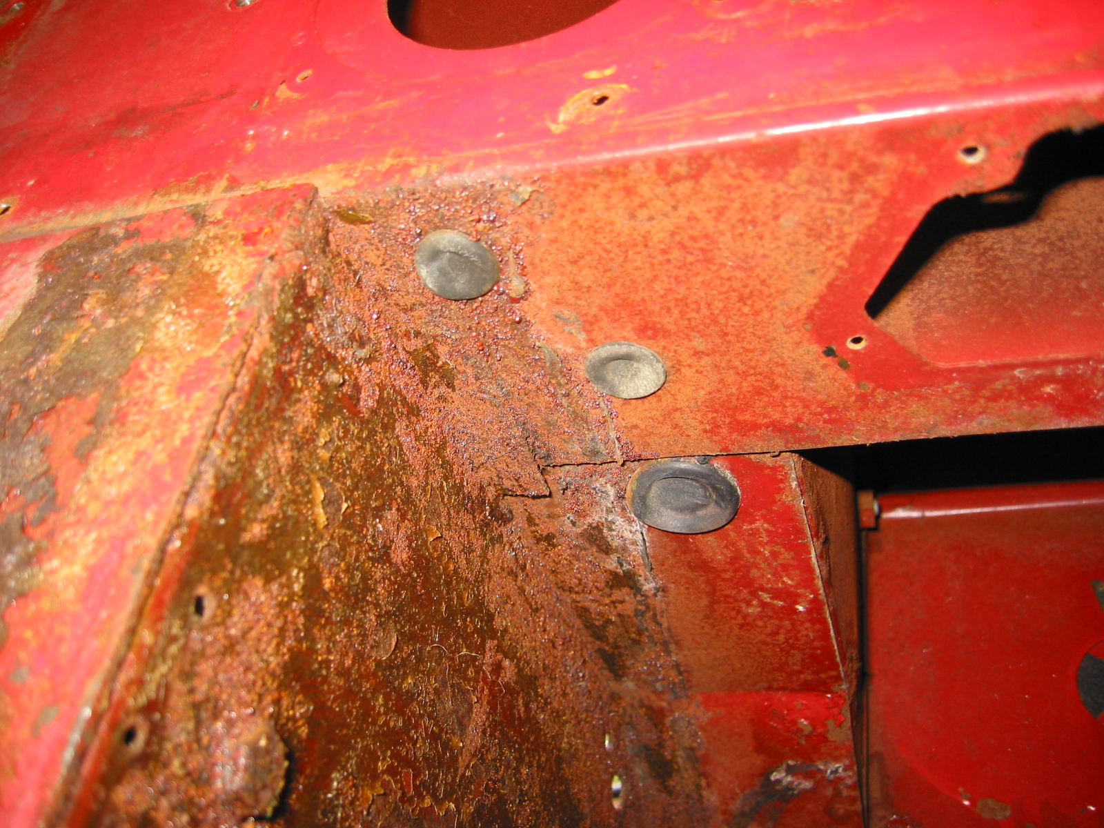
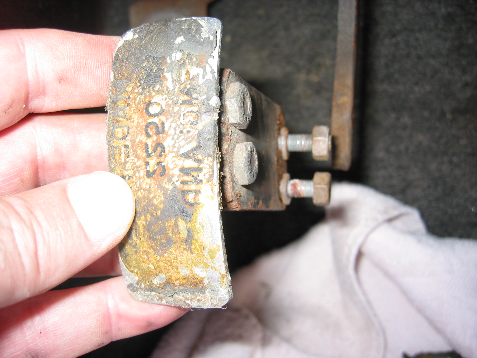
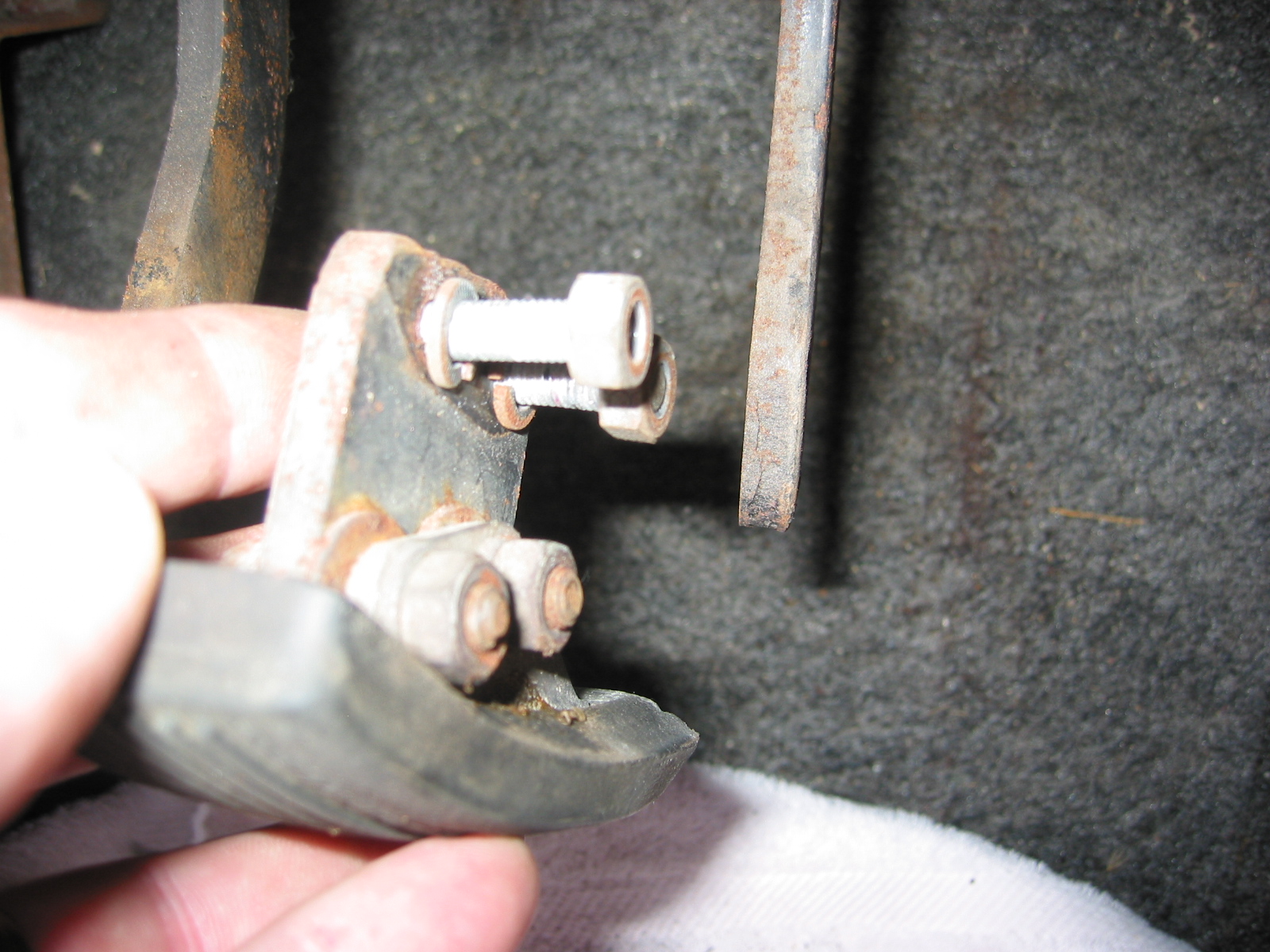
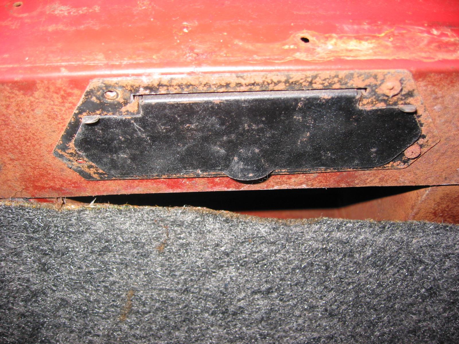
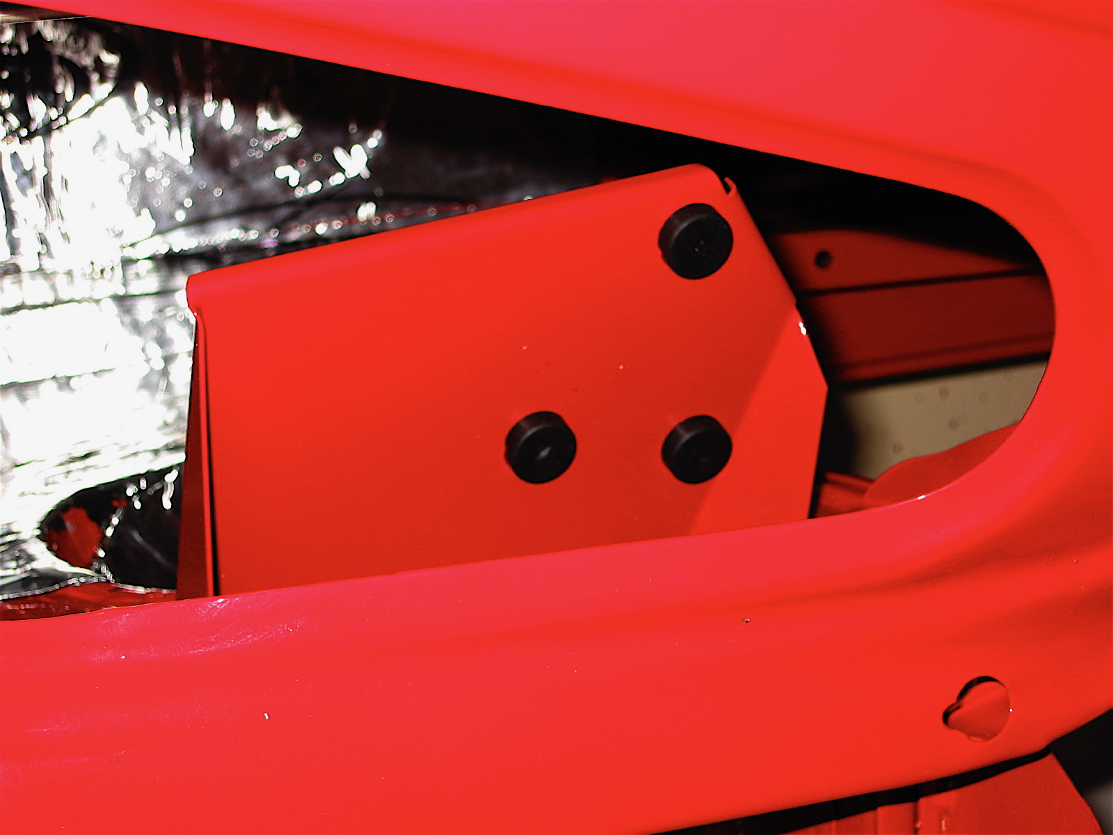
Because of family schedules we celebrated Christmas (gift giving) on Christmas Eve this year, so Monday, Christmas afternoon was devoted to garage work on the Healey. I continued with the installation of the Dynamat Extreme and finished the right side pedal assembly box. I will wait until a little later to finish the dynamat in the interior. The blanking plates were next: one plate with screw clip nuts for the right side master cylinders, 2 plates to cover the steering shaft holes for RHD (one in engine compartment and one in the interior), and finally two plates with the hole for the steering shaft grommet on the left side of the car for LHD cars (again one in the engine compartment and one in the interior). I painted all the flat washers and screw heads for the plate installations.
Blanking Plate 1
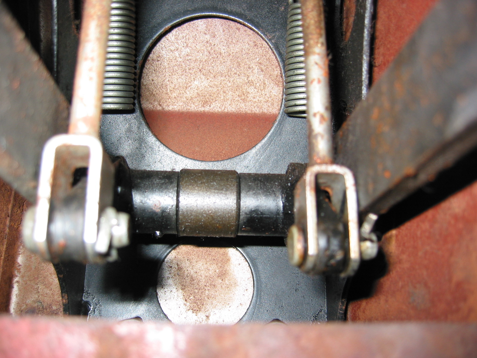
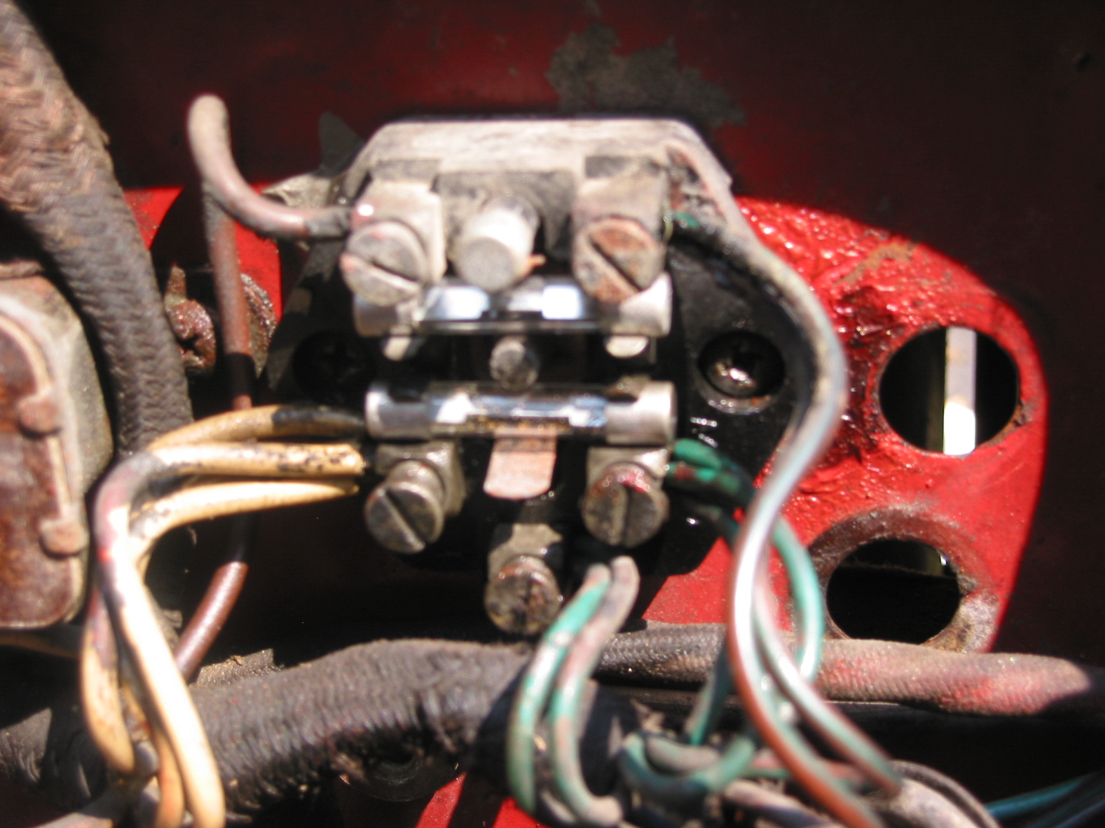
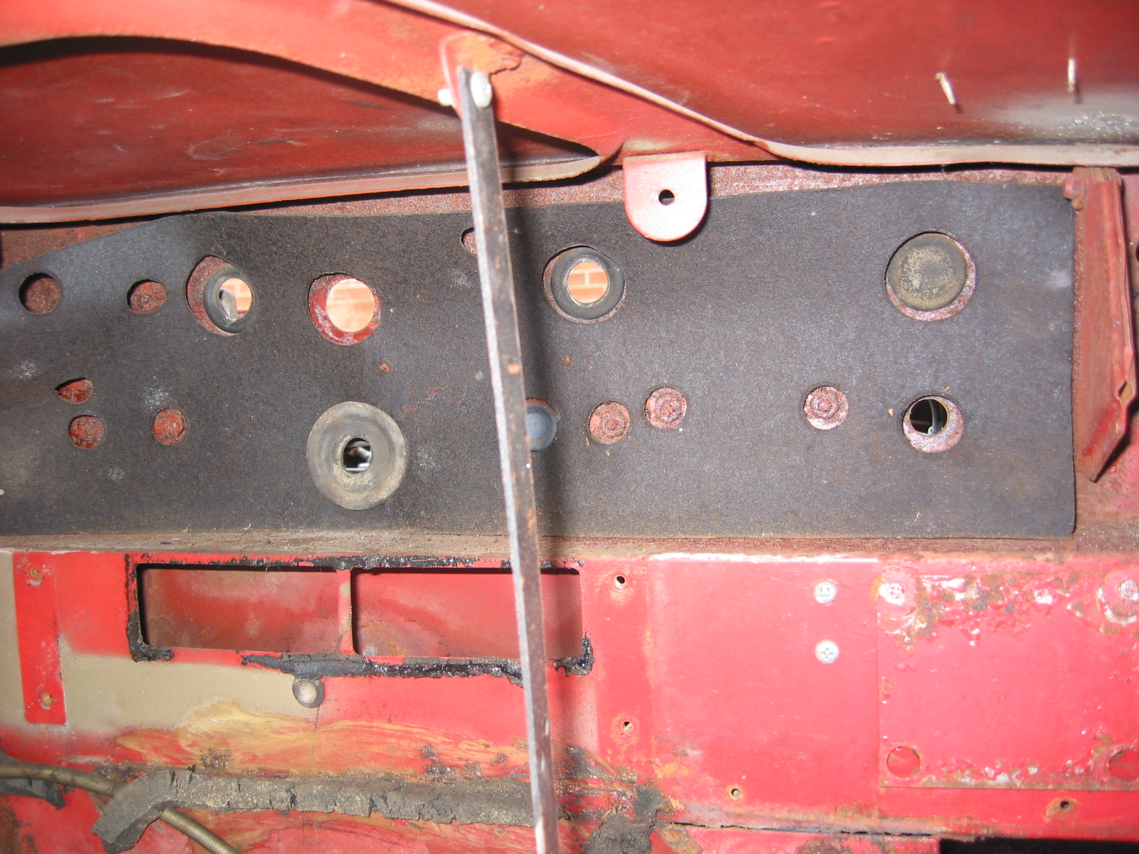
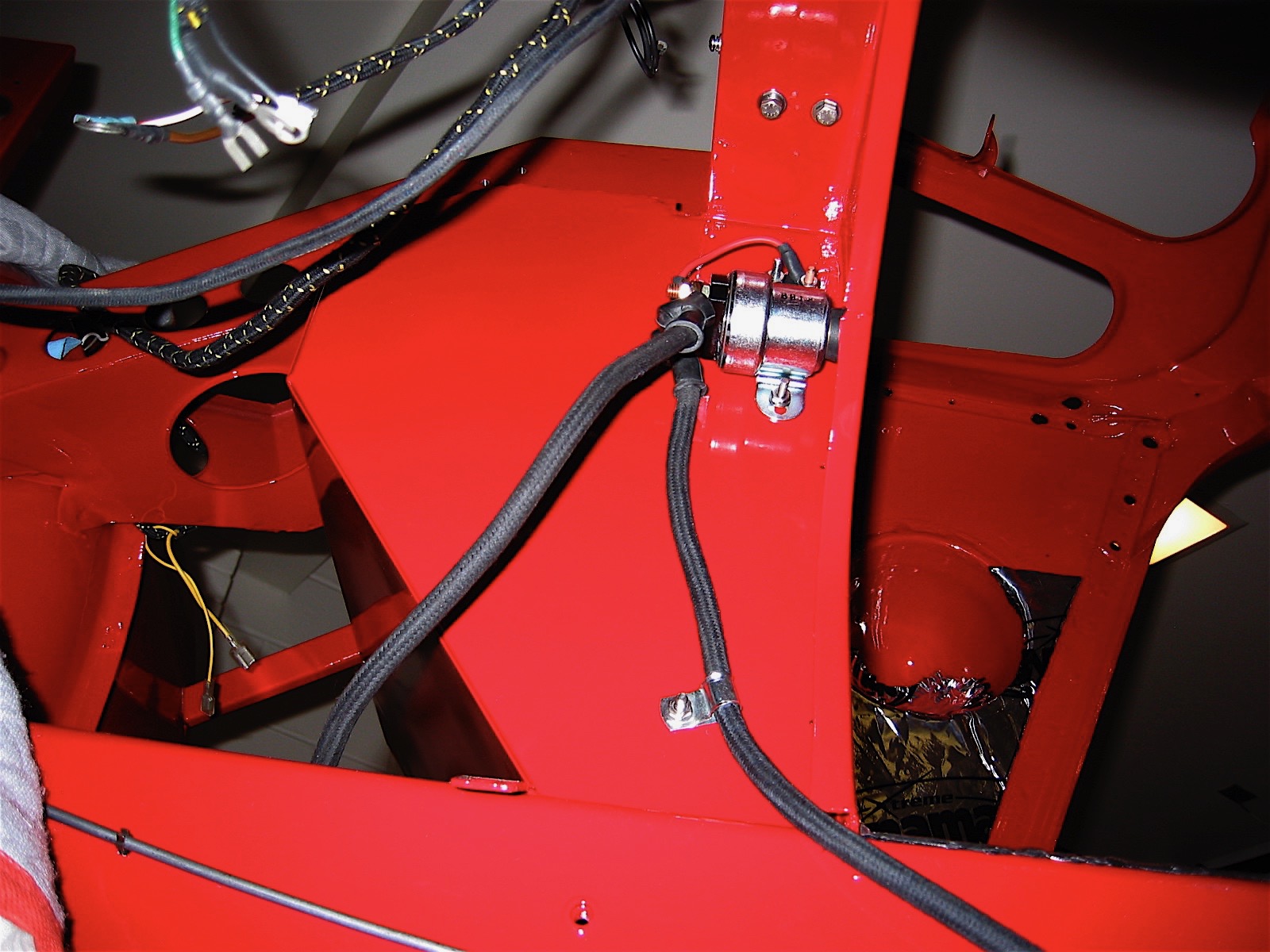
I then fastened each of the hot air outlet interior door assemblies and thebulkhead flange bezel. Followed by the fuse block, the double clip for the clutch and brake lines from the masters to the fluid reservoir, the flasher canister and the new flasher relay.
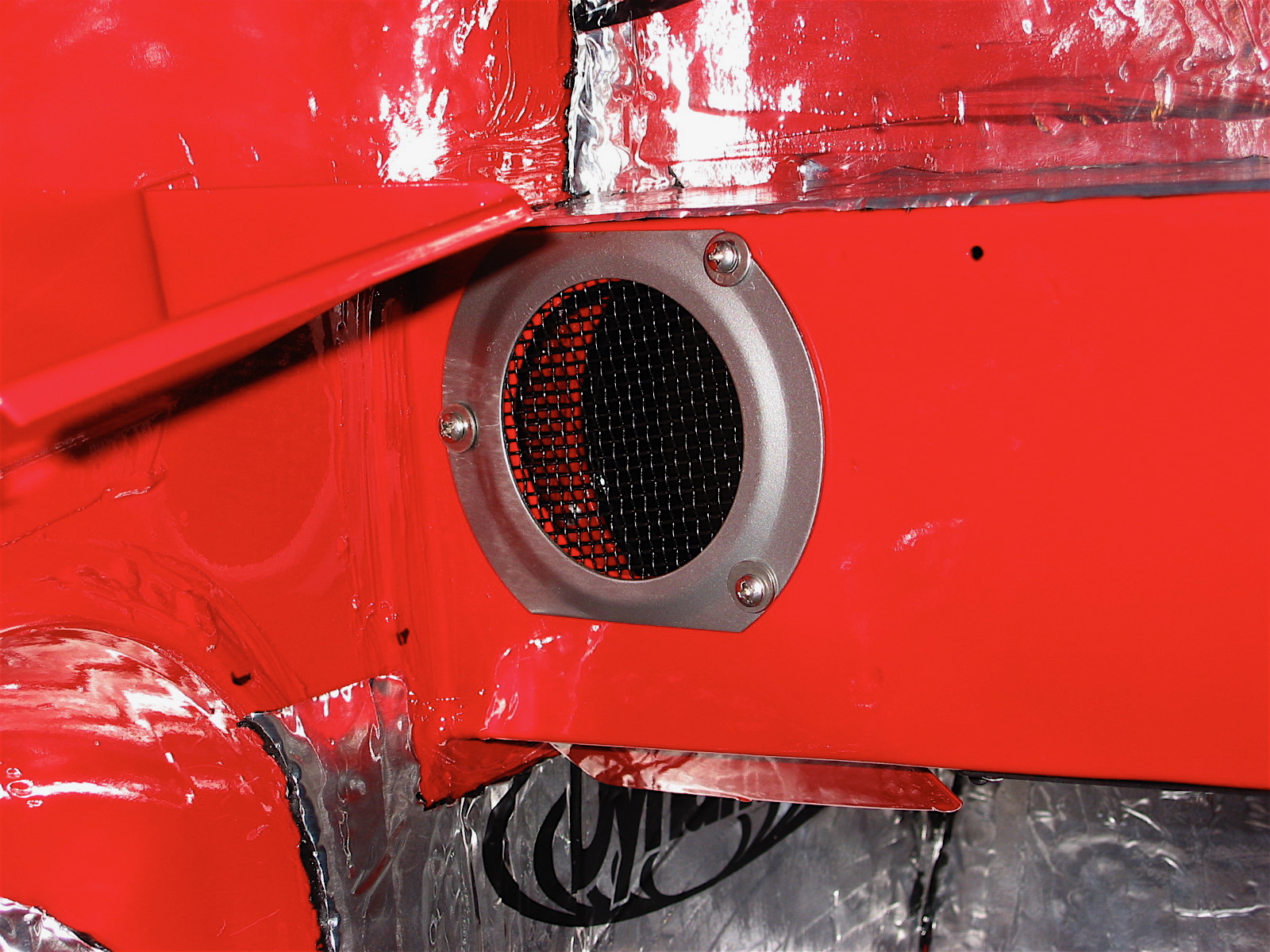
Bulkhead Flange Bezel

Vent Doors
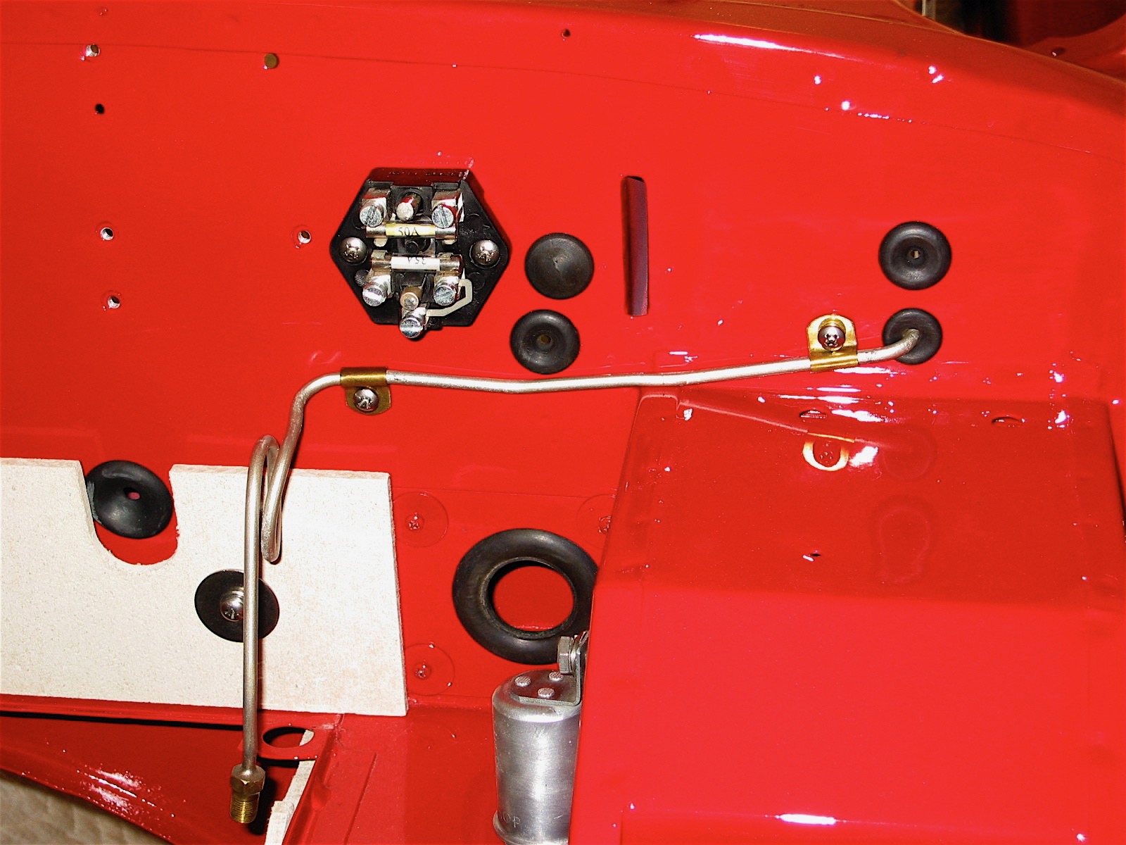
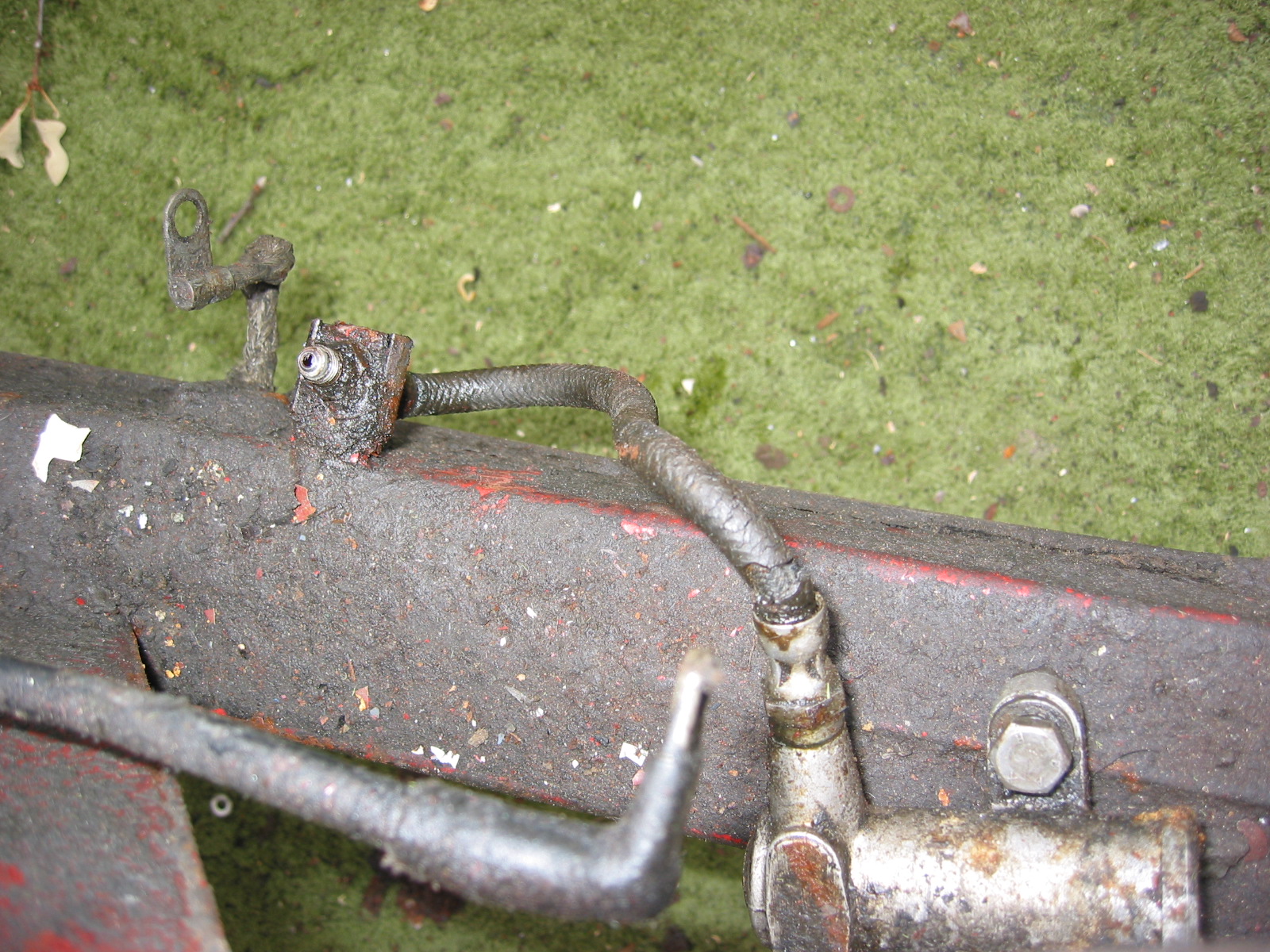
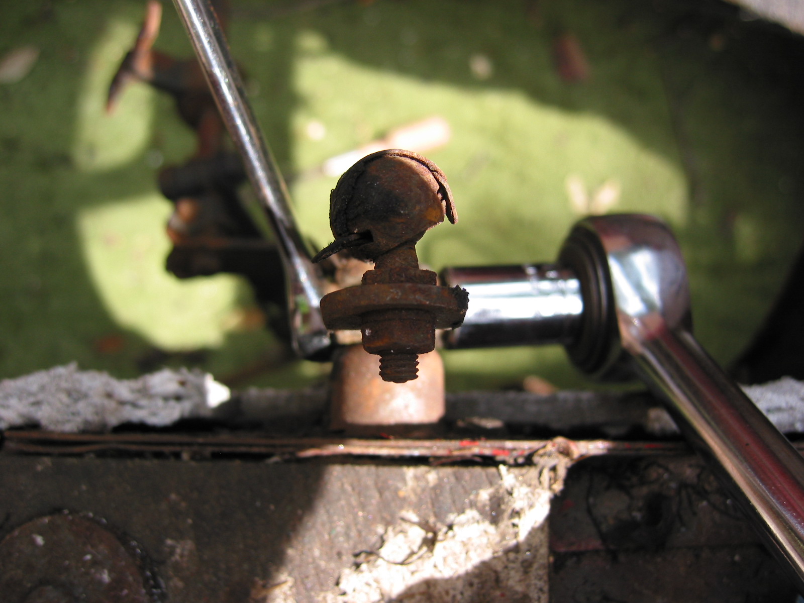
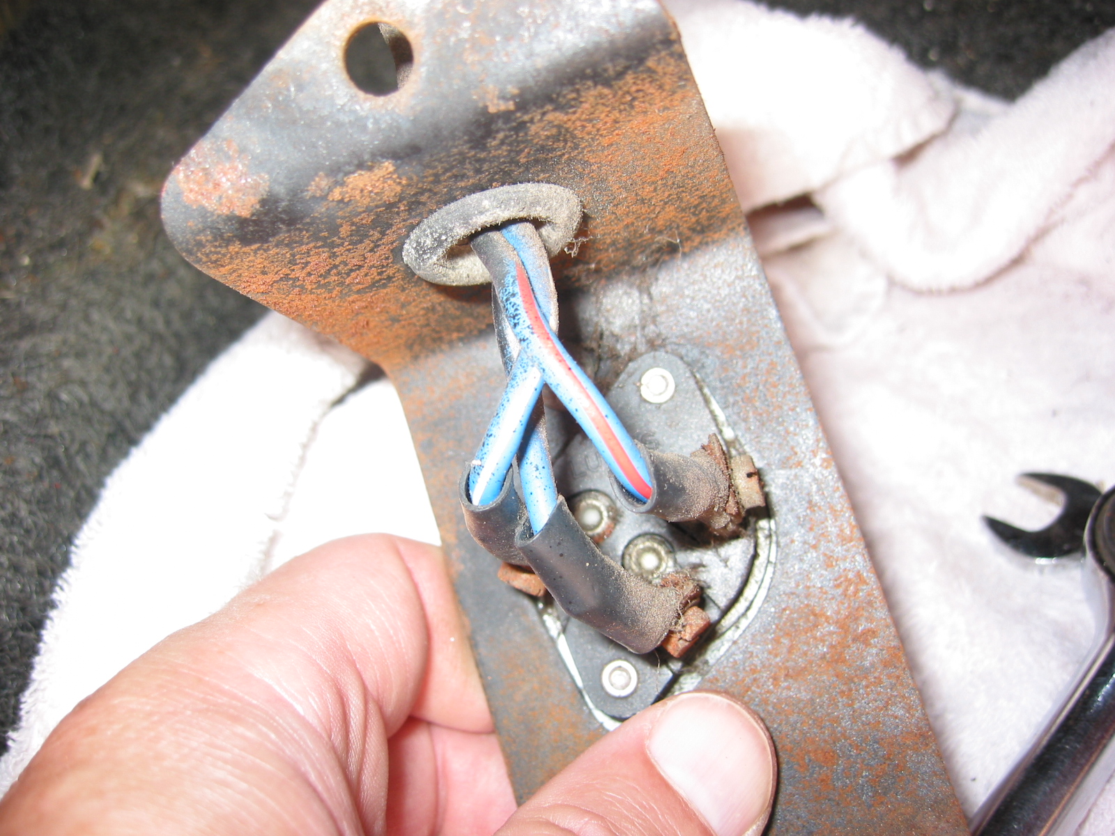
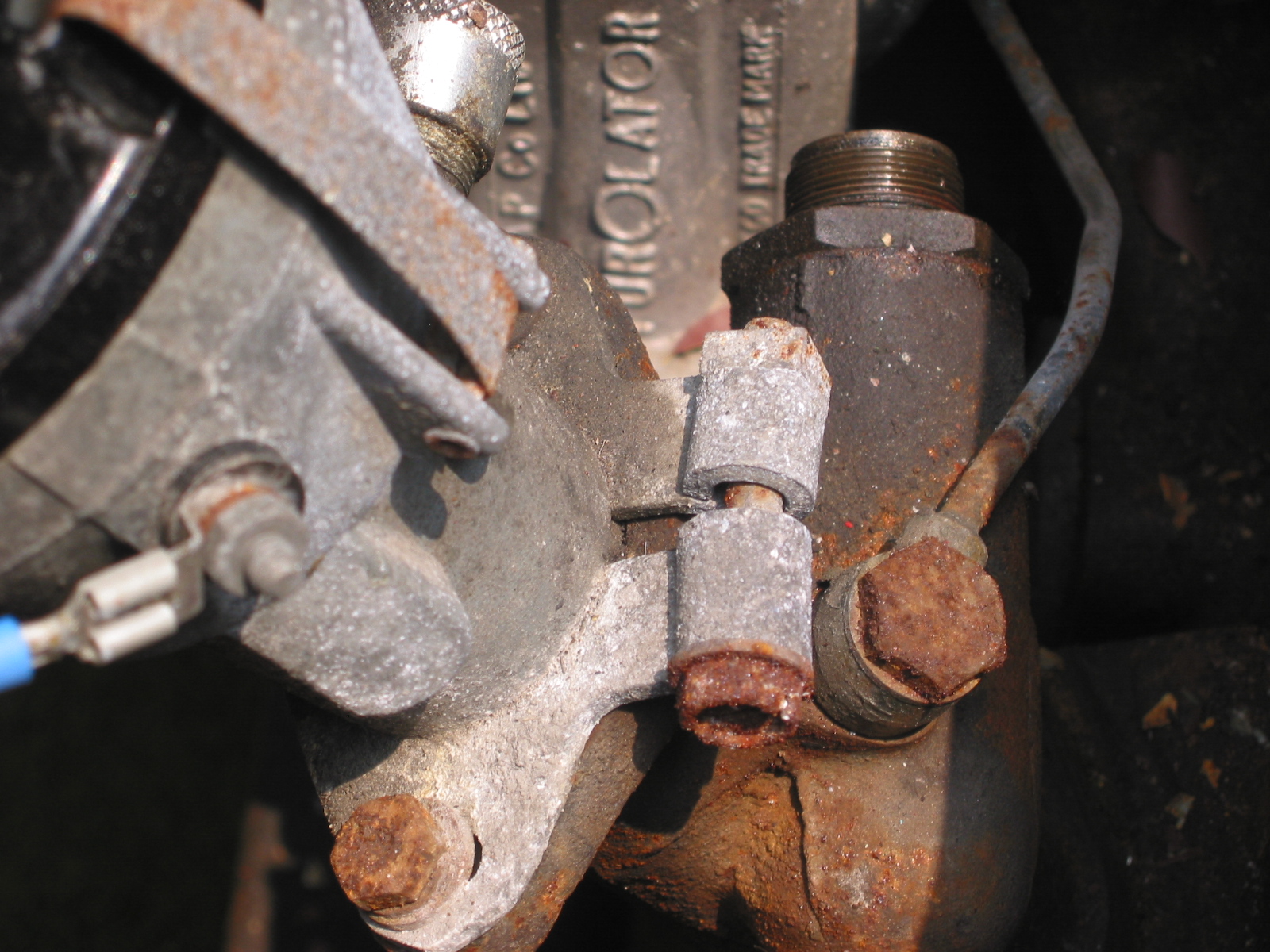
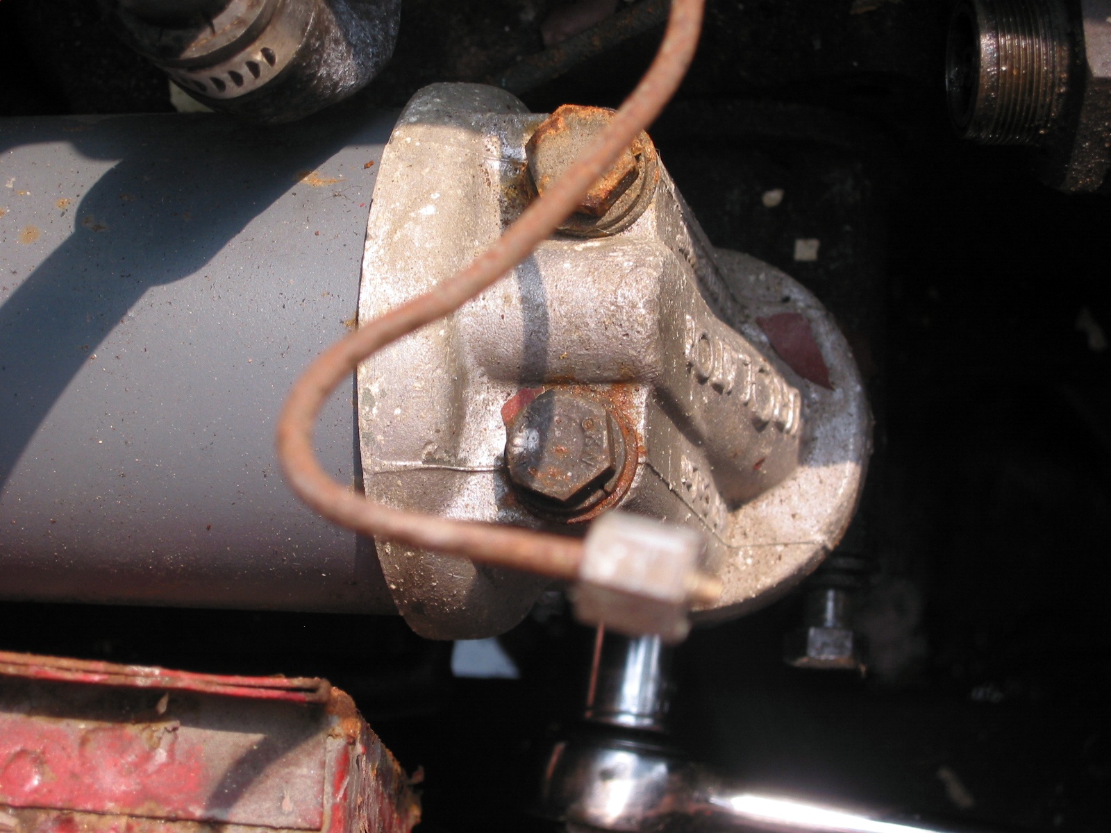
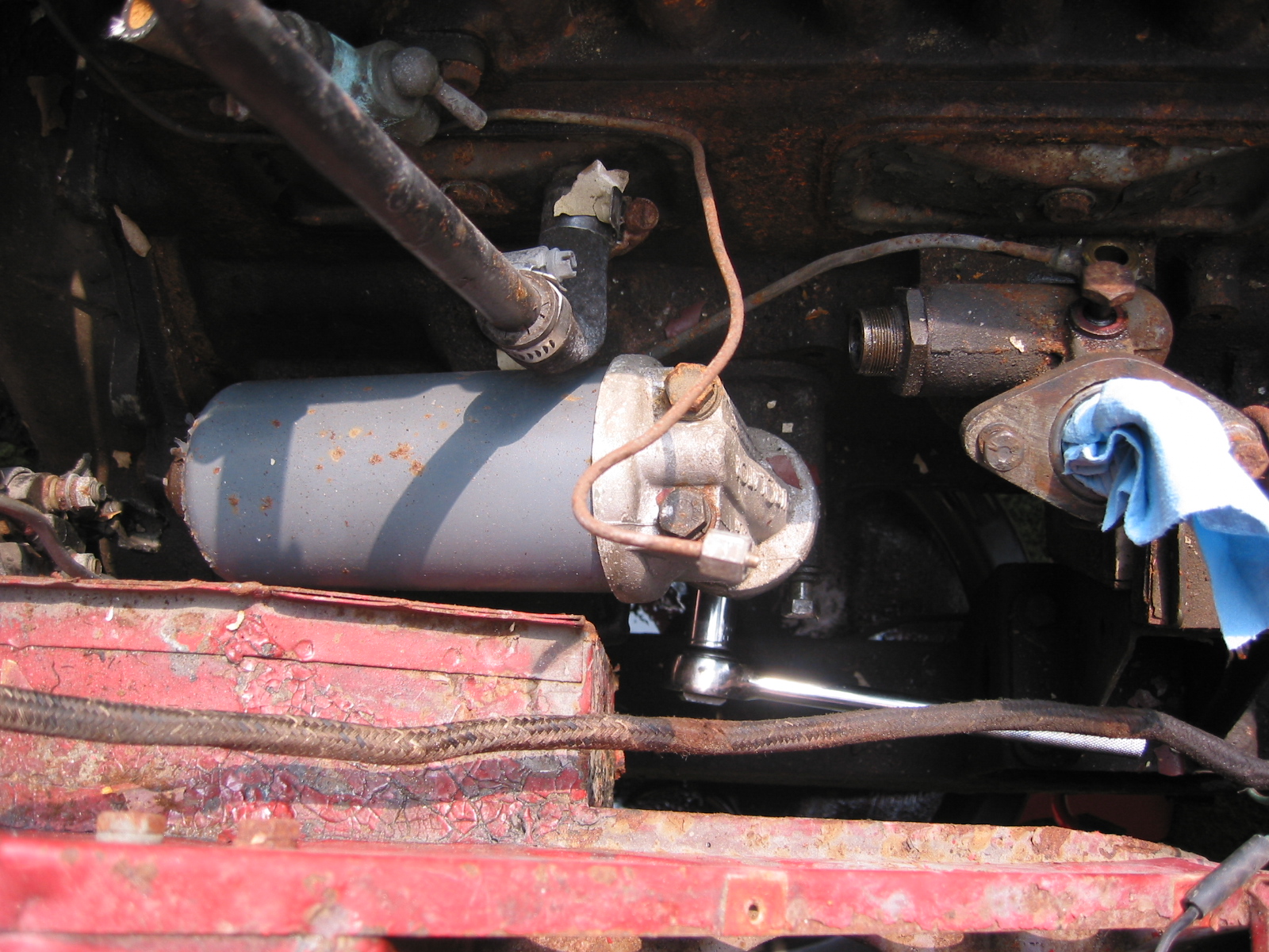
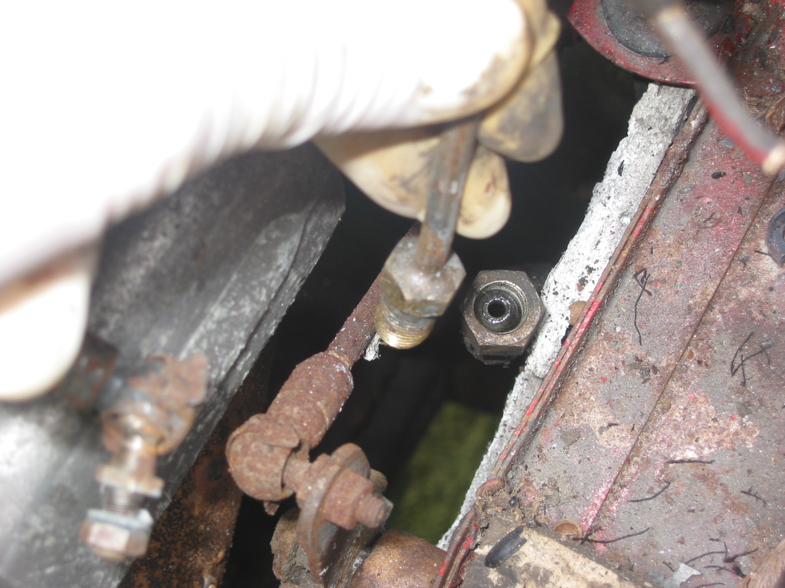
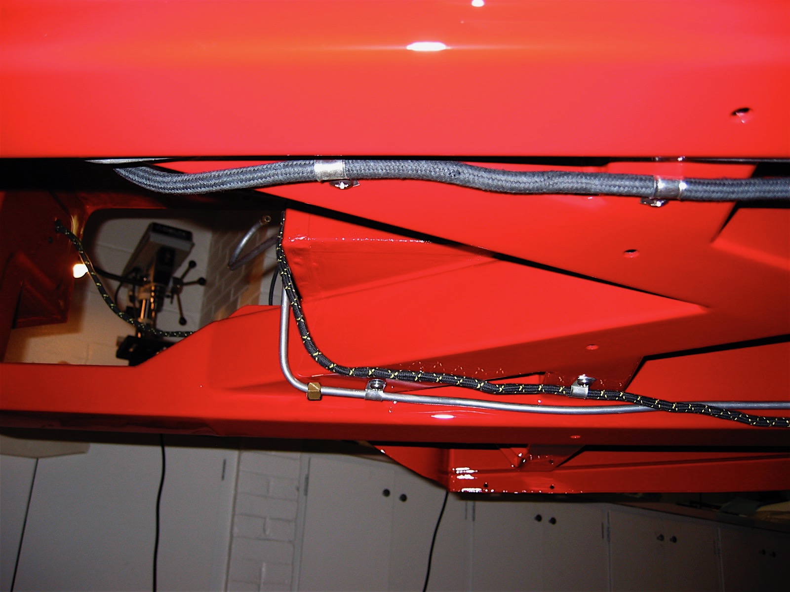
Fuse Block and Oil Gauge Line
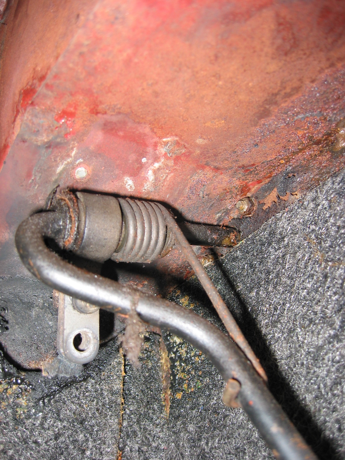
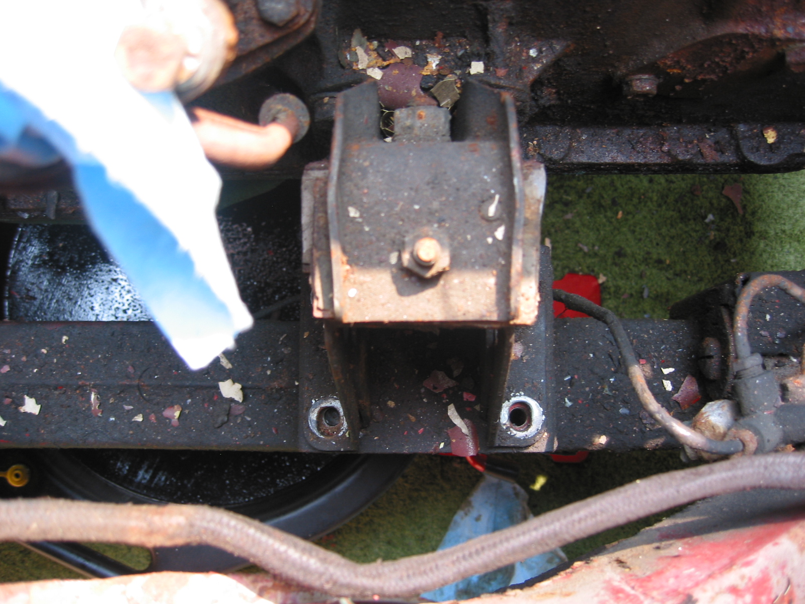
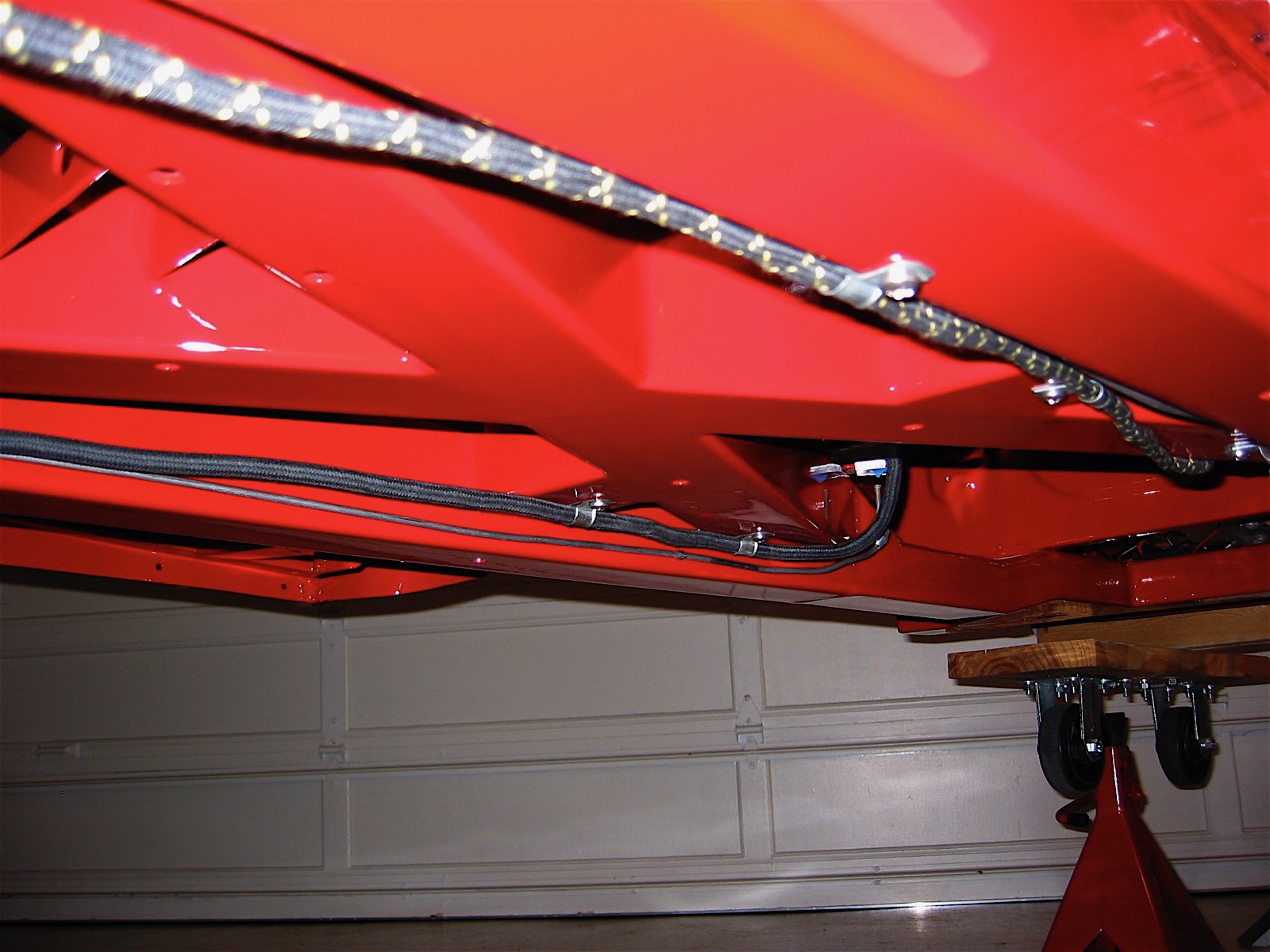
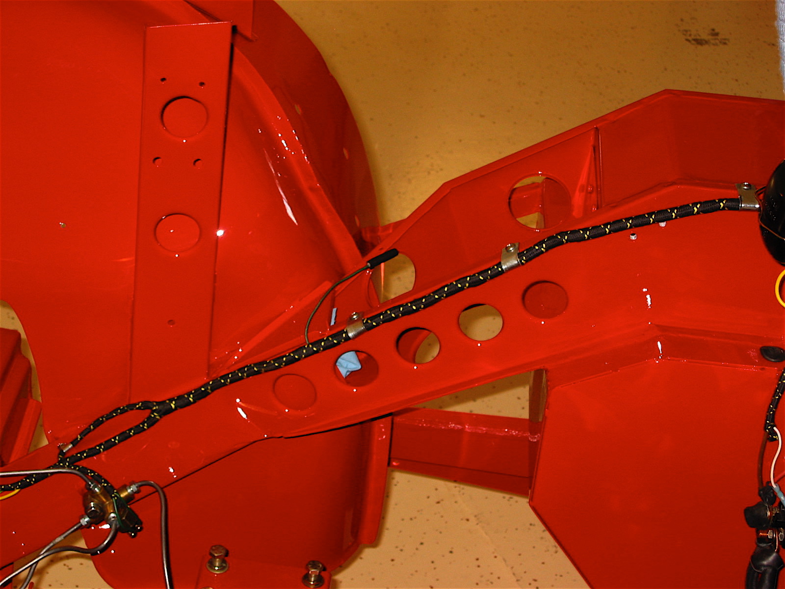
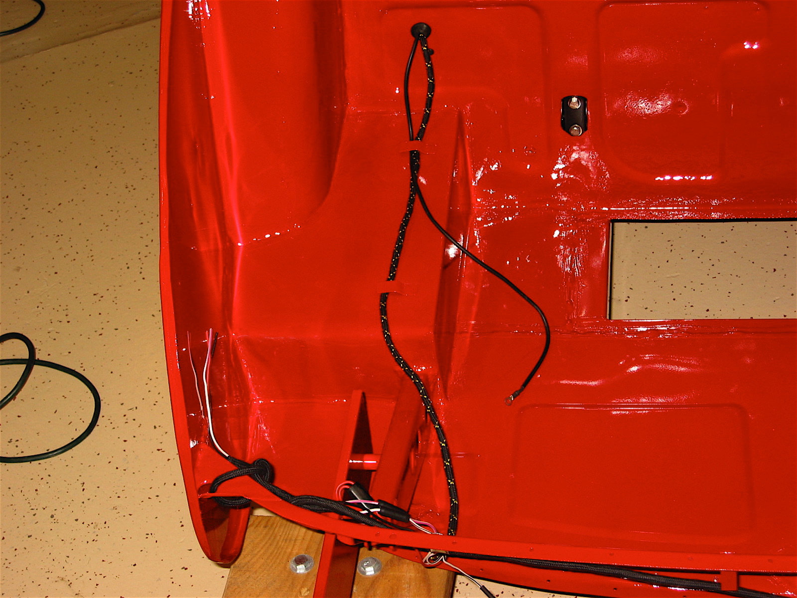
Well, it is a new day and I am ready for some new challenges. I will get started on the battery cable from British Car Specialists and the wiring harness from British Wiring, Inc. I pushed the harness through the firewall grommet from the interior and separated the strands. I decided to focus on the under car runs first, so after jacking up the car on stands I installed the harness wire that goes to the boot for the fuel pump, fuel sender and rear lights. I skipped the clip attachment to the bump box until I have the rear axle in place.
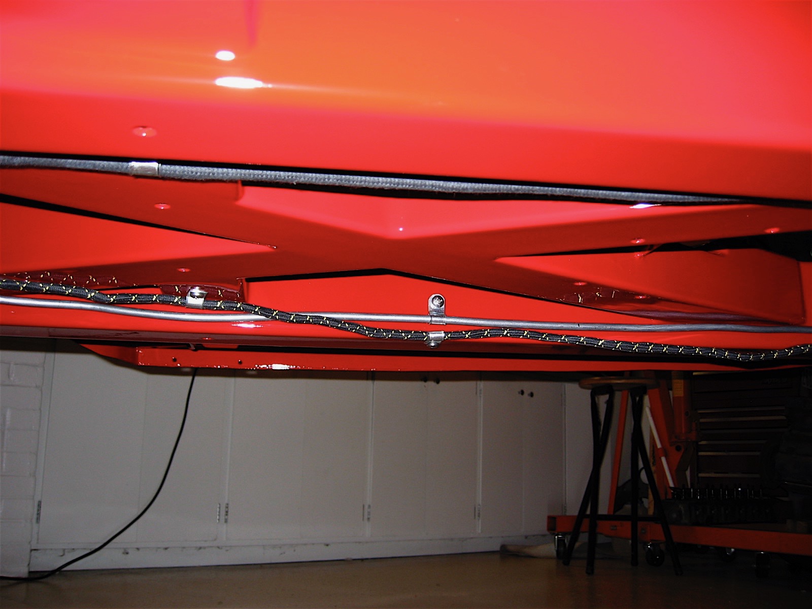
Wiring Harness 4
Wiring Harness 5
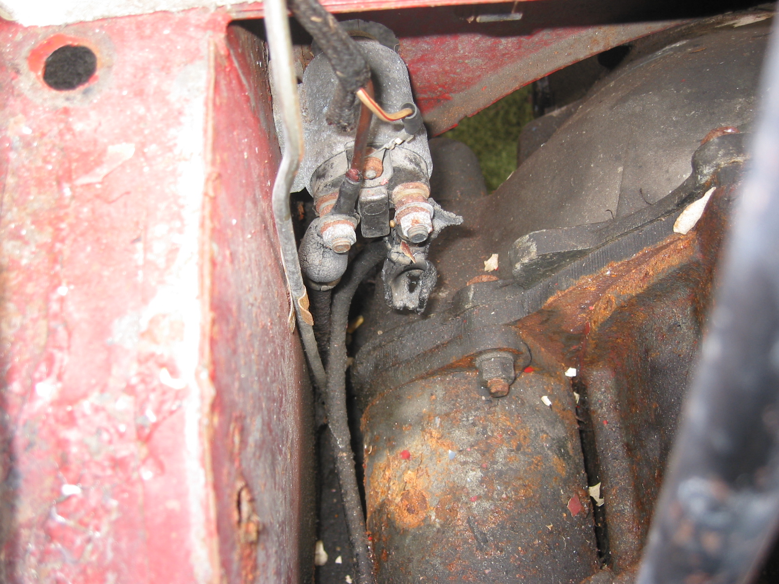
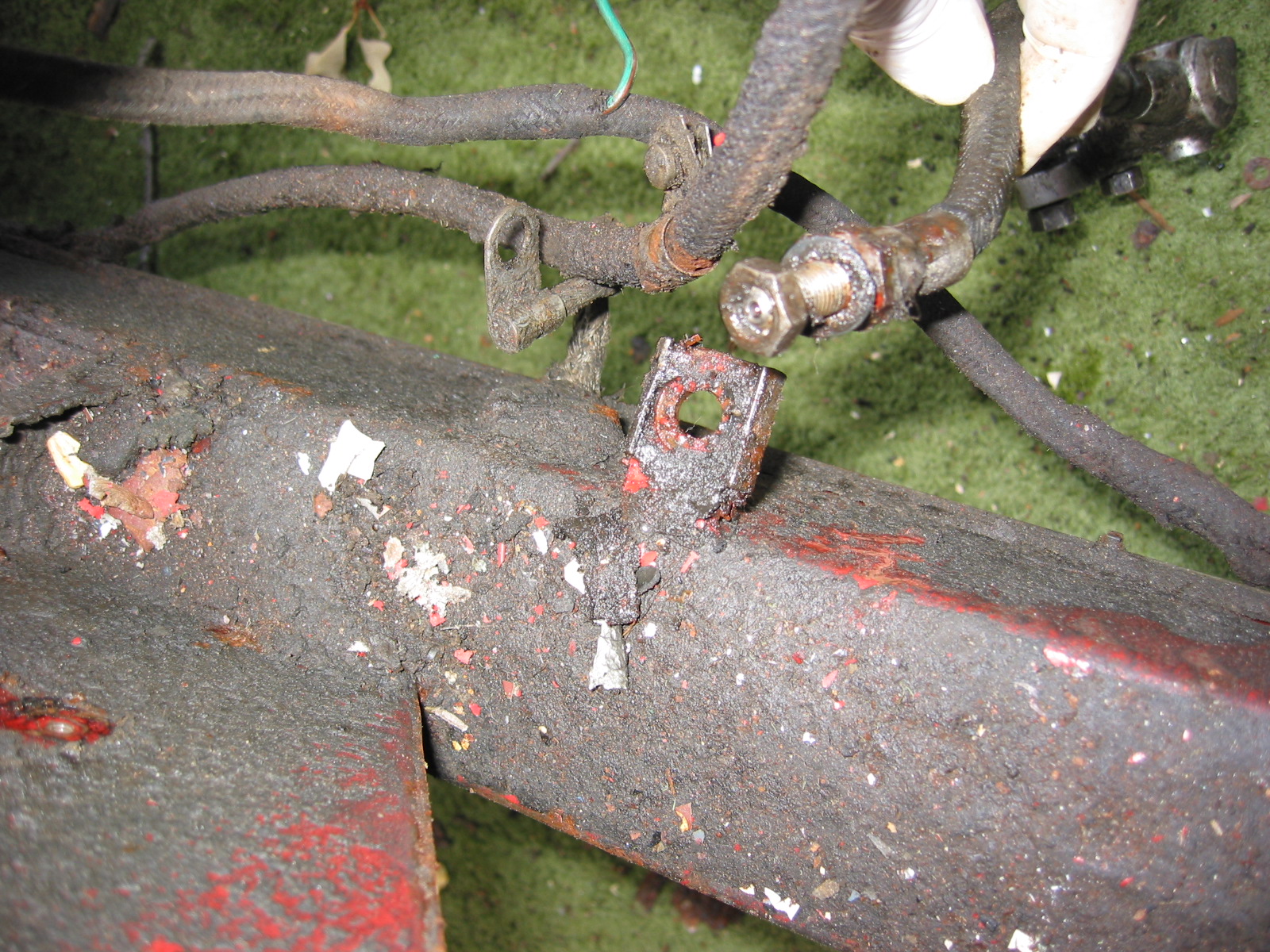
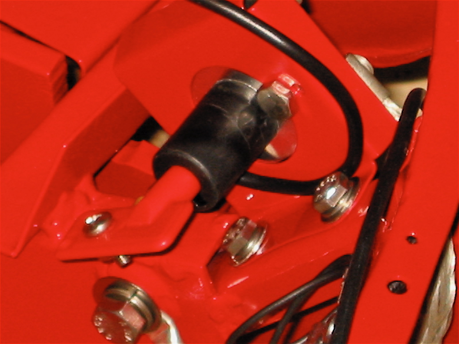
Next I shifted my attention to the battery cable. I got it in place and quit for the day. Tomorrow will be dedicated to connecting the harness under the bonnet and in the boot.
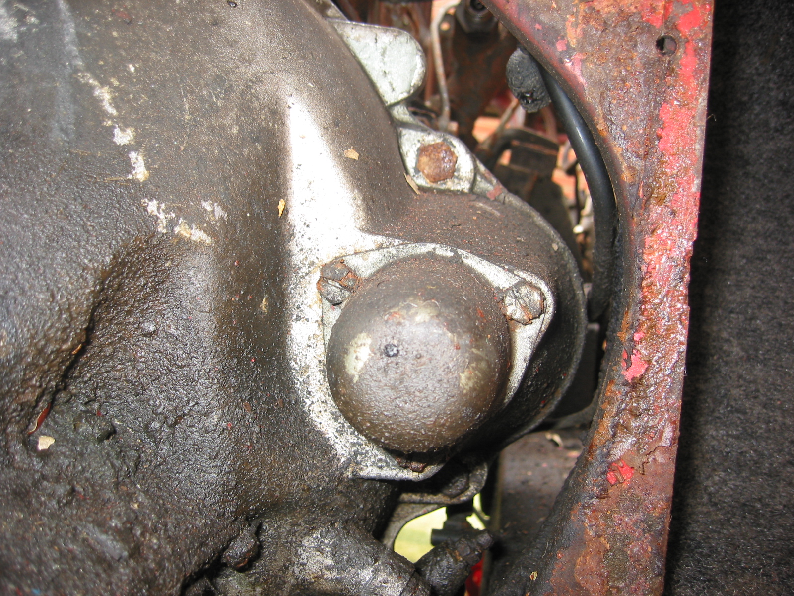
Battery Cable 1
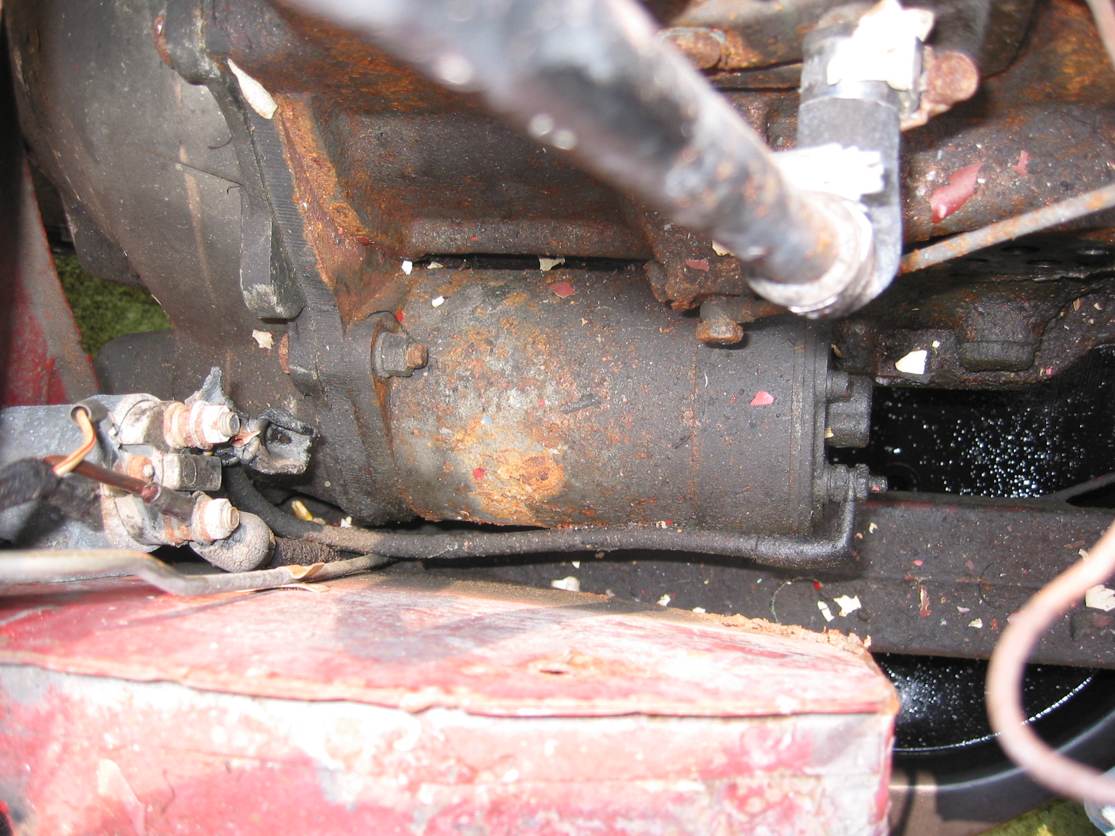
Battery Cable to Starter Solenoid
Harness left side
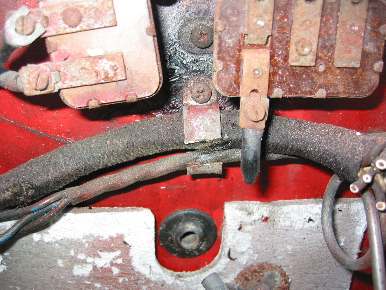
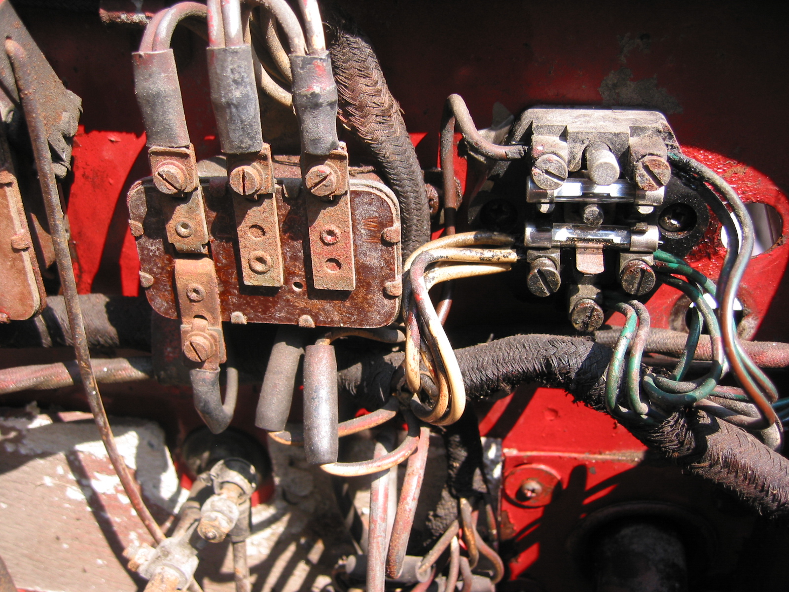
Wednesday was a good day. I started with the harness on the left side of the car. I secured the harness in the engine compartment with the appropriate zinc fastening clips and connected the wires to the fuse block, the flasher canister, connected and then threaded the dip switch mini-harness through the firewall, connected and threaded the mini-harness for the wiper motor through the firewall, connected the eight wires to the flasher relay box, and connected the front lamp pigtails and routed the harness through the front of the car.
Fuse Block & flasher
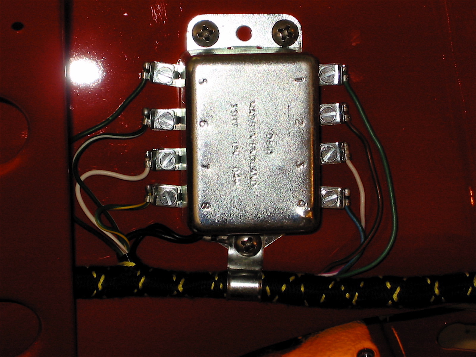
Flasher relay
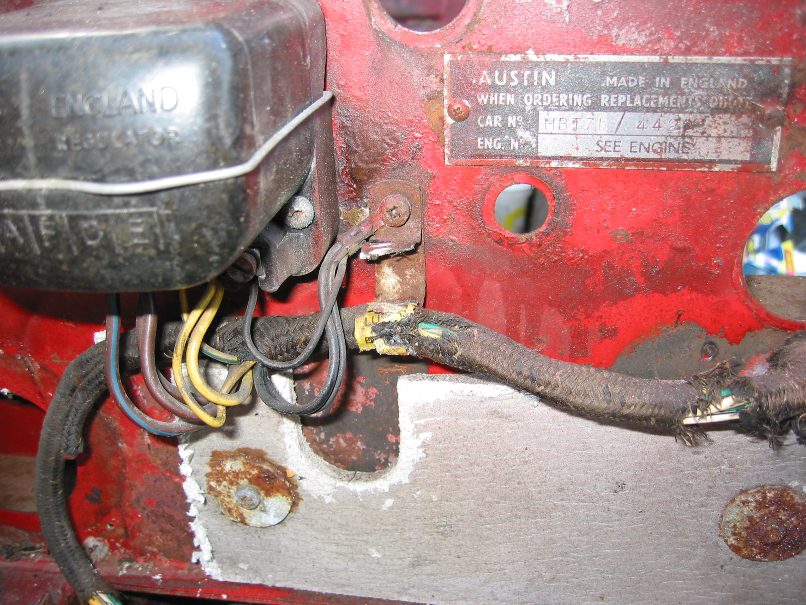
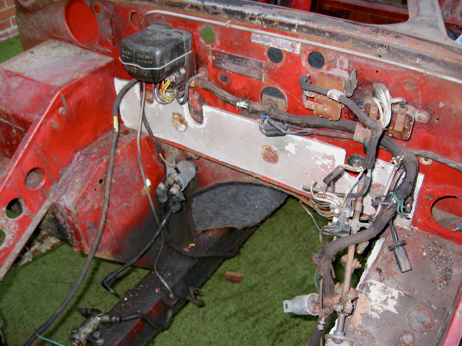
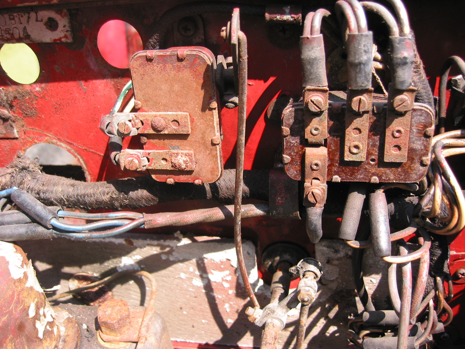
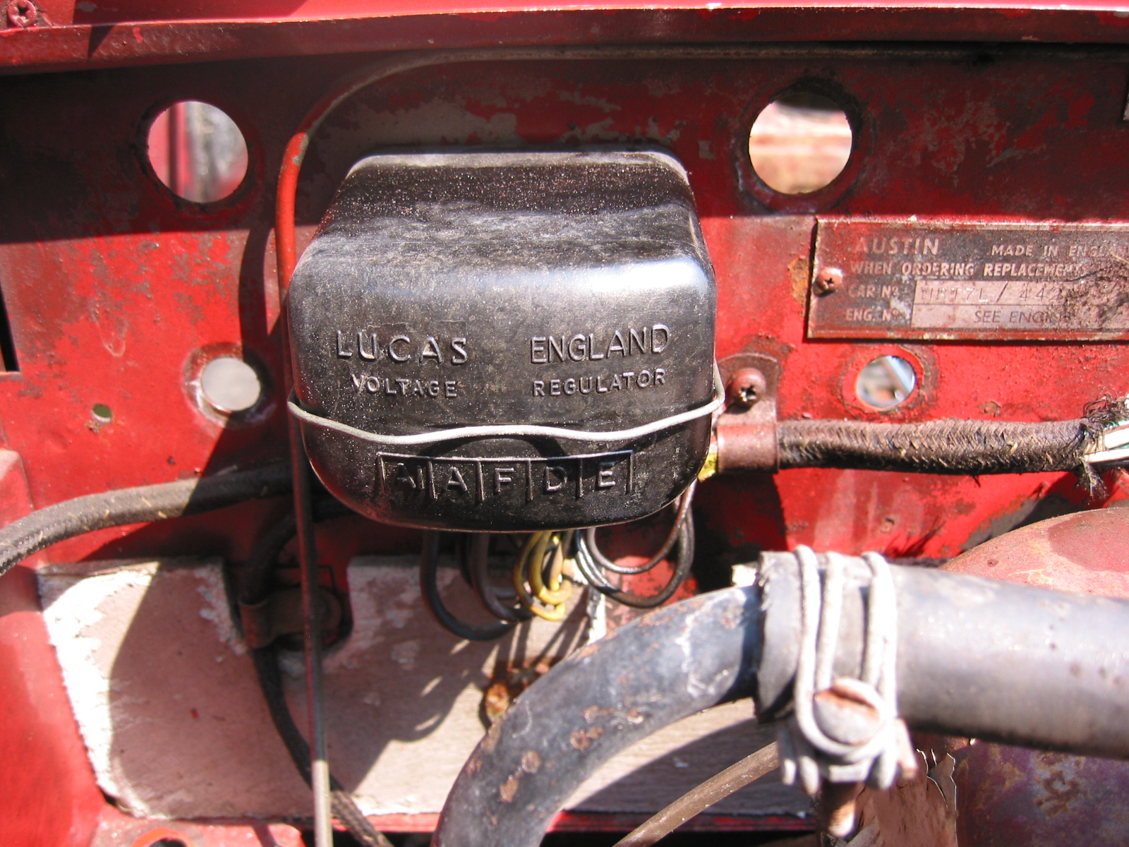
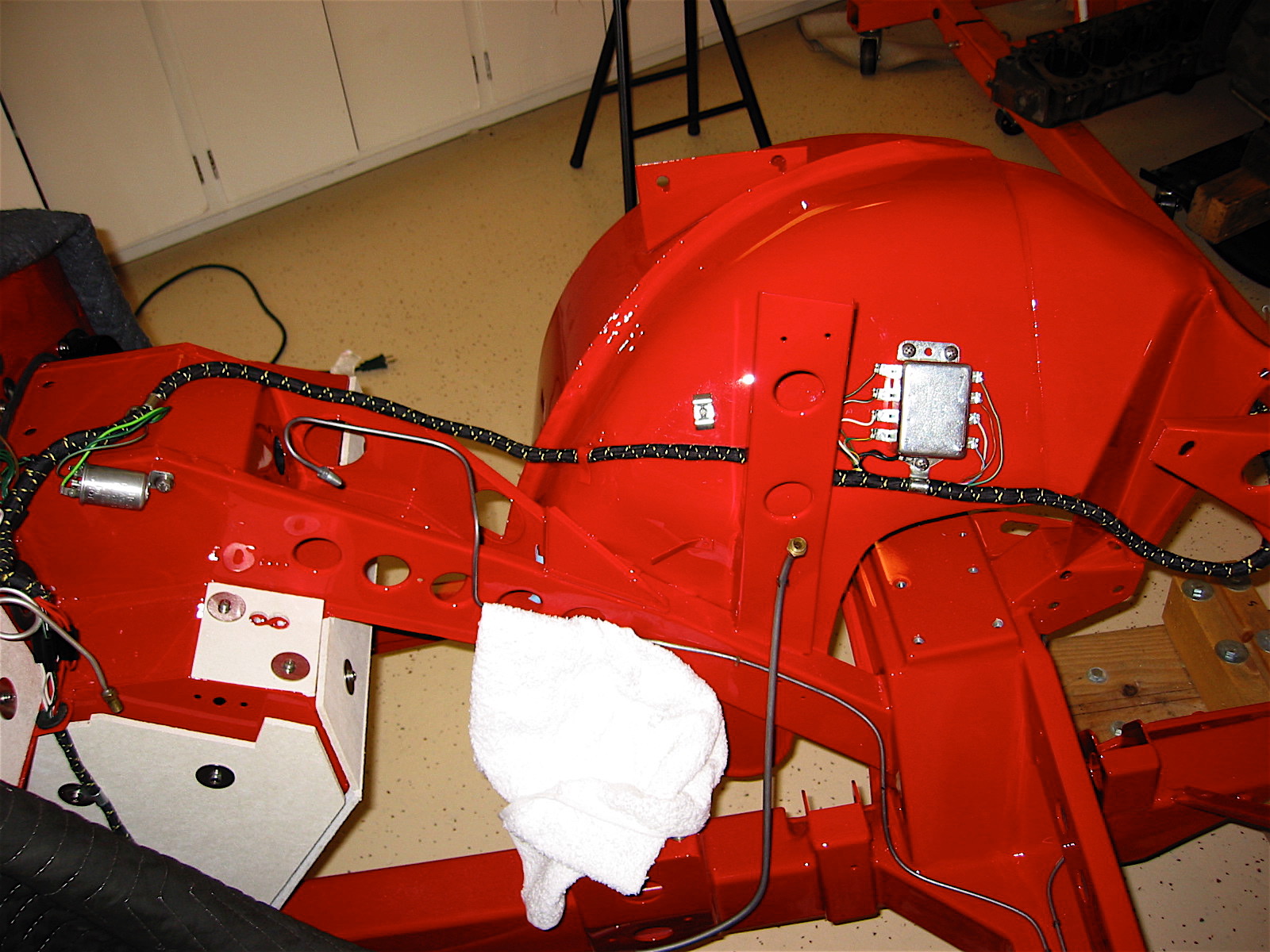
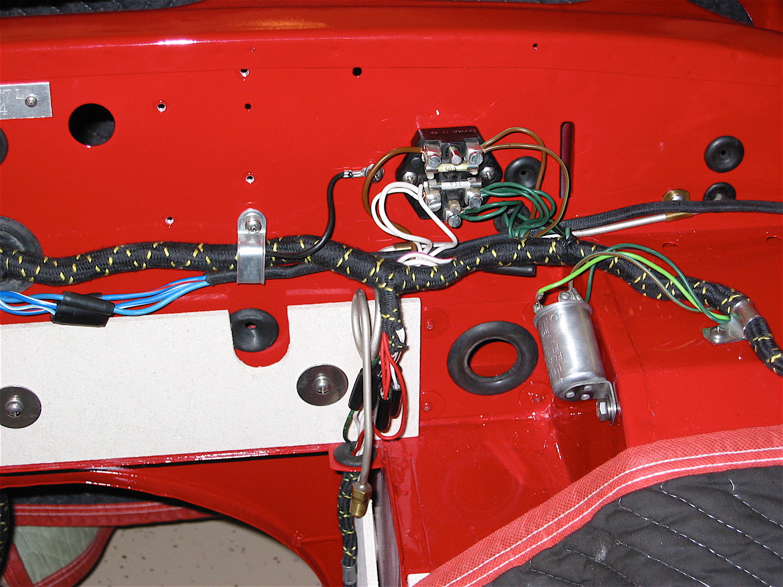
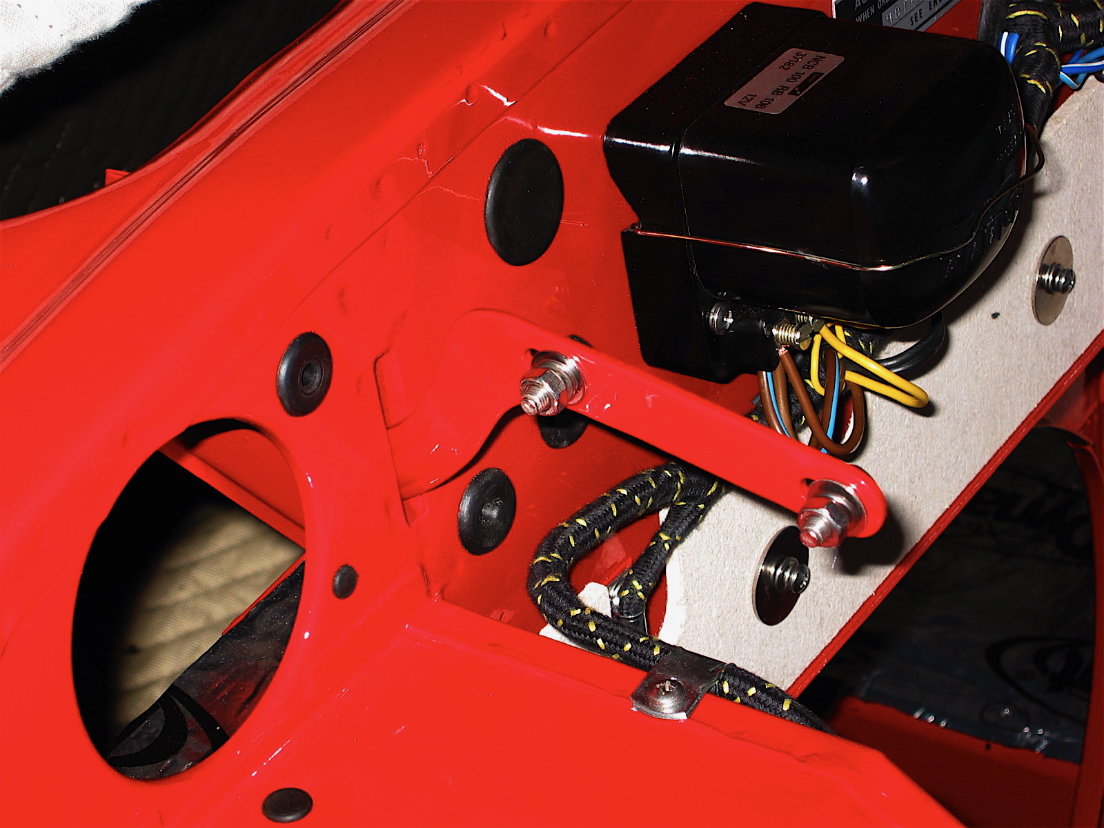
Then I shifted to the right side of the wiring harness. I modified the voltage regulator box to accommodate wiring for an alternator. This is done by cutting out the connectors in the back of the box and then connecting the three brown wires to the same post, and the two yellow wires together to another post.

Harness front view
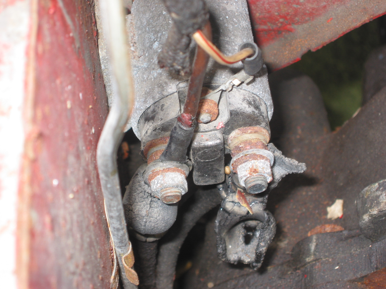
I then connected the harness to the starter solenoid, and routed the wire down the right side support. Feeders to the ignition, alternator, brake switch, and heater blower route off of the primary harness.
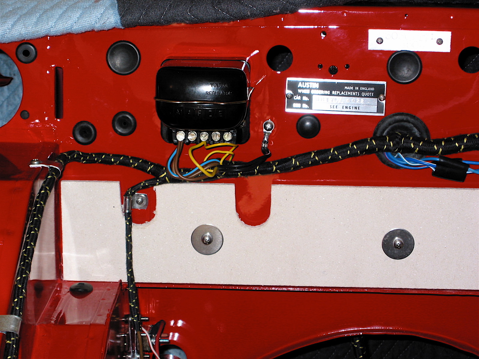
Voltage Box
Harness Right Side
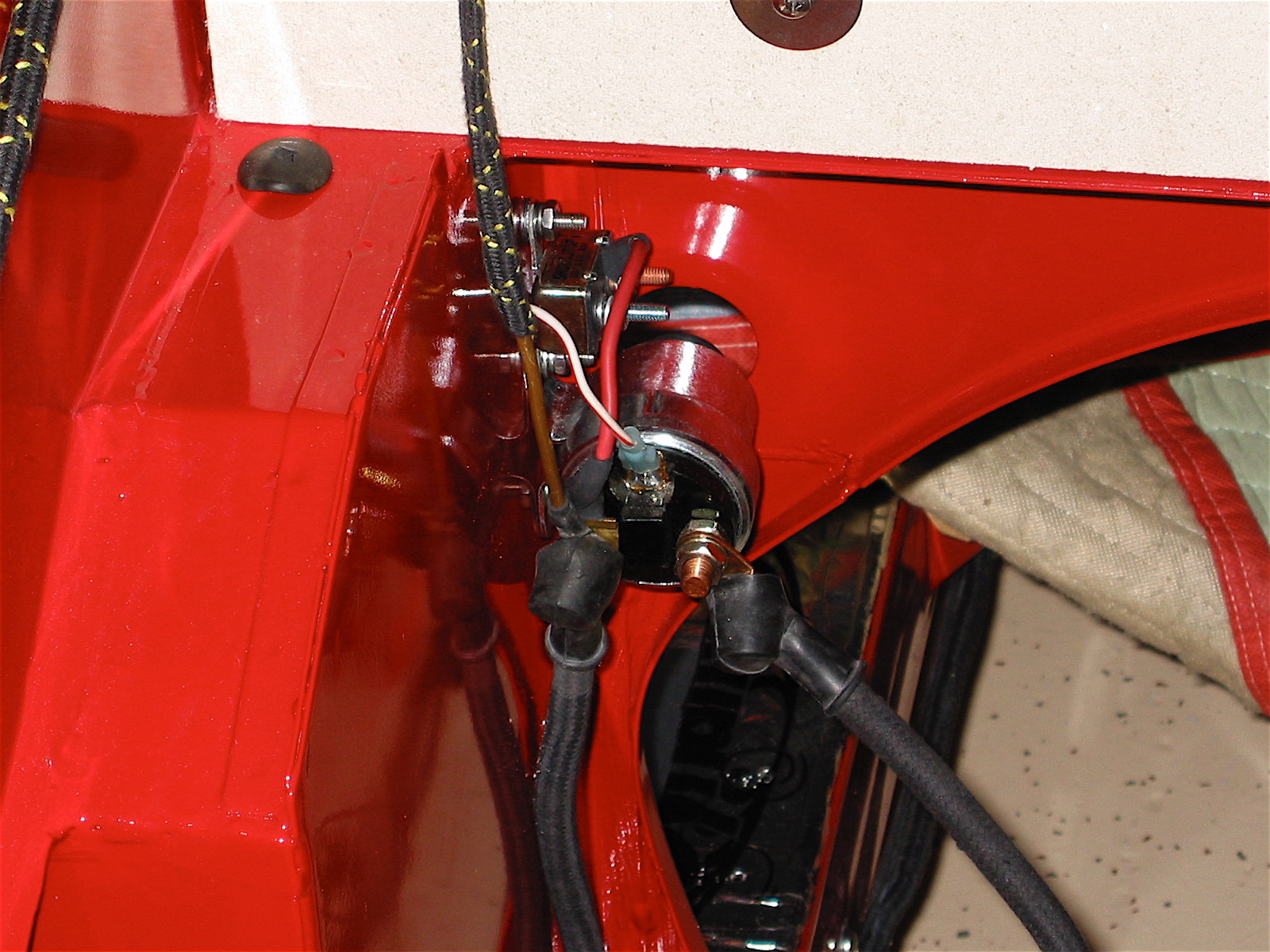
Solenoid Wiring_2
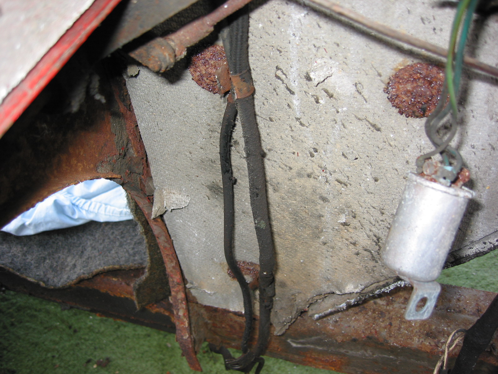
I finished the afternoon installing the battery master switch in the boot. I heard complaints from too many about the original switch so I changed to a modern variant and modified it to fit in the original housing.
Battery Master Switch
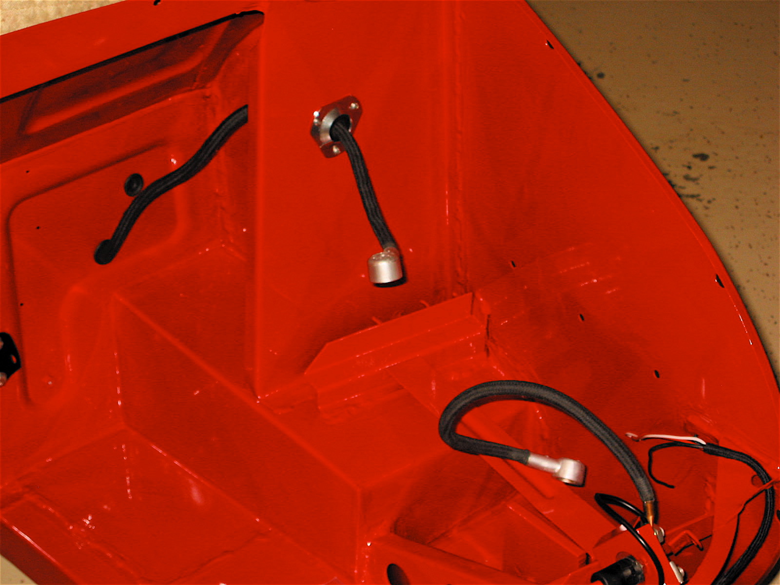
Boot Battery Cables
Boot Wiring
I then connected the ground strap, added a few rubber grommets, and routed the wiring to the back of the carwhere a rear lighting harness was connected and fastened with two zinc clips. All-in-all it was a productive day!
Back to the garage the next day, I installed my modified horn brackets and the horns. These are not the proper horns, but at least I got them painted the right color. I used Duplicolor E8800957 “Seattle Silver,” a Honda color, I believe.
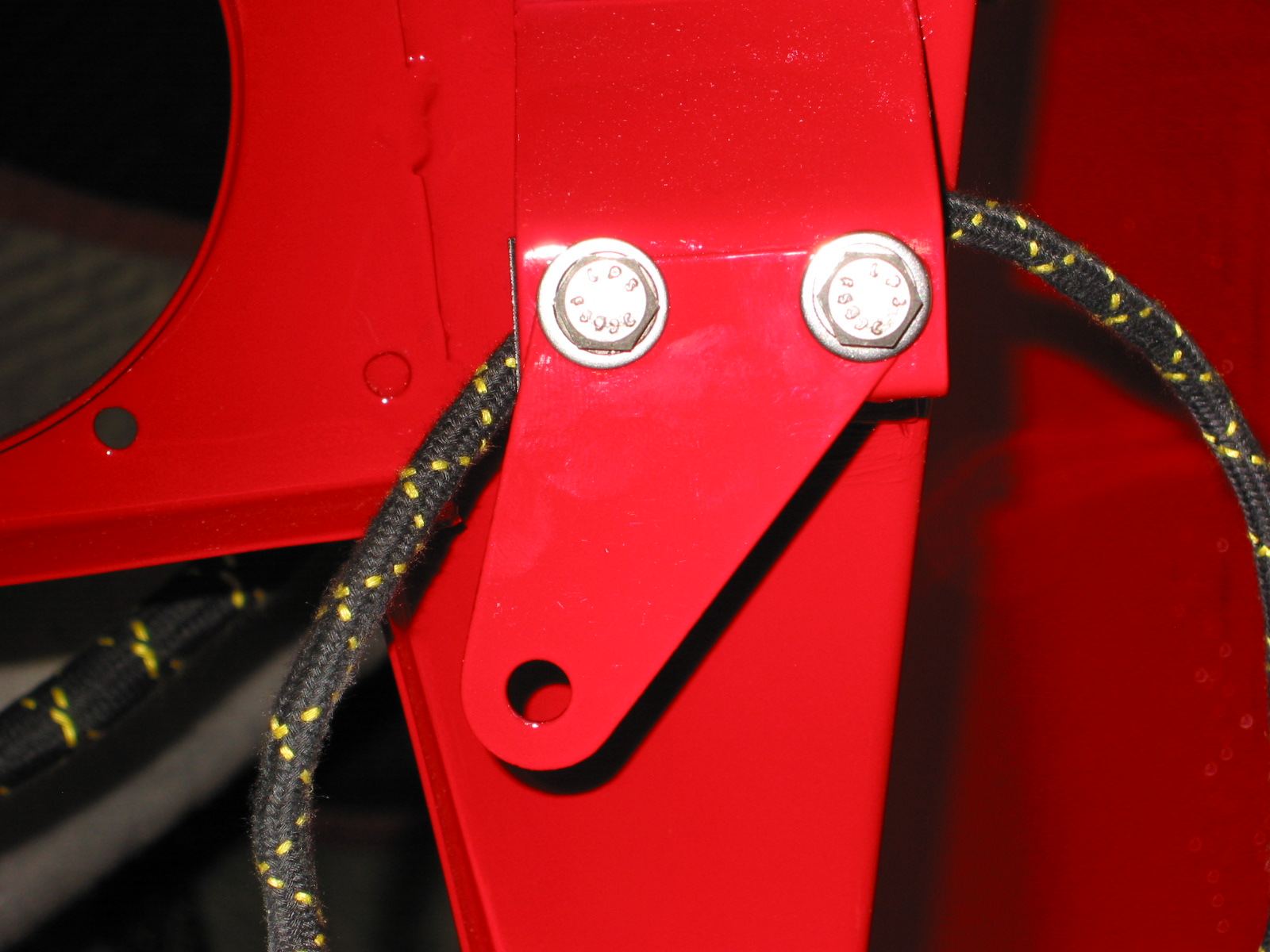
horn brackets red LH
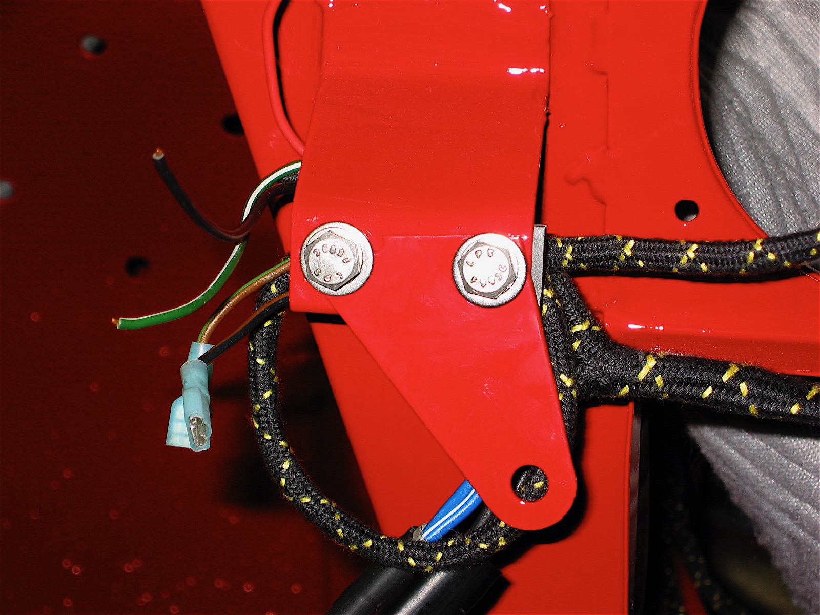
horn brackets red RH
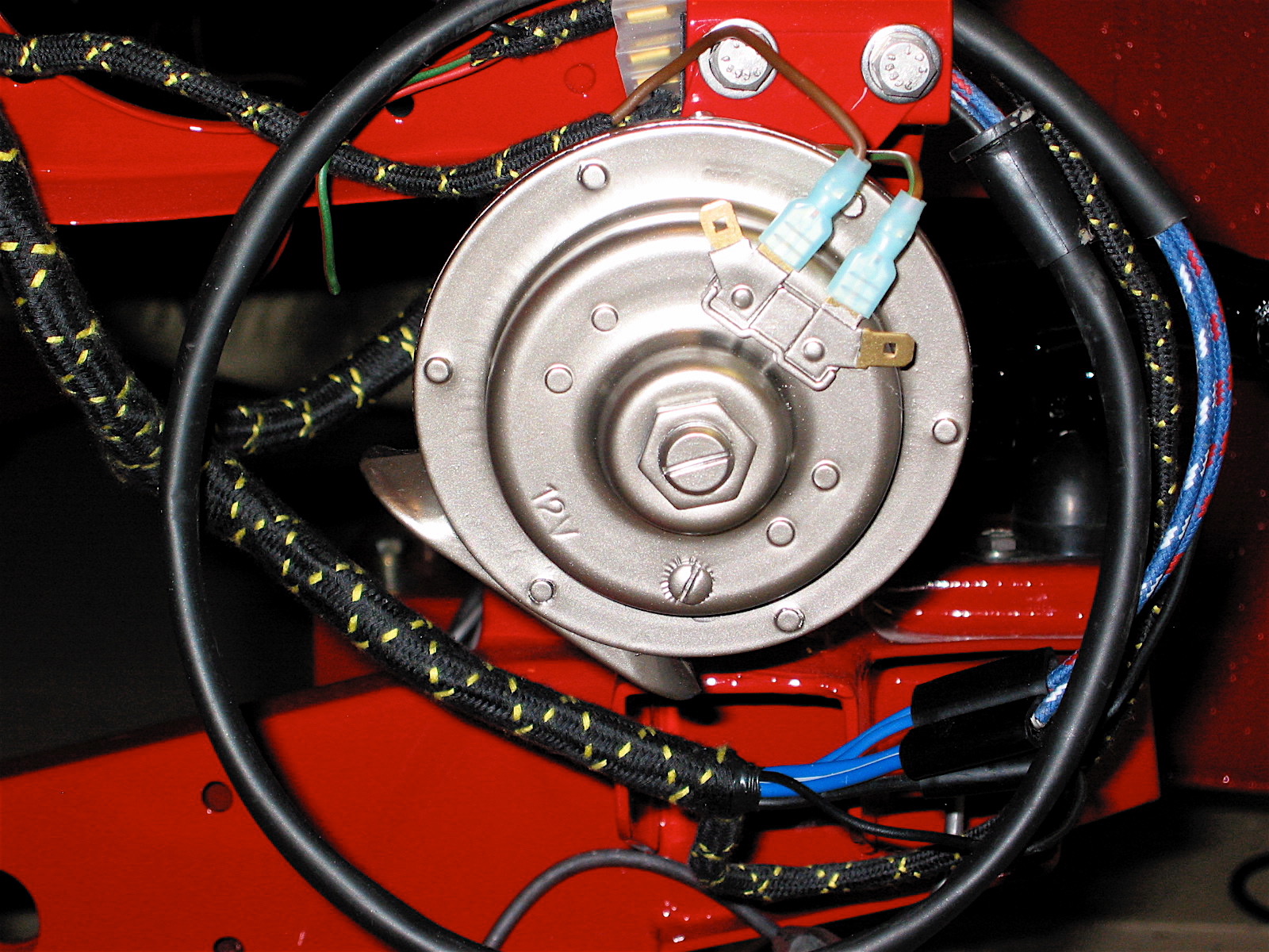
Horn painted
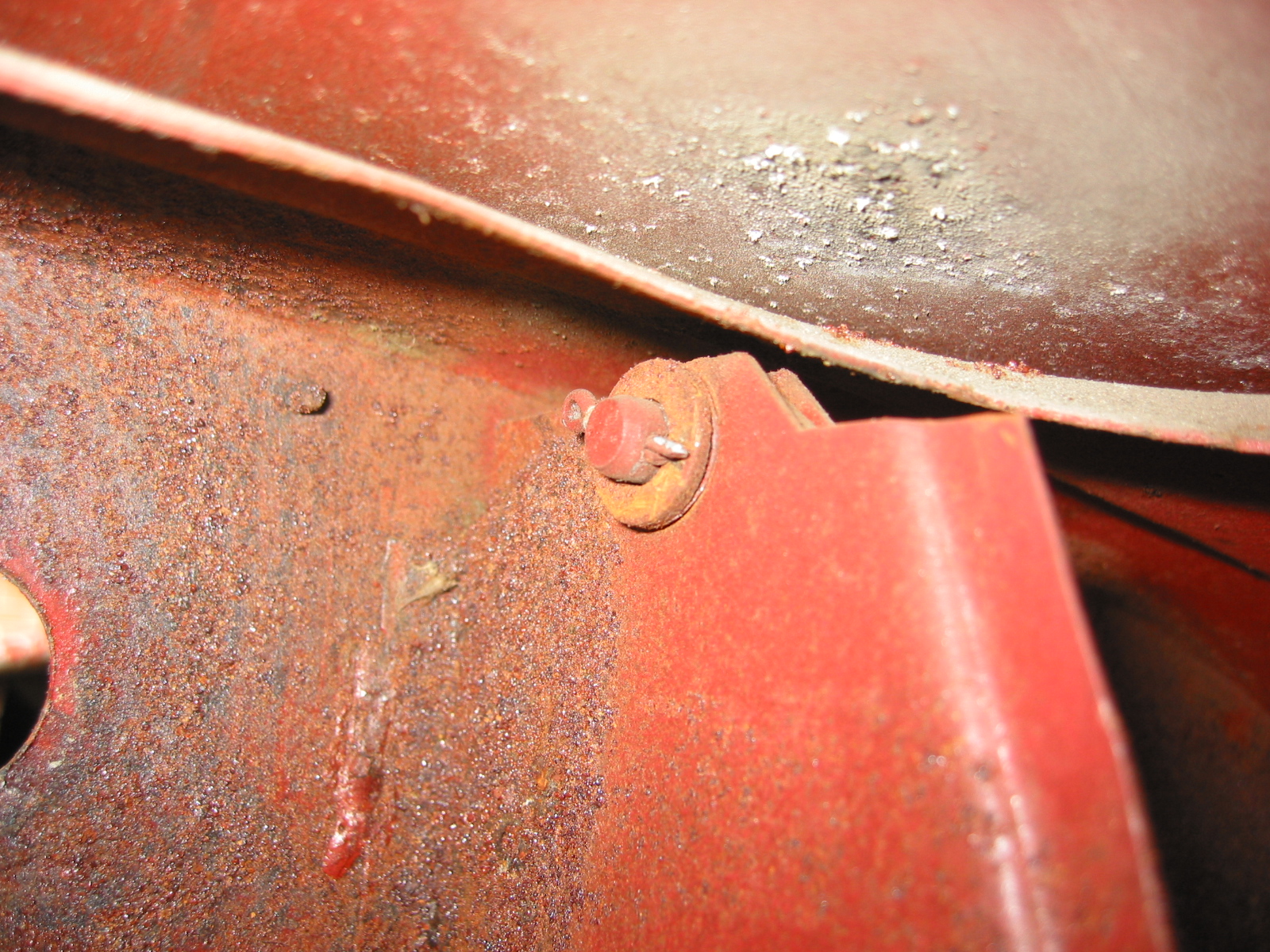
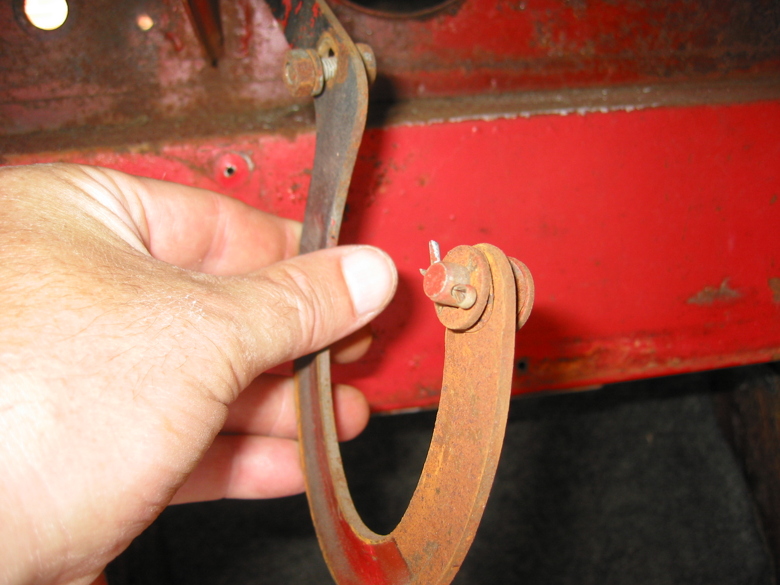
They used metric 7mm bolts. Then I installed the little bracket for the bonnet release, the remote control rod support bracket as well as the hydraulic fluid reservoir bracket.
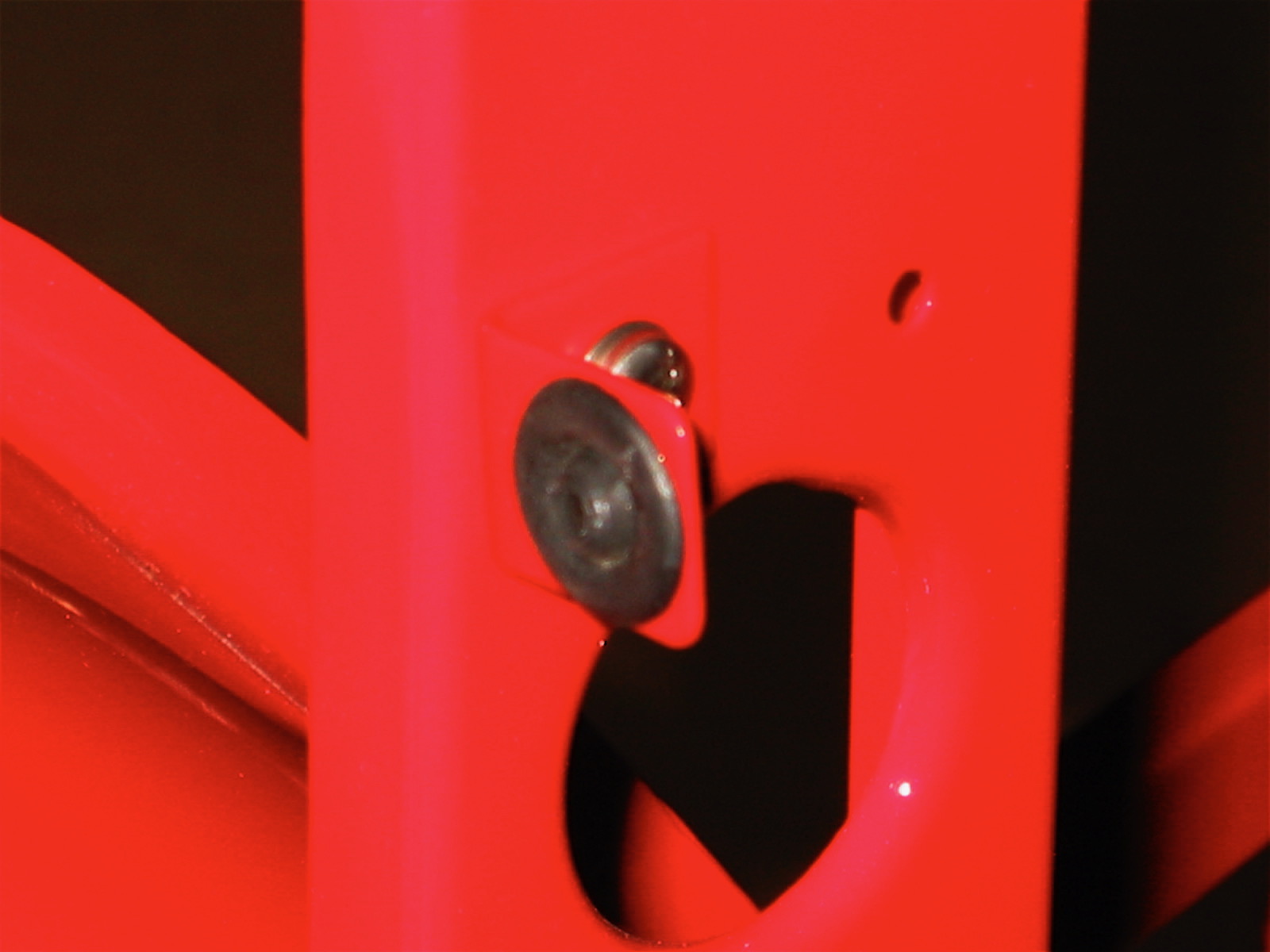
bonnet release rod bracket
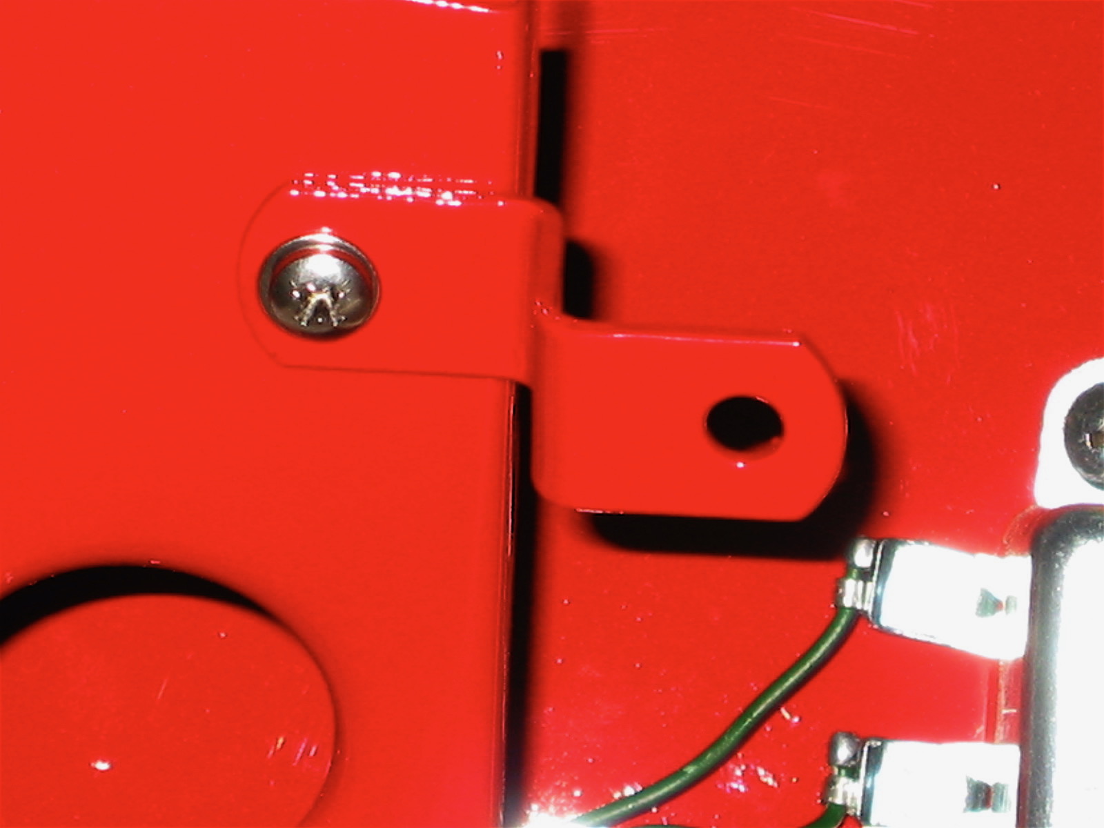
fluid reservoir bracket
The bonnet hinges were the next items to install. I greased the clevis pins and used stainless split pins.
Bonnet Hinge
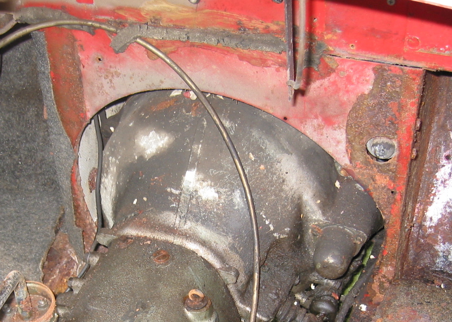
Two big items in my storage bins were the Smiths heater blower and the Cape International interior heater I will be using to upgrade the heating system in the car. The Cape unit, in addition to improved heating efficiency also has a two speed fan. More details are available in the Heating/Cooling section of the website. I went ahead and installed these two items just to make a dent in my storage container!
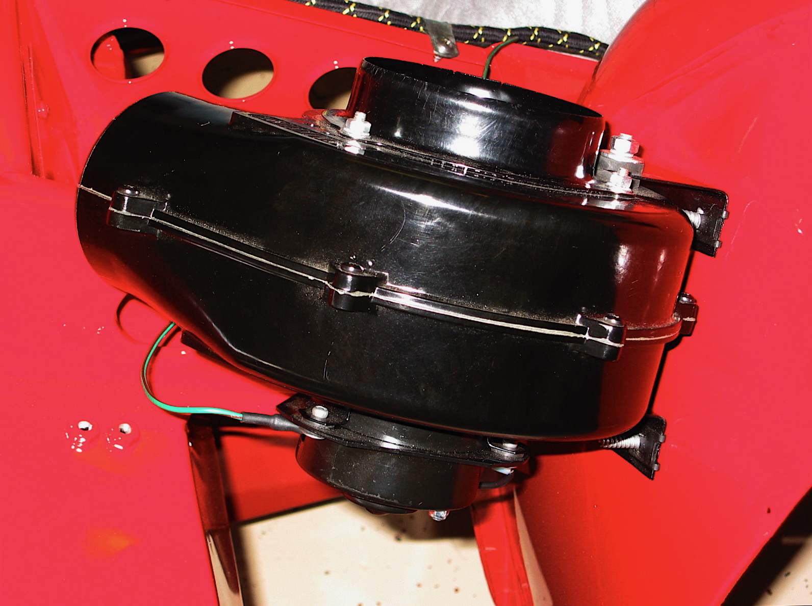
heater blower 1

Cape heater 2
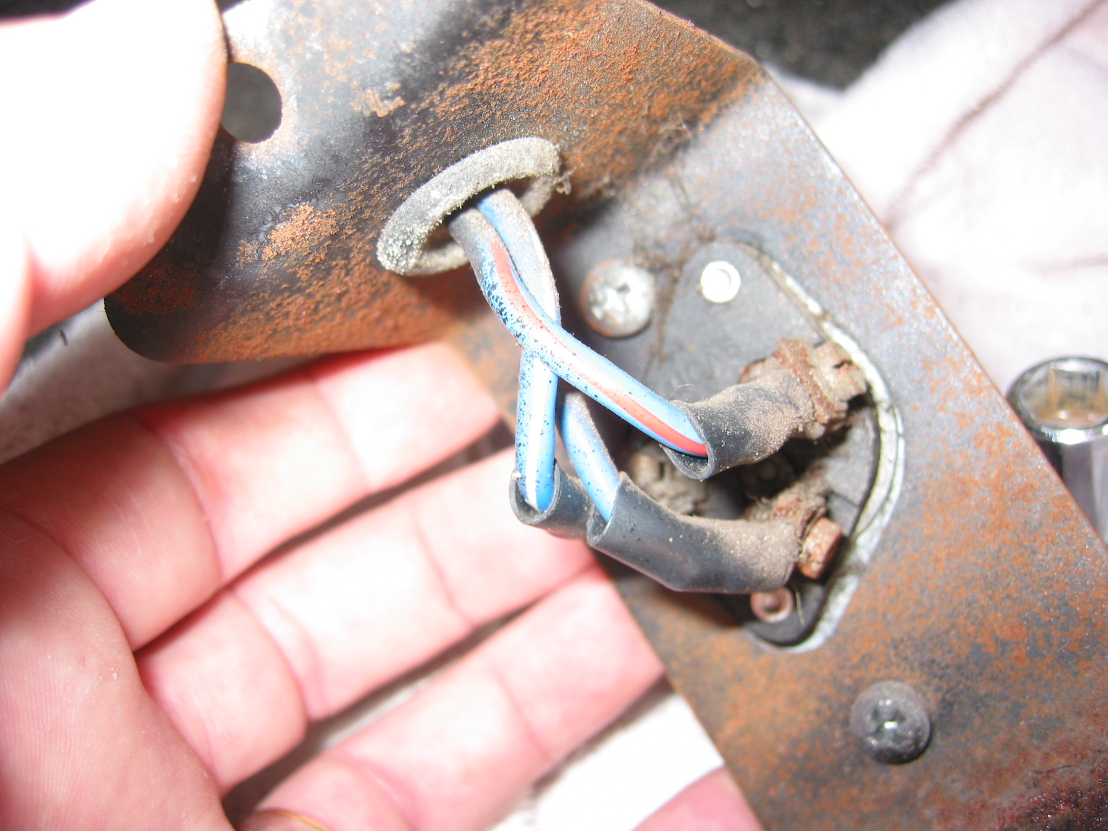
One thing I wanted to get done early in assembly before tiny spaces got crowded was the installation of the wiper motor assembly rubber grommets. These are a pain to get in, but a little liquid dish soap and muscle did the trick.
Wiper Motor grommets