In this entry I will identify some, but not all of the major electrical components in the MK2, that are not addressed in their own entry or post.
Electrical System Overview
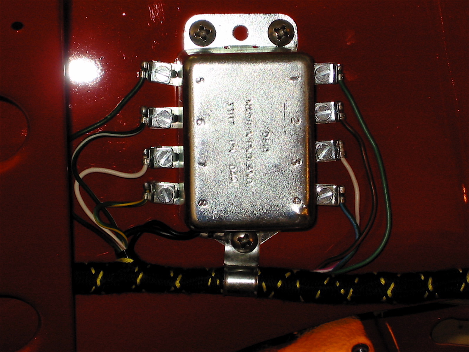
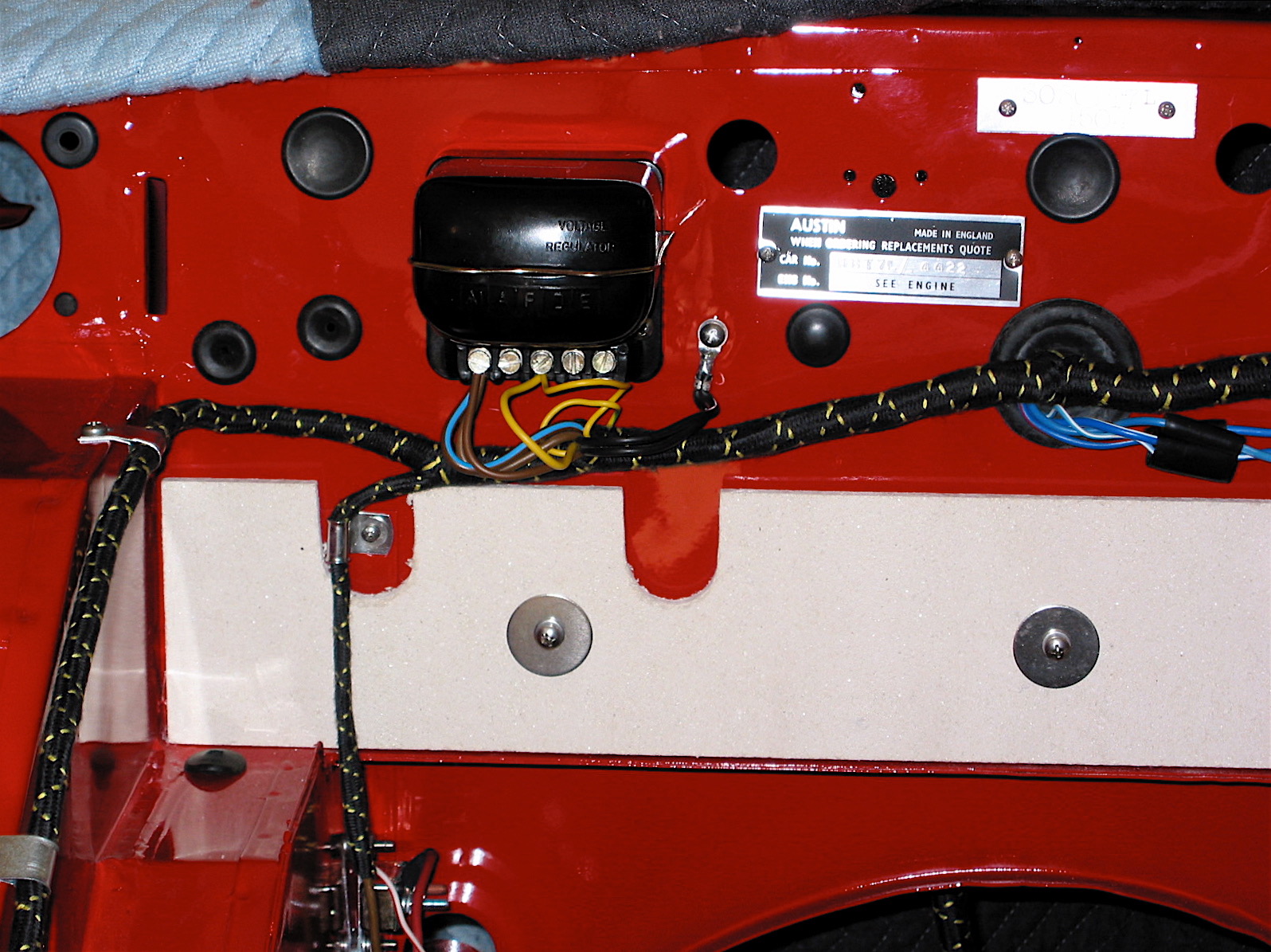
The Jaguar MK2 being British and a product of the mid-sixties has a positive earth electrical system. The starting system utilized a battery mounted under the bonnet, an ammeter, a starter solenoid on the firewall, a starter motor, a dynamo – commonly referred to as a generator in the U.S., a voltage control box or regulator along with a fuse box consisting of just two fuses, a Lucas ignition coil and a Lucas distributor with manually adjusted points.
My Mk2 has an updated electrical system. I have converted the system to negative ground an have installed a significantly upgraded fuse box and complementary wiring harness.
Alternator
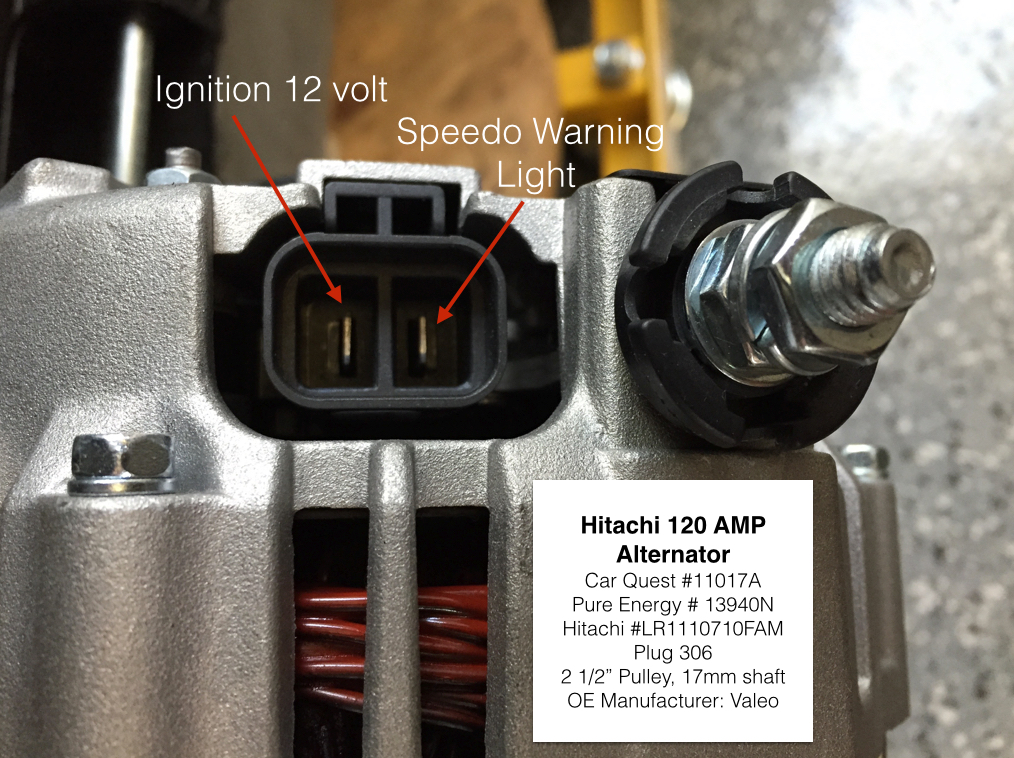
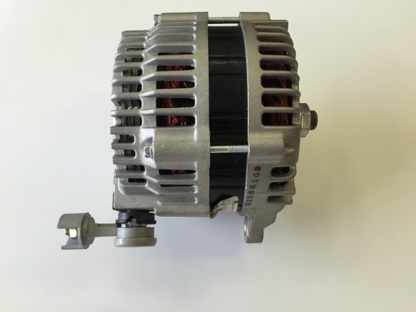
I am installing an alternator in lieu of the original dynamo/generator. The alternator I am using is an Hitachi manufactured by Valeo for the 2004-2008 Nissan Maxima. It produces 120 amps. Detail information:
Hitachi 120 AMP Alternator
- Car Quest #11017A
- Pure Energy # 13940N
- Hitachi #LR1110710FAM
- Plug 306
- 2 1/2” Pulley, 17mm shaft
- OE Manufacturer: Valeo
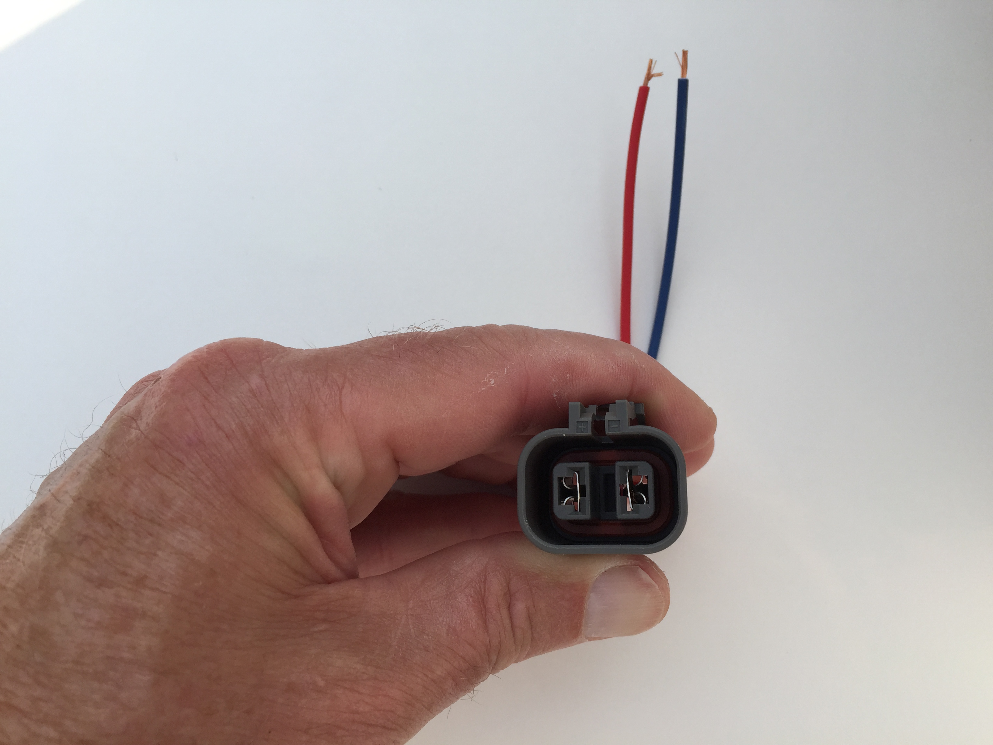
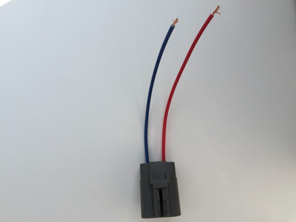
I ordered the Connector plug or “pigtail,” from National Quick Start Sales: http://store.alternatorparts.com/partnoc1900.aspx
Part # C1900 Hitachi, Mando, and Mitsubishi Alternator Wiring Repair Plug, Female. Alternator Wiring Harness Repair Connector with 2 Female Terminals
B#: 180
Y: 2
X: C
Z: 010

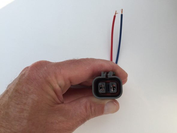
C1900 Hitachi Alternator Female Wiring Repair Plug
C1900 Hitachi Alternator Female Wiring Repair Plug
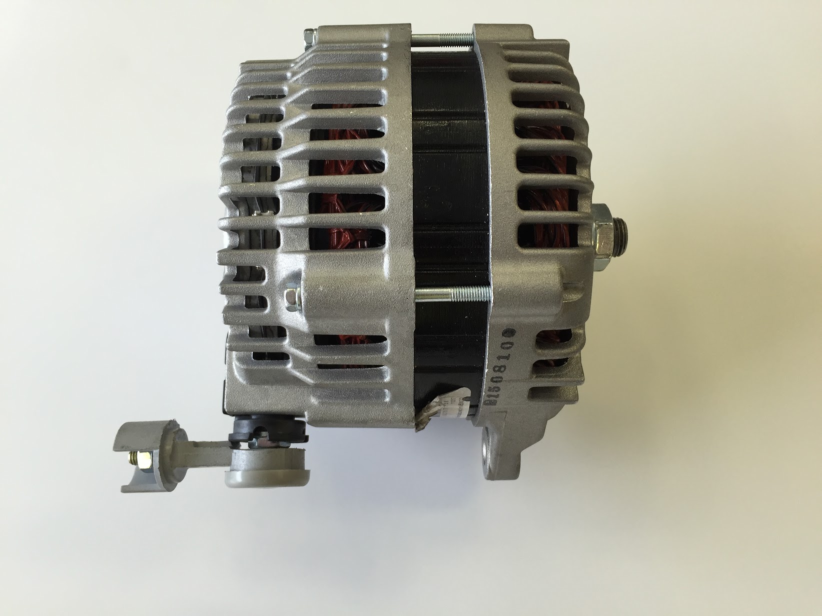
The alternator was supplied with a serpentine pulley. Because I am air conditioning the Jag, and the compressor uses a “V” belt, I switched out the pulley for a “V” pulley with a 17 mm shaft. I had to have a machinist turn the pulley on a lathe to cut away some material to end up with a good fit.
Being Japanese, the mounts for the alternator are obviously metric – and of different sizes! 18mm on rear bolt and 15mm on the front bolt with a 5/8″ wrench on both nuts.
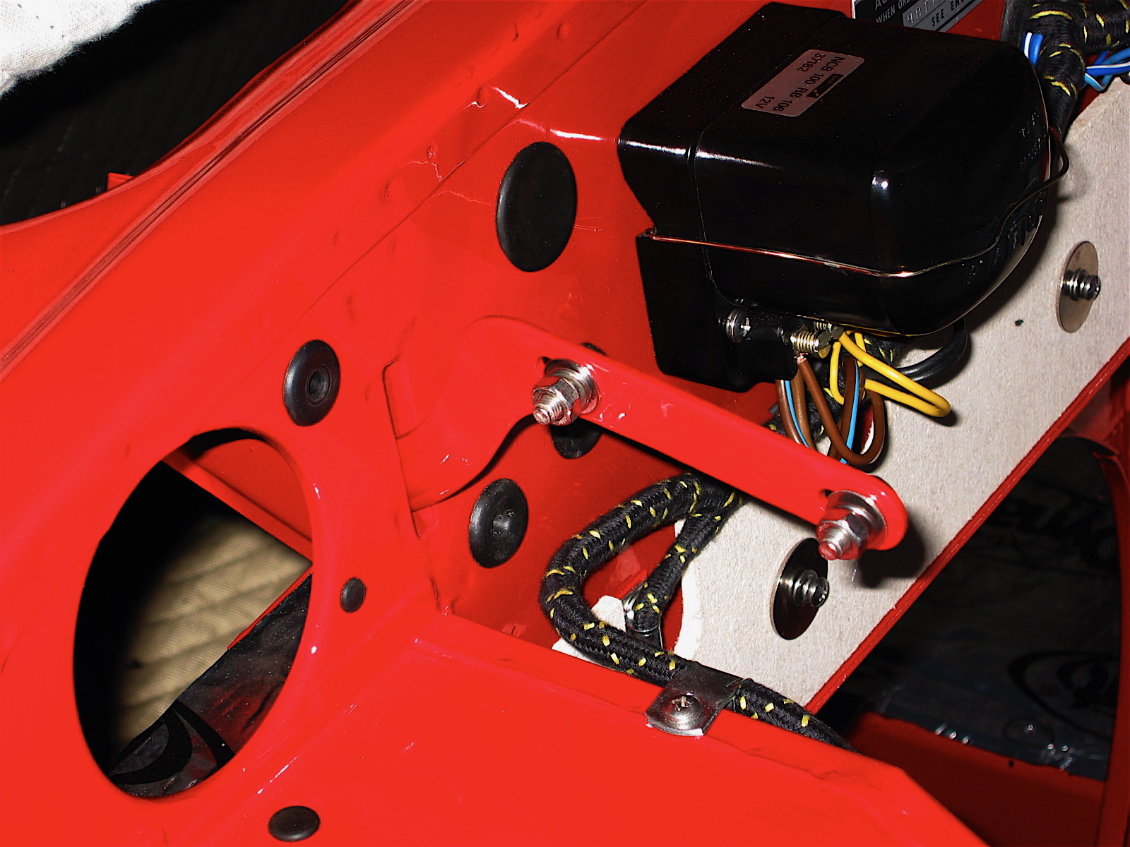
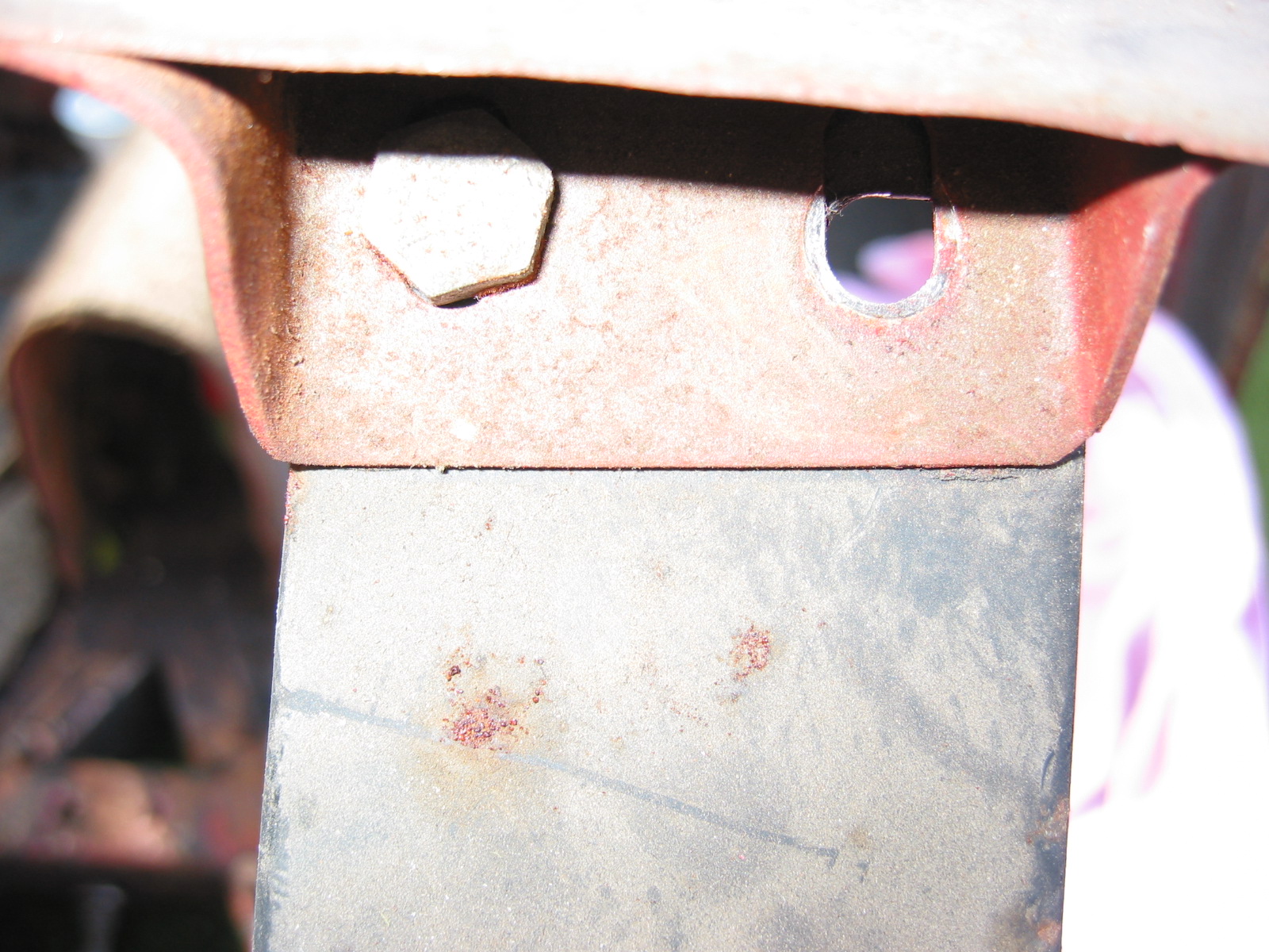
The power input post for the Hitachi alternator is, unfortunately for me, on the top of the alternator when it is mounted to the motor. In this position, the top of the post is only about 1/4″ from the bottom of the steal air conditioner compressor mounting bracket. This can be seen in the image below:
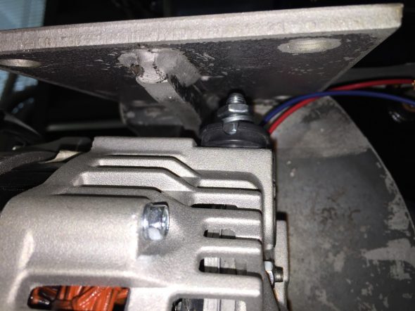
Alternator Power Post
Obviously, this is not a good situation. Bill Rader, owner of Blue Sky Radiator and Electrical came to my rescue! He was able to place an adapter on the alternator that redirected to power post to the rear of the alternator thereby eliminating my problem.
Redirected Power Post on Alternator
Battery
To be determined.
Distributor
I had such good fortune with the Dutch “123” electronic distributor in my Big Healey, that I chose to use the same product in the MK2. The Jag does use a different model, number “Jag 6-R-V.” The unit offers 16 different advance-curves, that can be selected via a little switch. Information on the Forums suggests that the #1 or #2 advance curve may be the best to use with the 3.8 Jag motor with total advance of no more than 34 degrees. In our test runs of the engine we did NOT connect the vacuum line to the distributor. I will need to do additional research before settling in on a particular setting.
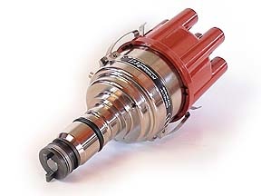
123 Electronic Distributor
| SPECIFICATIONS |
| direct. |
: CCW (topview) |
| voltage |
: 4,0-15,0 Volts |
| range |
: 500 – 7000 rpm |
| temperature |
: -30 to 85 Celsius |
| coil |
: stock or High Energy coil |
| |
primary coil NOT below 1,0 ohm |
| dwell |
: constant current, fully autom. |
| time-out |
: after 1 second current is switched off |
| spark-bal. |
: better than 0,5 degr. crankshaft |
| vacuum |
: advance starts at 5 inchHg |
| |
stops at 10 degr. @ 10 inchHg |
| |
gearshift retard > 17 inchHg |
| max.advance |
: 45 degr. crankshaft |
| wiring |
: red = +6V or +12V, black = ‘-‘ coil
|
Installation instructions are available here:
123 JAG6 Distributor Installation Instructions
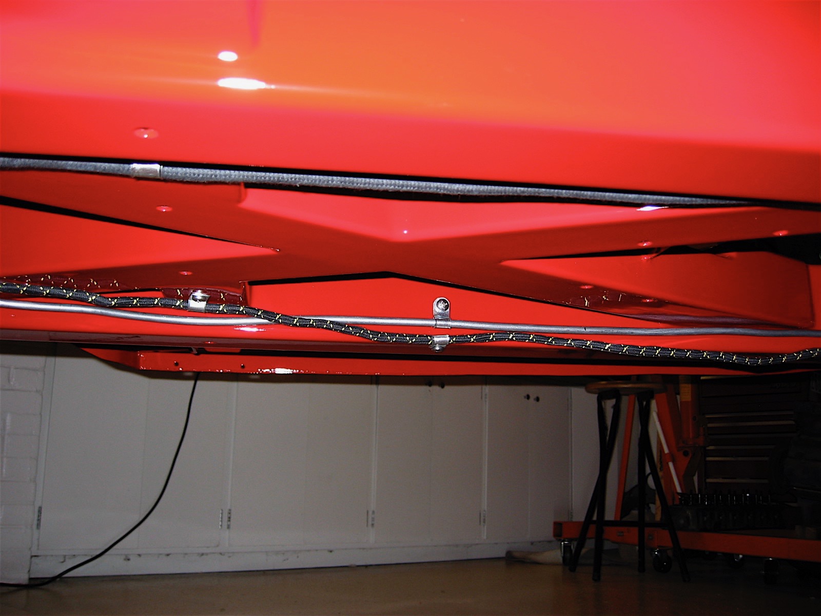
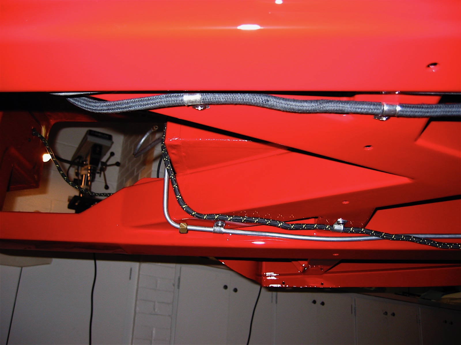
There is considerable debate in the Jaguar community about the the vacuum advance for the 123 distributor if used on the 3.8 engine. Some say to not connect the vacuum advance, others say to use the ported vacuum advance port on the carburetor, but my friend Mike Gassman, from Gassman Automotive has suggested that performance will be safely enhanced by using direct manifold vacuum. This article written by a retired General Motors engineer corroborates Mike’s thinking. Ported Vacuum vs Manifold Vacuum.
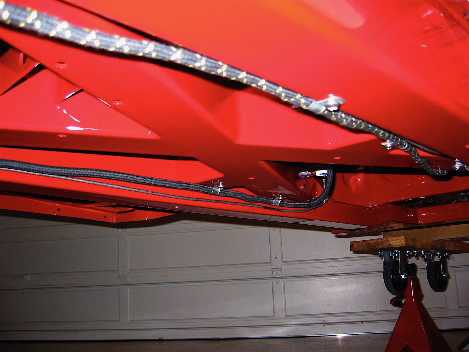
I am going to try the manifold vacuum for my project and see how the engine performs. I have decided to split the vacuum hose that connects the manifold and the brake reserve tank with a “T” connector. The smaller connection is then routed to the vacuum port on the 123 distributor. If you choose to do this, DO SO AT YOUR OWN RISK! Manufacturers would recommend against doing anything that might compromise braking vacuum but in my opinion, and that of others, the reserve tank provides more than ample vacuum pressure for the braking system.
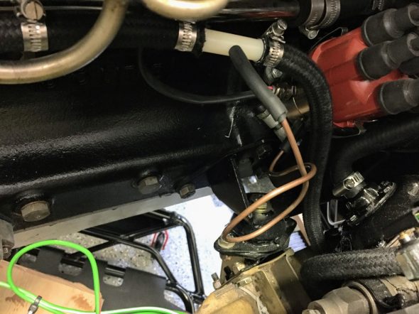
Vacuum Line to Distributor
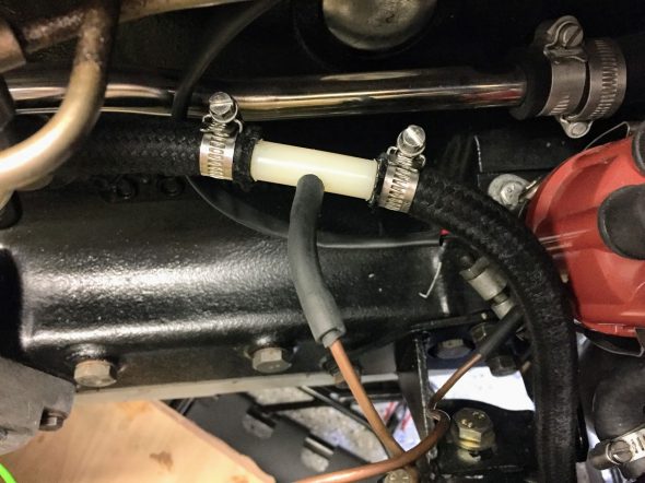
Vacuum Line to Distributor
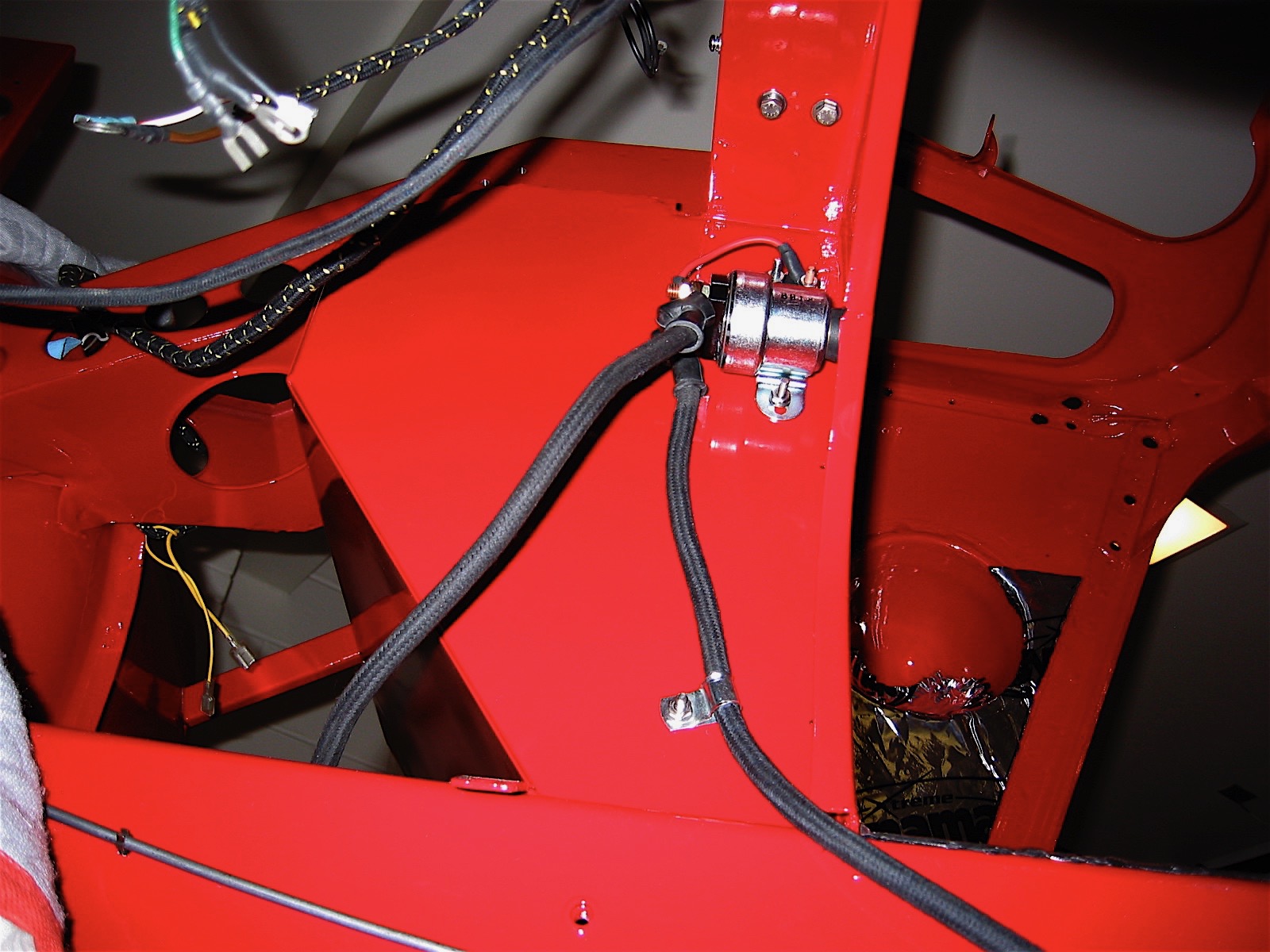
Ignition Coil
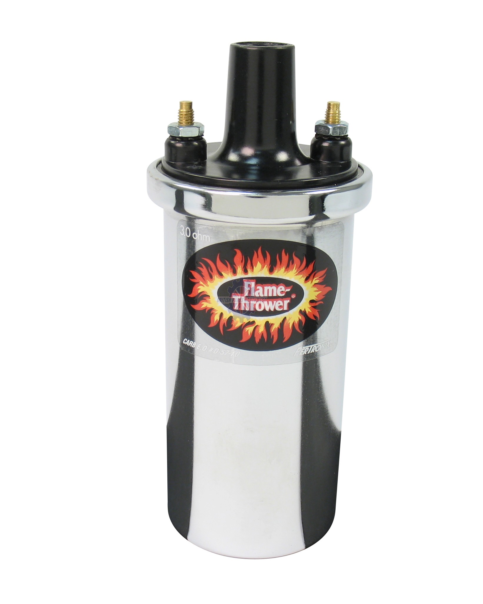
The original Lucas coil was replaced with a “Flame Thrower” high output, 3.0 ohm, 40,000 volt, internally resisted unit made by Pertronix, model number 40501. The coil has such a prominent place on the engine that I wanted it to look nice with the polished cam covers. Consequently, I opted to go with the chrome case for the “bling” effect, but it is also available in black.

Pertronix Ignition Coil 40501
Ignition – Spark Plug Wiring
I elected to purchase a ridiculously expensive assembled wiring conduit kit for Pertronix ignition from XKs Unlimited using 7mm black wire. The spark plug and coil ends are pre-installed.
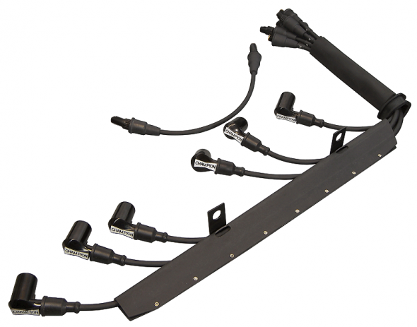
Spark Plug High Tension Wiring with Conduit
Spark Plugs
I am using NGK BPR5ES plugs with a 0.045 gap as recommended by Paul Salt on the Saloon-Lovers Jag Forum for solid wires with no resistors. BP5ES otherwise.
Starter
“High Torque” or “Gear Reduction” starters are available for the MK2 3.8. These starters are considerably smaller and lighter than the original Lucas starter, but more importantly they have considerably more cranking power. The starter can be set up to either use or eliminate the original starter solenoid and I decided to keep the original set-up. I sourced the new starter from SNG Barratt.
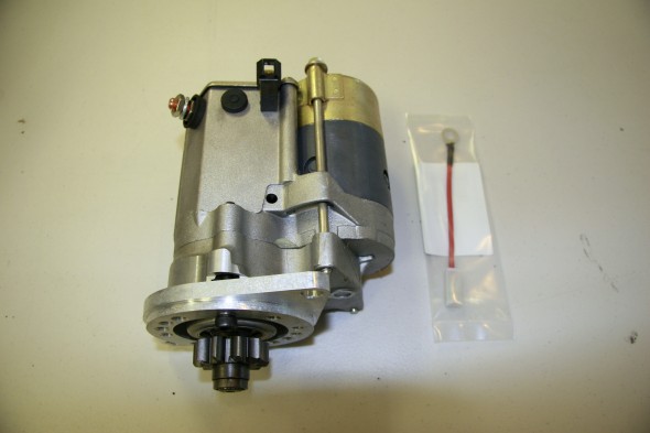
SNG Barratt High Torque Starter
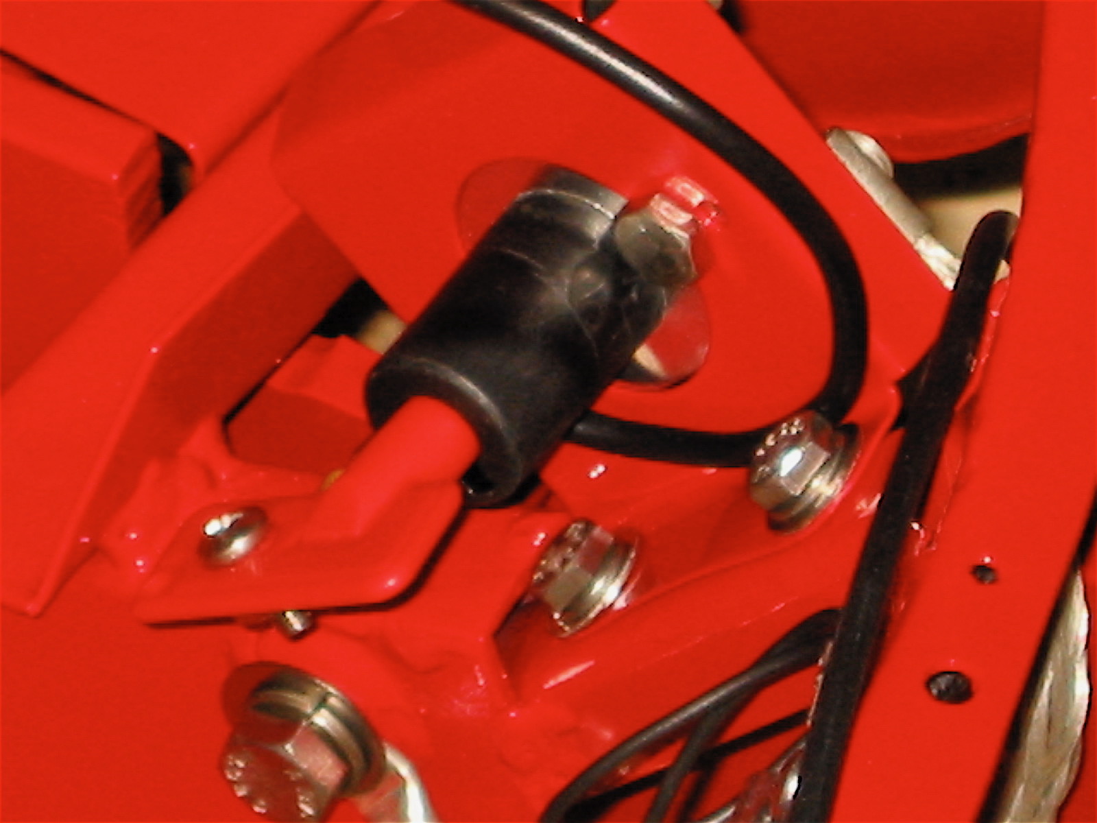
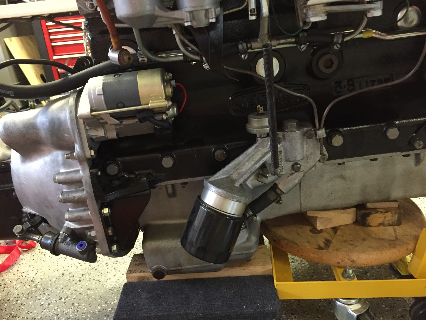
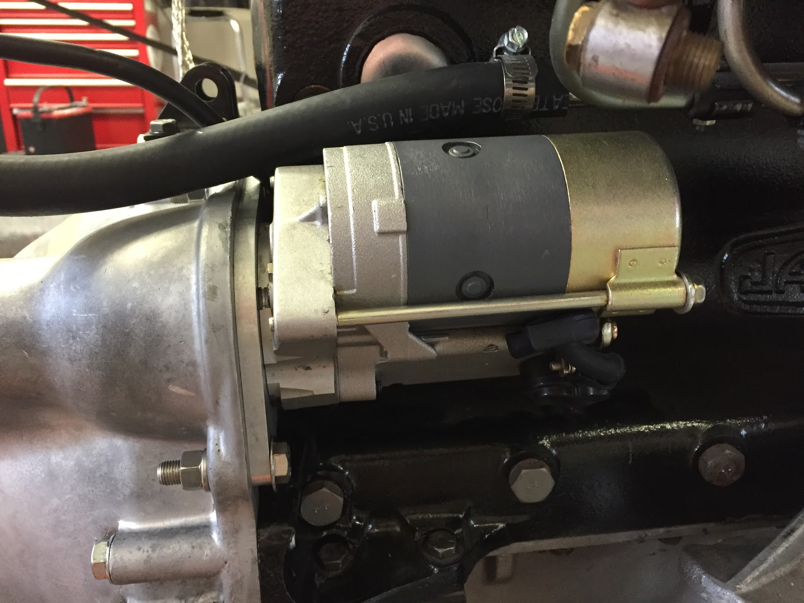
The starter is located on the right side of the engine and is secured to the bell housing with two 3/8″-24 x 1/12″ hex head bolts, flat washers and split washers. I am using the original starter solenoid on the firewall so it is necessary to connect the short jumper wire to the + terminal of the starter upon installation. Since it is a bit crowded once the starter is mounted I attached the cable from the starter to the starter solenoid before installation of the starter. A rubber boot was used to cover the terminal. It will be connected to the firewall starter solenoid after the engine is mounted in the car.
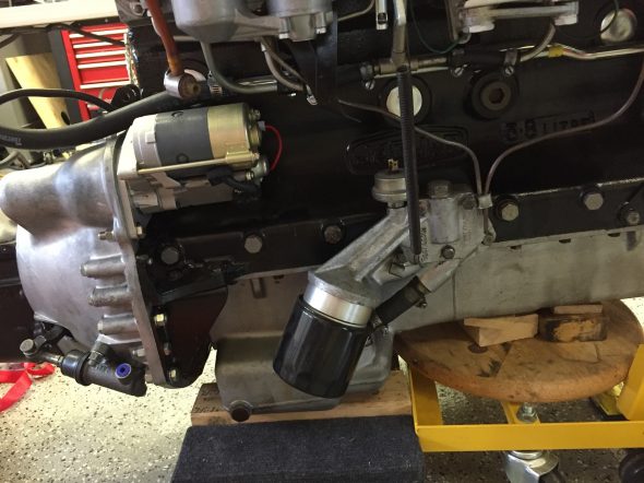
Starter Installed on Engine

Starter Installed on Engine – Close-up
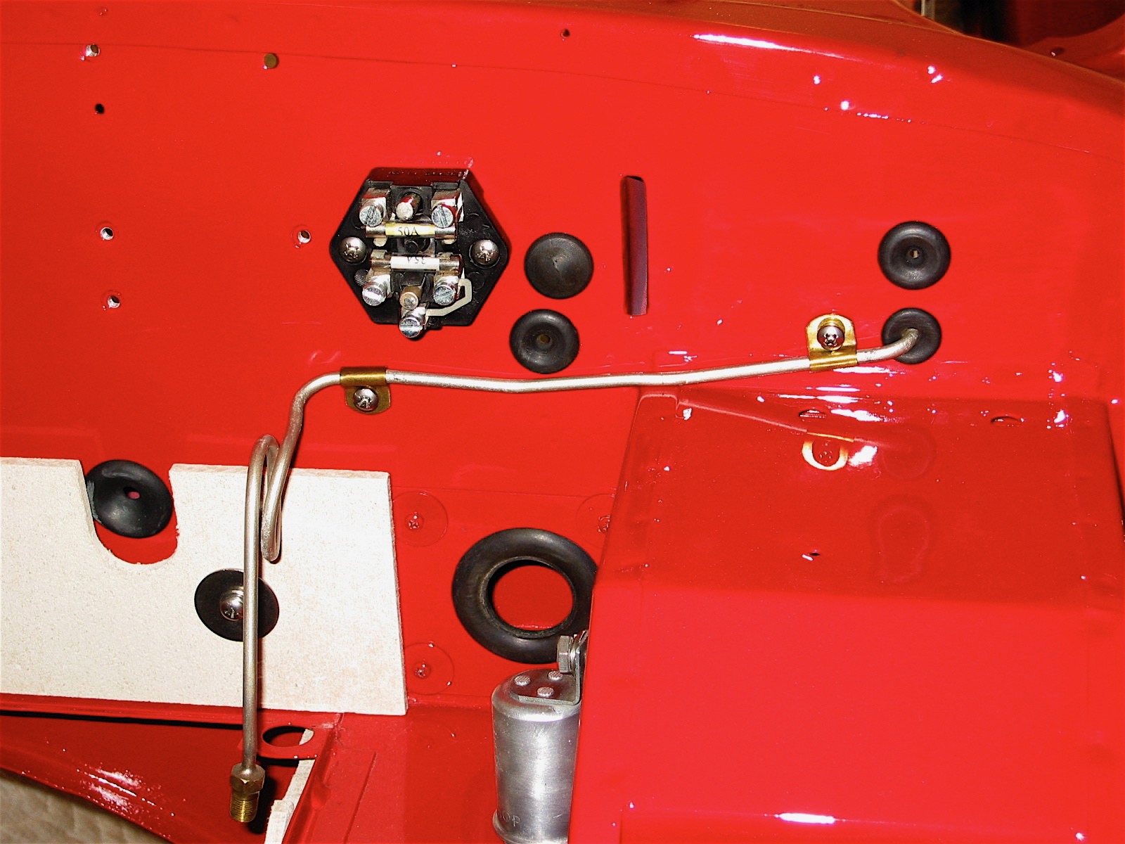
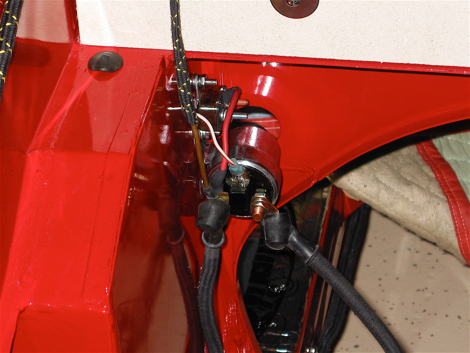
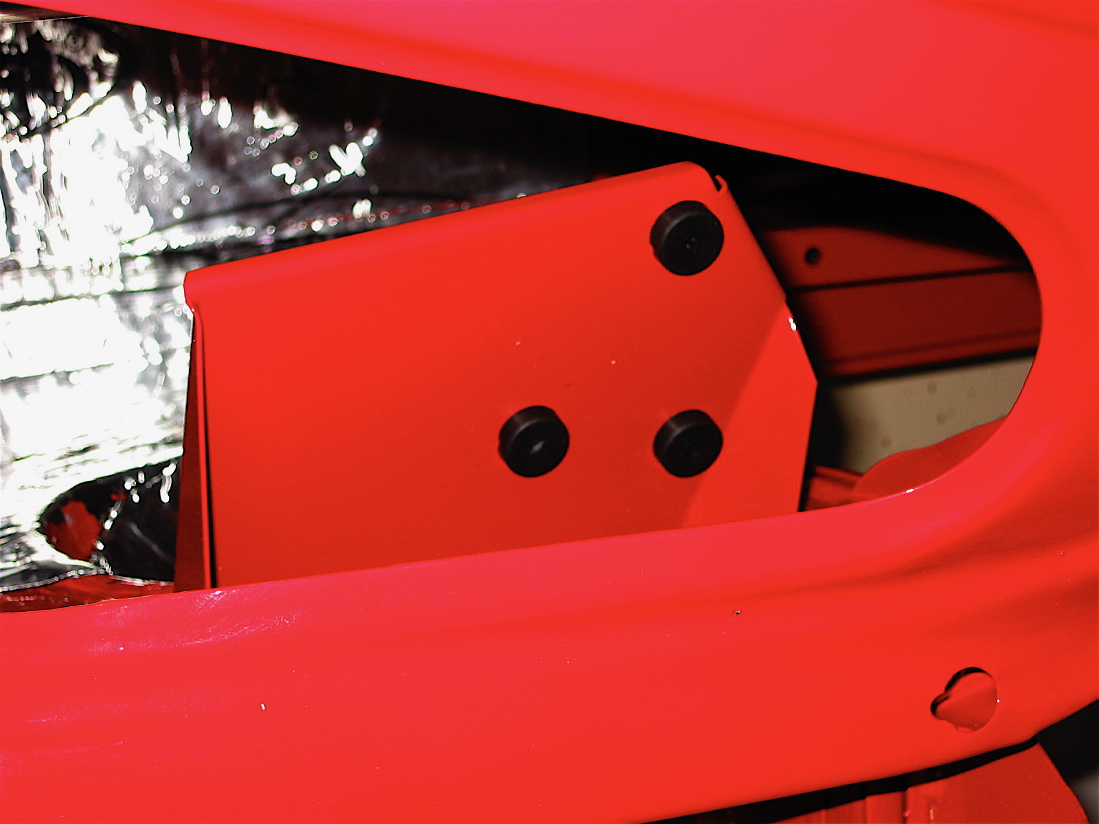
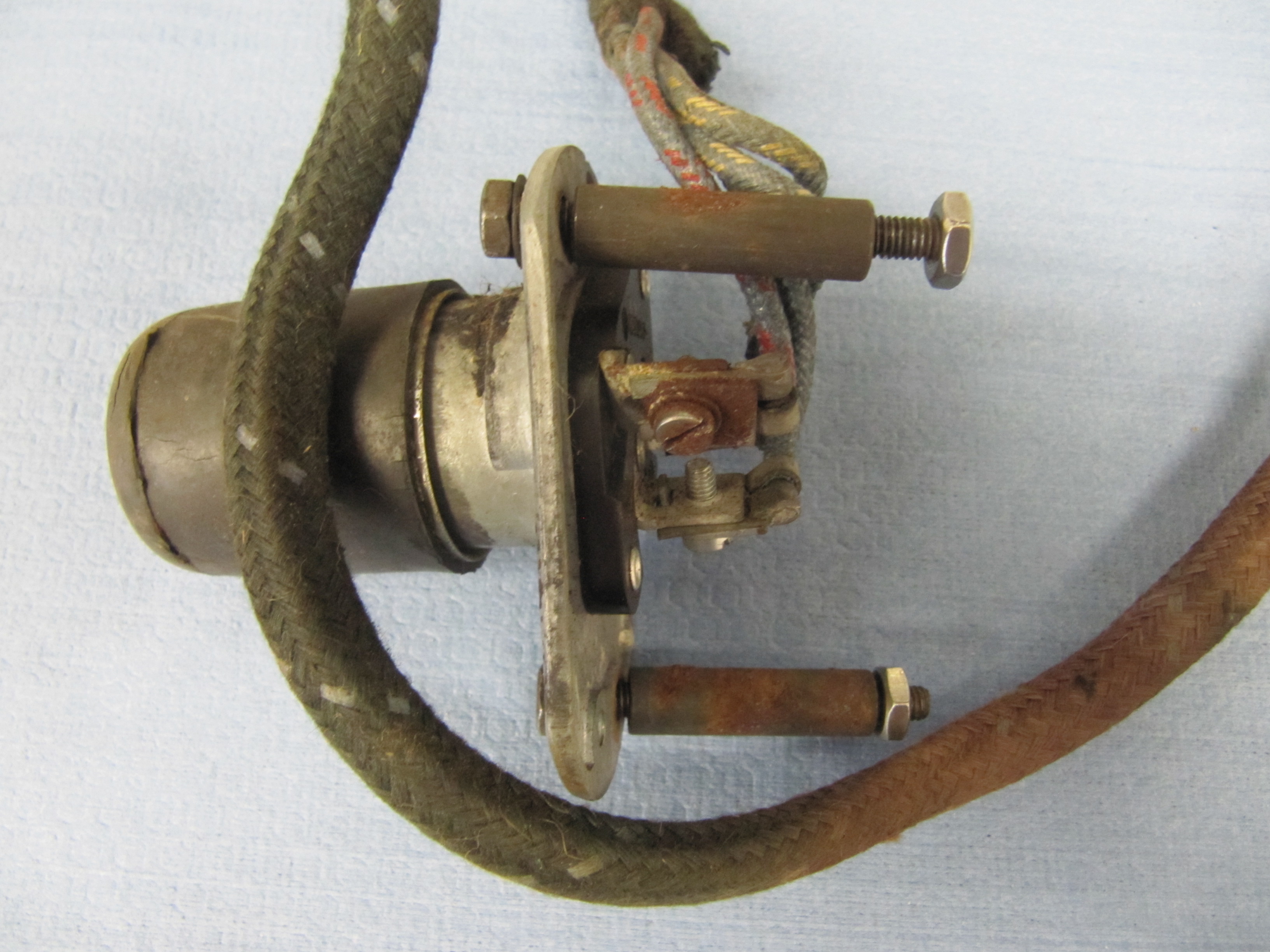
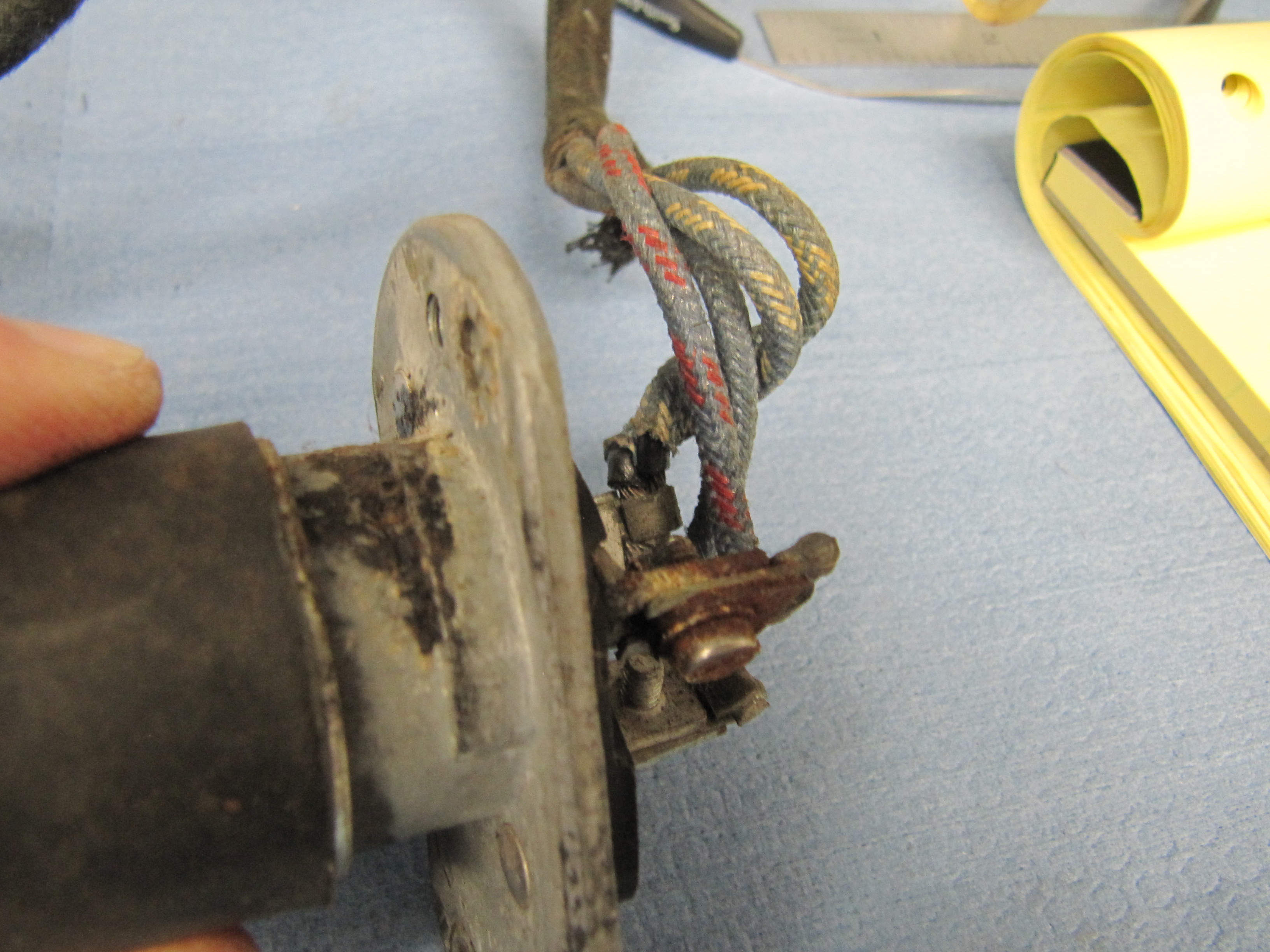
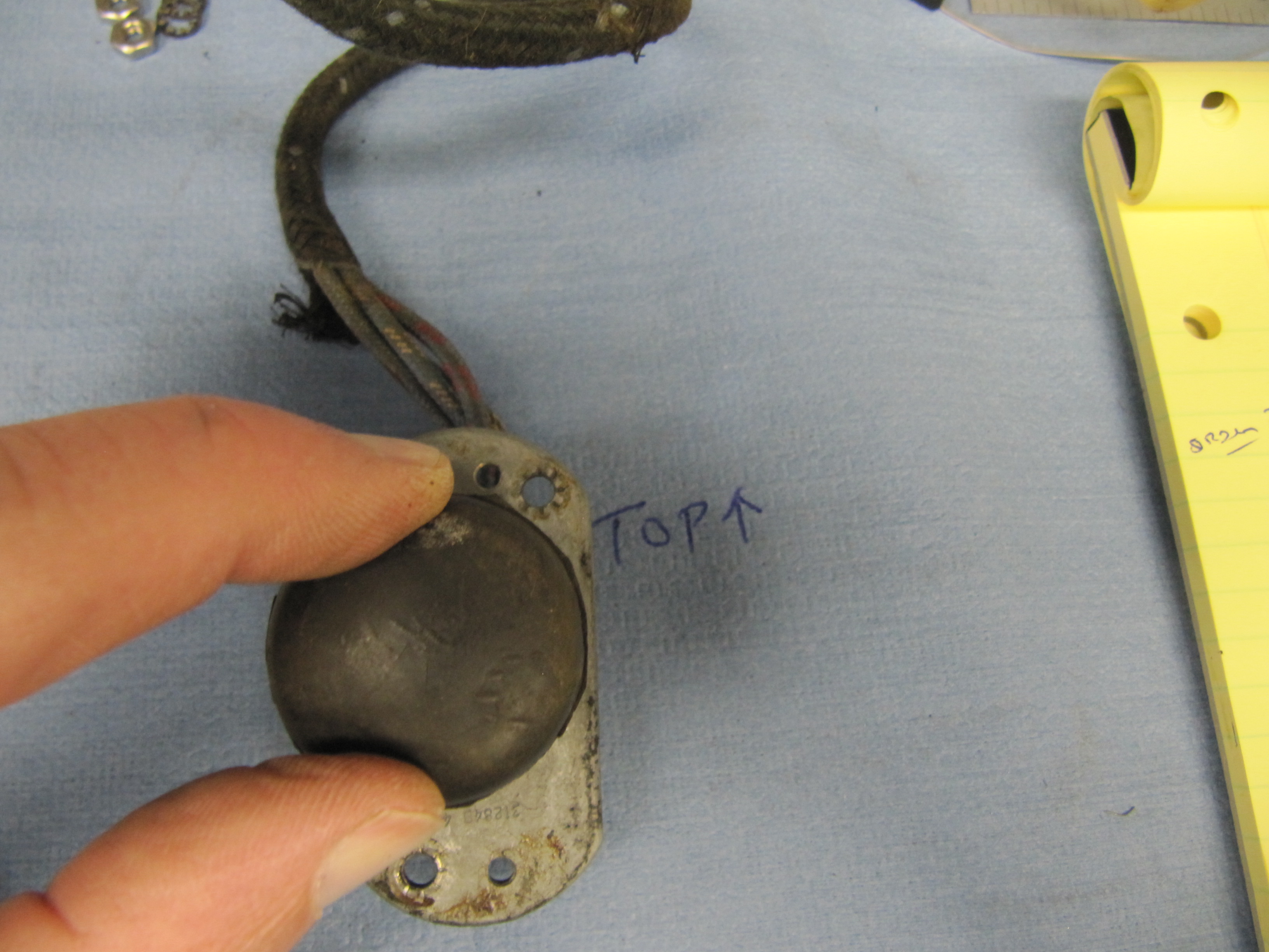
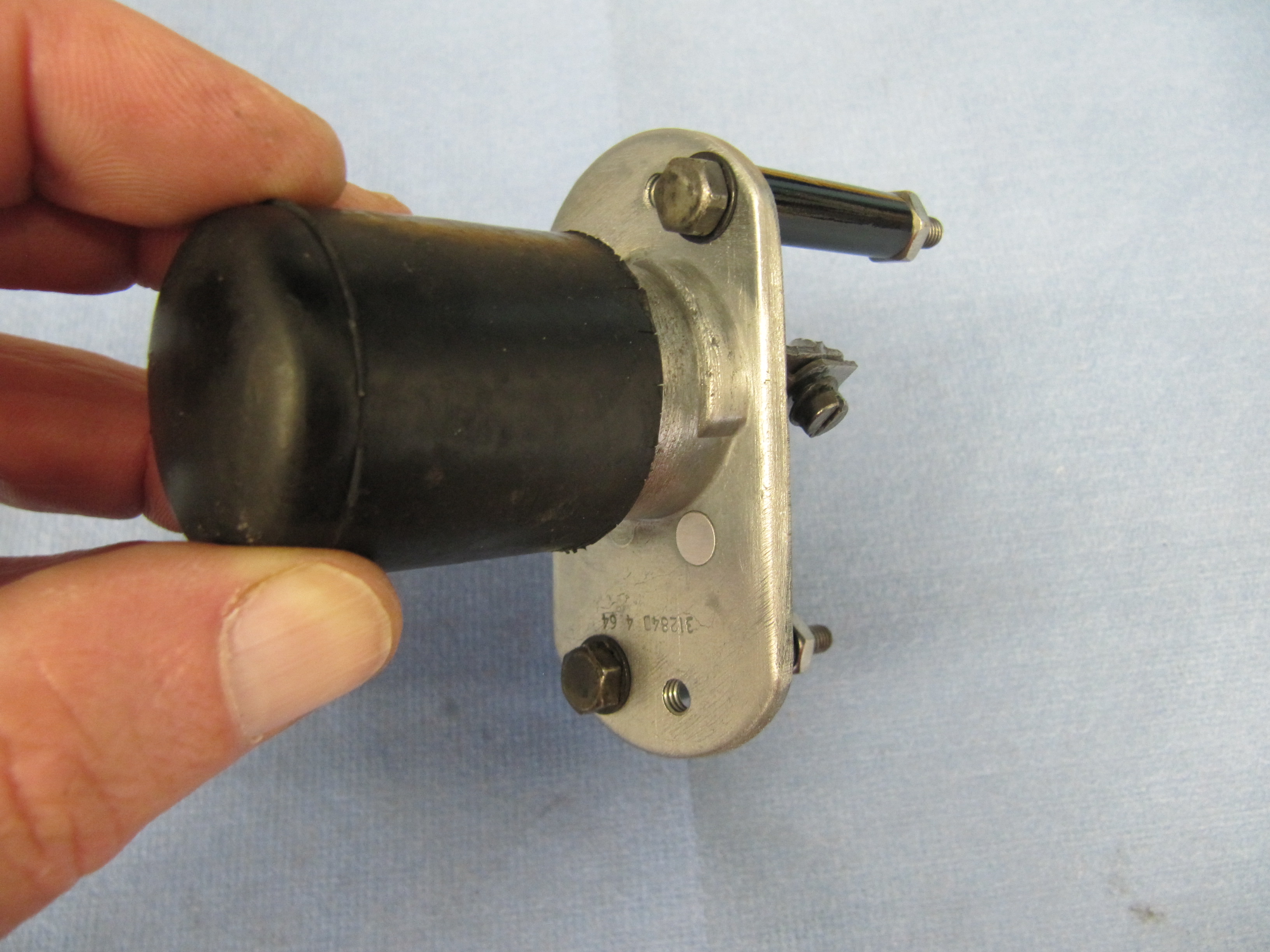
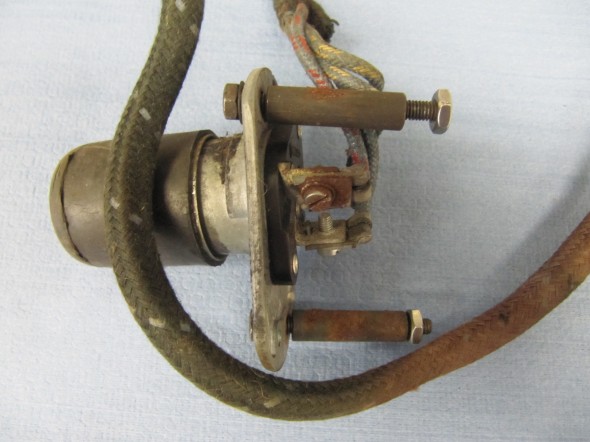
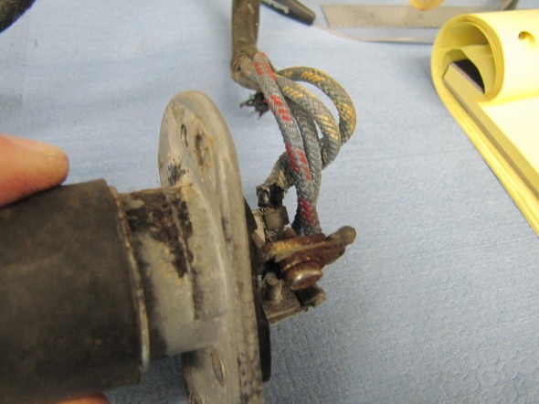
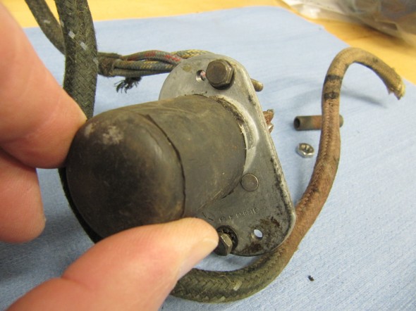
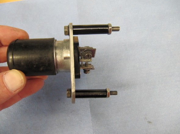
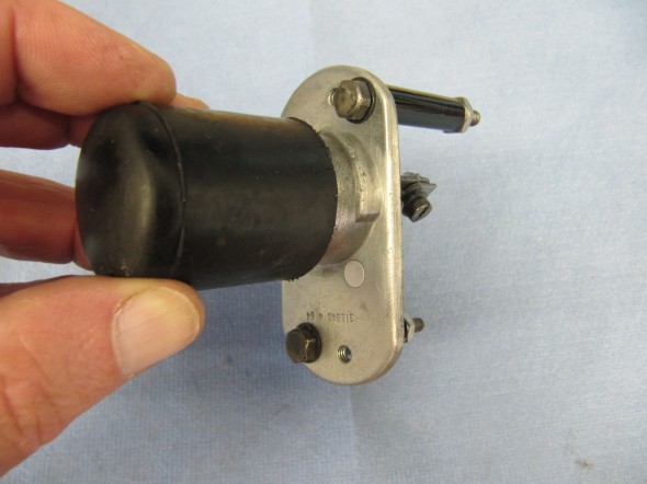
Starter Solenoid
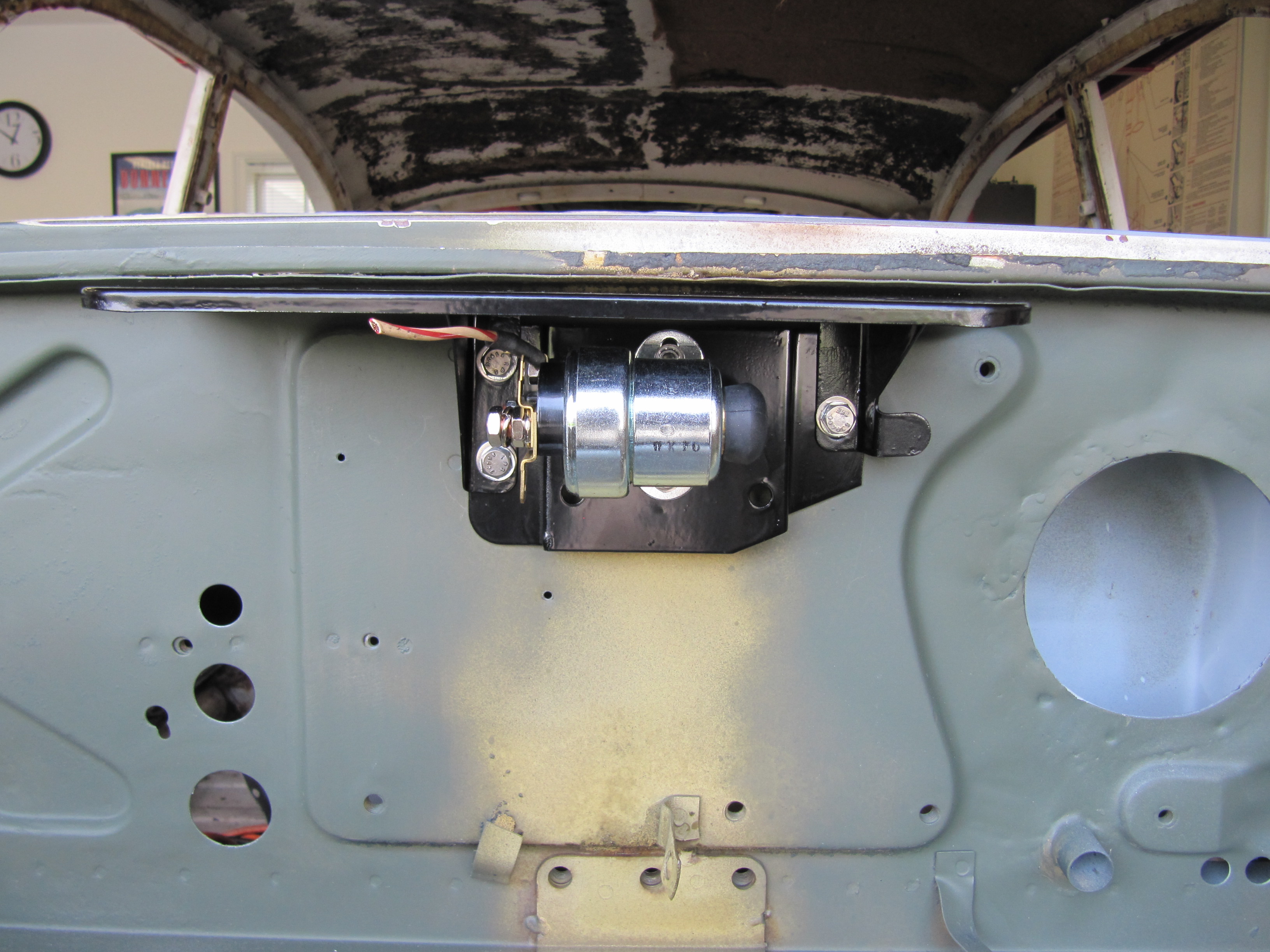
I am using a new reproduction solenoid. This is an image of a trial fitting of the solenoid on the Weather Protection Flange on the firewall.

Adaptor Plate Assembly for Solenoid and Solenoid Weather Protection Flange
Upgraded Brake Switch
I had planned to replace the MK2’s original hydraulic brake switch that activates the rear brake lights when the brakes are applied. The hydraulic switches currently available seem to experience a higher than normal failure rate. I encountered this same issue with my Austin-Healey 3000. In the Healey I replaced the hydraulic switch with a plug in the 4-way adaptor and installed a mechanical switch at the brake pedal. The wiring is the same as for the electrical switch. The mechanical switch was sourced from Watson’s Streetworks.
While I purchased the Watson’s switch to use in the MK2, I also found that Ron Francis Wiring sells an updated low pressure hydraulic switch that looks and mounts like the original. I decided to give this switch a try.
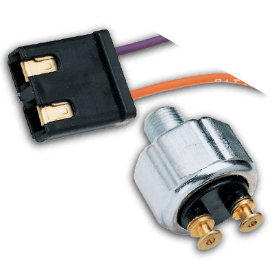
Ron Francis Hydraulic Brake Switch SW-32
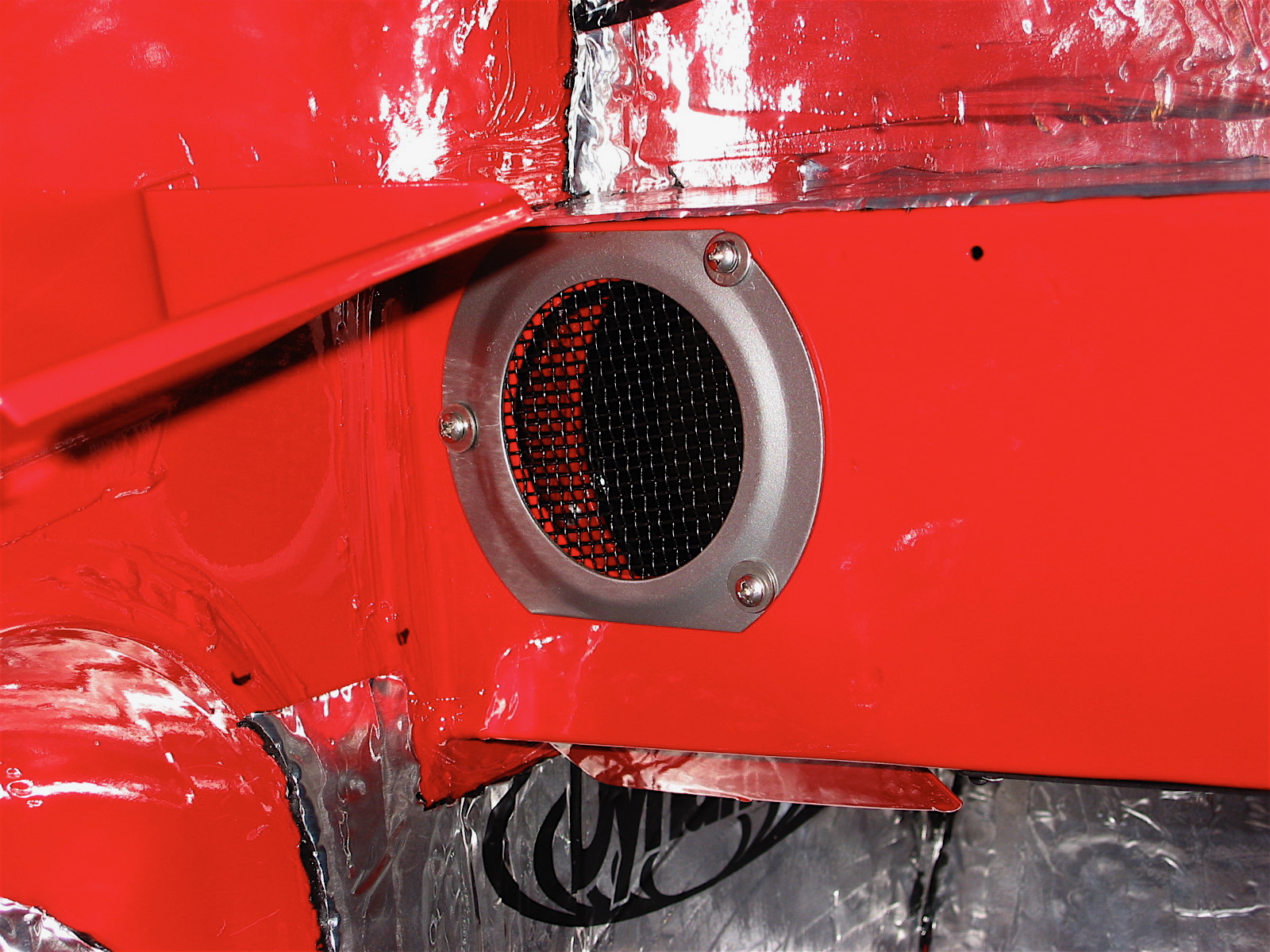
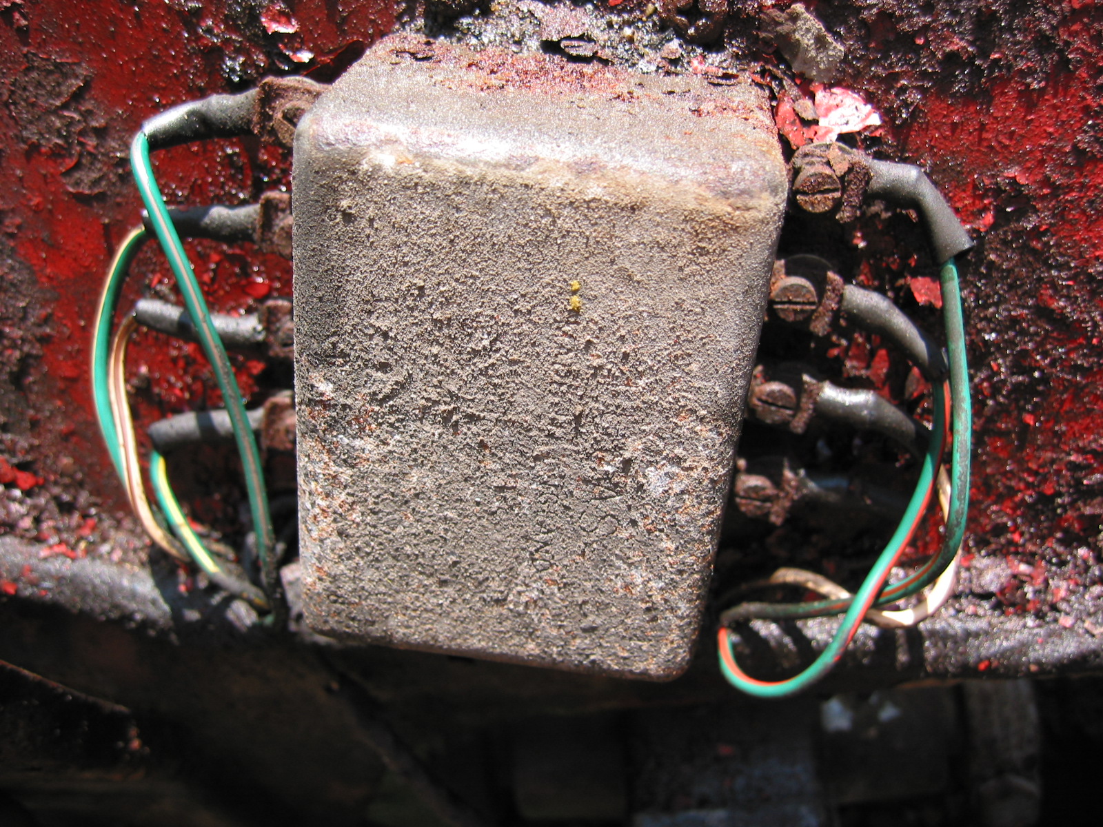
Horns
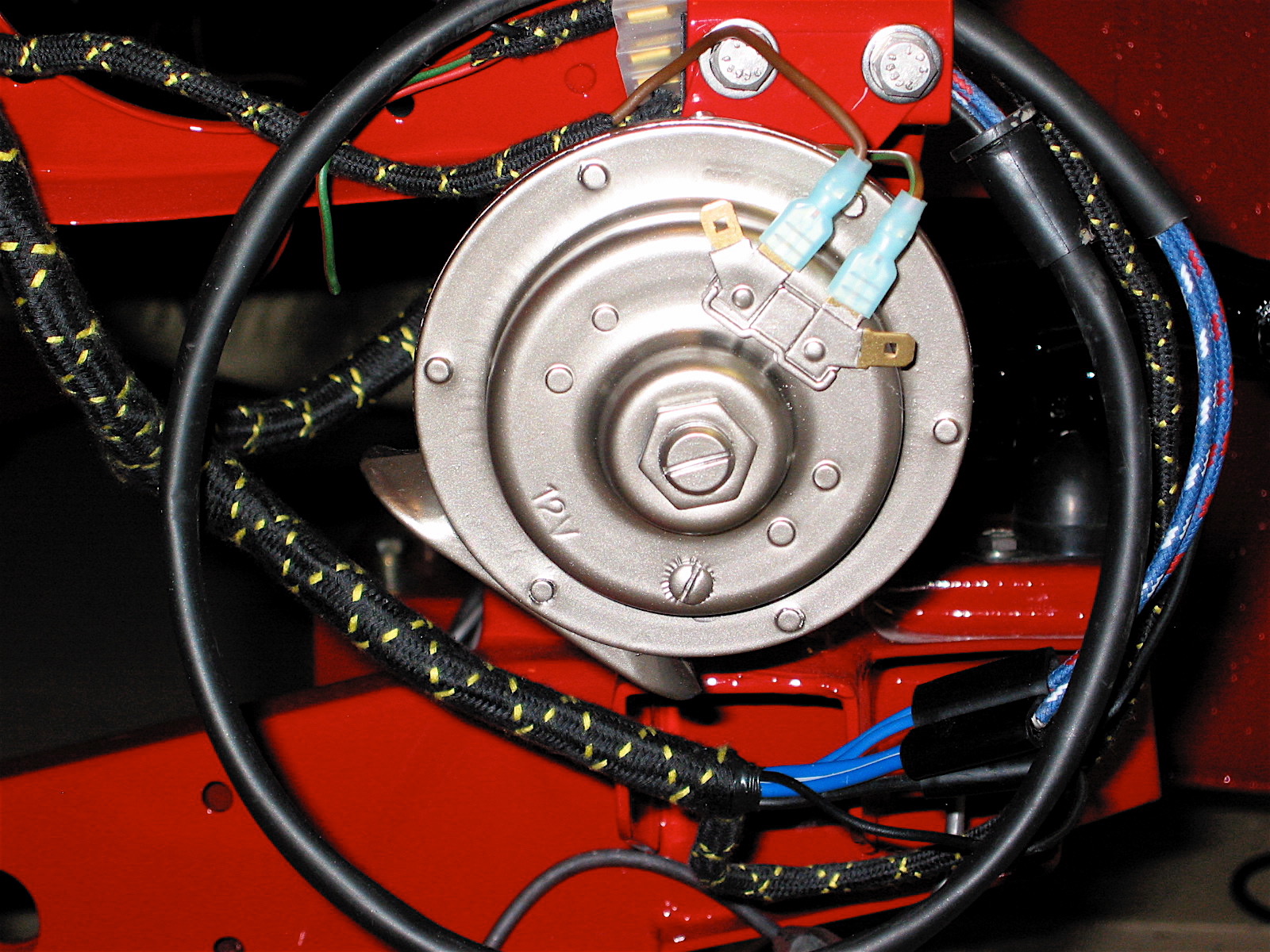
The horns are located at the front of the car and on either side of the engine compartment immediately below the radiator. My 1964 MK2 was equipped with horn model number WT (Wind Tone) 618U. I media blasted the two horns after stuffing the Flute with paper to avoid getting sand in the workings. I then took the domed covers off the high and low tone horns and painted each horn with POR-15 and overcoated with their spray Blackcoat product. I then sent the horns to E. Lawrie Rhoades, 7 Knollwood Rd, Medfield, MA 02052-2703 to have the electrical mechanism cleaned and tuned. Lawrie is a recognized expert on horn and wiper motor repair.
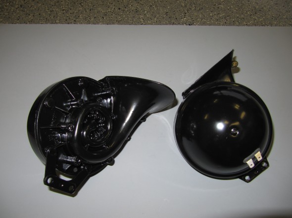
Horn Assemblies
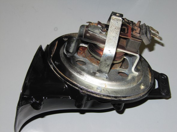
Horn Internals
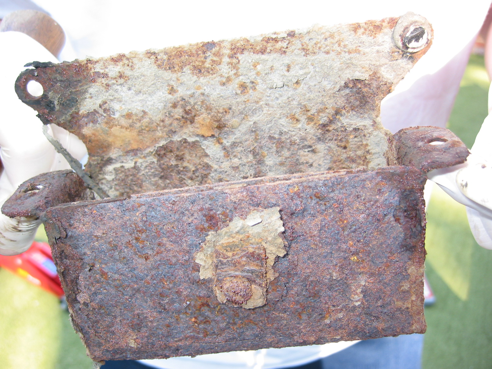
Horn Mounting Brackets
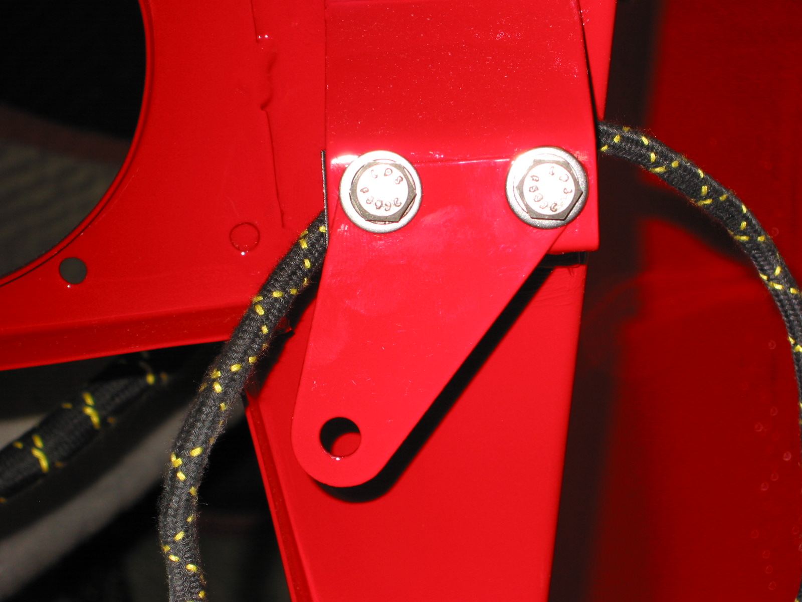
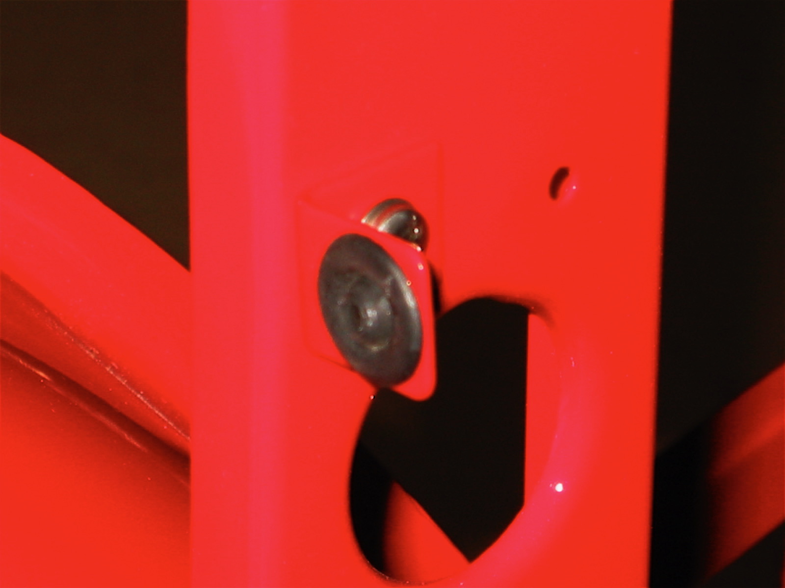
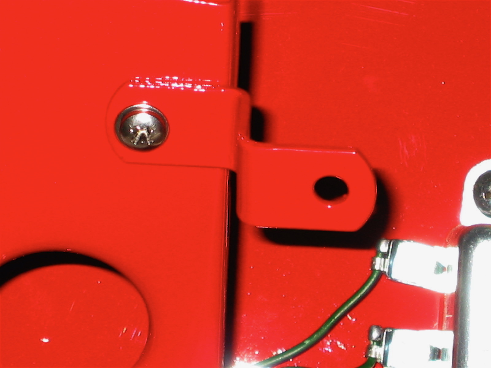
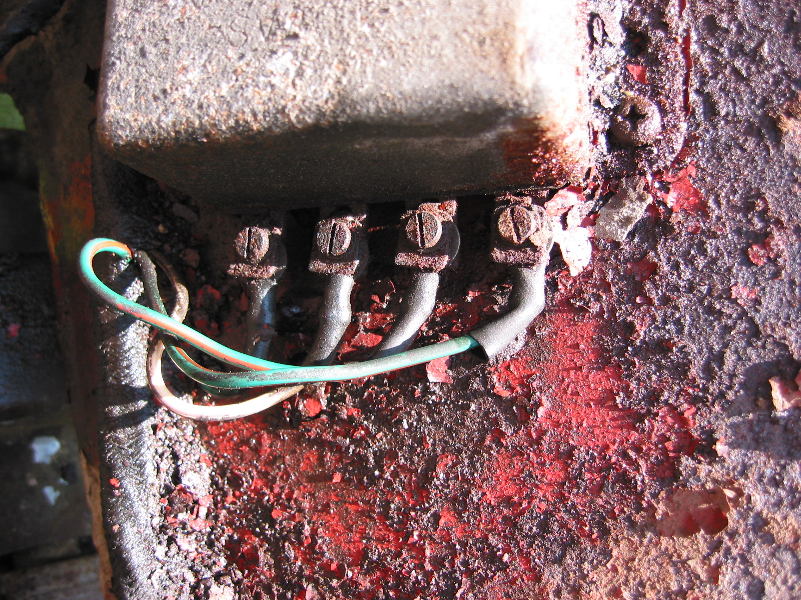
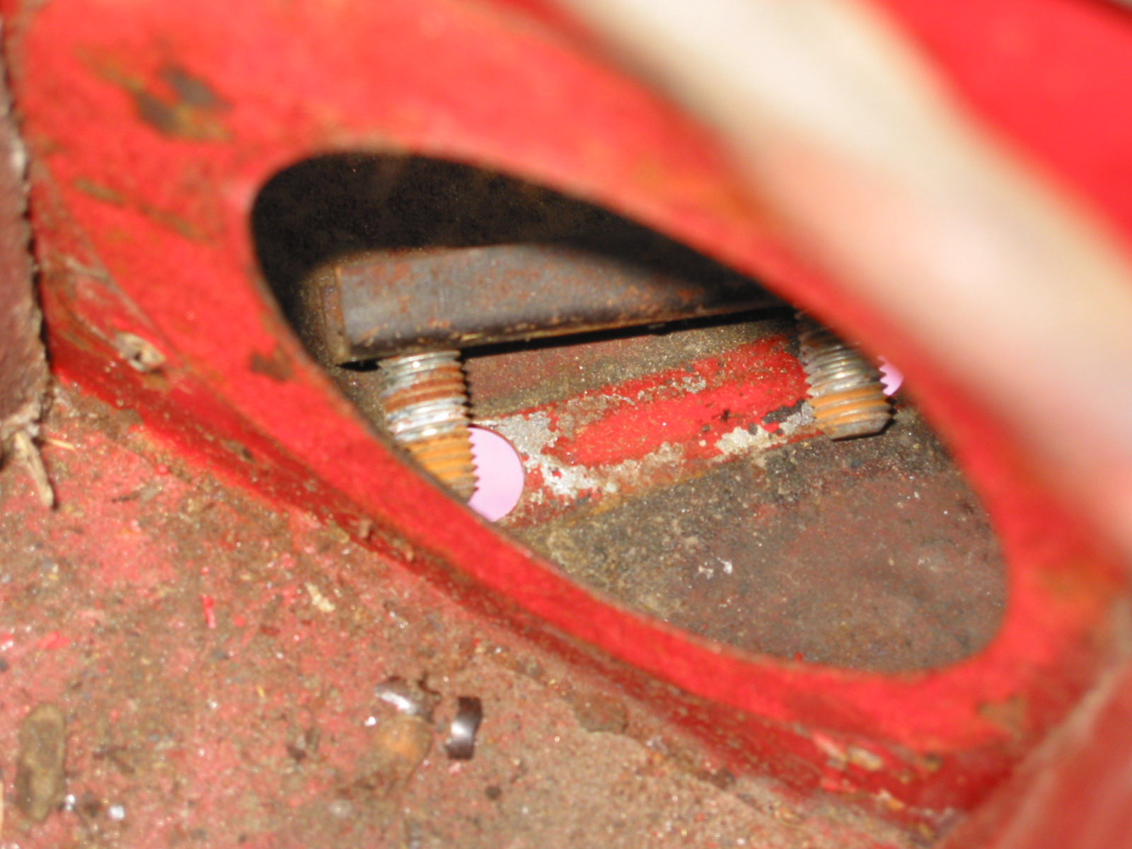
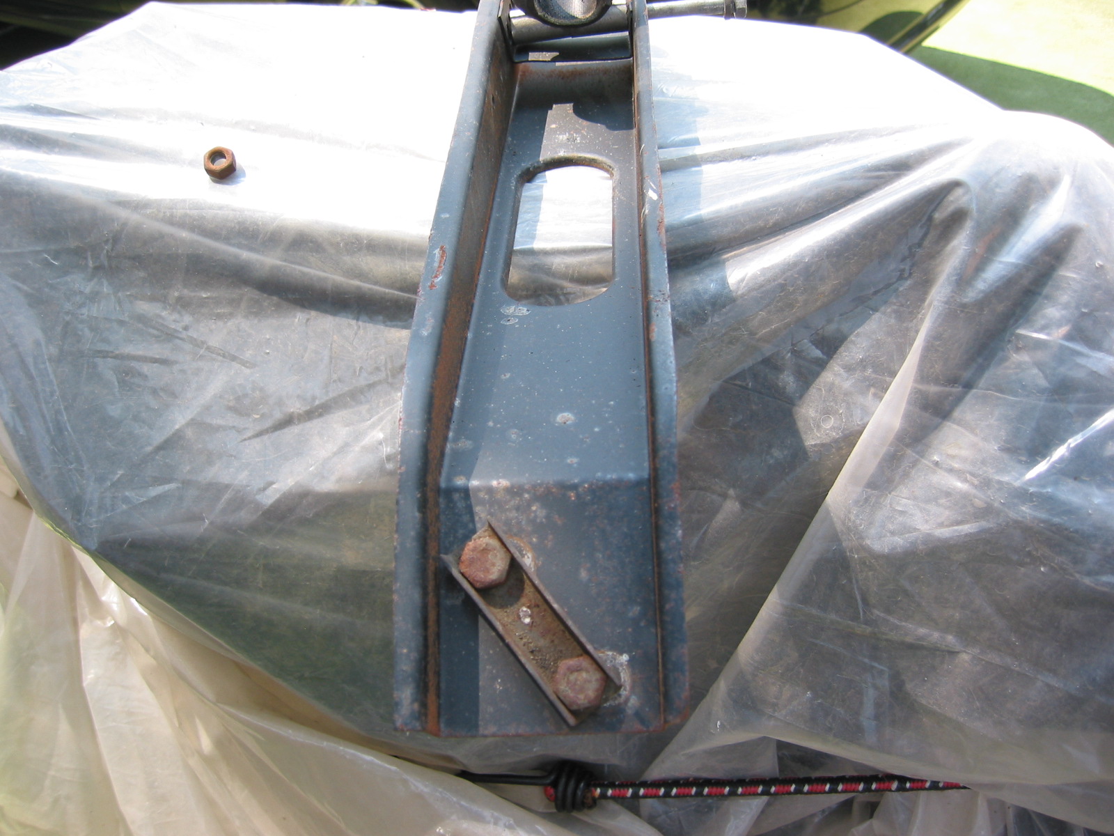
Both of the horn mounting brackets were also media blasted and painted with the POR-15 products. As the Service Manual indicates, the bracket is important in providing a ground to the horn, therefore, “Care should be taken in ensuring a good contact between the earth strap and horn bracket on the left hand horn.” The horn is secured to the bracket with two 1/4″ – 28 x 3/4″ hex head bolts with shakeproof washers and 1/4″ – 24 hex head nuts. The bracket is fastened to the bumper bracket with a single 3/8″ -24 x 7/8″ hex head bolt with both a flat washer and a shakeproof washer followed by a 3/8″ – 24 hex nut.
The LH Horn is the Low note horn and the RH Horn is the high note horn.
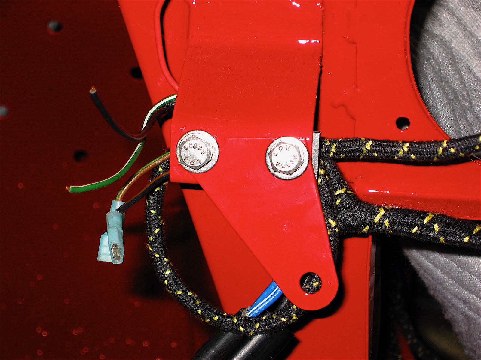
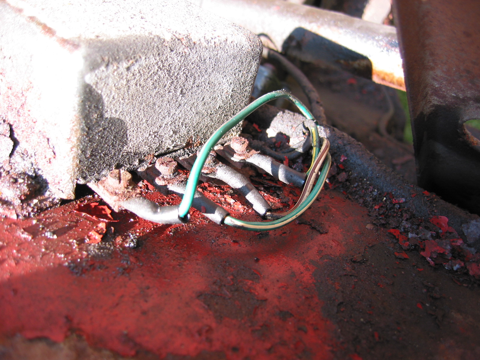
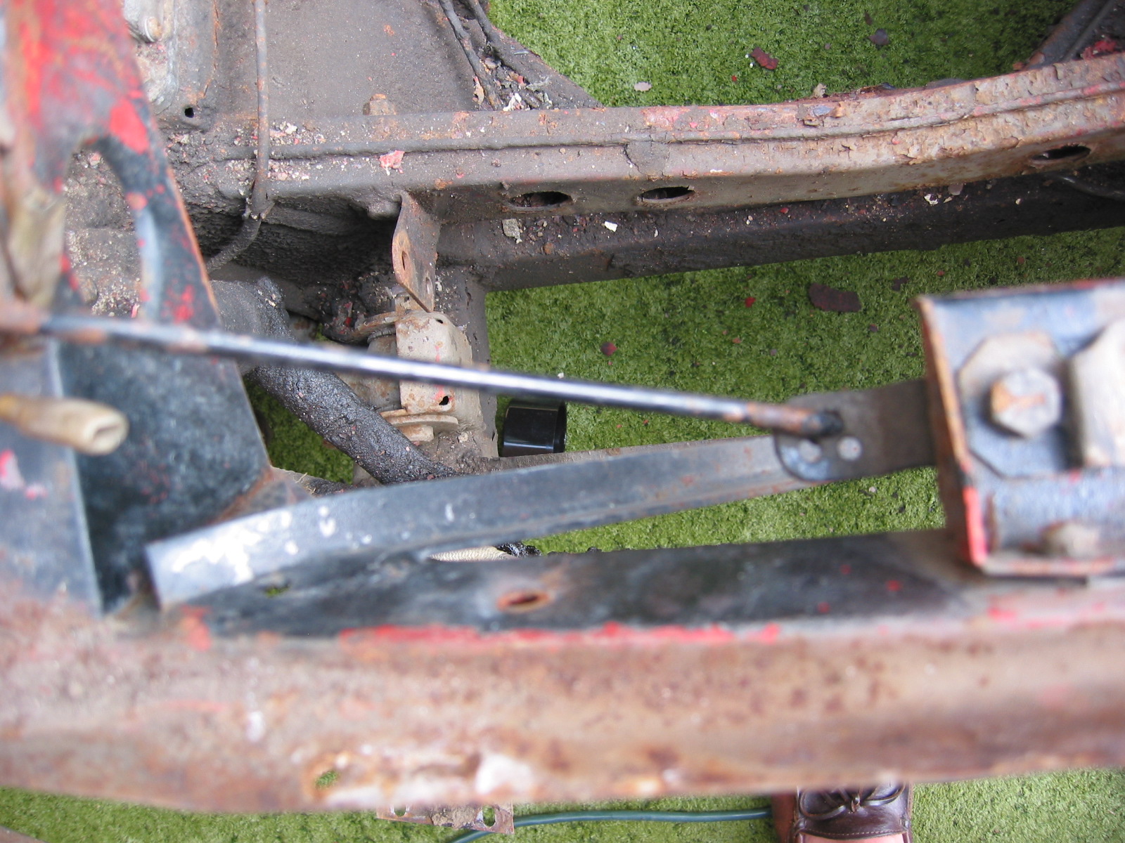
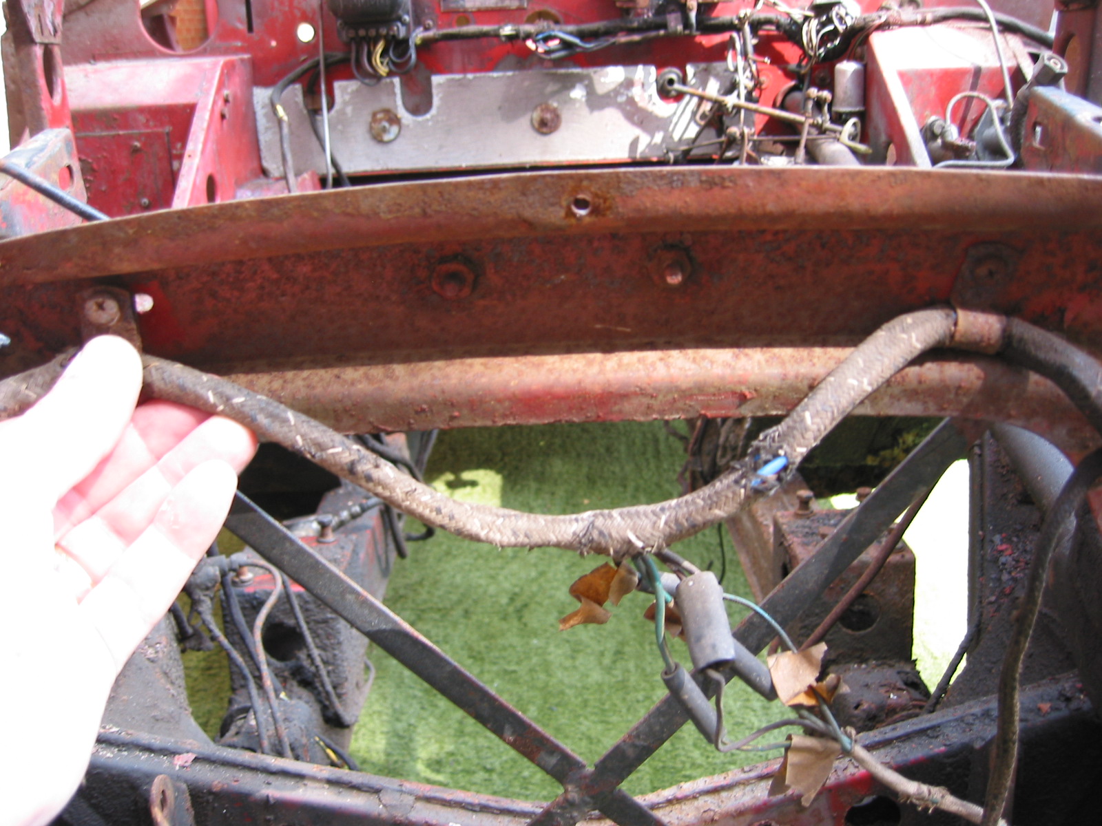
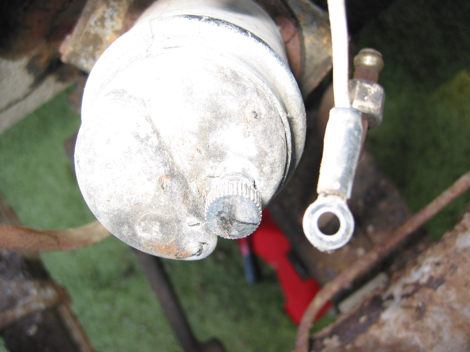
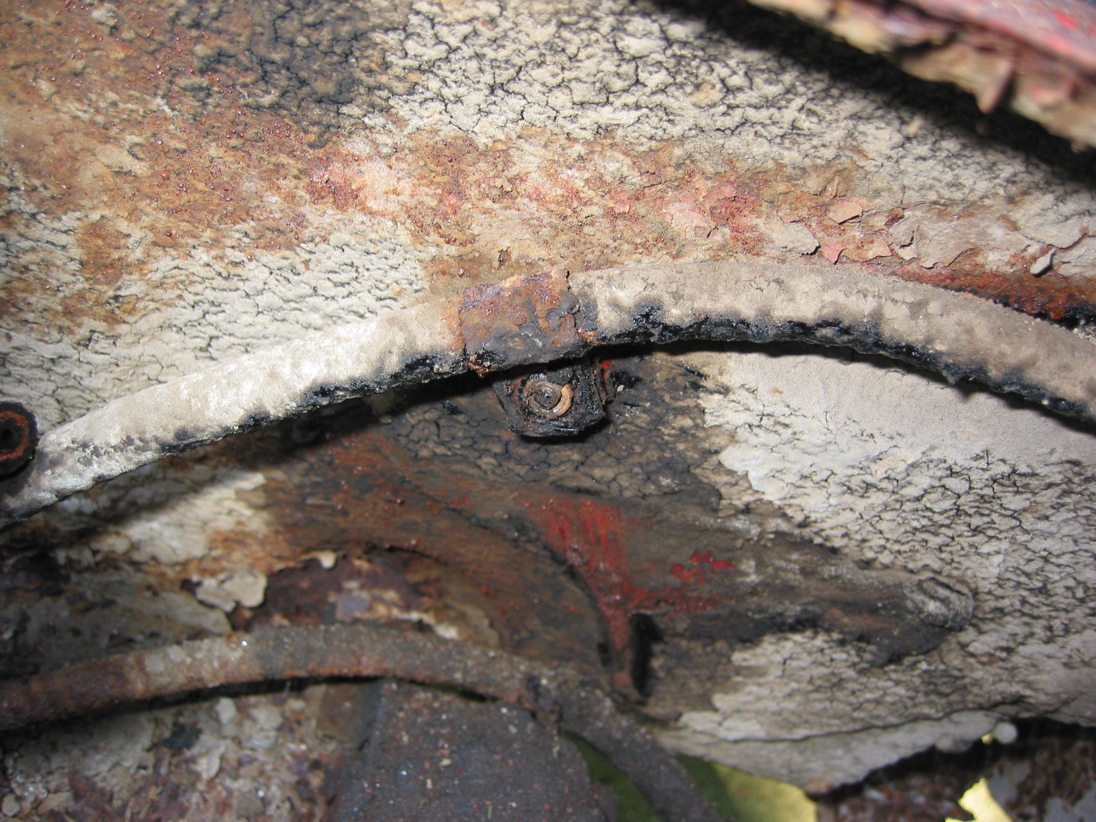
This image illustrates the connection of the ground wire to the car’s frame. the wire eyelet is fastened to the frame with a 1/4″ – 28 x 1/2″ hex head bolt, shakeproof washer and a 1/4″ -24 hex nut.

Horn Ground Wire

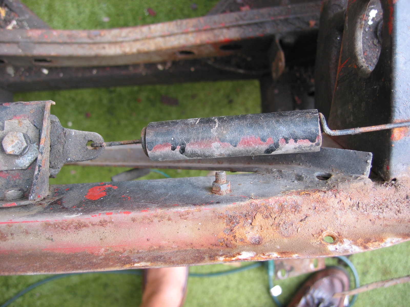
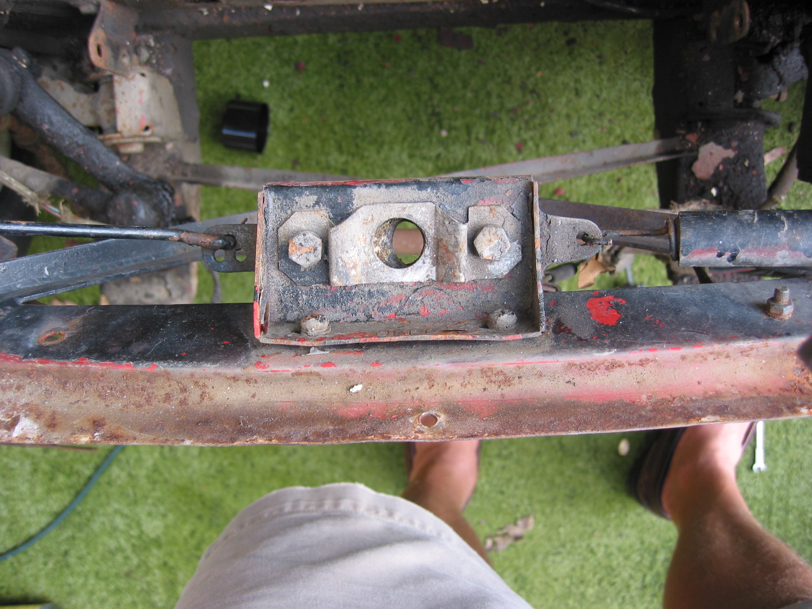
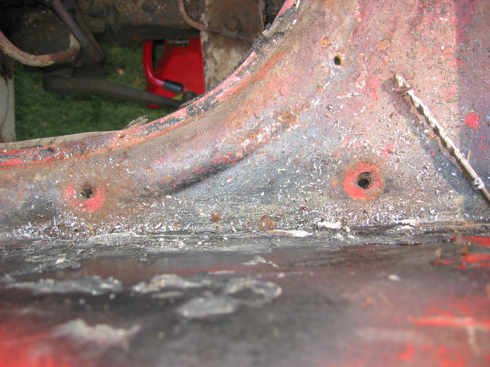
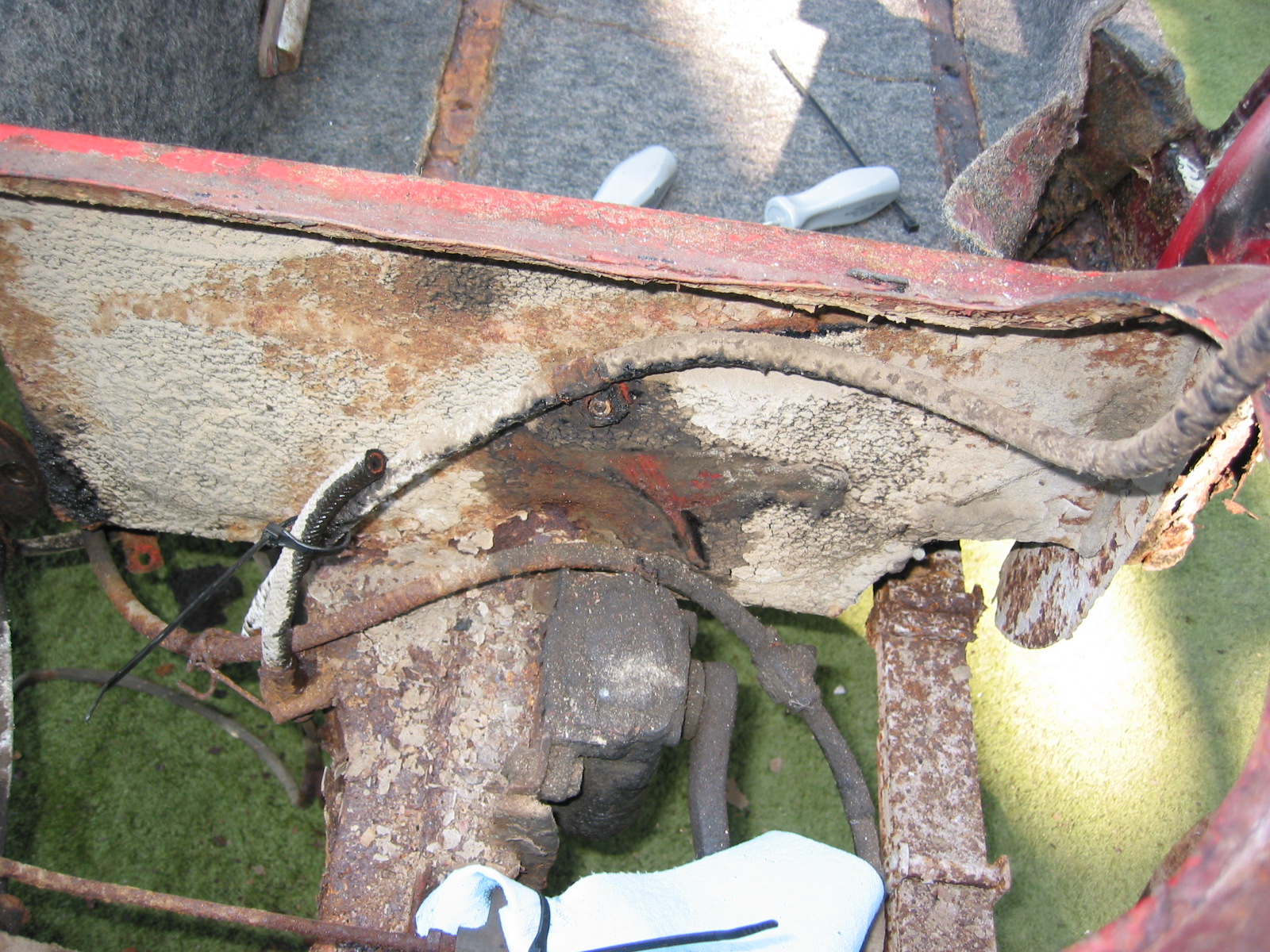
Horn Mounting Bracket
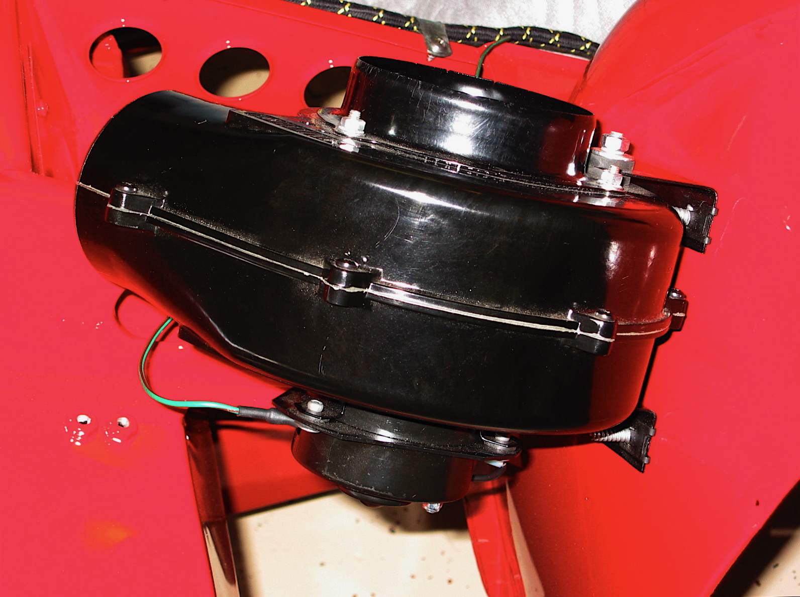
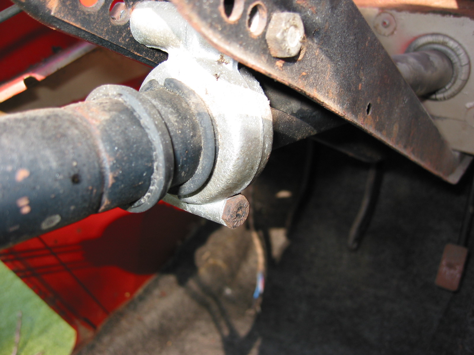
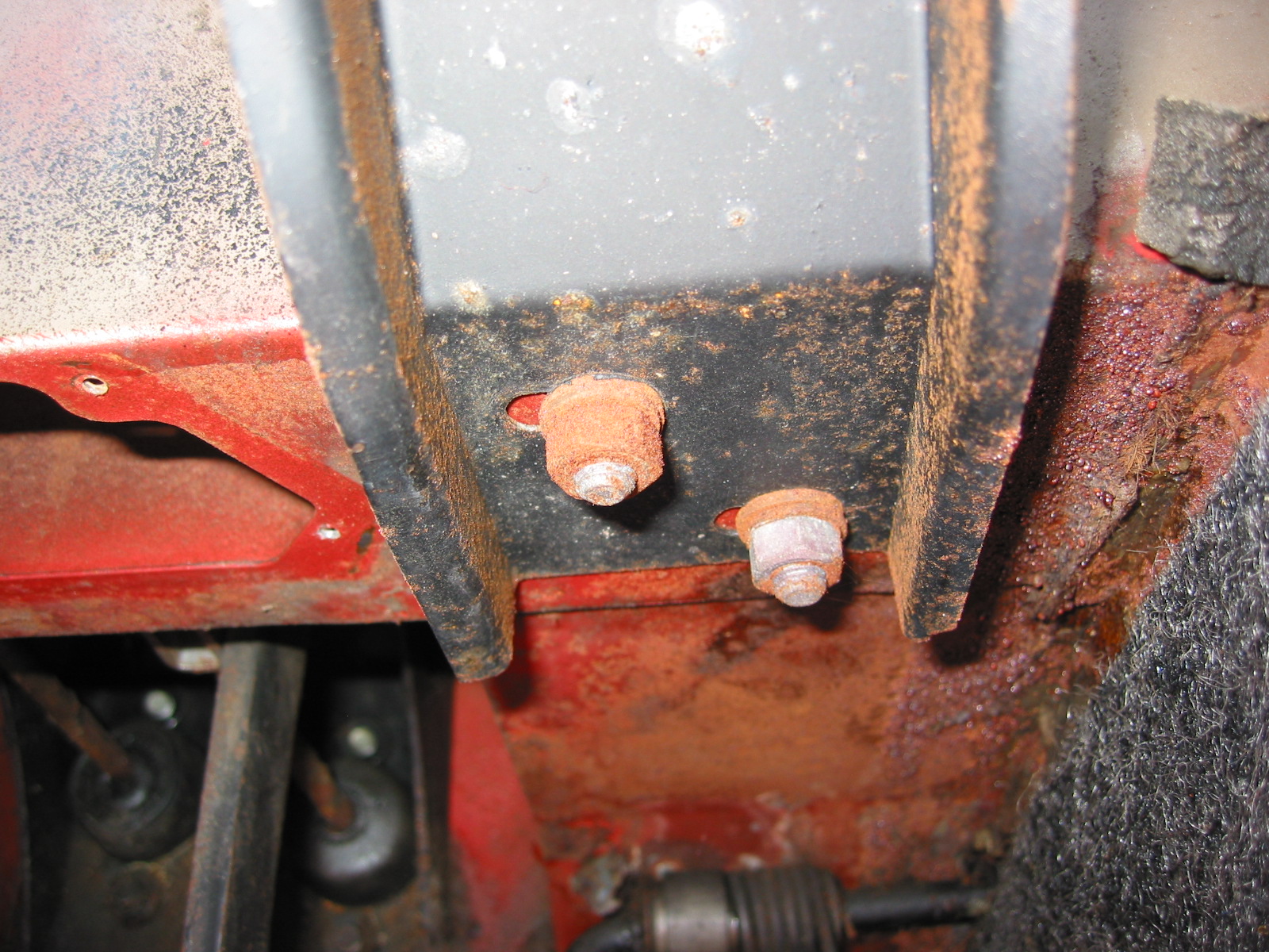
This image illustrates mounting and orientation of the horns below the radiator:

Horn Orientation
Headlamp Dipper Switch
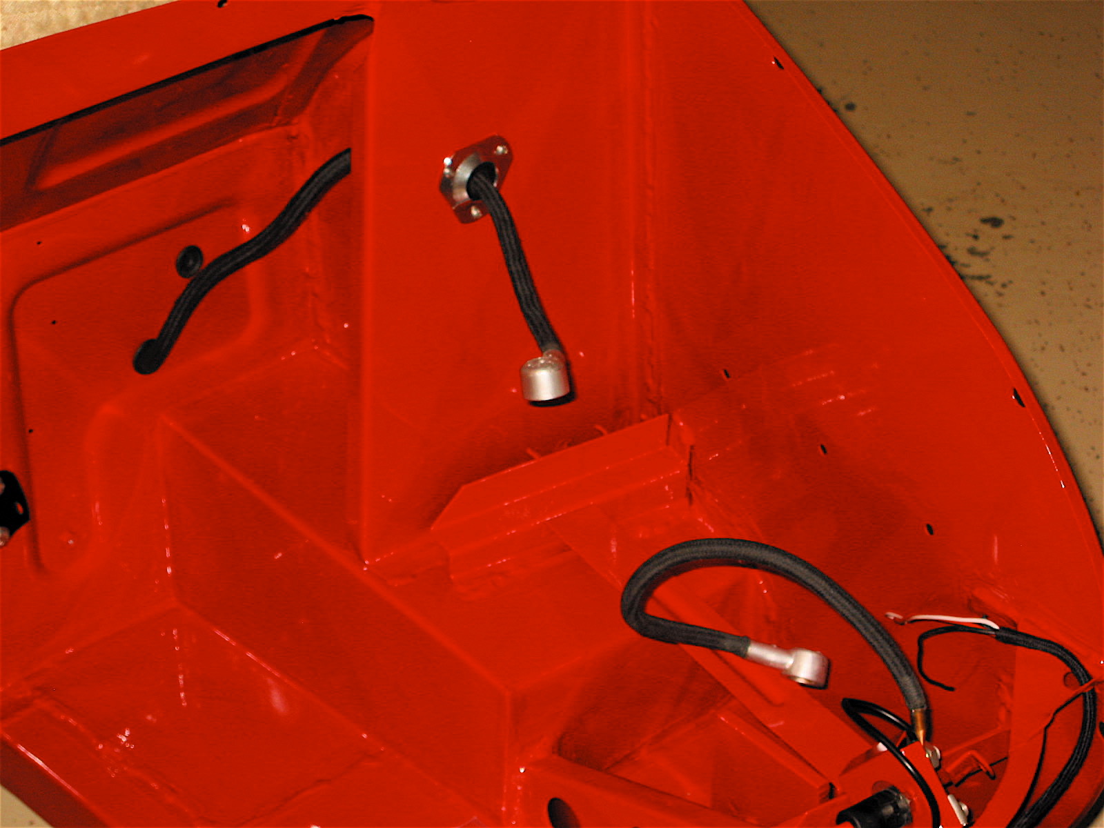
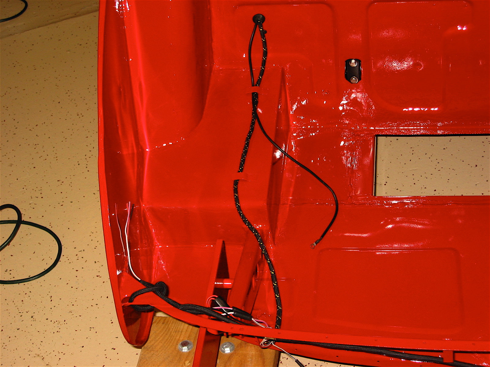
The Headlamp Dipper Switch was in good condition and was cleaned for reuse. The switch is secured to the floorboard with two #10 – 32 x 1 7/8″ hex head bolts through distance pieces with shake proof washers. A rubber cap is pushed over the end of the foot switch.
The upper part of the switch base plate is the shorter side with the mounting screw hole offset to the right. This orientation is instructive for the proper location of the switch wiring on the three terminals. The terminal farthest to the right has the blue/red single wire, the lowest terminal (closest to the floor) has the single solid blue wire, and the left most terminal has two blue/white wires.
Headlamp Dipper Switch
Dipper Switch Wiring

Headlamp Dipper Switch
Headlamp Dipper Switch
Renewed Dipper Switch
Renewed Dipper Switch
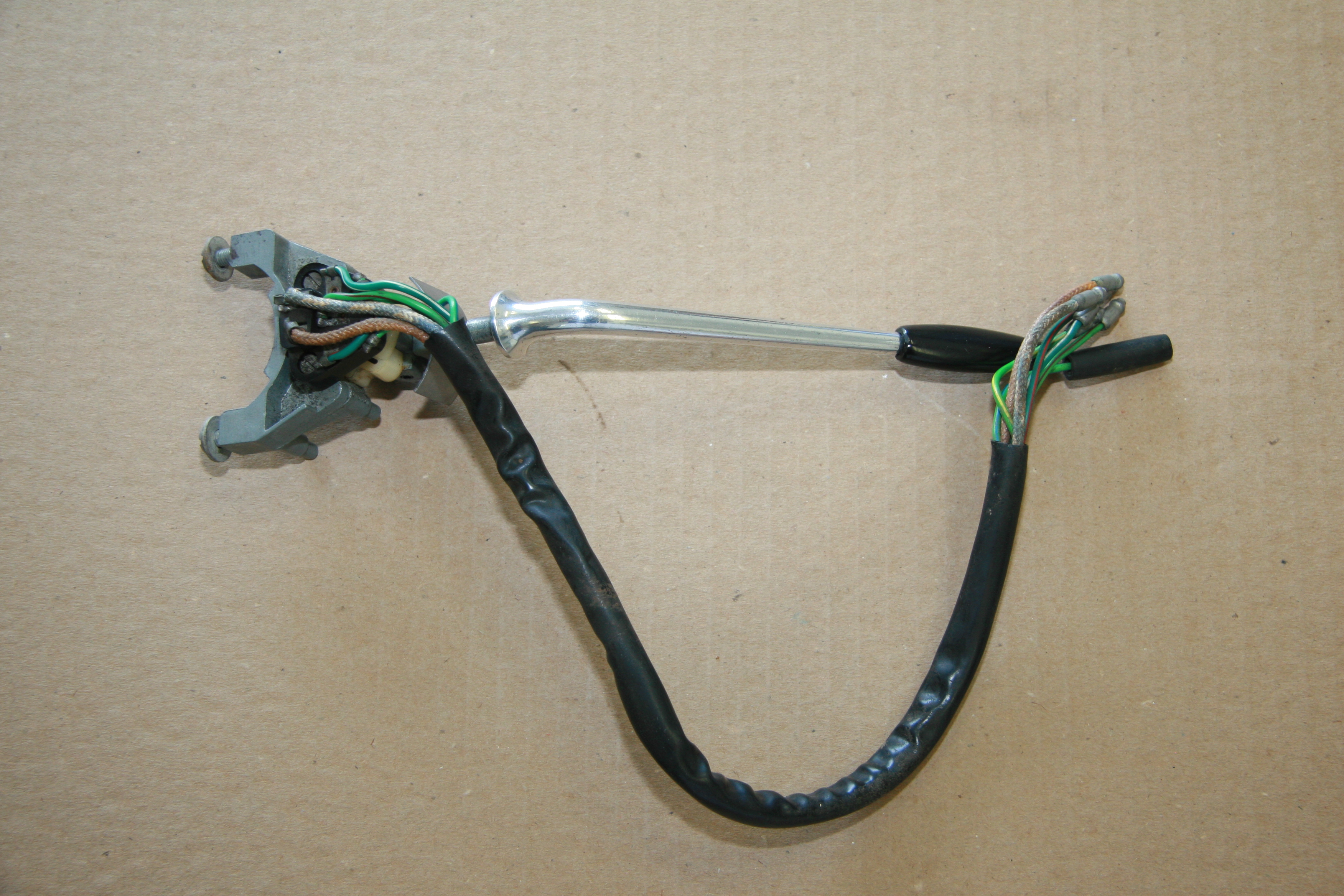
Direction Indicator/Headlamp Flasher
My MK2 has a Model 85 unit. I cleaned the assembly. The wiring appeared to be in very good condition but the nylon “spring” that catches the arm in the left or right position was broken.

Direction Indicator/Headlamp Flasher Switch
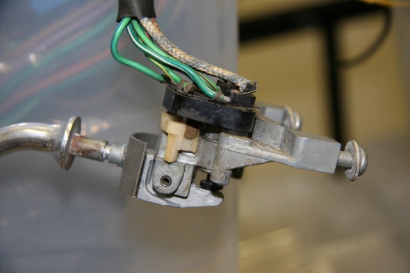
Turn Indicator Flasher Side View
There was a time when Lucas made and sold repair kits to replace the nylon spring. Today they are a challenge to find but they do come up on ebay from time to time. I was able to purchase two of the repair kits. The kit includes the spring and the rivet used to hold the components together.
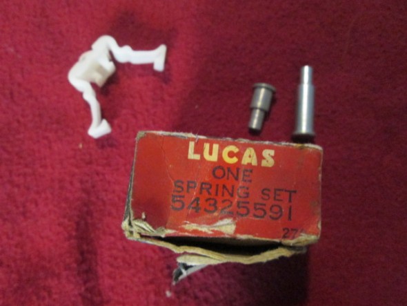
Lucas Turn Indicator Spring Set

Turn Indicator Nylon Spring
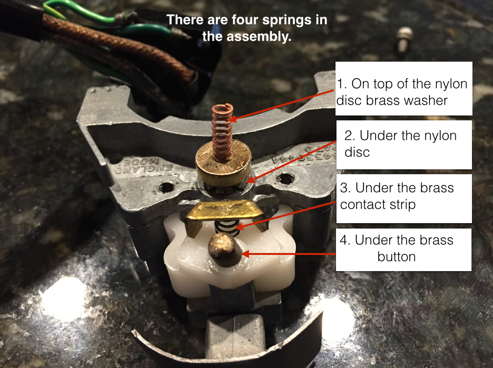
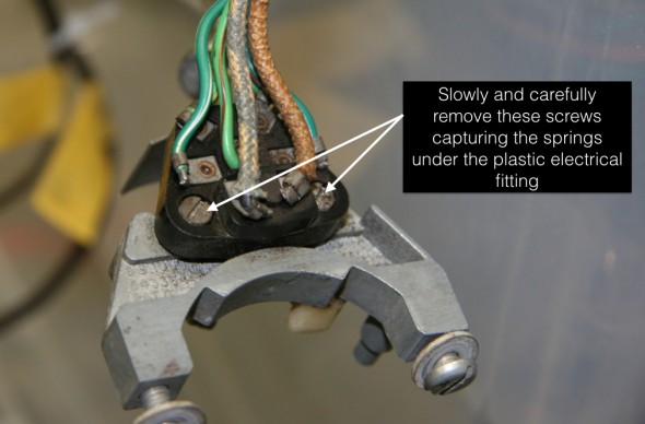
To replace the spring one removes two slotted screws from the plastic electrical fitting. This must be done carefully as there are a total of four springs between the aluminum housing and the plastic fitting.
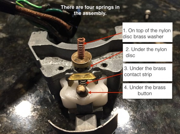
Turn Indicator Springs
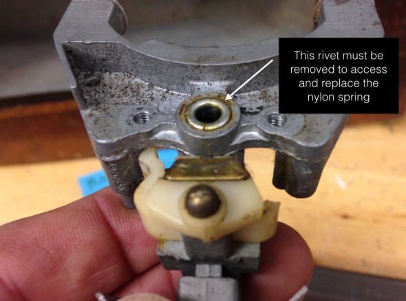
Once the electrical fitting is removed one has access to the rivet that must be drilled/cut out.
Turn Indicator Disassembly
Turn Indicator Rivet
It is a tedious and somewhat challenging task to install the new rivet. I actually visited Mike Gassman of Gassman Automotive to help me with the install.
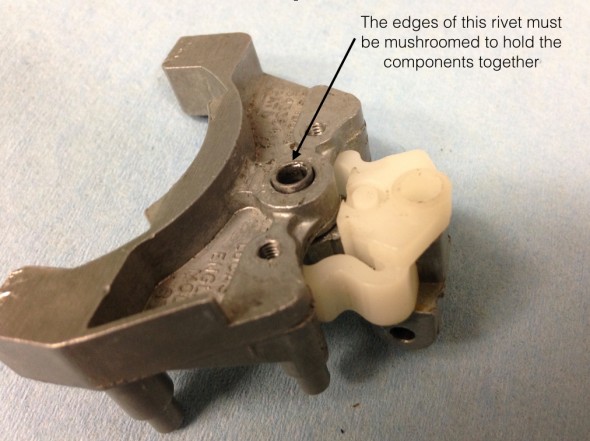
Turn Indicator Rivet
I held the assembly in place over a steel rod while Mike used several punches to get the job done. We didn’t do as well as the factory but we succeeded.
After placing all of the electrical contacts, springs and nylon/plastic components in their proper place one carefully places the black electrical fitting over the assembly and compresses carefully while a friend (spouse) inserts and tightens the two screws that hold the assembly together. This little piece consumed a lot of energy and time, but now functions as new!
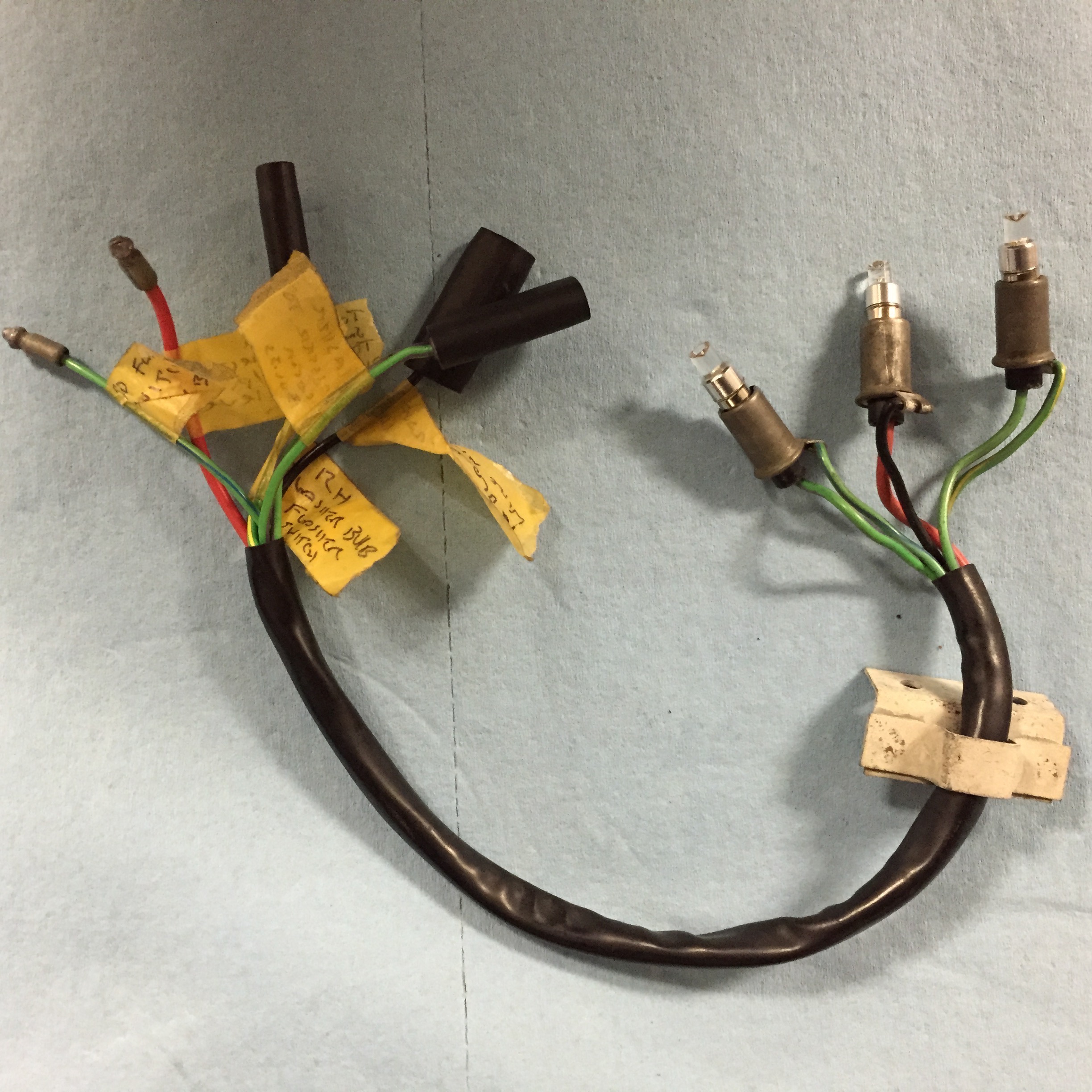
Turn Signal Indicator Lights
The MK2 used a short pigtail harness to connect the turn signal switch, the flasher relay and the indicator bulbs located on the steering column. My original harness was in very good condition and will be reinstalled after cleaning. Three warning bulbs are provided in the harness.
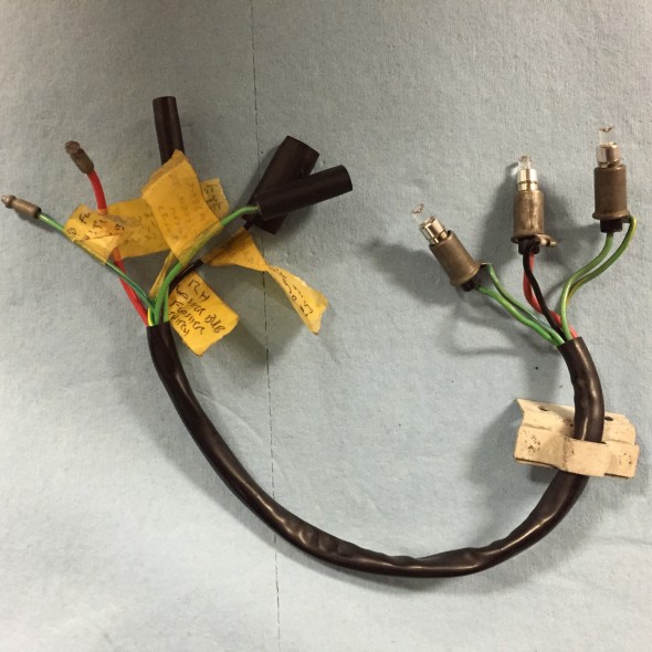
Turn Signal and Overdrive Indicator Bulbs, Holders, and Pigtail
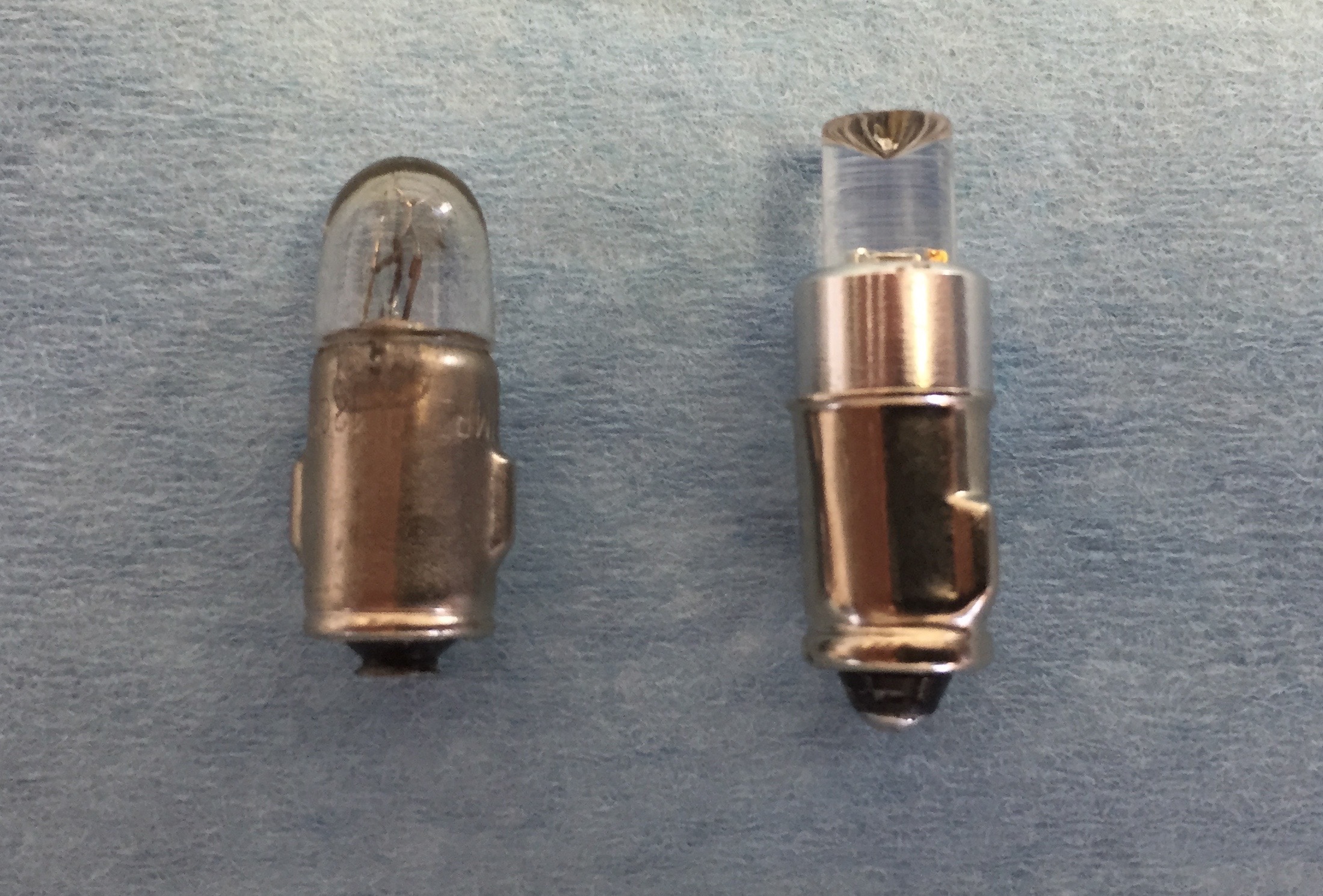
The LH bulb for the LH turn signal, the center bulb to indicate overdrive engagement and the RH bulb for the RH turn signal. The two turn signal indicator bulbs are replaced with green BA7 LED micro bayonet bulbs and the overdrive bulb is a clear white BA7. Bulbs were sourced from 4sightautomotive lighting at http://www.bettercarlighting.co.uk. This image shows the original bulb as well as the LED replacement:
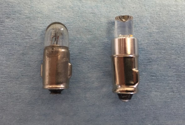
2 Watt Liliput Turn Signal Indicator Bulb and Replacement BA7LED Green Micro Bayonet Bulb
I am also using LED flasher bulbs at each of the four corners of the car. Using the LED bulbs requires a LED flasher relay that is incorporated into the Classic Technologies Relay/fuse panel that I am using for my electrical system. The pigtail is held in place by a small bracket located on the backside of the LH Fascia Board Assembly and the bulbs plug into the Upper Switch Cover Assembly at Centre of Steering Wheel.

Turn Signal and Overdrive Indicator Bulbs, Holders, Pigtail and Mounting Bracket on LH Fascia Board Assembly
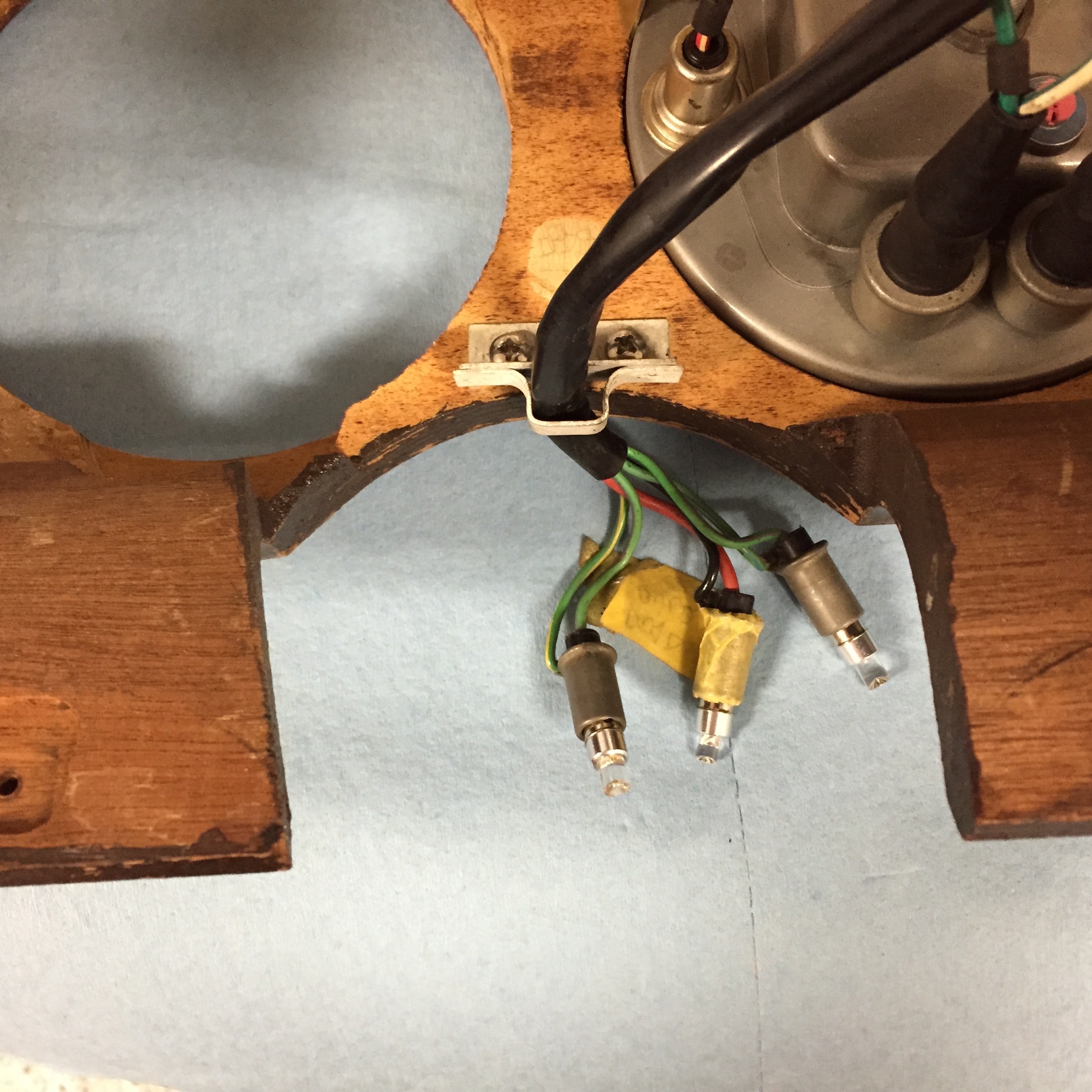
Overdrive Operating Switch
This switch which activates the electric overdrive is located on the right side of the steering column. Power is derived from fuse position #14 on the CT fuse box. With lever activation a signal is sent to the overdrive interlock, or top gear switch located on the top of the gearbox and then to the overdrive solenoid. A warning indicator bulb is illuminated when the overdrive is engaged.
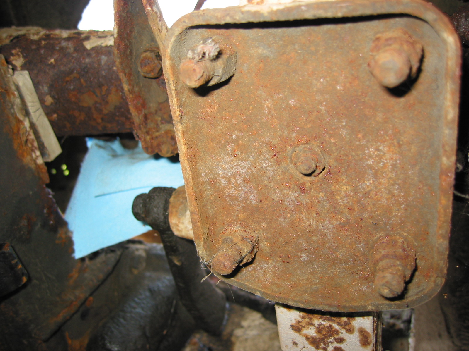
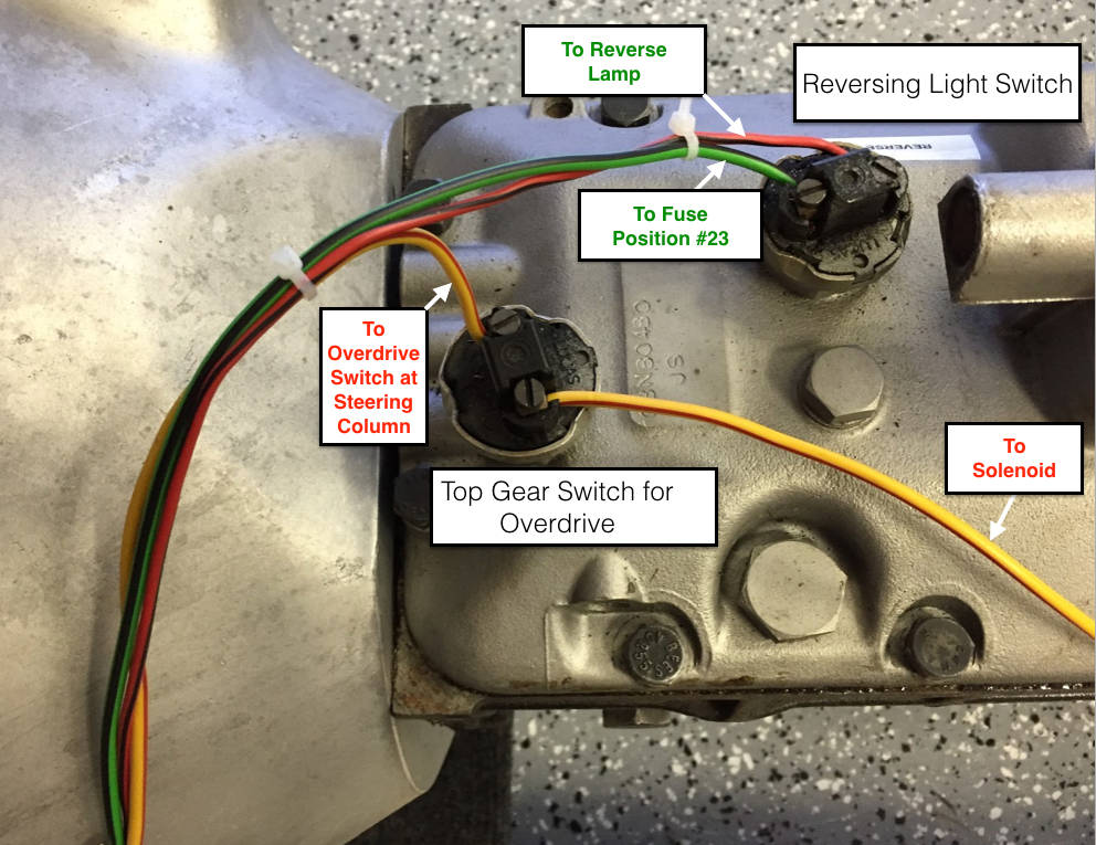
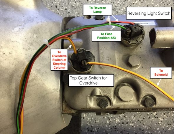
Switch, on Gearbox Top Cover, Operating Reversing Light and Top Gear for Overdrive Unit
These two switches are identical. As indicated, both are located on the gearbox. I purchased new switches, but found after testing that both original switches worked fine so I left the original switches in place.
Overdrive Interlock or Top Gear Switch at gearbox
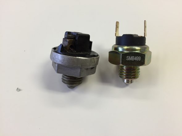
Original and New Lucas Overdrive and Reverse Switch
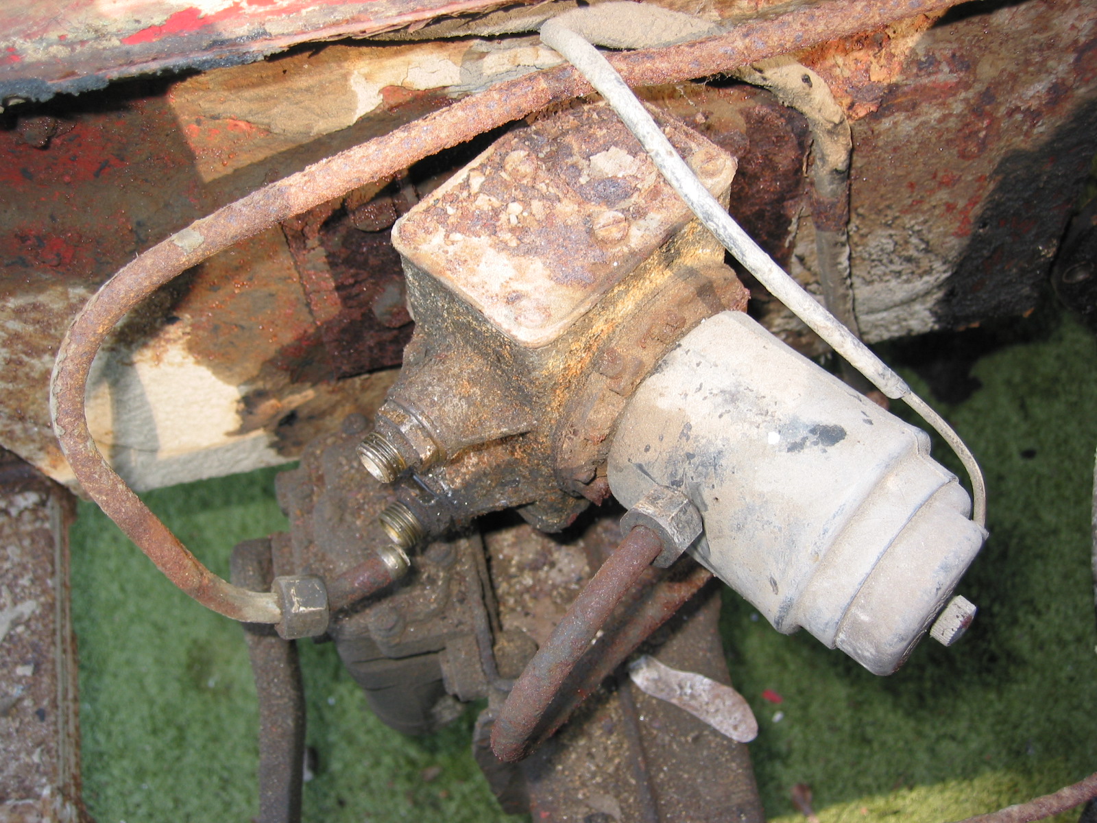
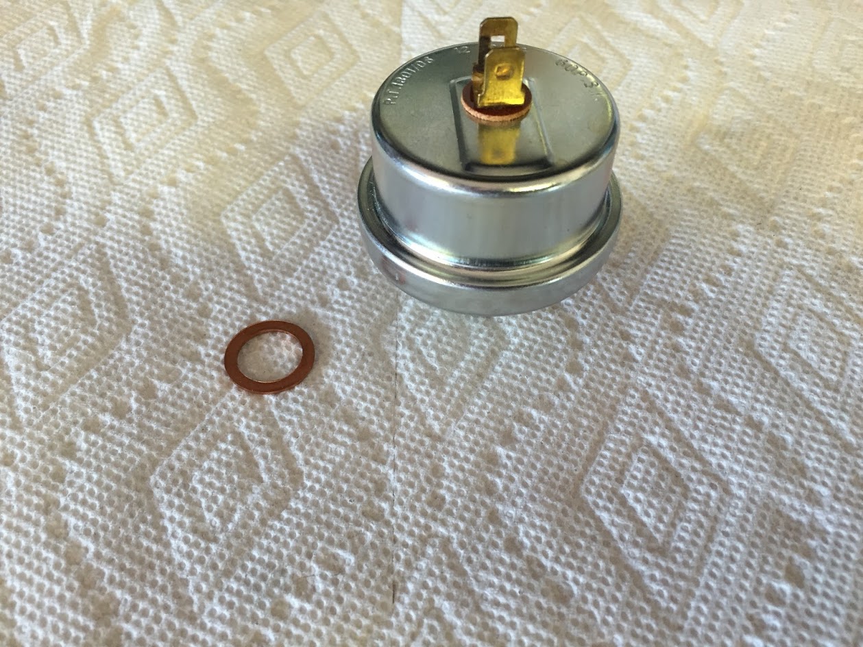
Oil Pressure Element
The Oil Pressure element or sensor is located directly above the Oil Filter Assembly on the RH side of the cylinder block. I replaced the element with a new Lucas item.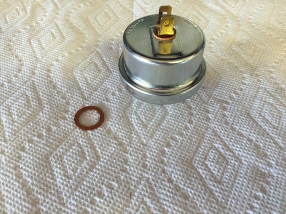
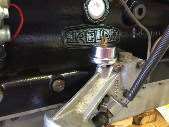
Oil Pressure Element Mounted