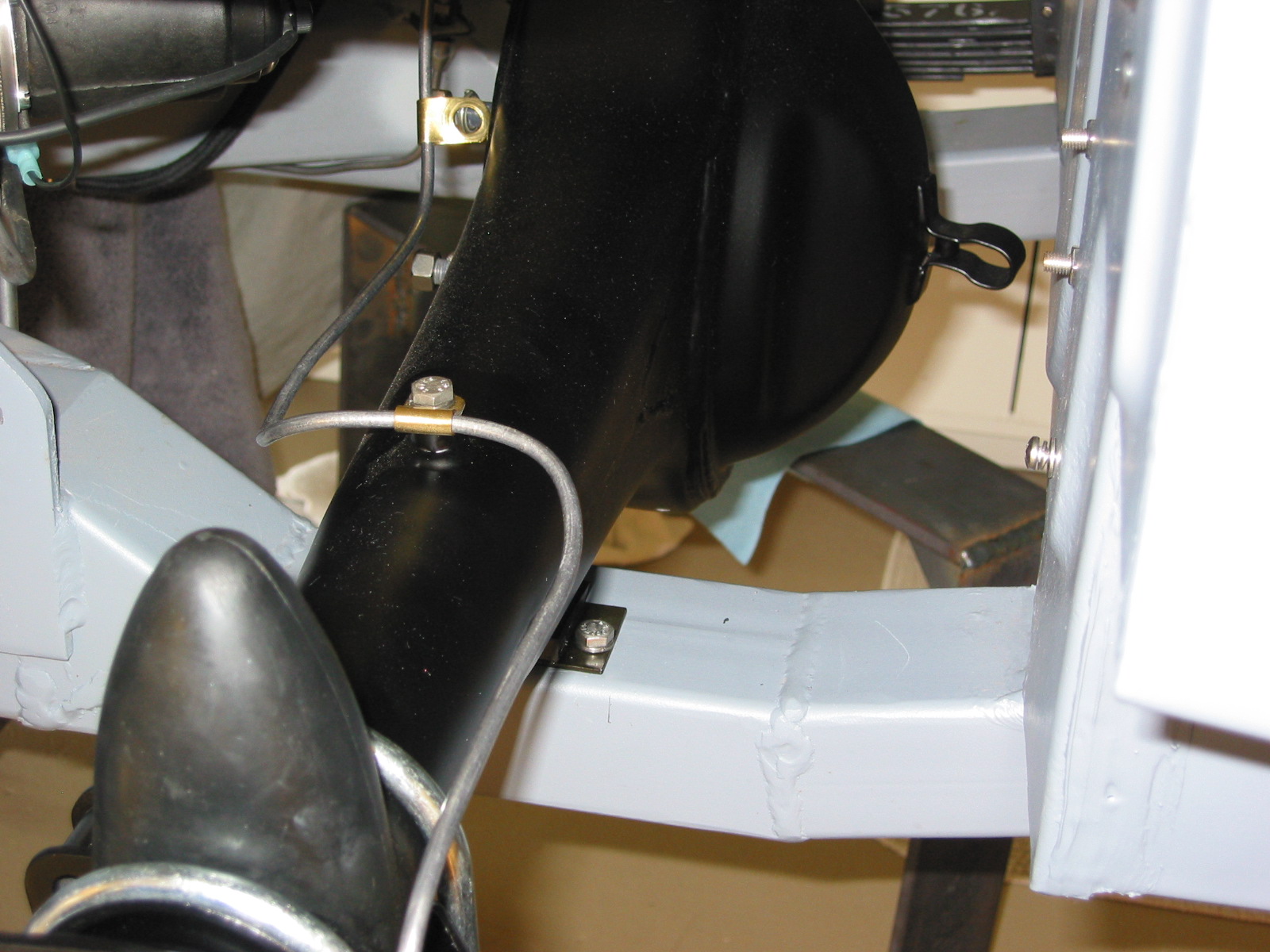
Fresh Air Intake Assembly – Three screws, two with nuts and one welded onto the tube secure the assembly to the superstructure. Disconnected the air control cable.
Fresh Air Intake Assembly
Fresh Air Intake Assembly
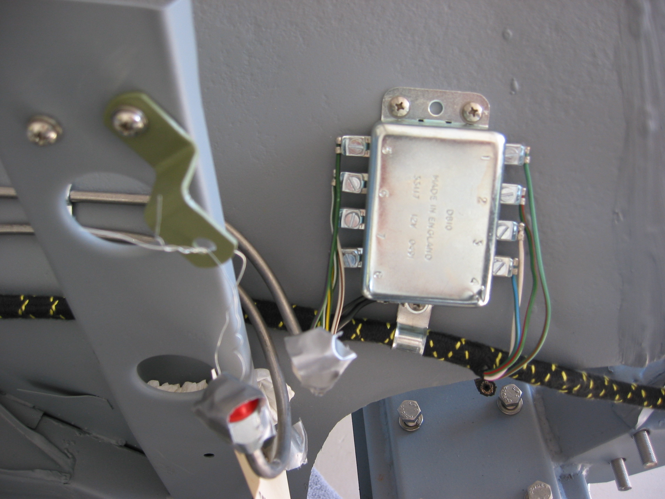
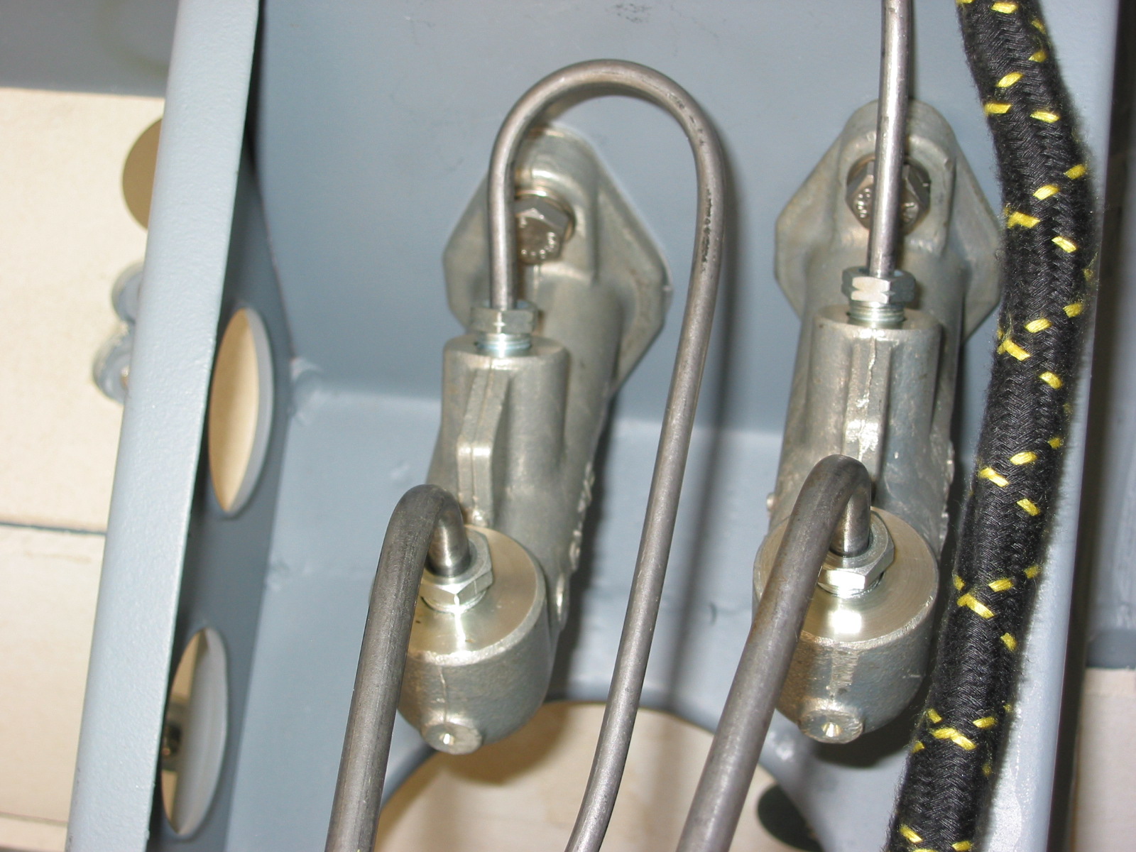
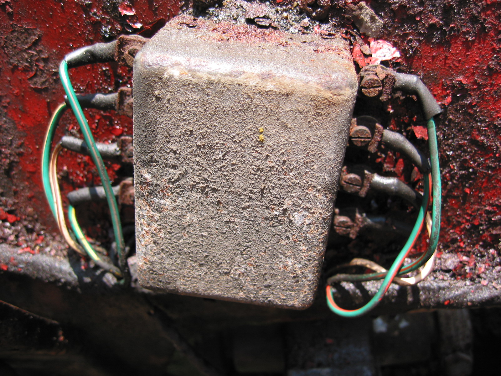
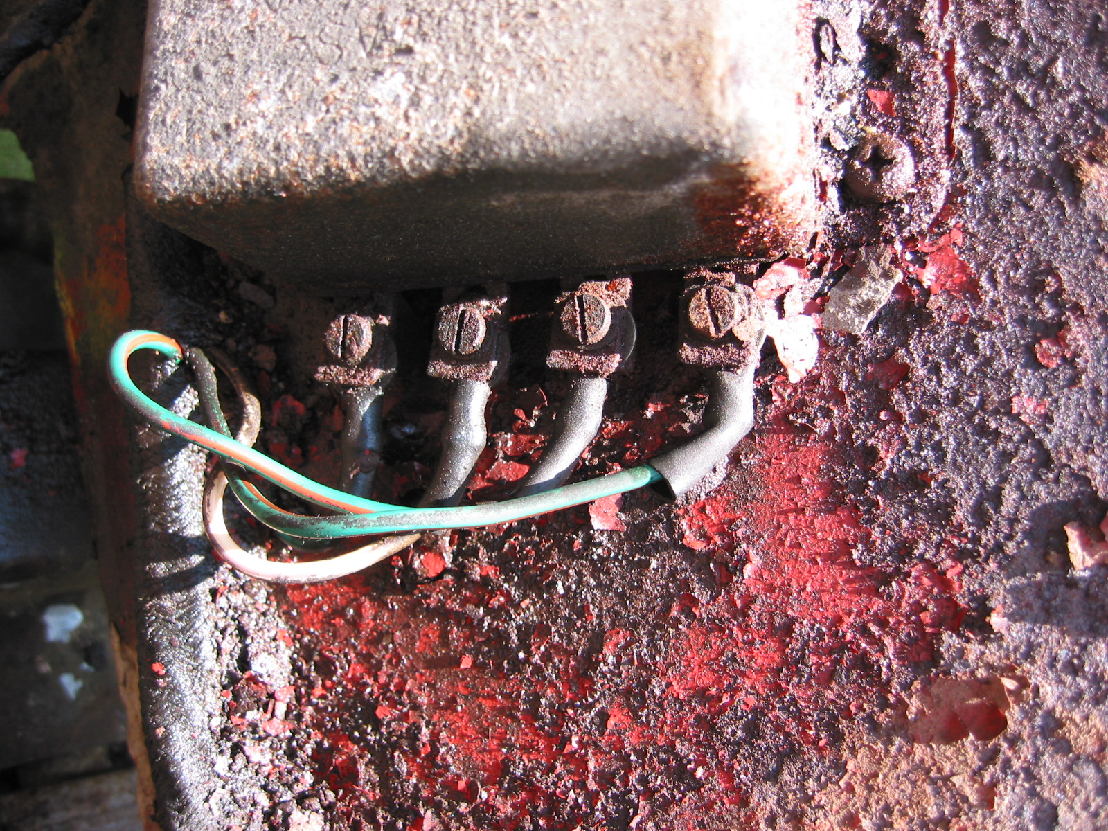
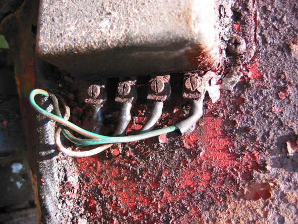
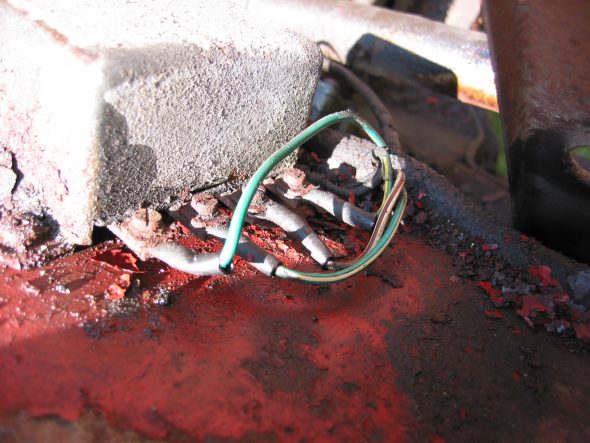
Flasher Relay – Two cross head screws on top, one on bottom. All have nuts welded on the outside of the wheel well. The bottom screw also holds a wiring harness clamp and the ground wire. Starting from top left and going down – first wire is green with pink stripe, second is green/white stripe, third is white/brown stripe, and fourth is green/yellow stripe. Starting from the right top and going down – first wire is green/brown stripe, second is green/red stripe, third is white/purple stripe and fourth is green/? Stripe. Black ground wire is at bottom.

Flasher Relay Wiring 1
Flasher Relay Wiring 2
Flasher Relay Wiring 3
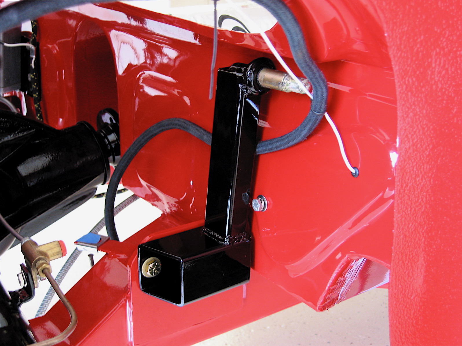
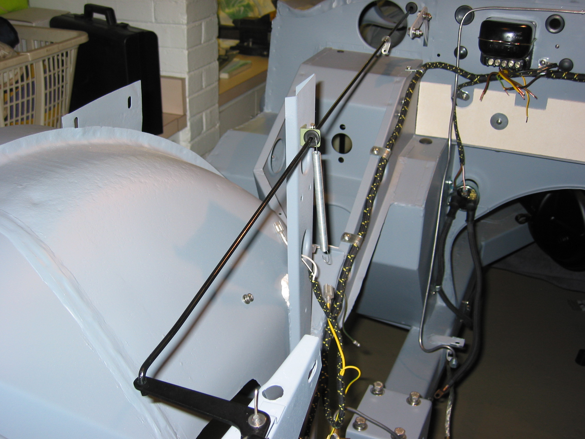
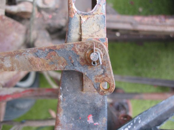
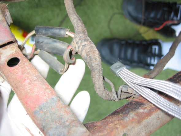
Bonnet Latch Support Bracket, Lever and Spring – Note that the left side of center has a rubber tube over the spring and extension rod.
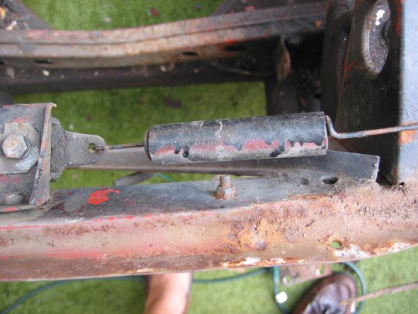
Bonnet Latch Return Spring

Bonnet Latch Rod
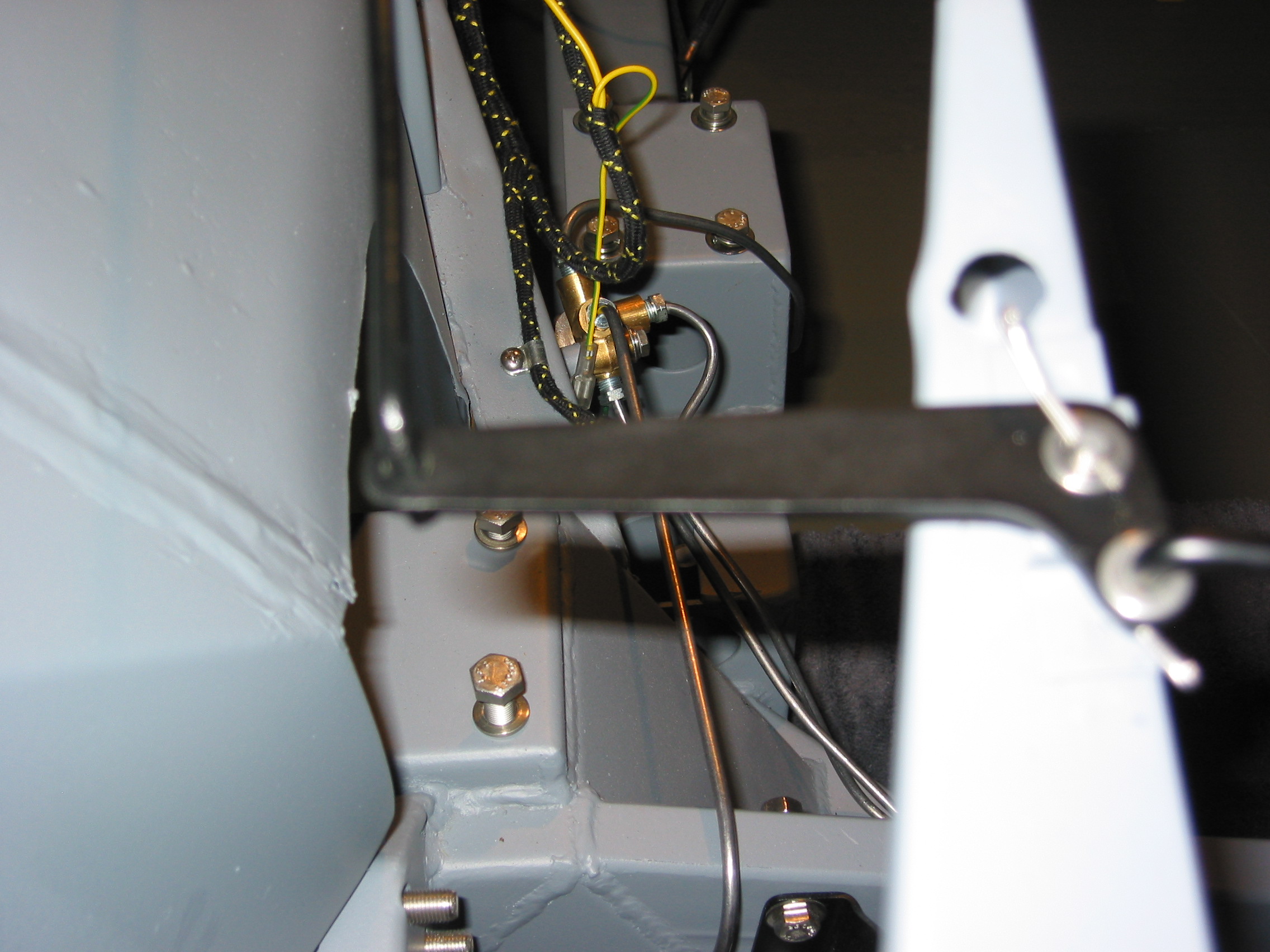
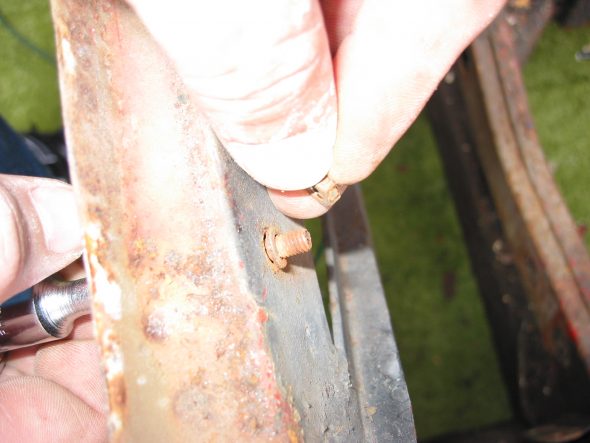
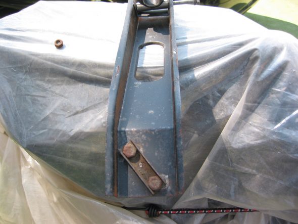
Bonnet Latch Support Bracket – The bracket is secured by two bolts and nuts.
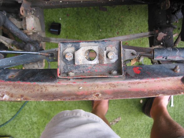
Bonnet Latch Support Bracket
Bonnet Latch Return
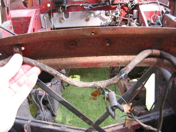
Wiring harness extension for lights and horns – Two clamps located by screws and nuts at the front of the car.
Wiring Harness Clip Screws
Wiring Harness at Front of Car
August 3, 2002
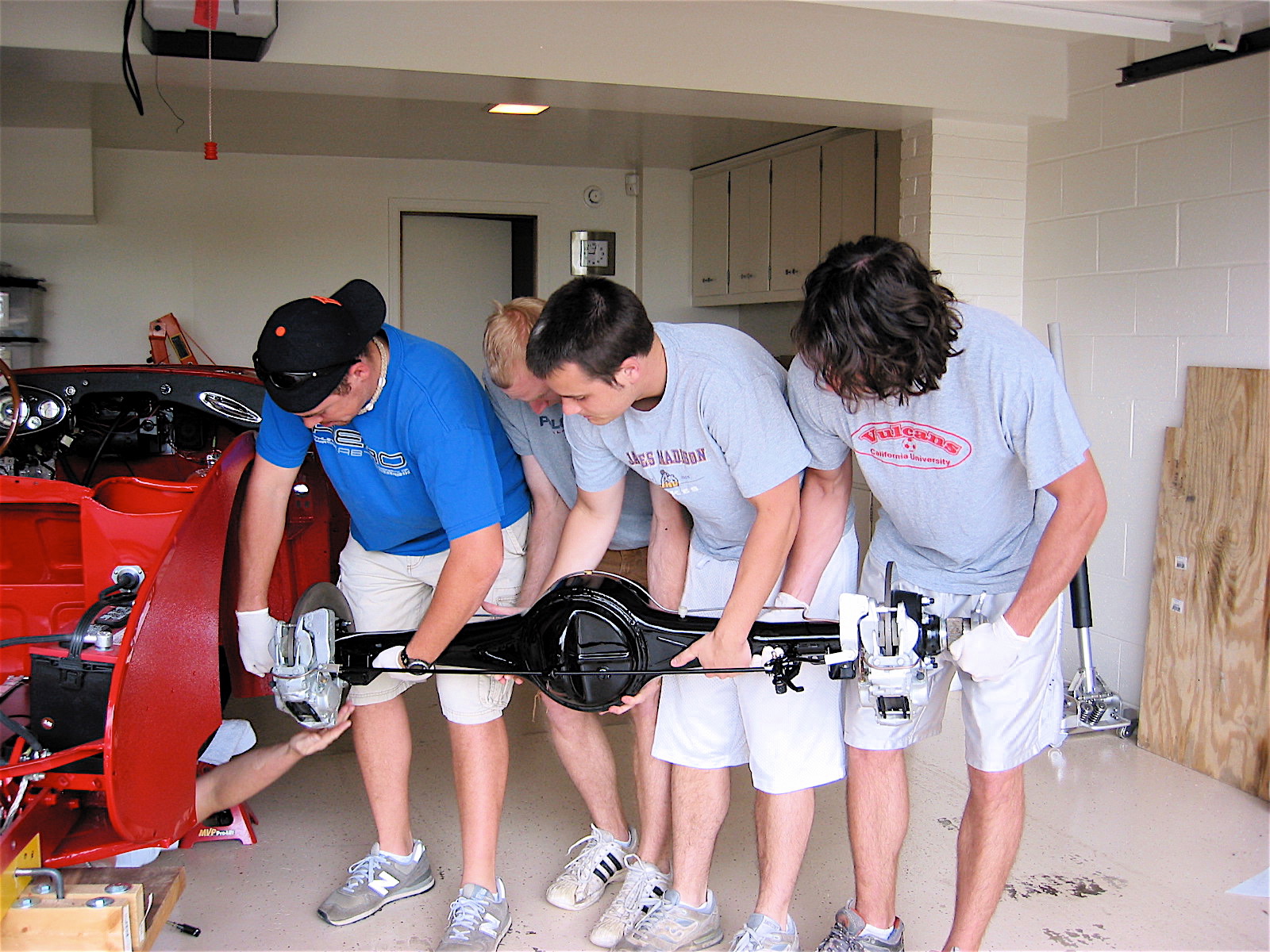
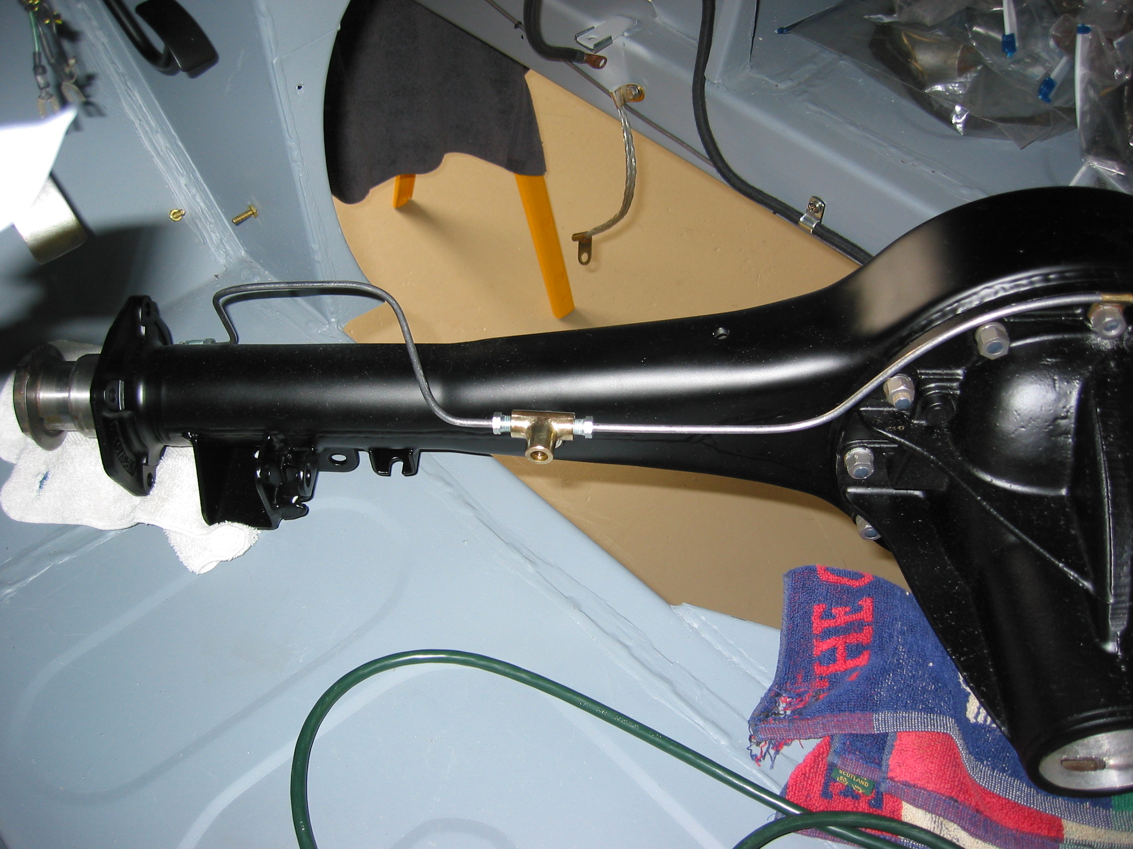
Rear Axle and Related Assembly
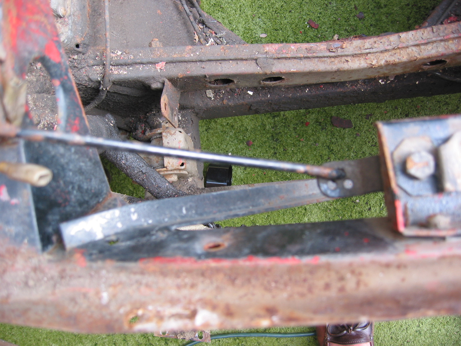
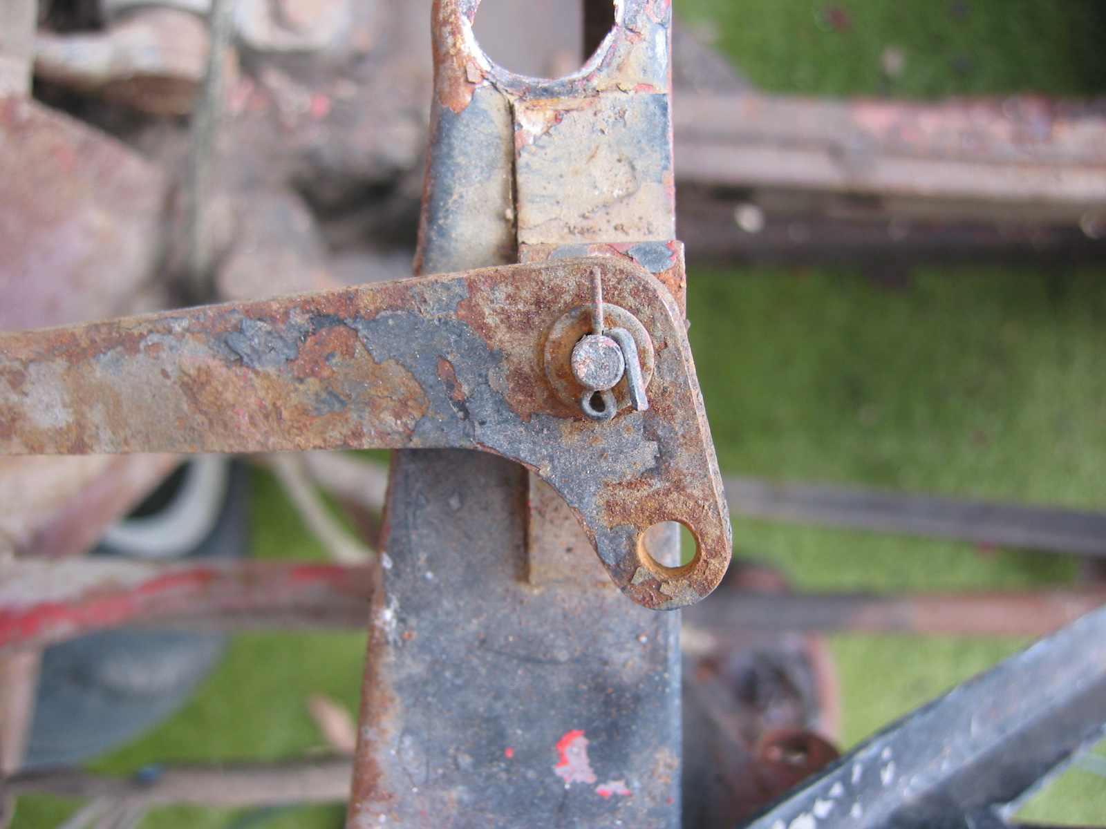
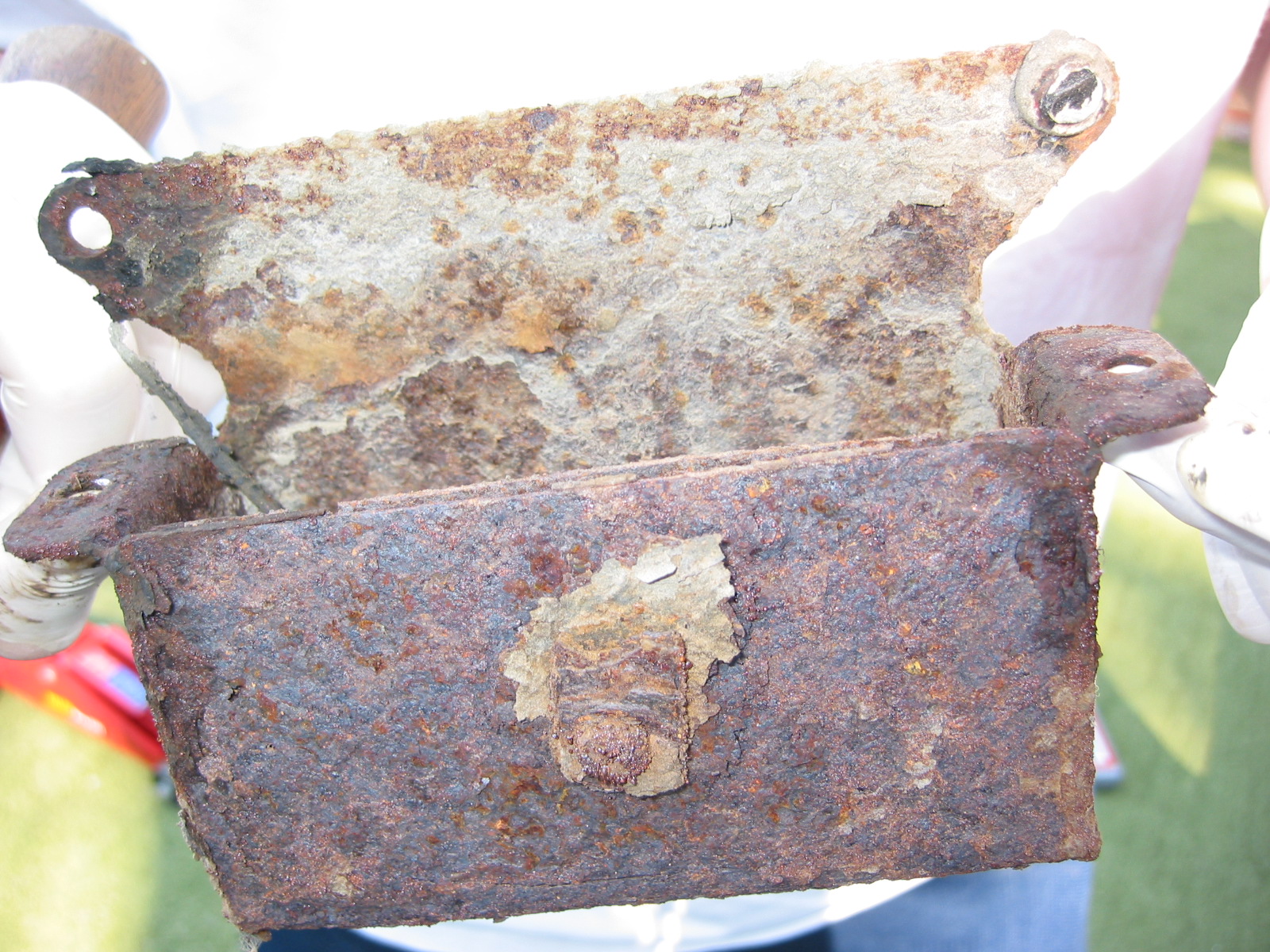
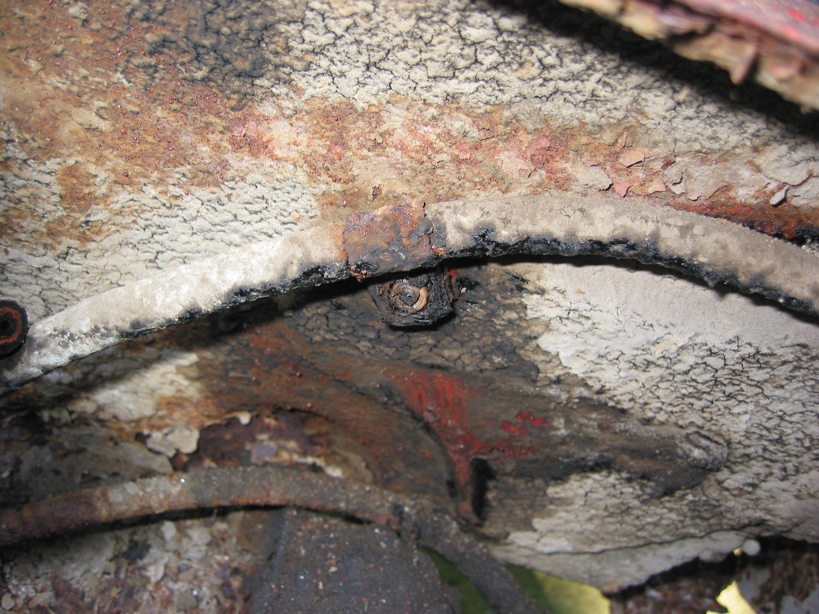
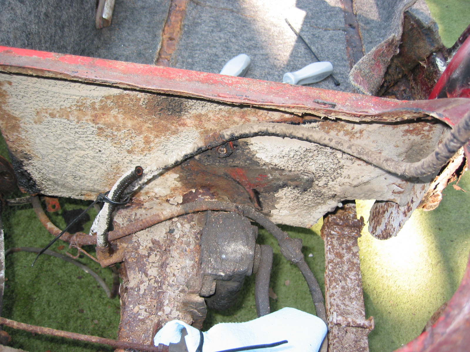
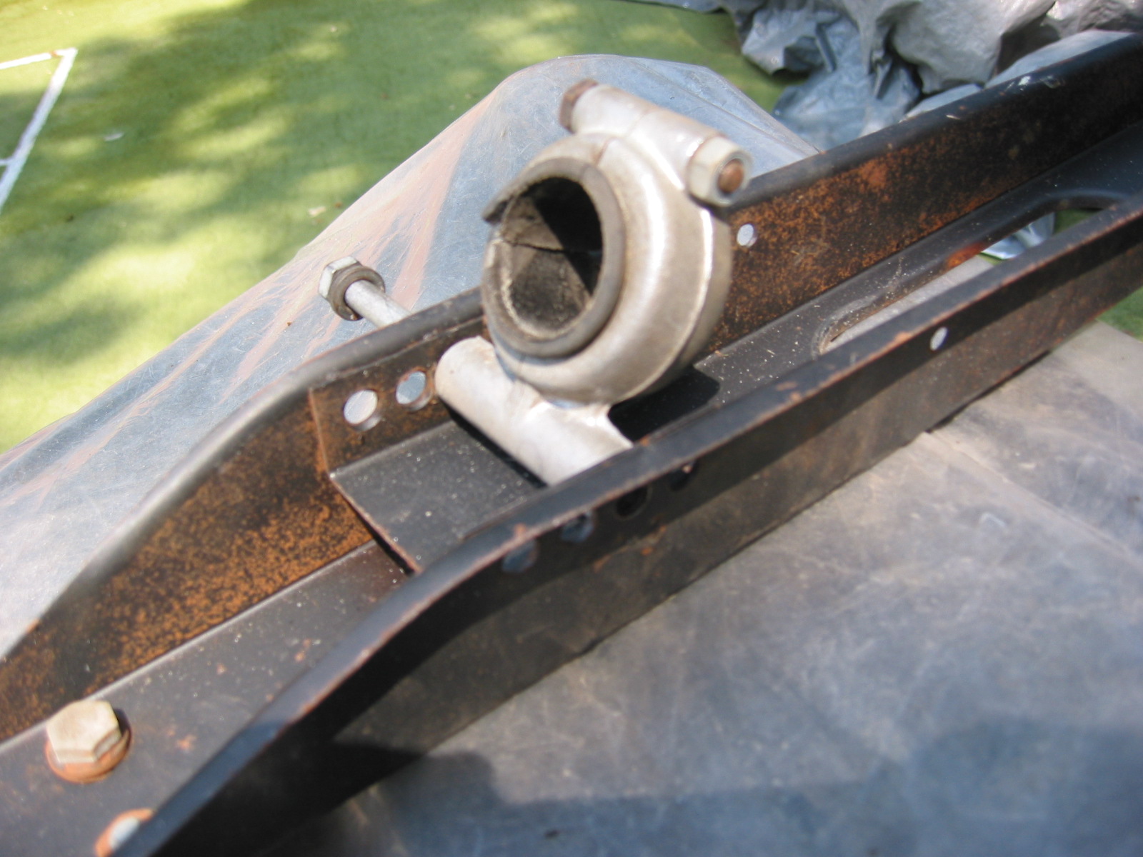
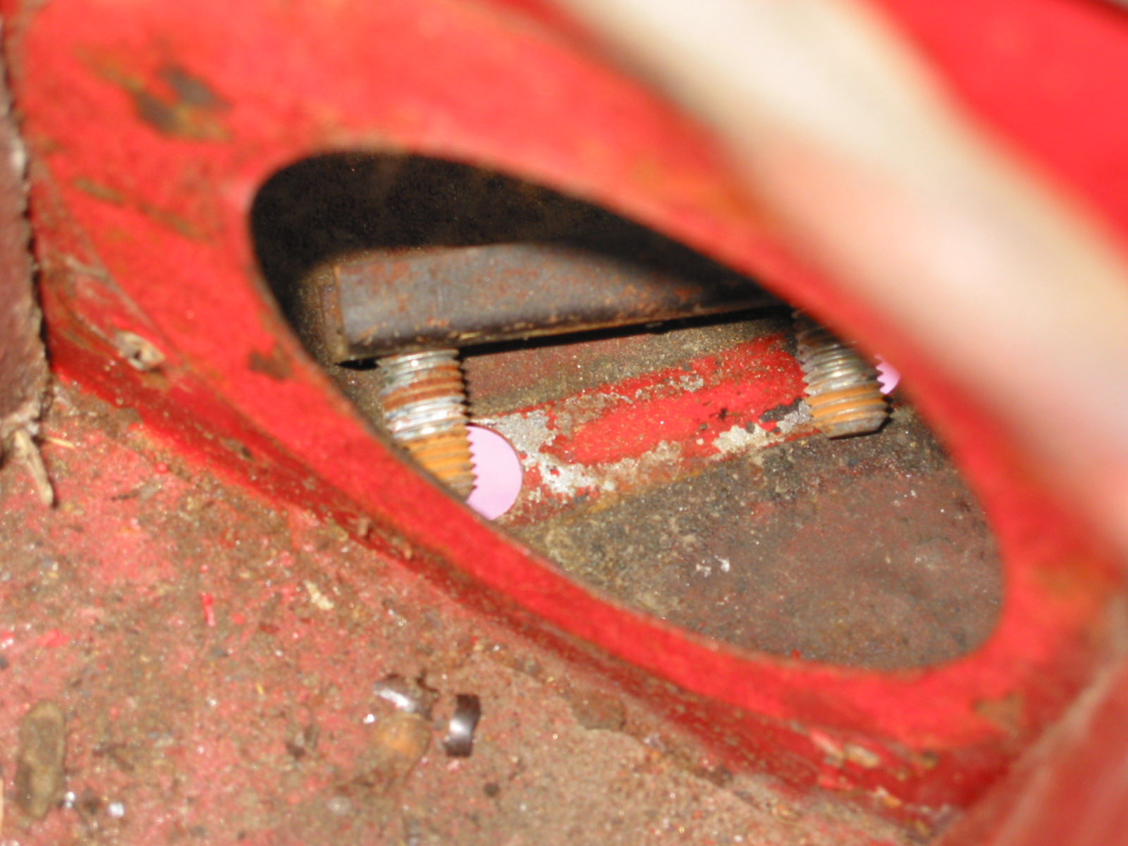
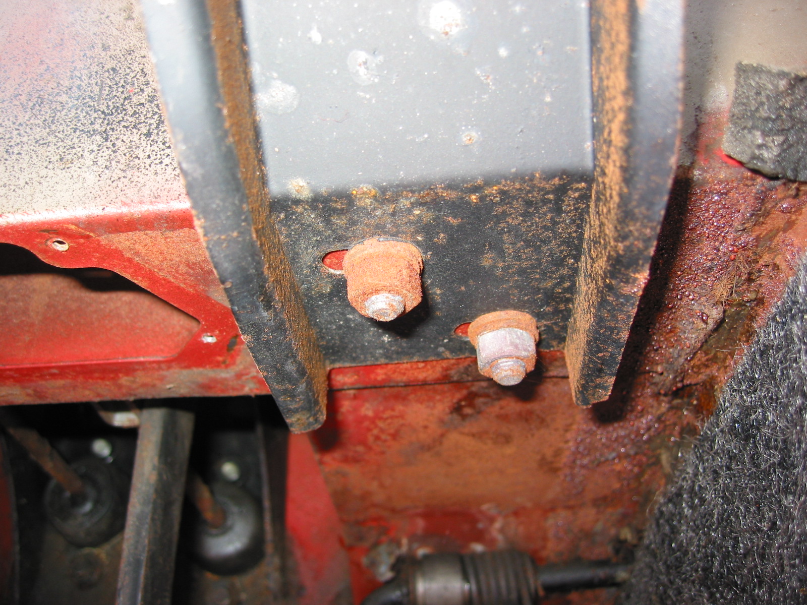
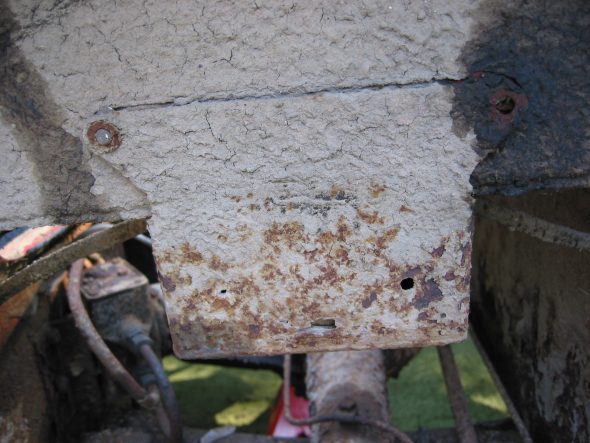
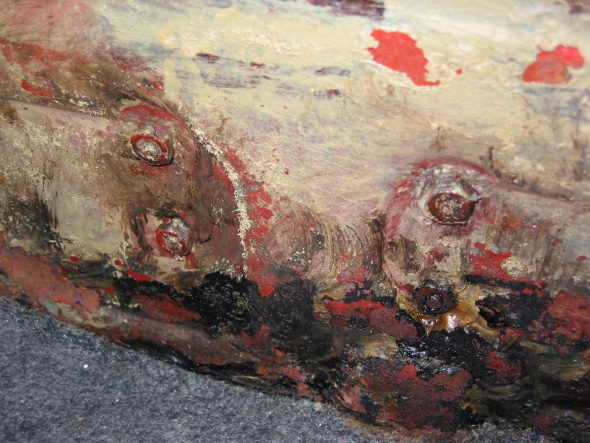
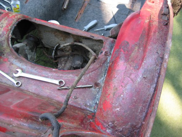
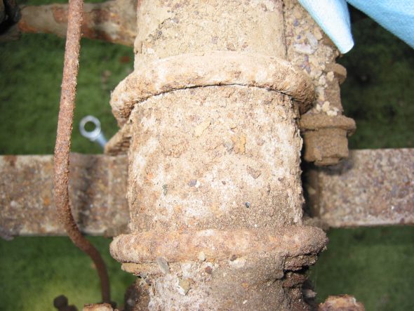
The Bump Stop Boxes – were removed from both sides of the car. Two large pozi-drive screws with large washers and nuts located by the rear occasional seats hold the boxes. Two bolts and nuts must also be removed in the side of each box that secure clamps for wiring. In our case the bolts were all broken from wear and tear.
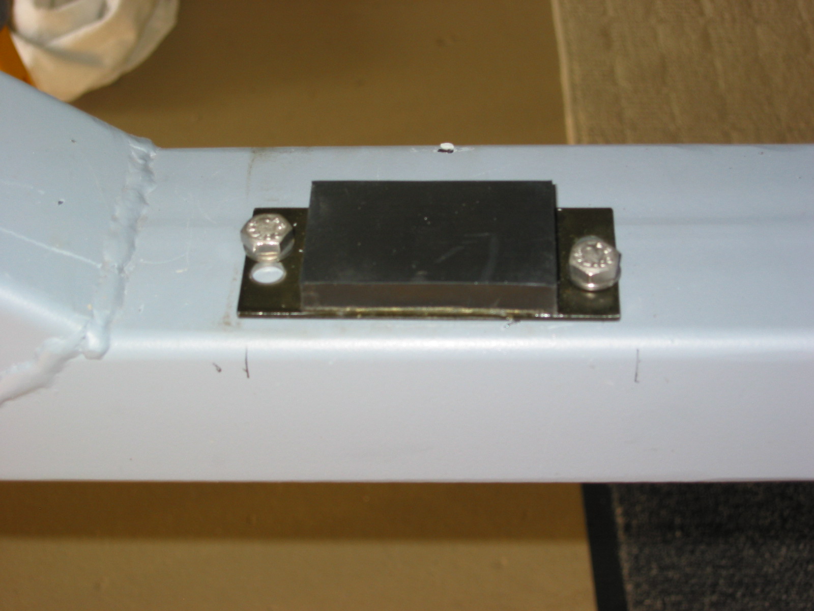
Rear Axle Bump Stop on Car
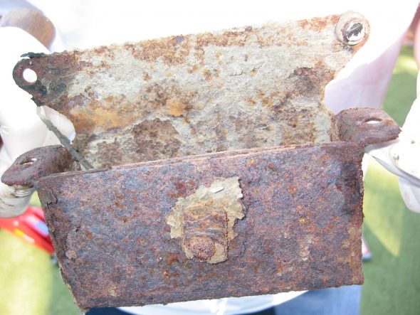
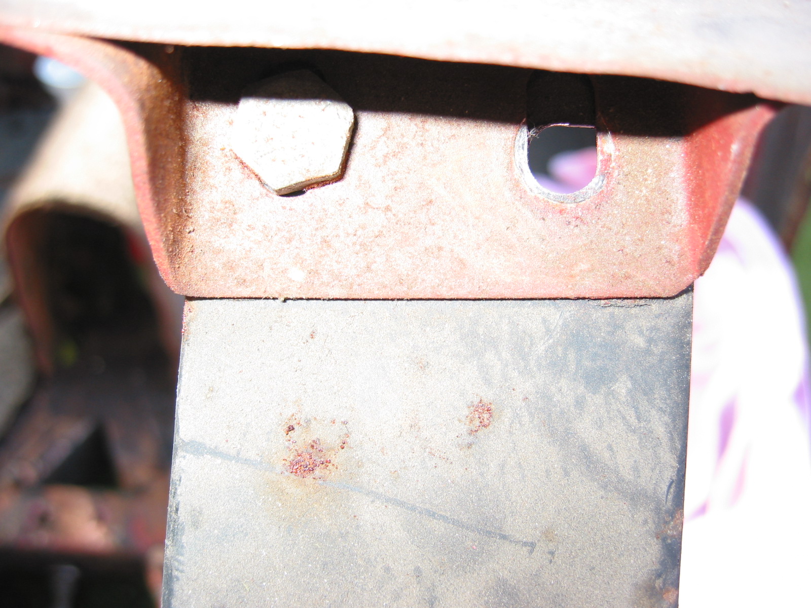
Rear Axle Bump Stop Removed

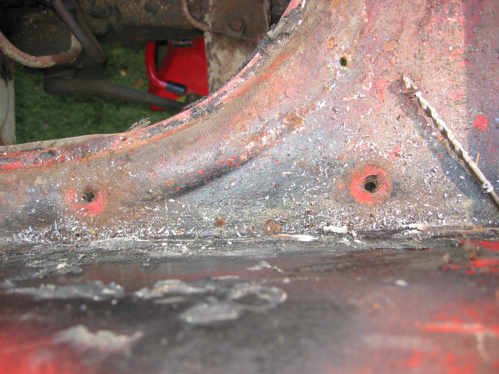
Mounting Holes
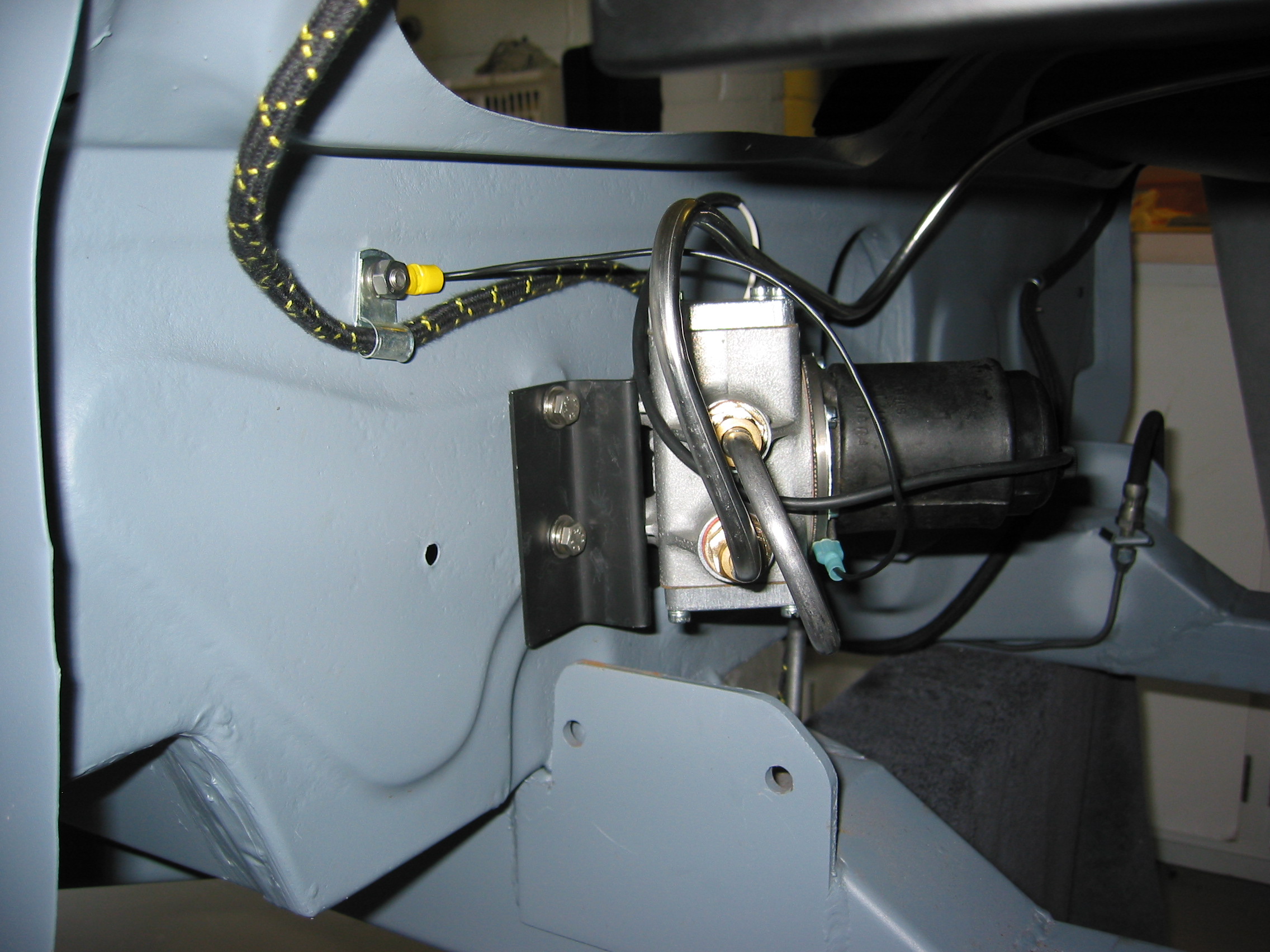
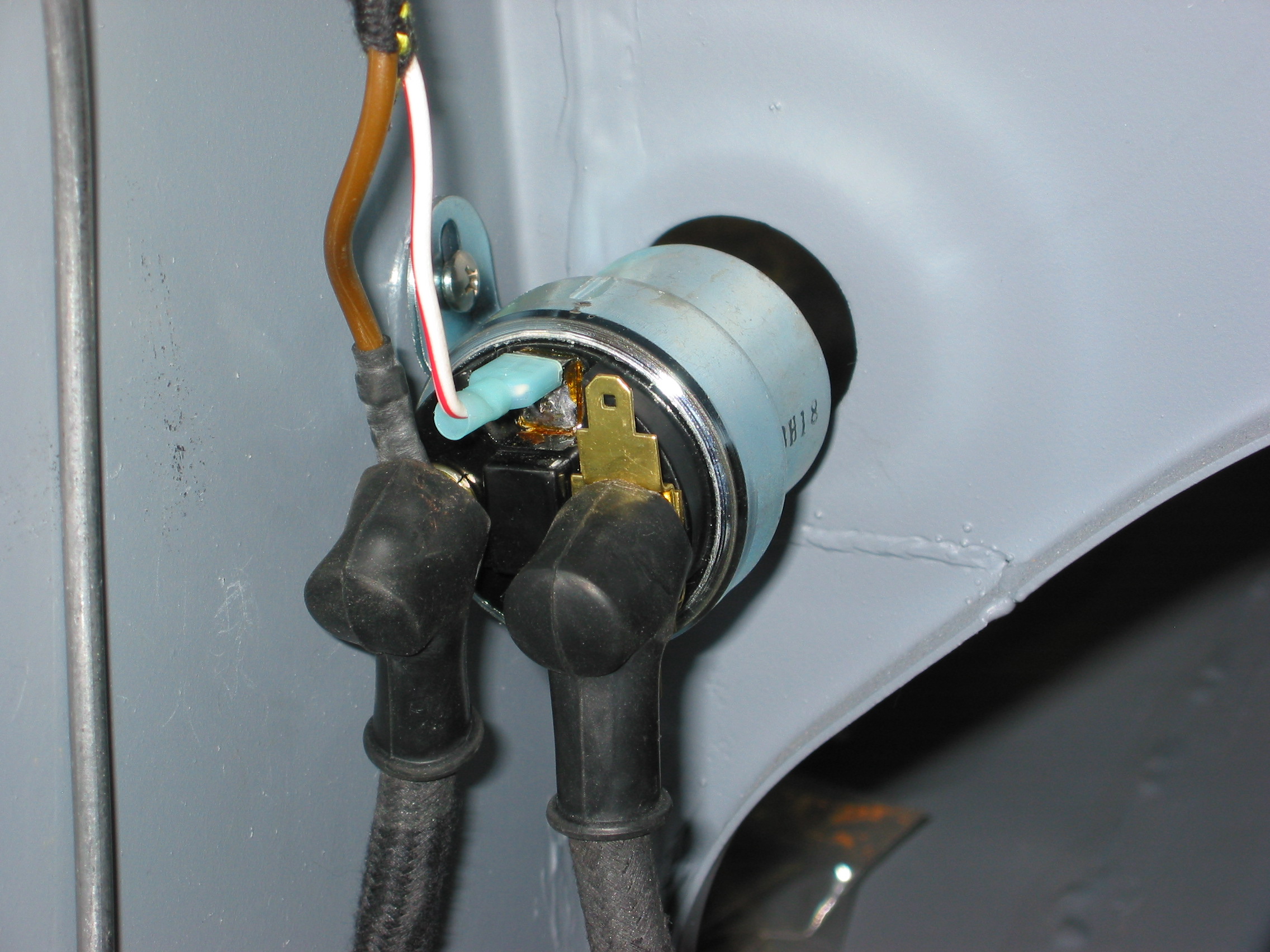
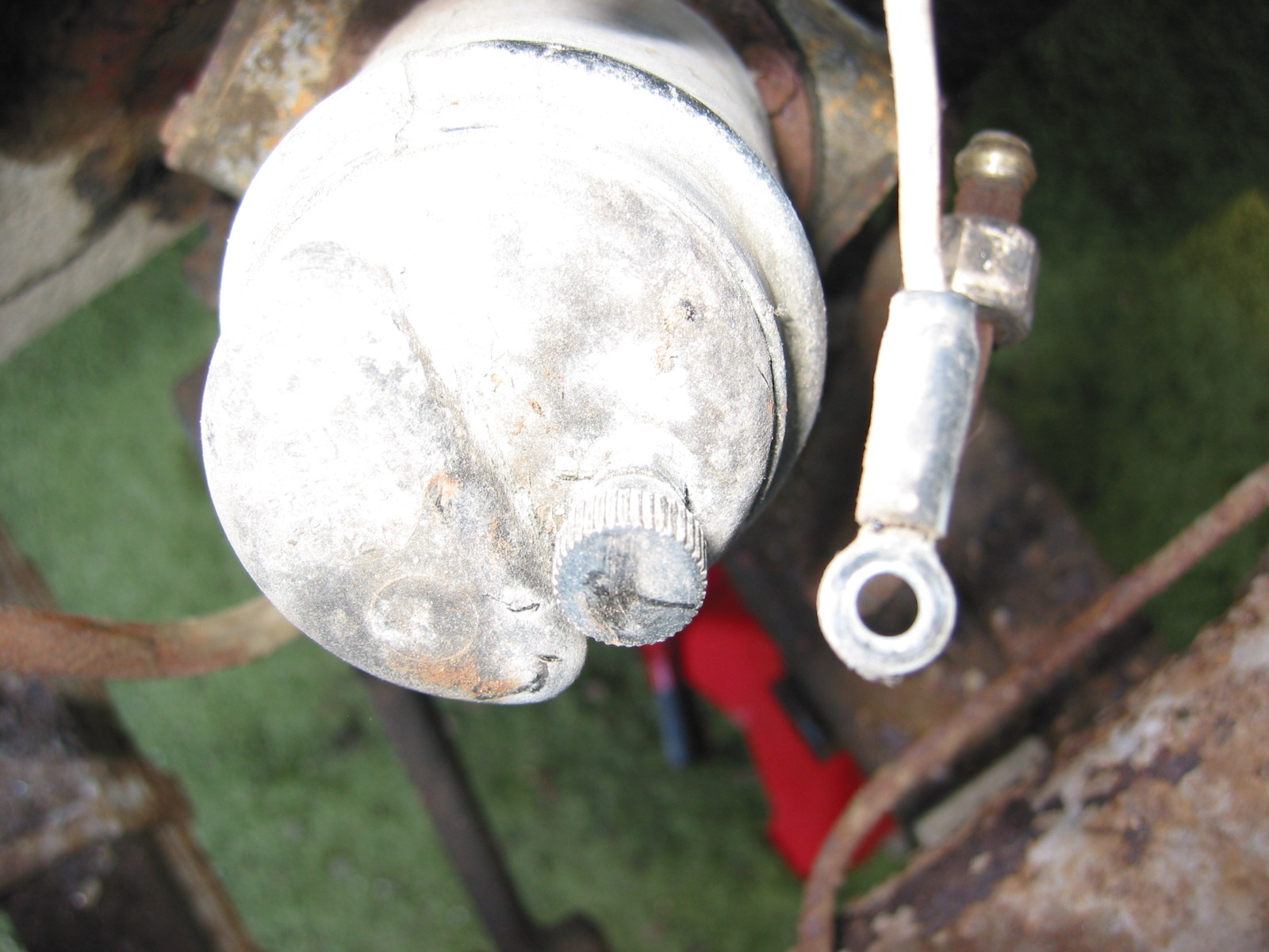
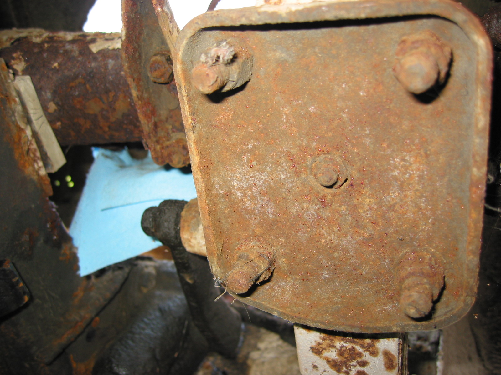
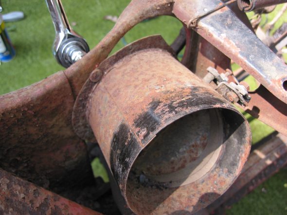
The Fuel Pump – was removed to get it out of the way of the axle. Disconnected 5/8” in and out fuel pipes to the pump. Remove 4 7/16” bolts into fixed nuts on the rear bulkhead wall. Finally, disconnected wire at knurled fixing knob.
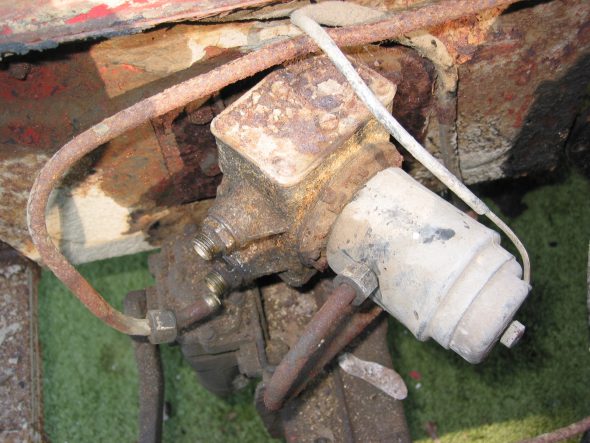
Fuel Pump Mounted to Bracket at Rear Kick Panel

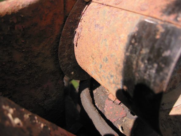
Disconnected White Wire to Fuel Pump
Fuel Pump and Bracket Removed
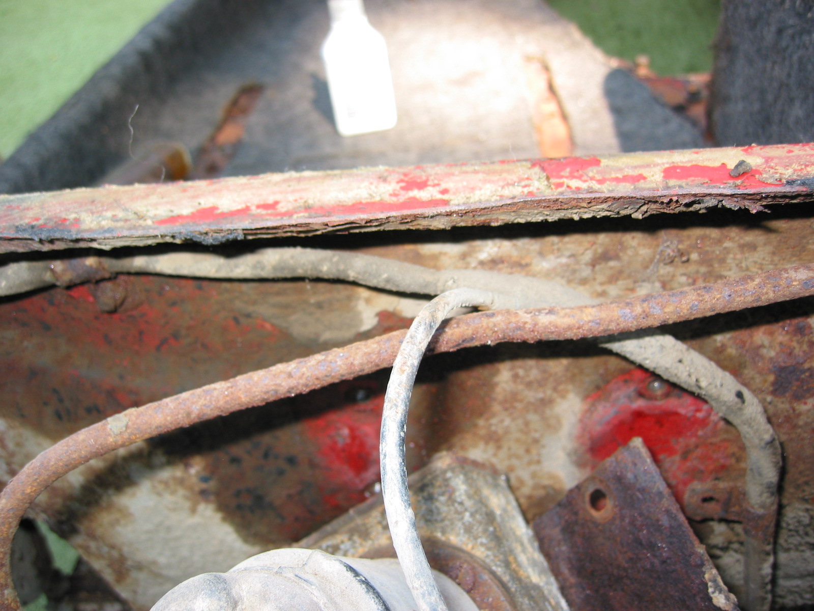
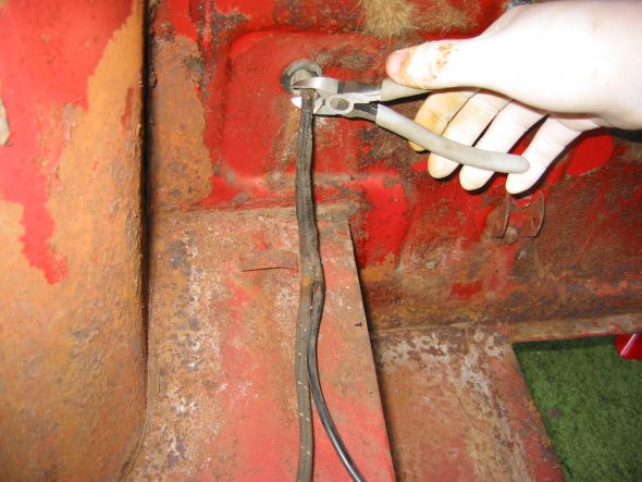
Boot wiring harness extension – Wiring goes to the fuel sender and lights. We clipped the wire at the bulkhead for easy removal since we knew we would be replacing it. Two clamps with split head screws secure the wiring through the bulkhead wall. Additional connections are then made to route to the tailights.

Fuel Pipe to Pump and Wiring Harness
Wiiring Harness to Boot
Wiring Connector for Lights in Boot

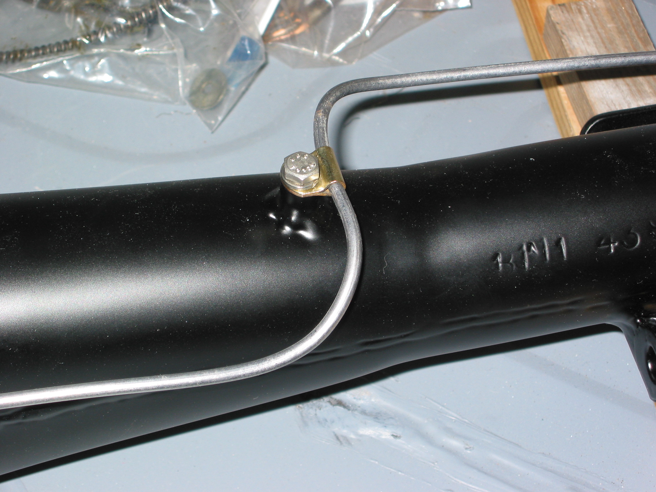
Wiring Clip

Wiring and Handbrake Cable
Wiring Cable Removal
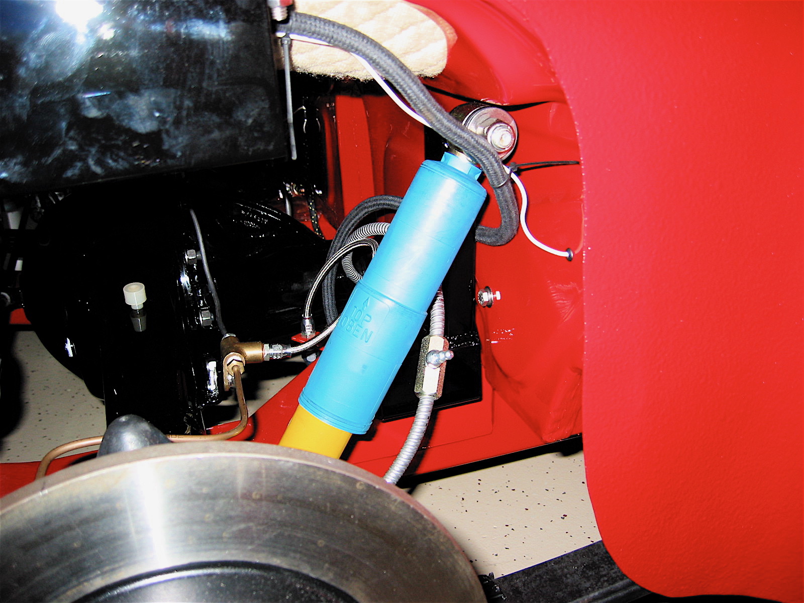
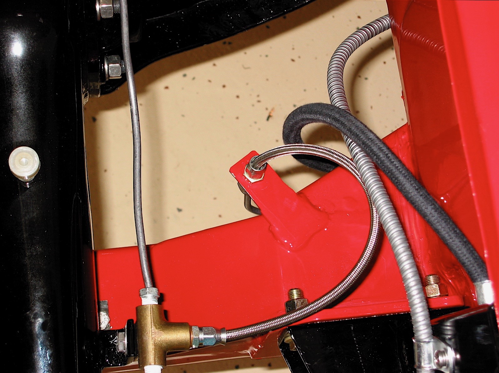
Handbrake cable – The cable was removed from its axle attachment. To save time we just cut the flexible brake line hose to the junction.
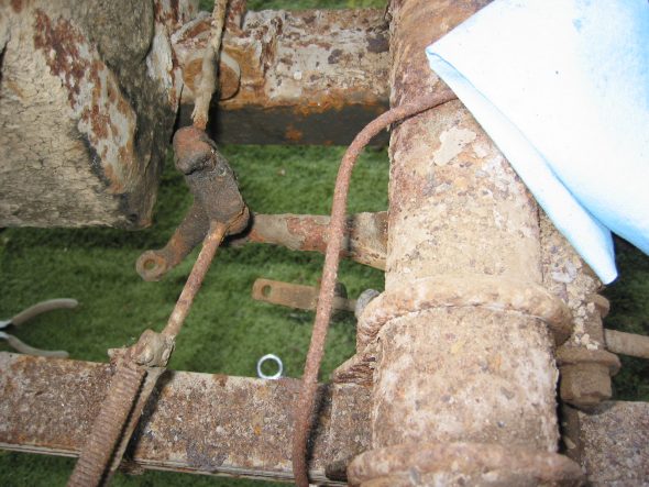
Handbrake Components
Handbrake Components at Rear Axle
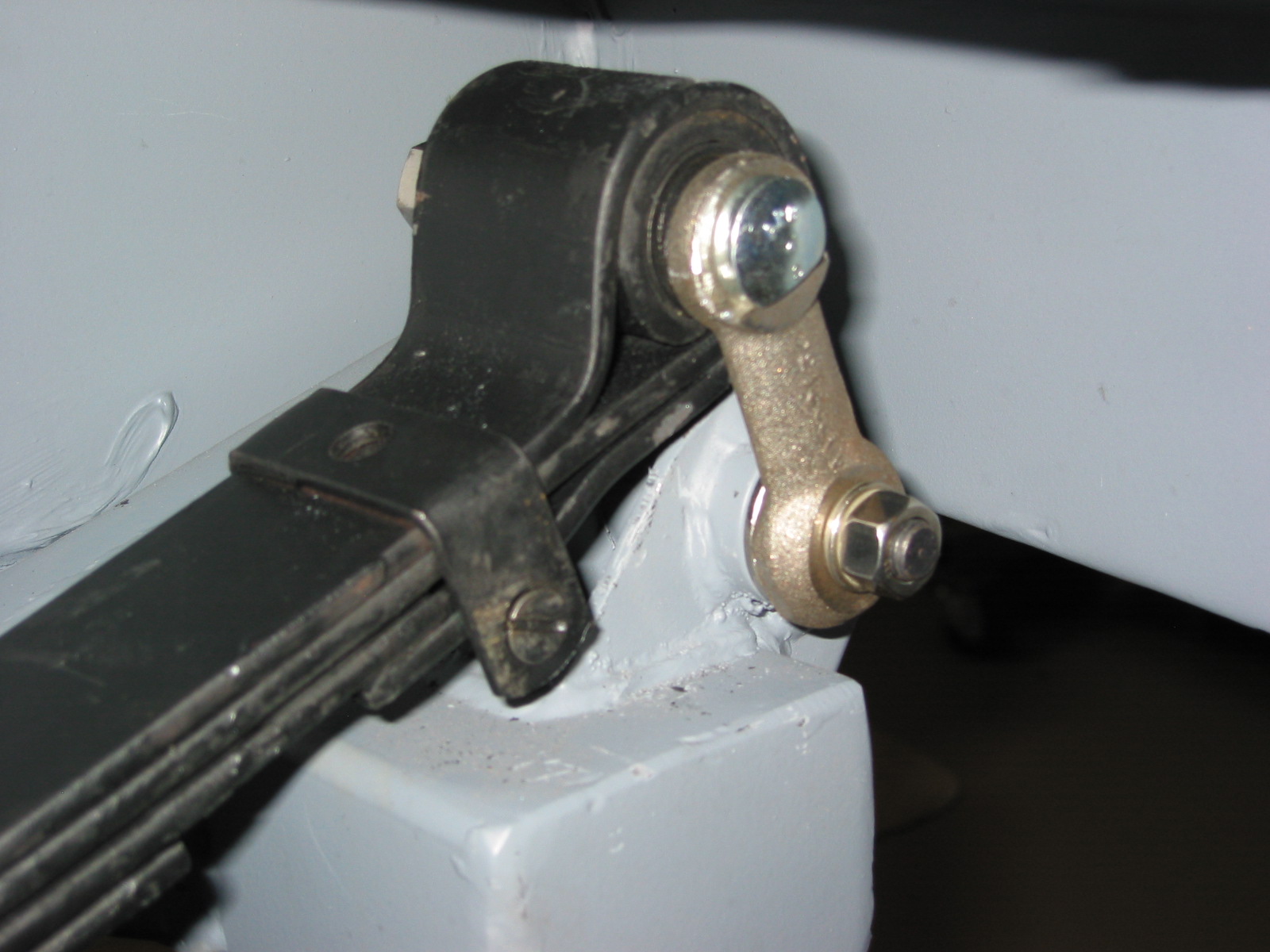
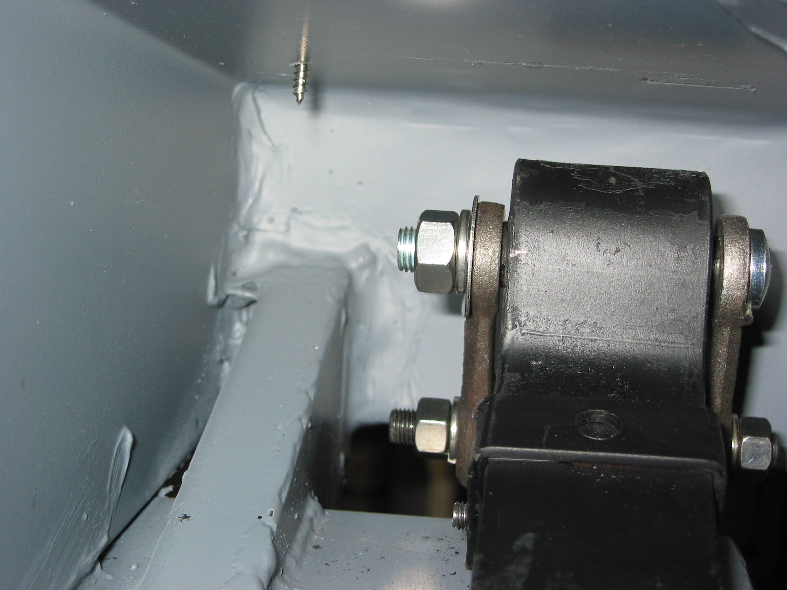
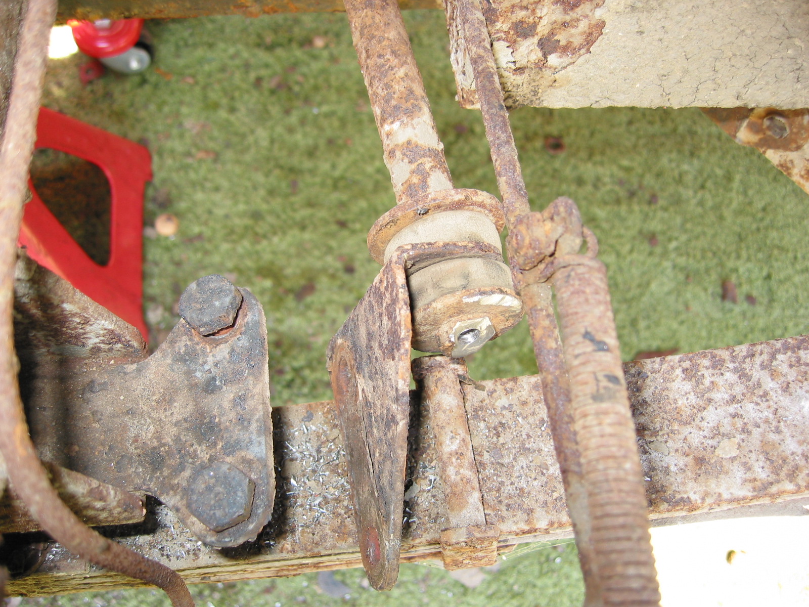
Rear Shock Absorbers – First removed nut to axle link. Then removed two nuts and bolts to rear bulkhead for each.
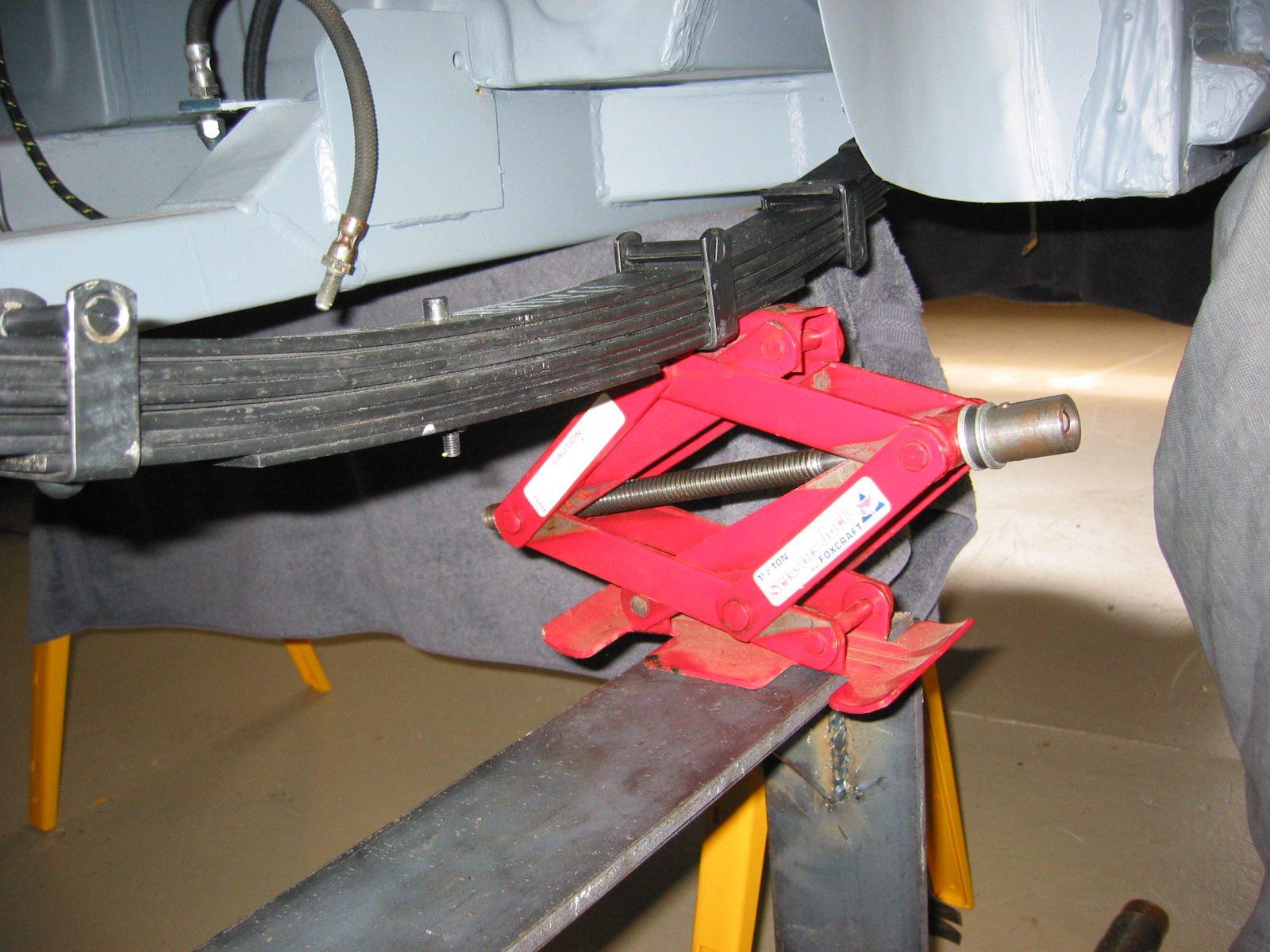
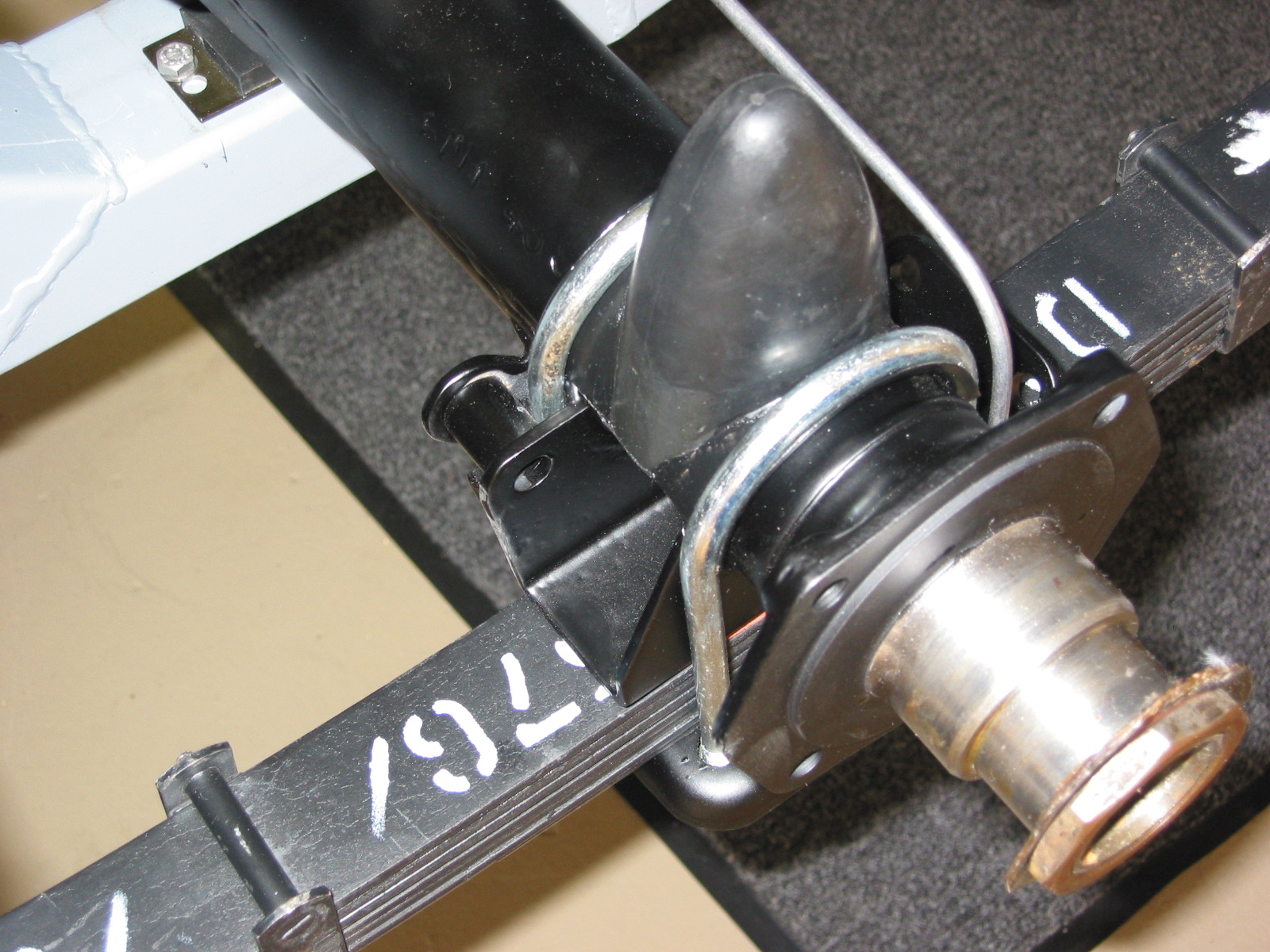
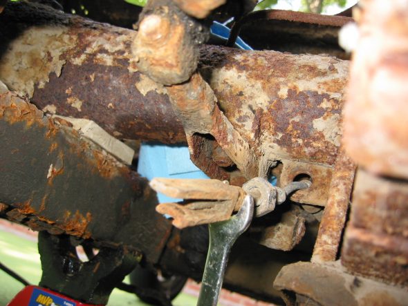
Rear Axle – Drain differential fluid from the rear end. Place jack under differential to take pressure off springs. Loosen the four nuts on the U bolts under the mounting bracket. The nuts should be loosened gradually to avoid too much pressure on the spring. Disconnect tramp bar at mounting bracket on axle. Rotate axle and lift and slide out to the right.
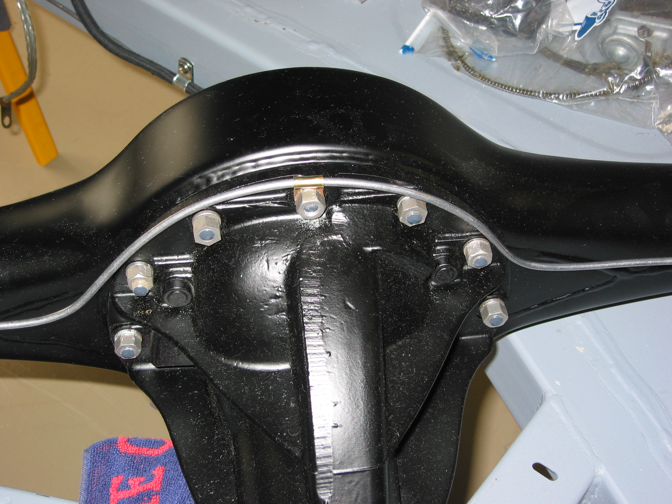
Rear Axle U Bolts

Rear Axle U Bolt Mounting Plates
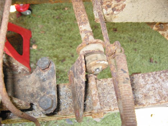
Panhard Rod Mounting
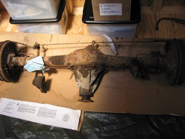
Rear Axle Removed
August 4, 2002
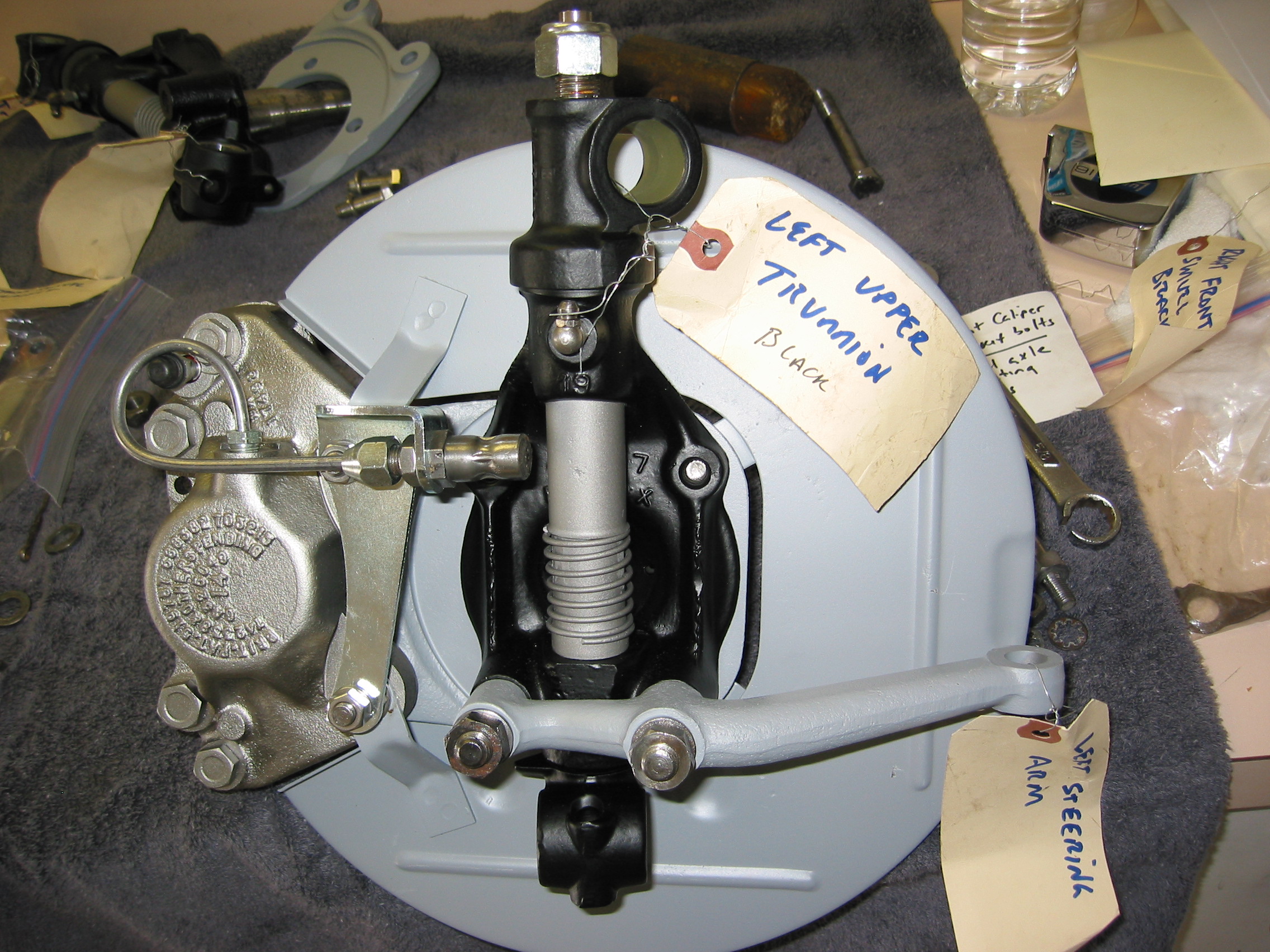
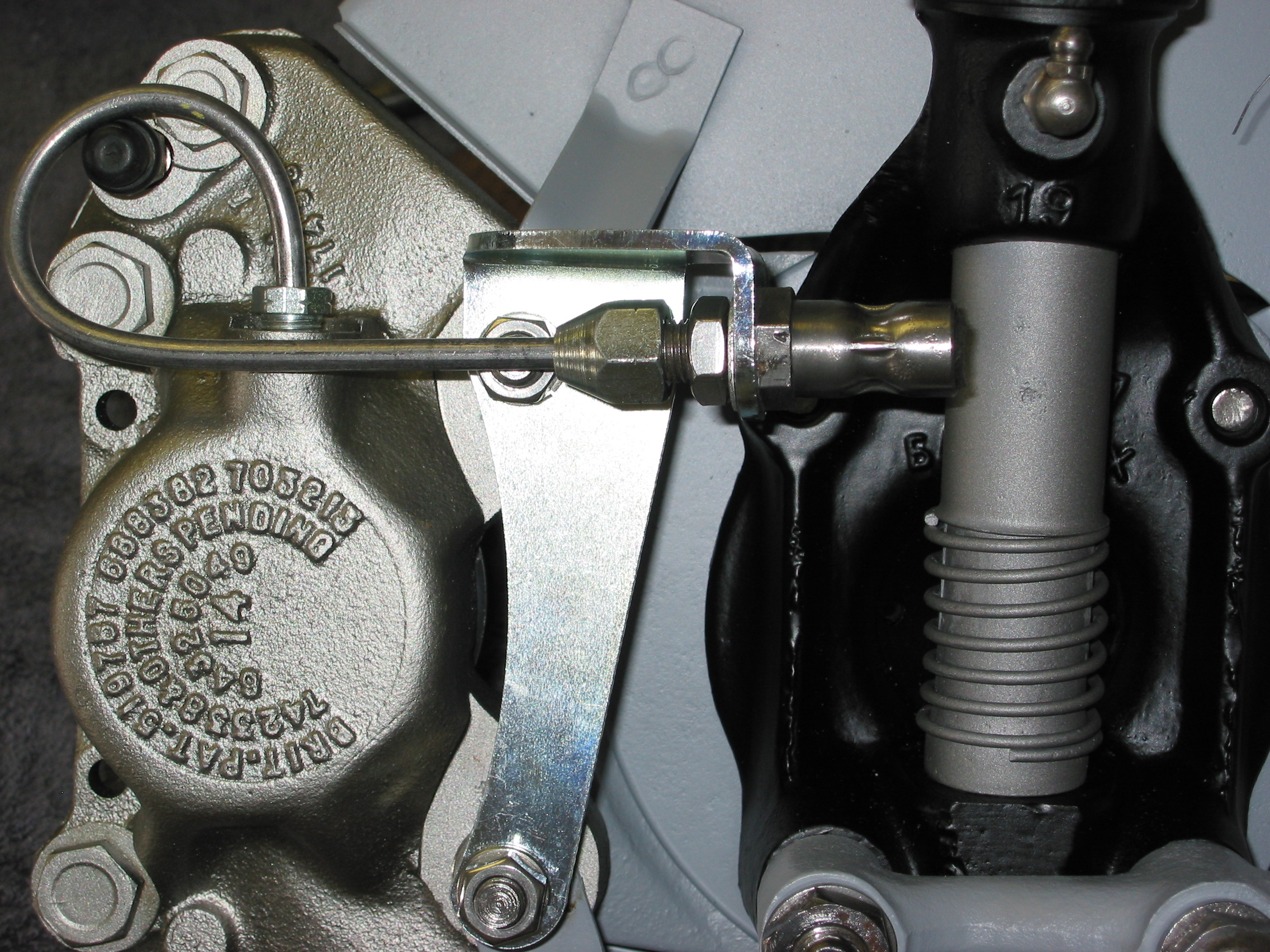
Steering Assembly
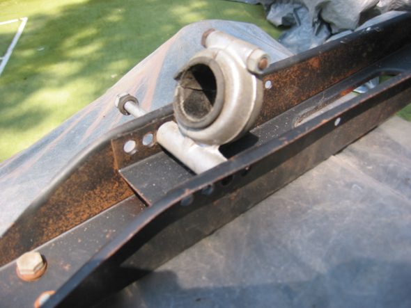
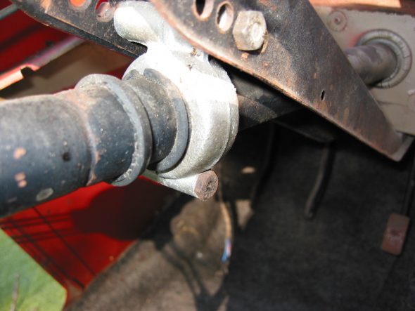
Steering Column Support Clamp – There are four holes available for the bolt and nut on the steering column bracket. The bolt was found in the 2nd hole from the firewall. Bolt heads were to the right, nut to the left.
Steering Column Mount

Steering Column Bracket Mount
Steering column bracket – Removed the bracket by loosening four bolts and nuts.
Steering Column Bracket Removed
Steering Column Rubber gasket

Steering Shaft Bracket to Frame Mount from below

Steering Shaft Bracket to Frame Mount from Above