
Door Handles and Locks
Keyless Entry or Remote Control Door Locks
I am installing a keyless entry system with central locking activated either by the front door handles (exterior or interior) or by a battery operated key fob. Details regarding the system may be found in the “Remote Control Door Locks” post in my web site: https://valvechatter.com/?p=9205.
This post will include the mechanical components of the door locking system. This image from the MK2 Service Manual provides a nice schematic of he parts used in the locking system:
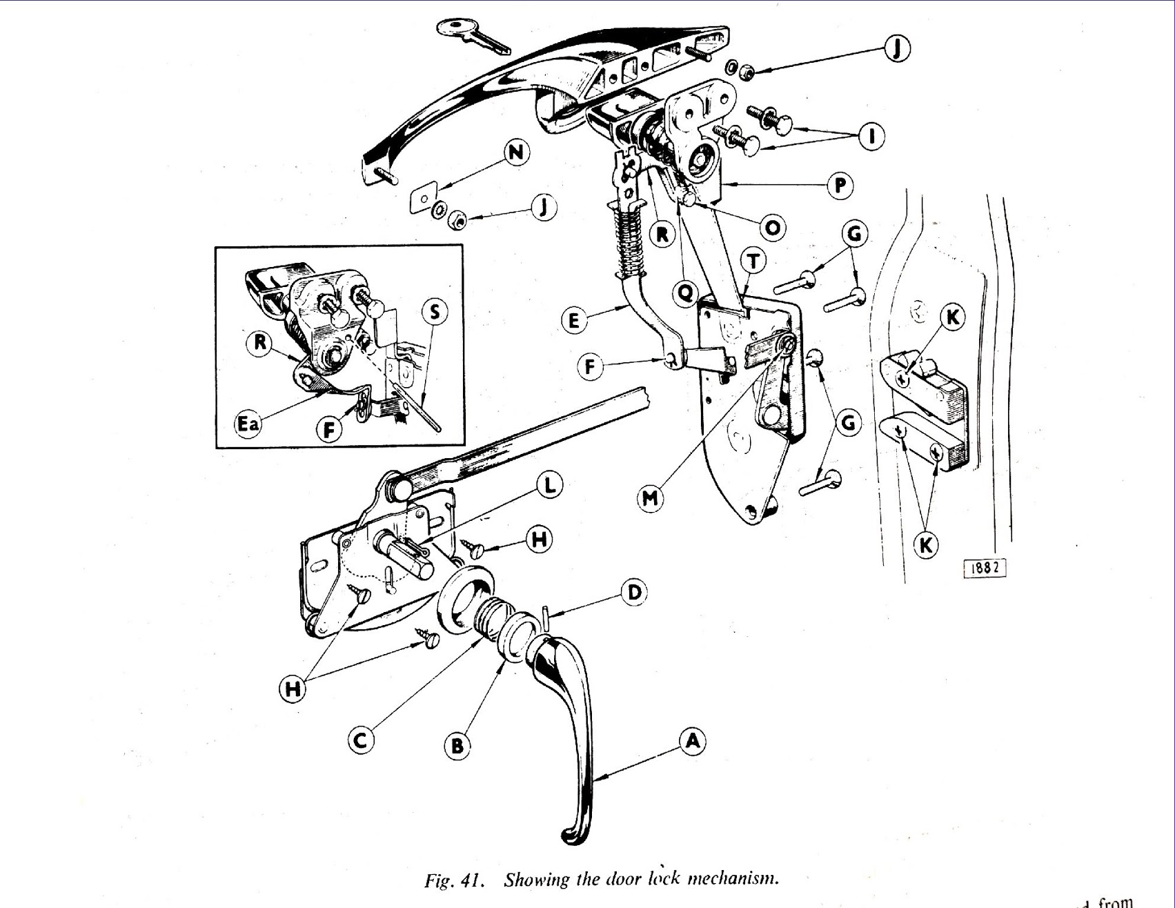
MK2 Door Lock Mechanism
Outside Door Handles
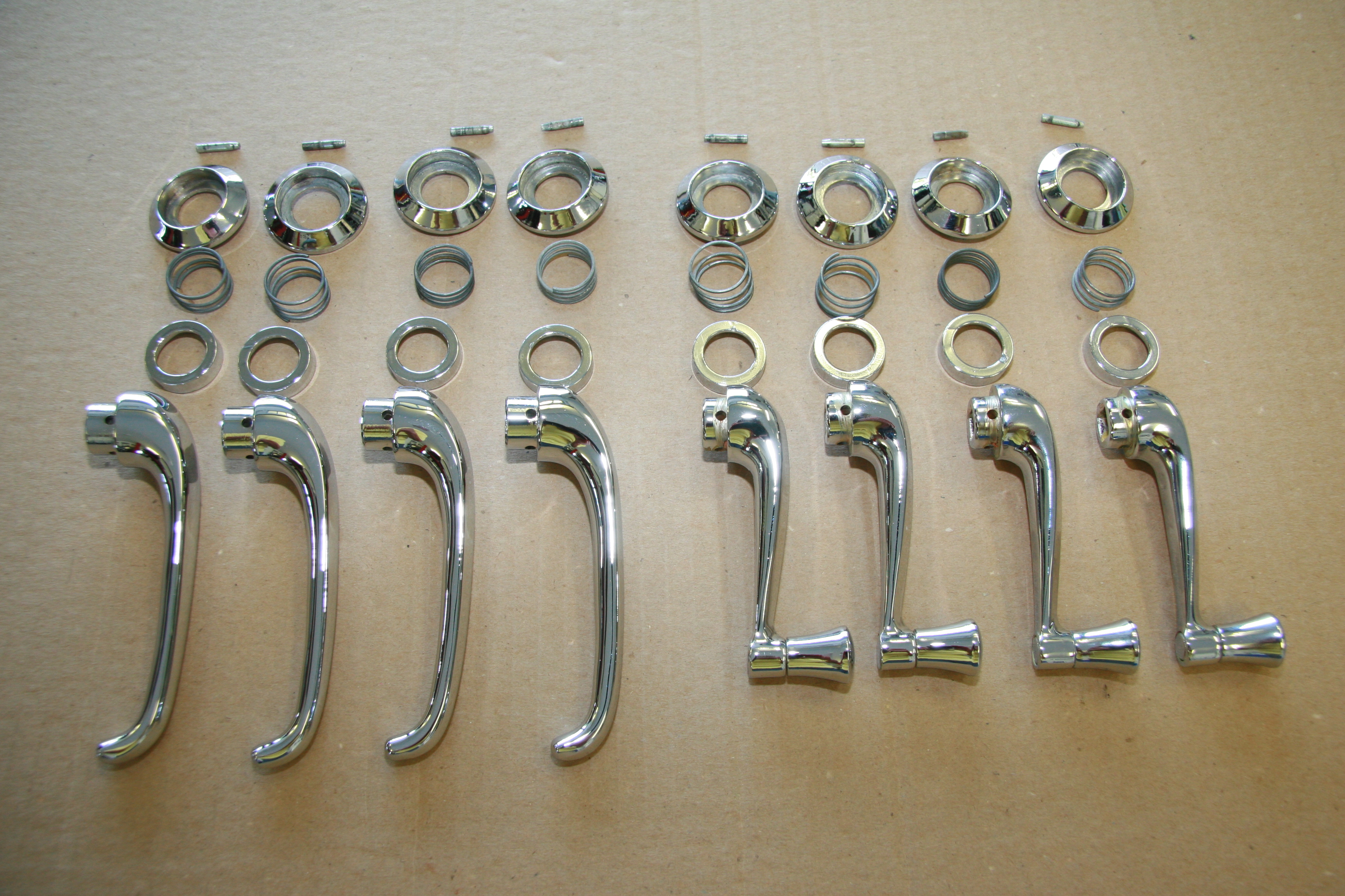
I am using the original outside door handles, but each was rechromed. I cleaned each of the operating lever assemblies and greased each push button shaft with white lithium grease.
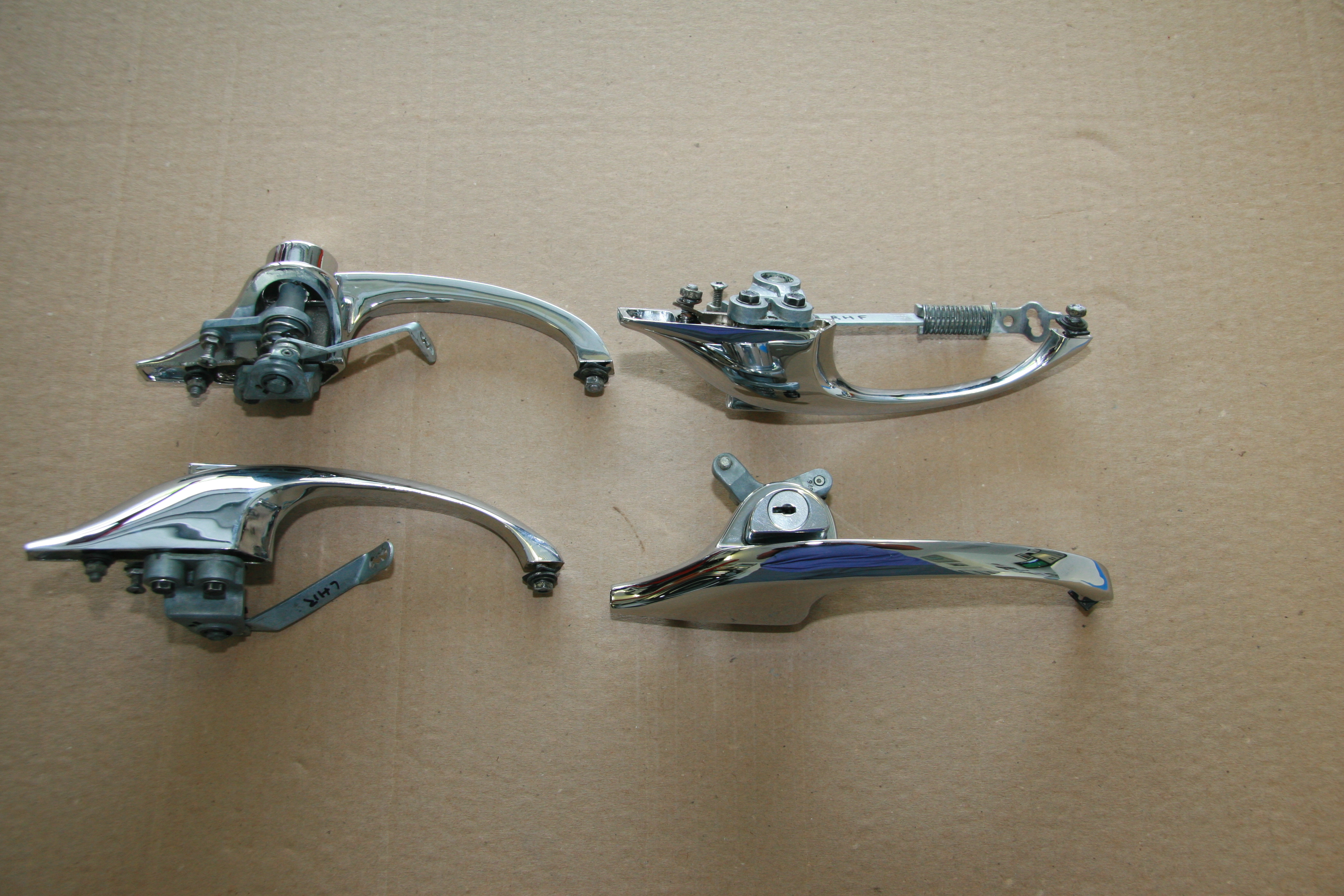
Outside Door Handles with Operating Lever Assemblies
Door Handle Lock Cylinders
The face of one of the lock cylinders was mangled from use so I decided to replace both cylinders with new units from SNG Barratt. The Service Manual indicates that only oil should be used to lubricate the the private lock cylinders, and recommends once a month. Grease is never to be used.
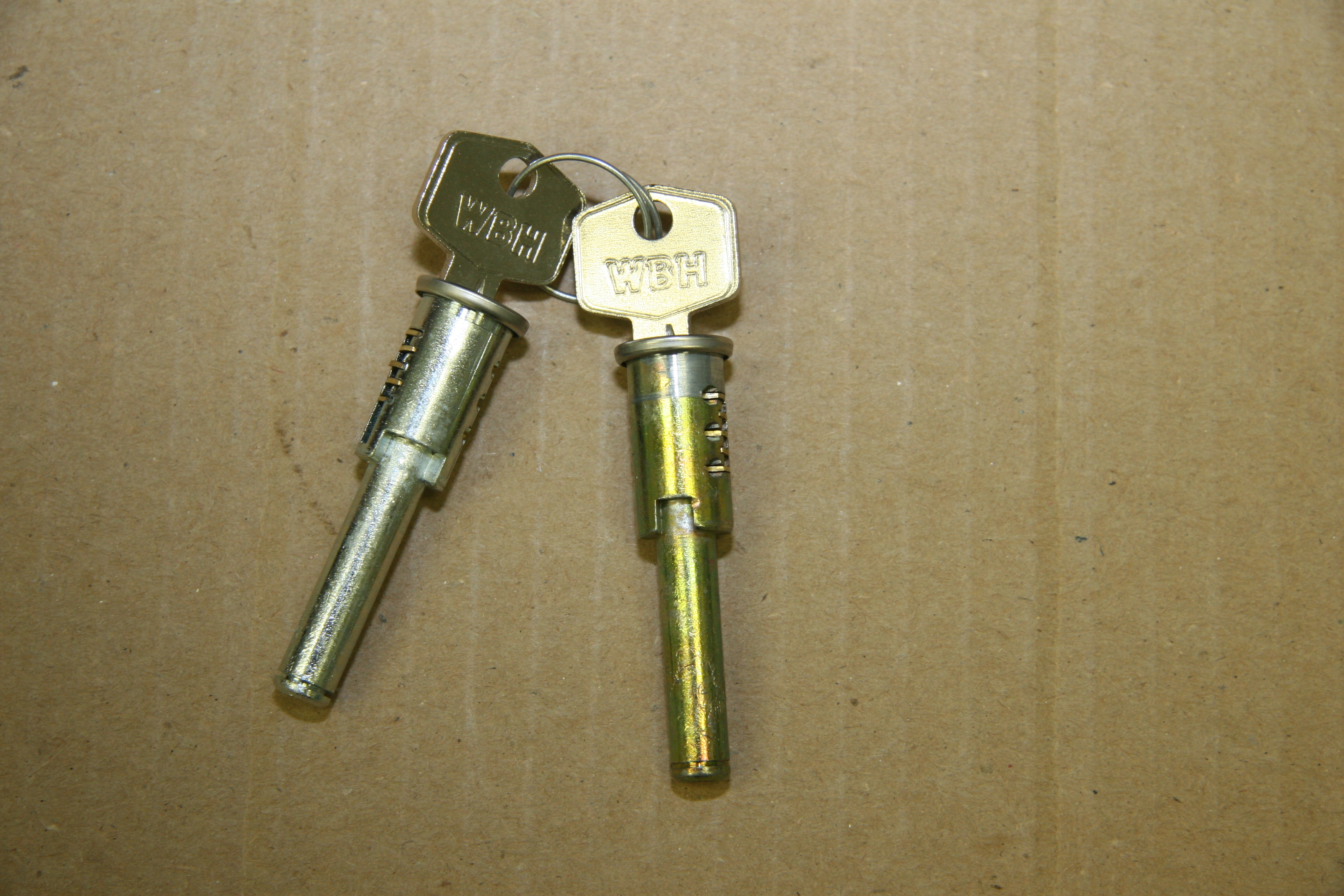
New Front Door Lock Cylinders and Keys
Lock Assemblies for Doors
I chose not to rechrome the lock assemblies, or lock cases as they are called in the Service Manual, primarily because they are not easy to take apart given that they are riveted together. While the chrome finish is not perfect on the locks, I think it will be good enough. I cleaned and lubricated each lock and polished the chrome. New chrome screws will be used. There is a small hole located at the top of each lock case (“T” in the schematic above) into which a few drops of thin machine oil should be introduced one a month.
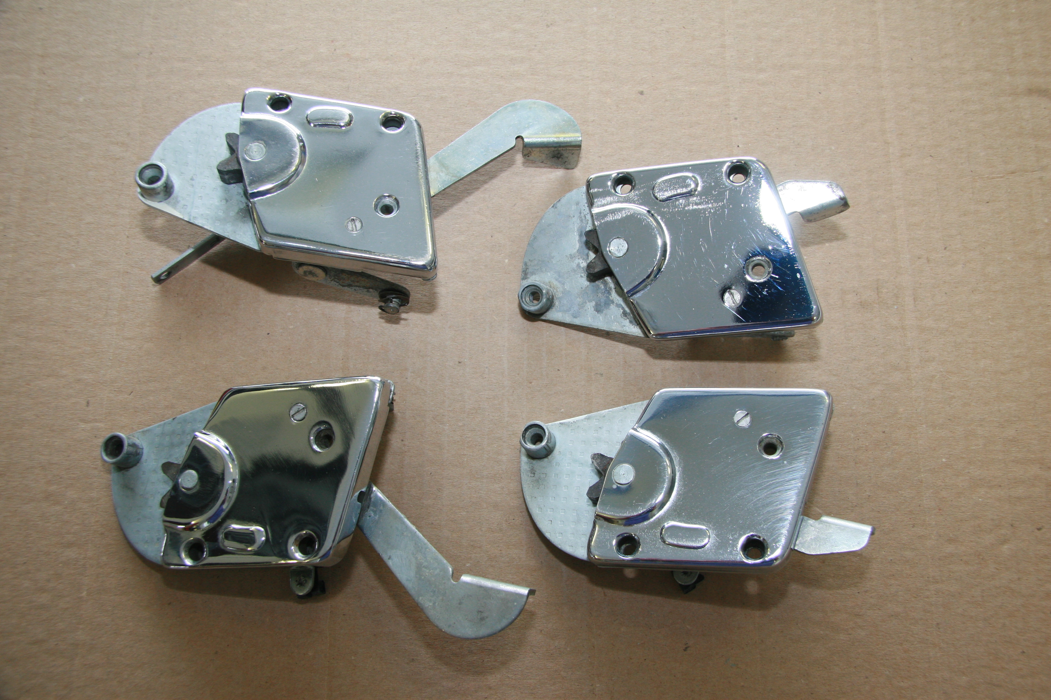
Lock Assemblies for Doors
Inside Door handles and Handles for Window Regulators
I am using the original inside door handles, but each was rechromed.
Inside Handles for Doors and Window Regulator Handles Rechromed
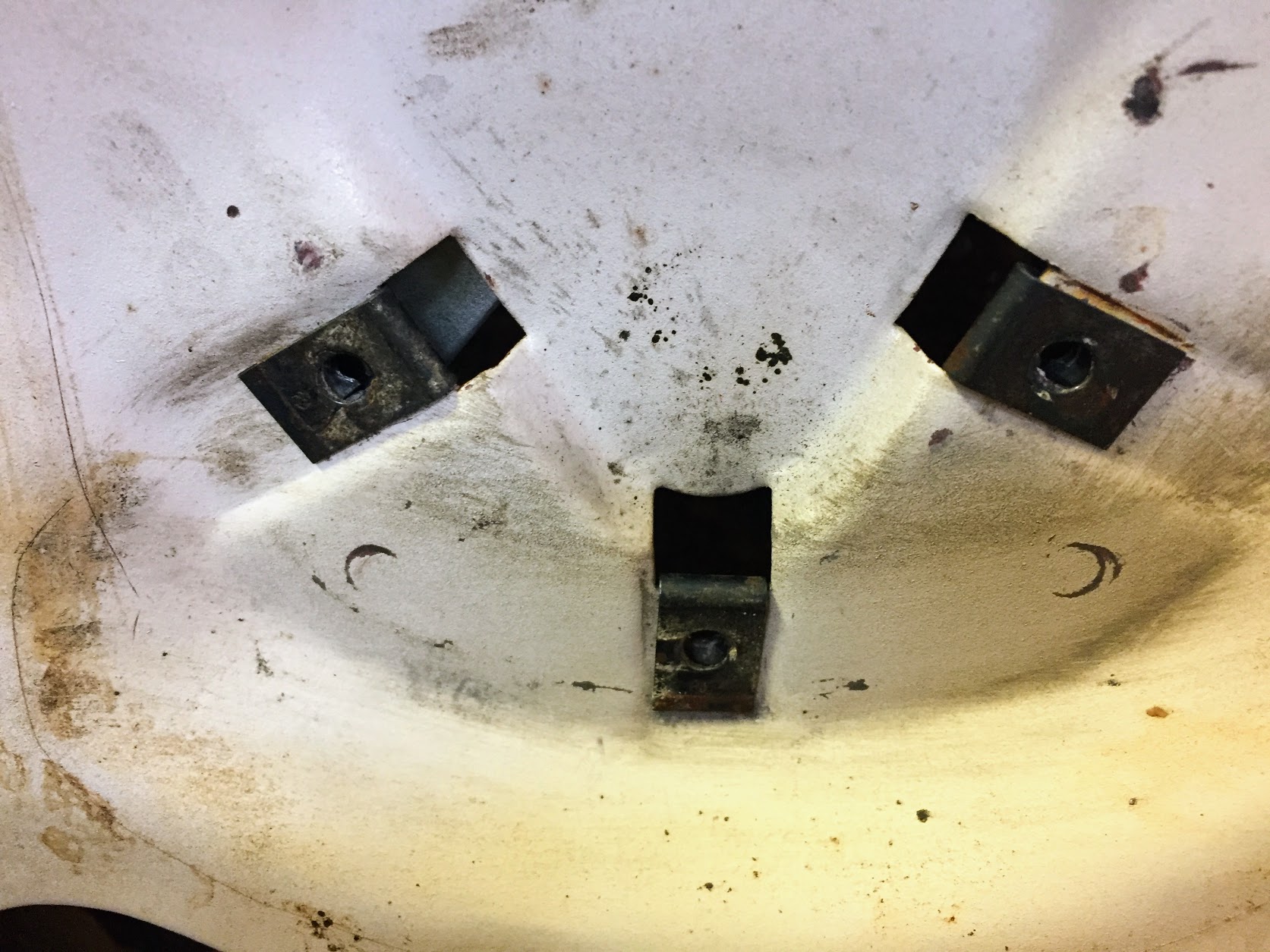
Door Lock Strikers
As with the locks, I choose not to rechrome the strikers. I cleaned and polished each. Each striker had a shim. The shims were cleaned and cad plated. New chrome screws will be used. Each Striker is mounted to the door with three chrome pozi-drive oval head 1/4″x28 x 1-1/4″ screws.

Strikers for Door Locks
Locking Mechanism Installation
First, all four exterior door handles are installed on the doors. Each handle has two #10-32 mounting studs with a flat washer, shakeproof washer and nut. The front of the handles had what appeared to be leather or fiber pads between the handle and the door when I removed them from the car. I replaced these with neoprene pads that I cut to shape. Once finally mounted, these can be cut to shape with a sharp razor knife.
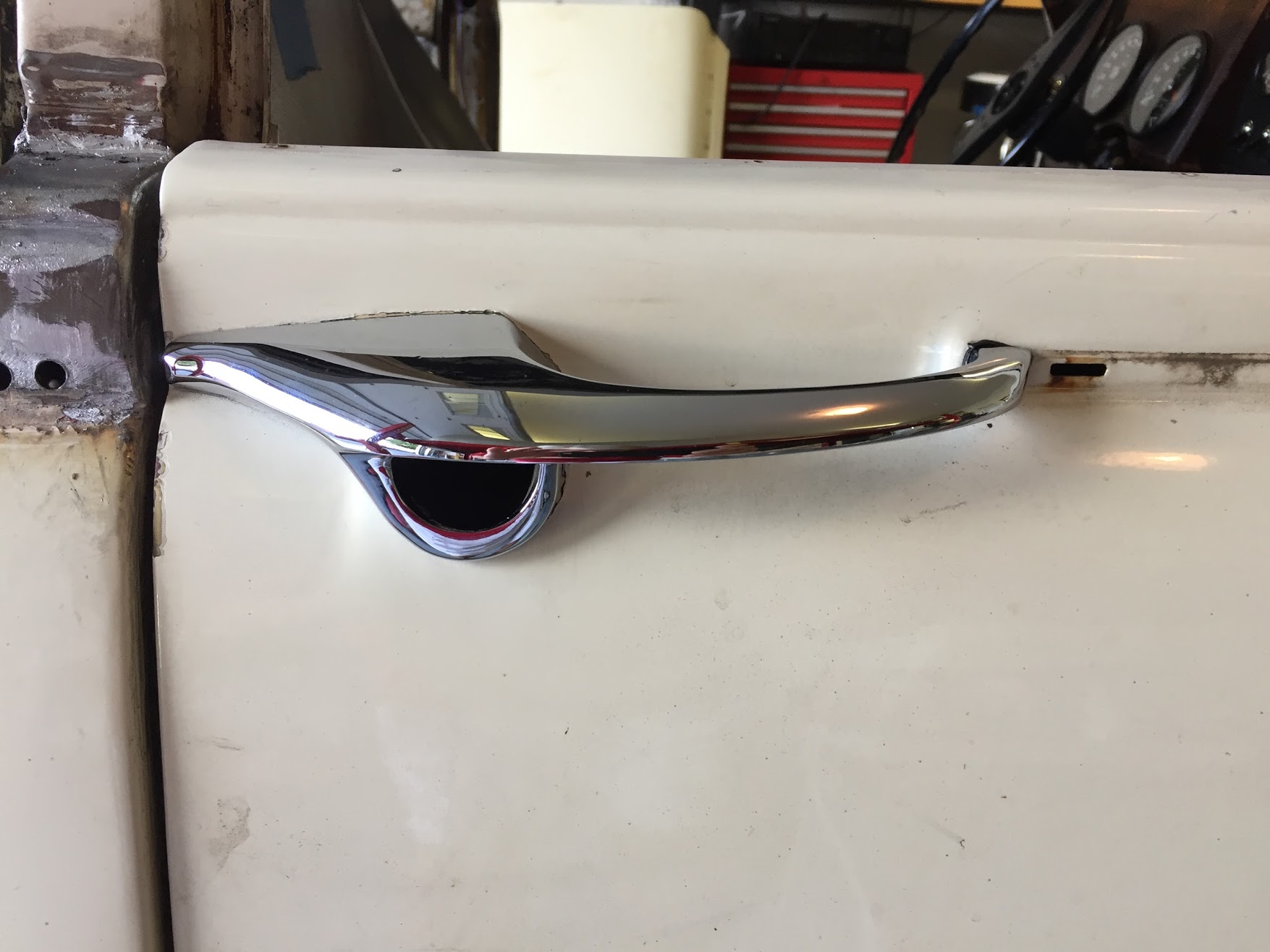
Exterior Door handle with Neoprene Cushion
Then the base plate assemblies are attached to the handles. These assemblies are marked LH and RH. As explained in my “Remote Control Door Locks” post referenced earlier, the Connecting Links for each door lock are modified for the operation of my keyless entry system modification. I will not explain further in this post.
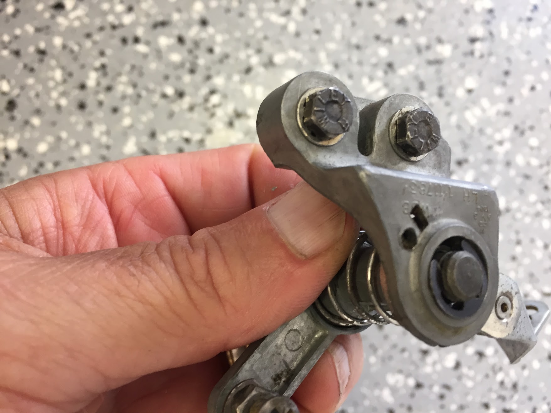
LH Lock Base-Plate Assembly
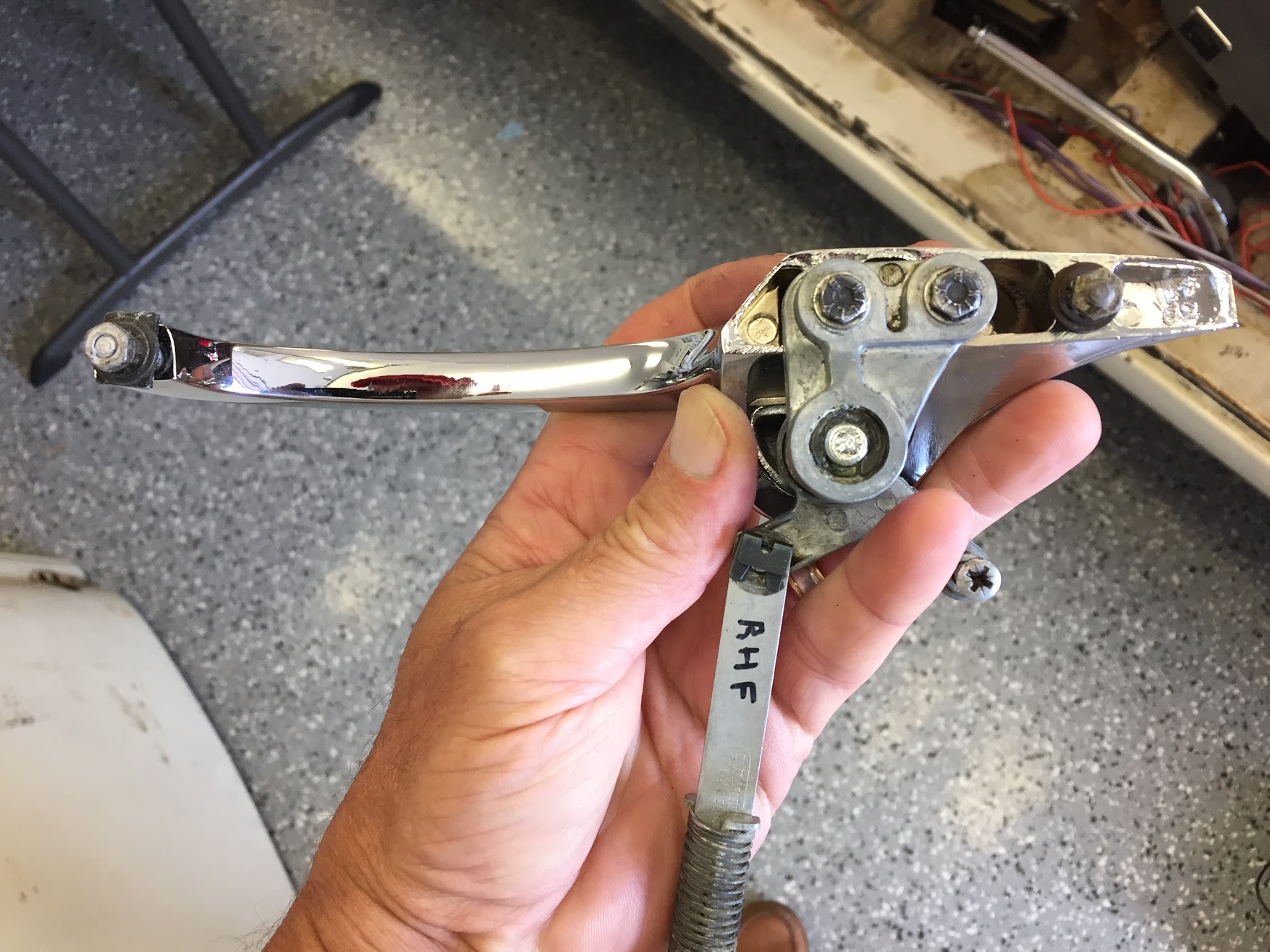
RH Lock Base Plate Assembly Orientation on the Door Handle
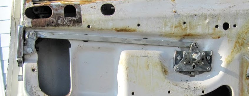
In the poor photo below, the Base-Plate Assembly can be seen and its two #10-32 x 1″ mounting screws can accessed through the door aperture. These two screws attach the Assembly to the exterior door handle.
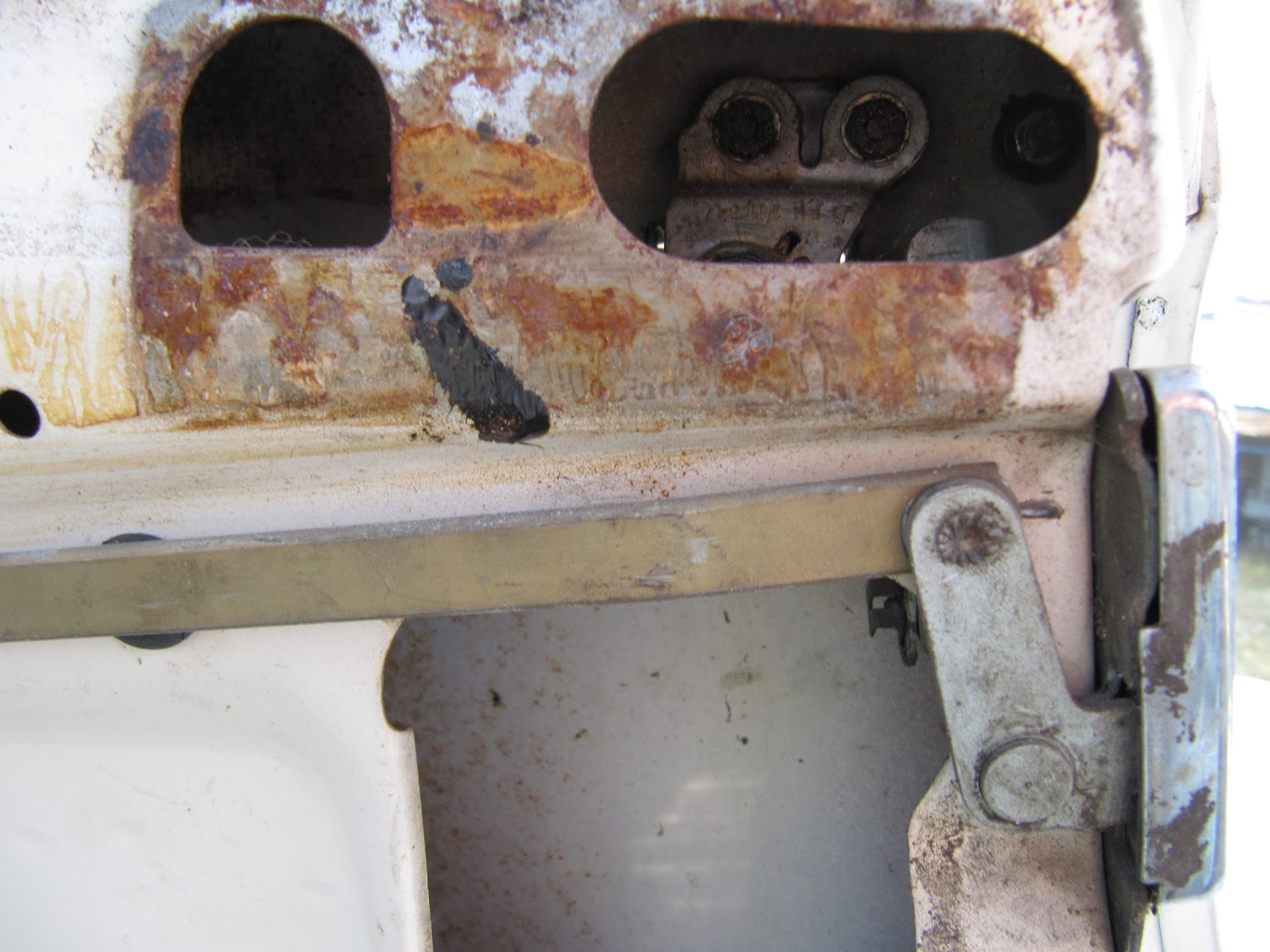
Door Lock Base Plate Assembly Viewed Through Aperture
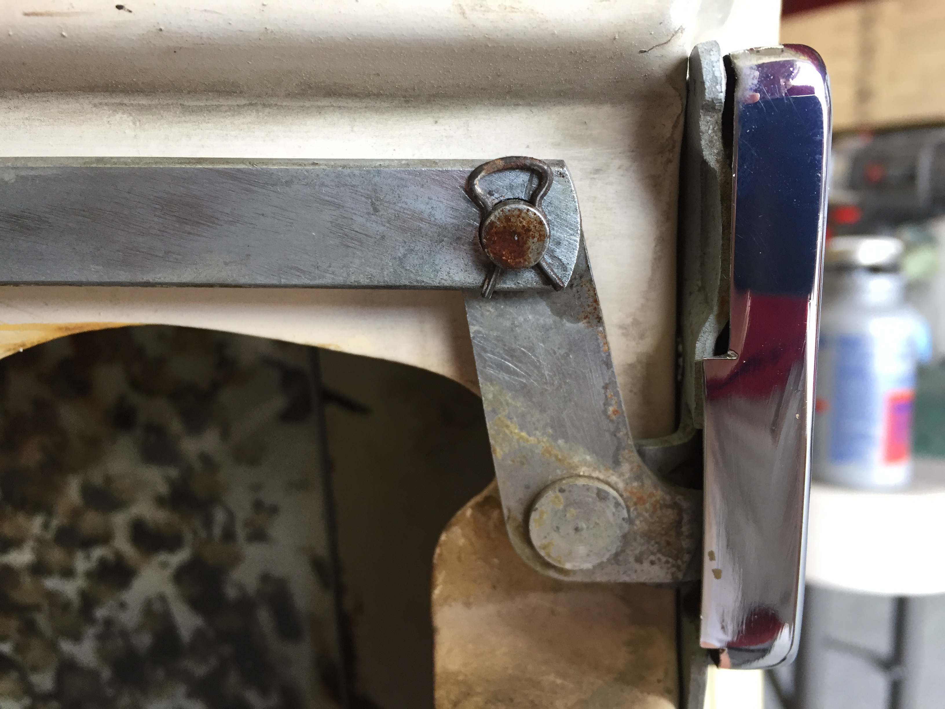
As the Service Manual indicates, ” the appropriate assembly should be held in position inside the door panel and the clearance between the push button plunger and the (“O” in the schematic) and the lock contractor (P) checked through the aperture in the inner door panel. The clearance should be 1/32″. To adjust, release the lock-nut and screw the plunger bolt in or out as required and retighten the lock nut.”
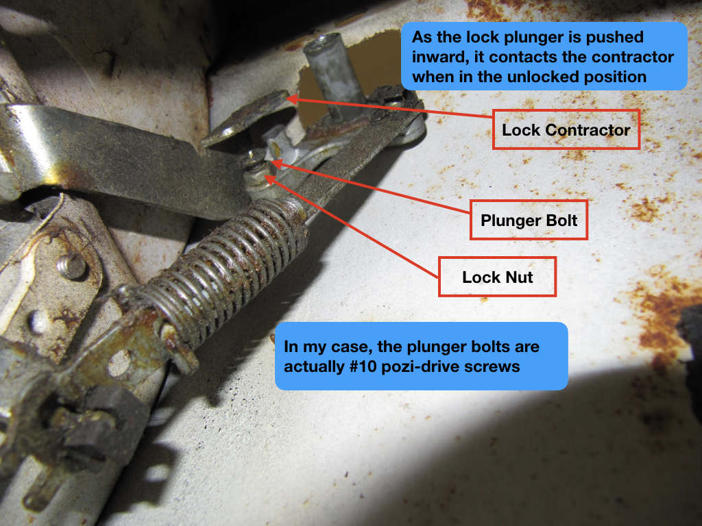
Jag MK2 Lock Plunger Mechanism
I apologize for the confusion in nomenclature, but Jaguar calls the mechanical device below the “remote control.”
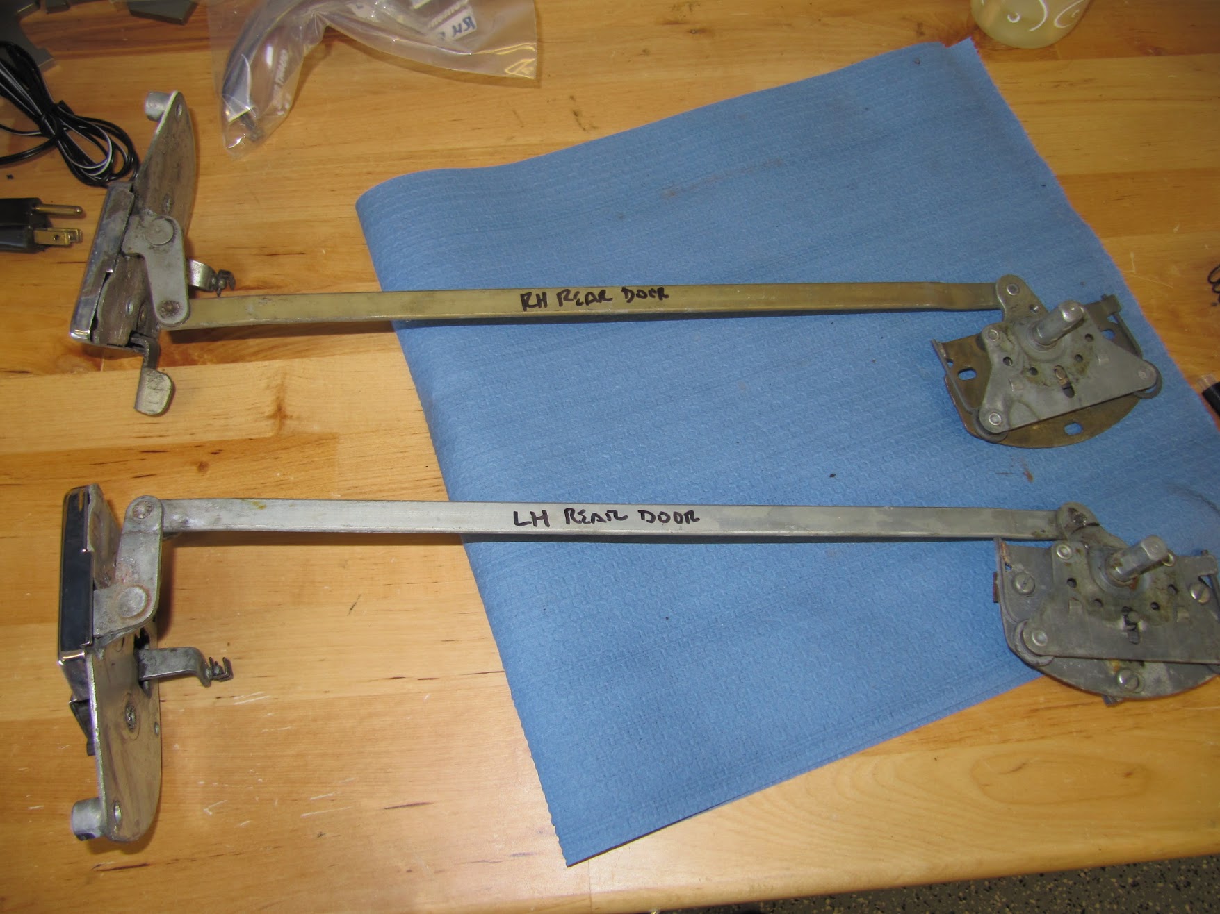
Rear Door Remote Controls with Lock Case Assemblies to the Left
The Service Manual directs that the remote controls are to be installed to the door and connected to the lock case assemblies while in the locked position. This is accomplished with split pins on the front remote controls and with a small piece of steel dowel on the rear doors. The images below show the front and rear remote controls installed on the doors.
Lock Remote Control Installation on Front Door
LH Rear Door Window Regulator Mount and Lock remote Control
Spire Nuts for Door Lock Remote Controls Installed
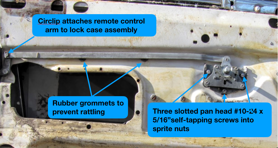
Circlip Connecting Remote Control Lock to the Lock Case Assembly
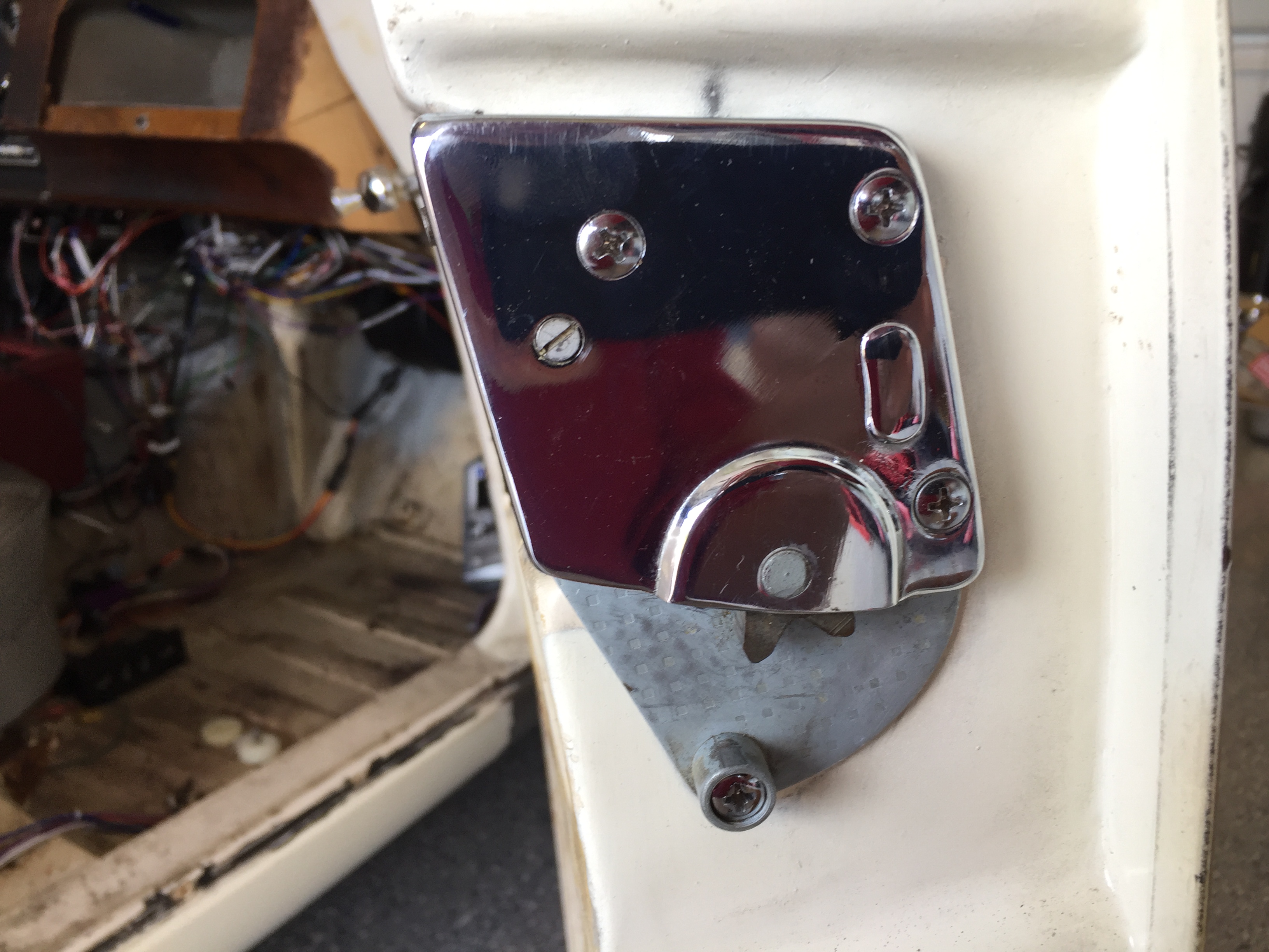
Lock Case Assembly with Four Mounting Screws
The lock Case Assembly is secured to the door with four chrome oval head phillips #10-32 x 3/4″ machine screws.
I replaced the original spire nuts and rubber grommets on each door with new items.