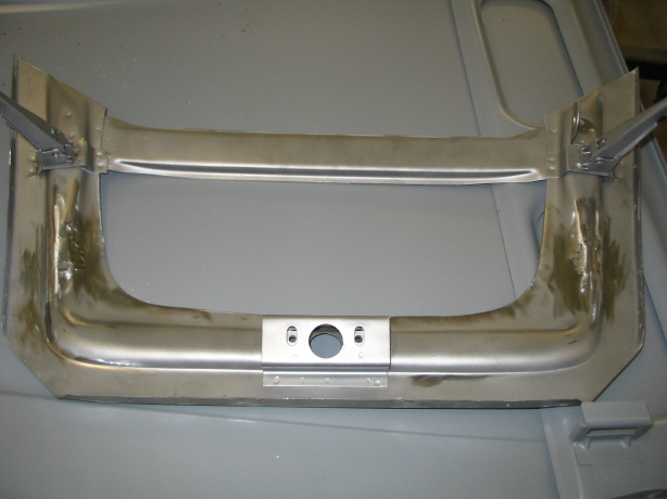
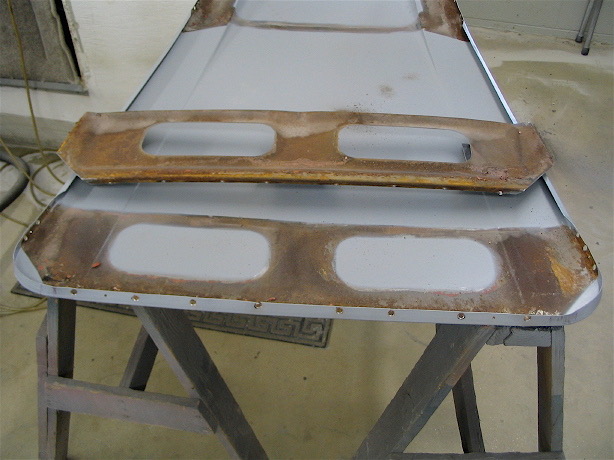
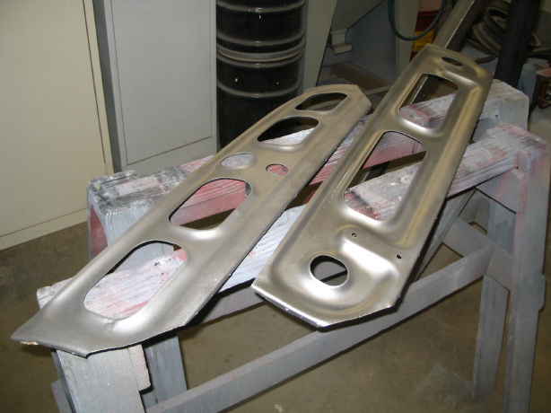
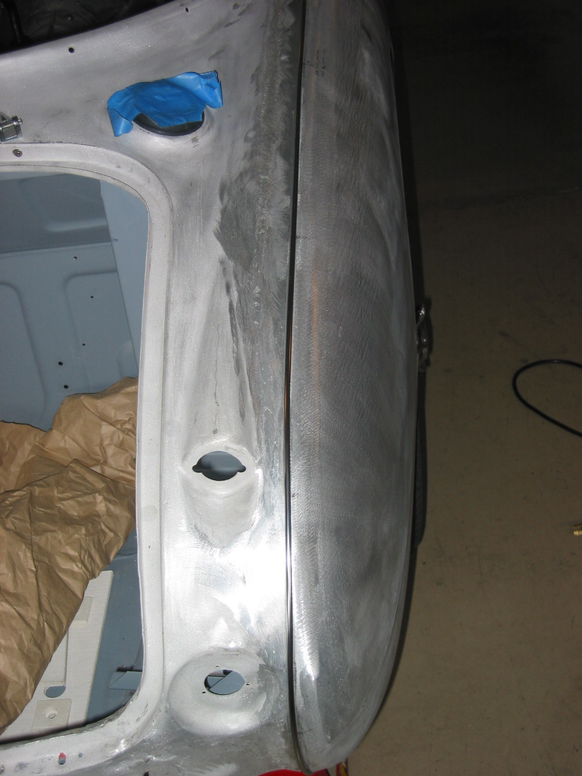
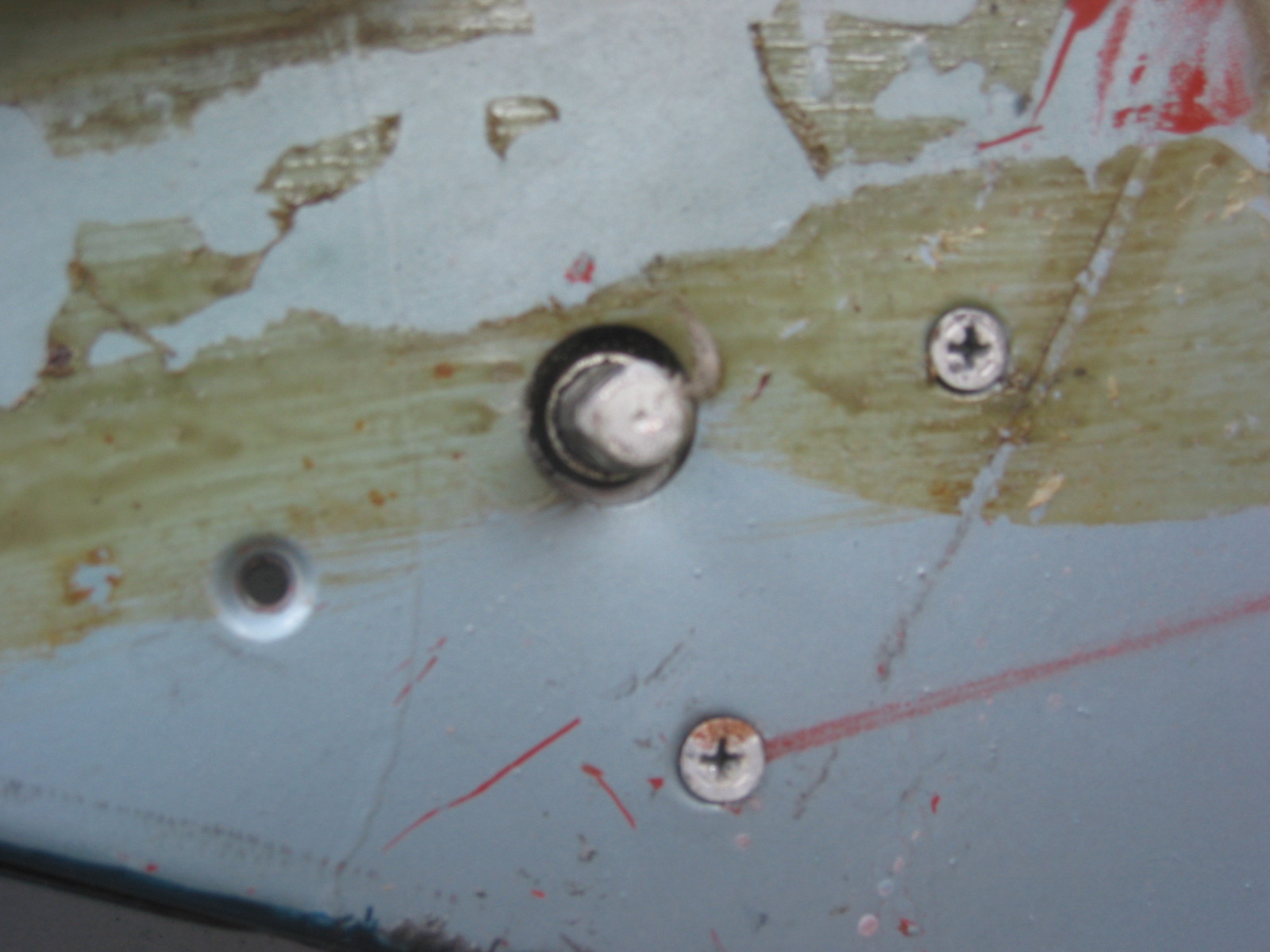
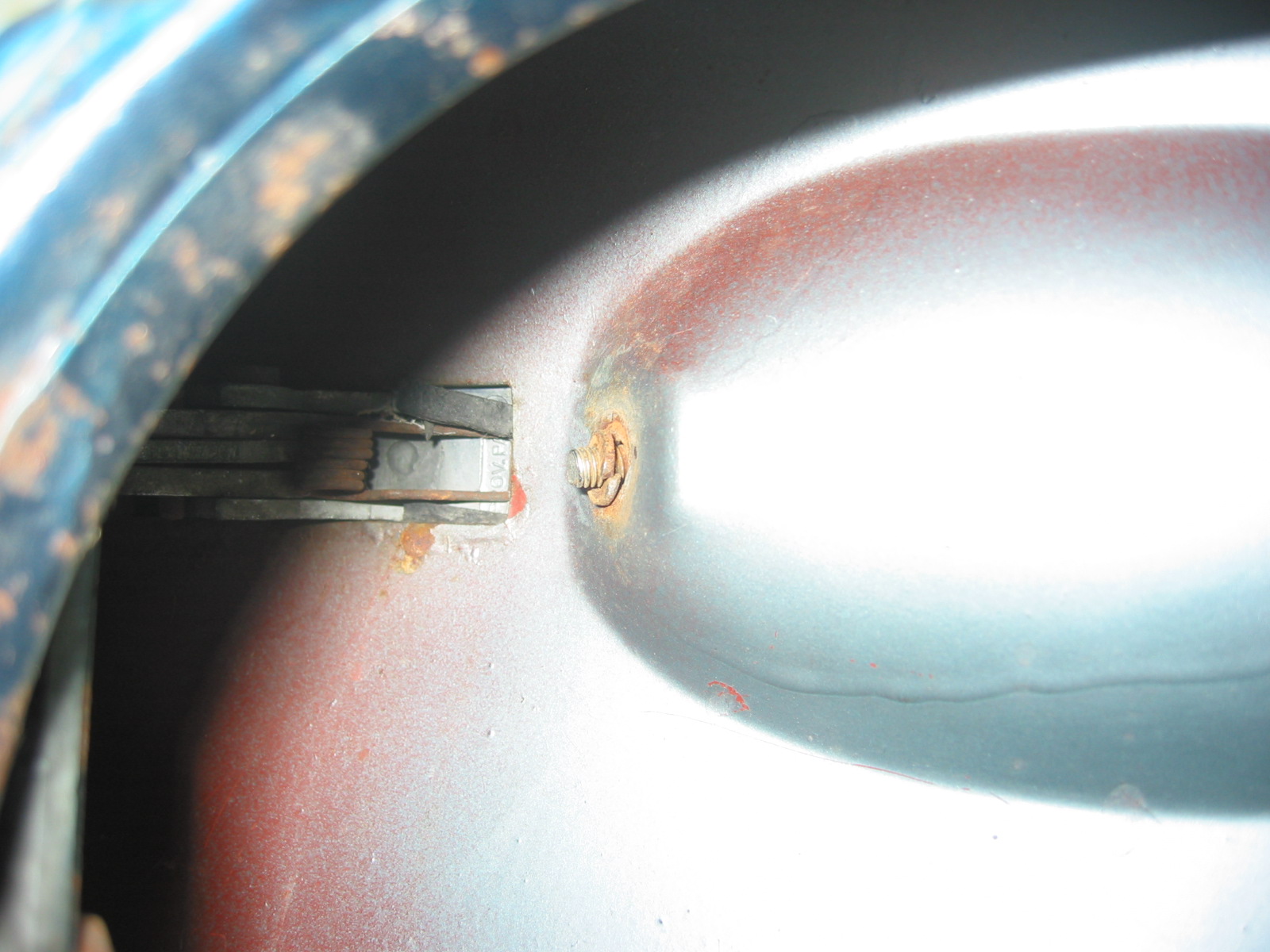
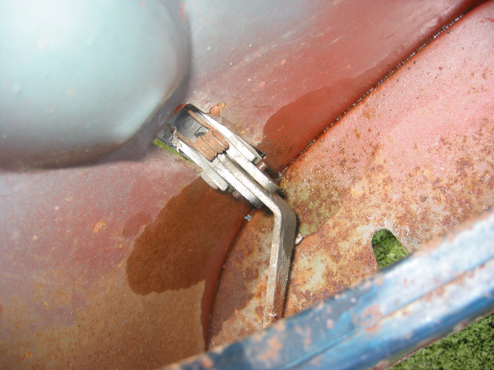
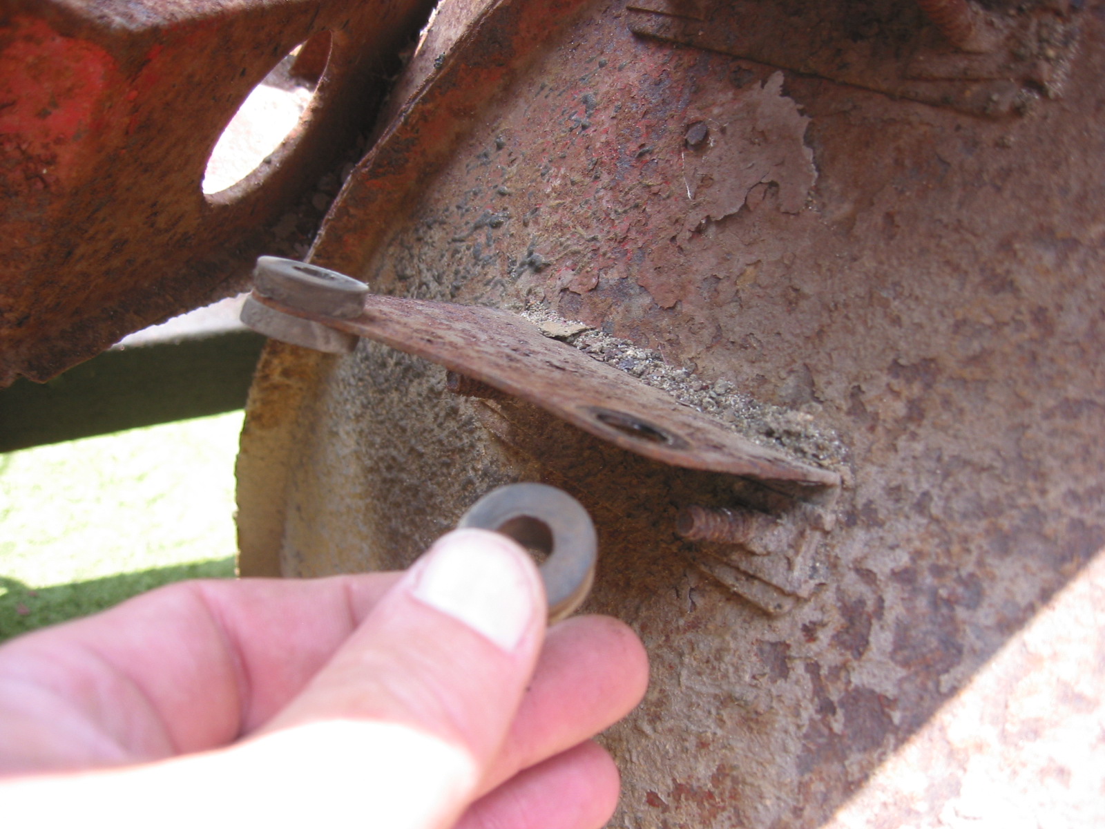
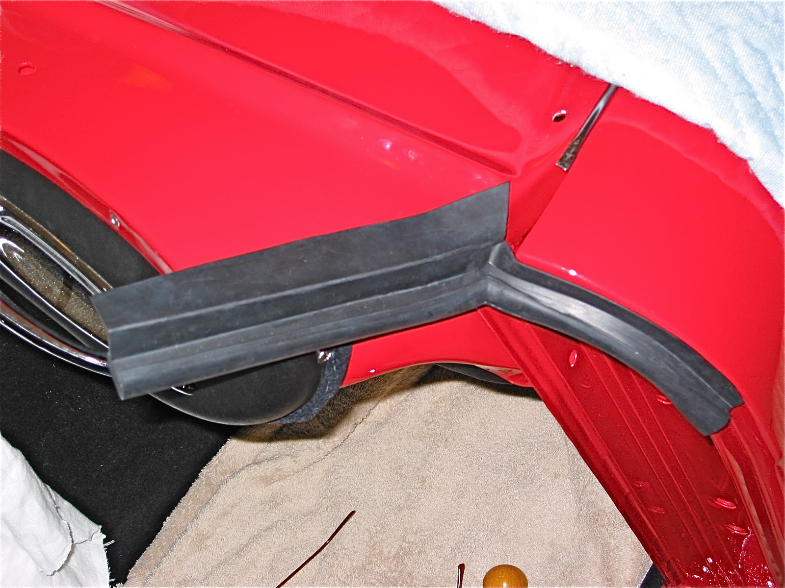
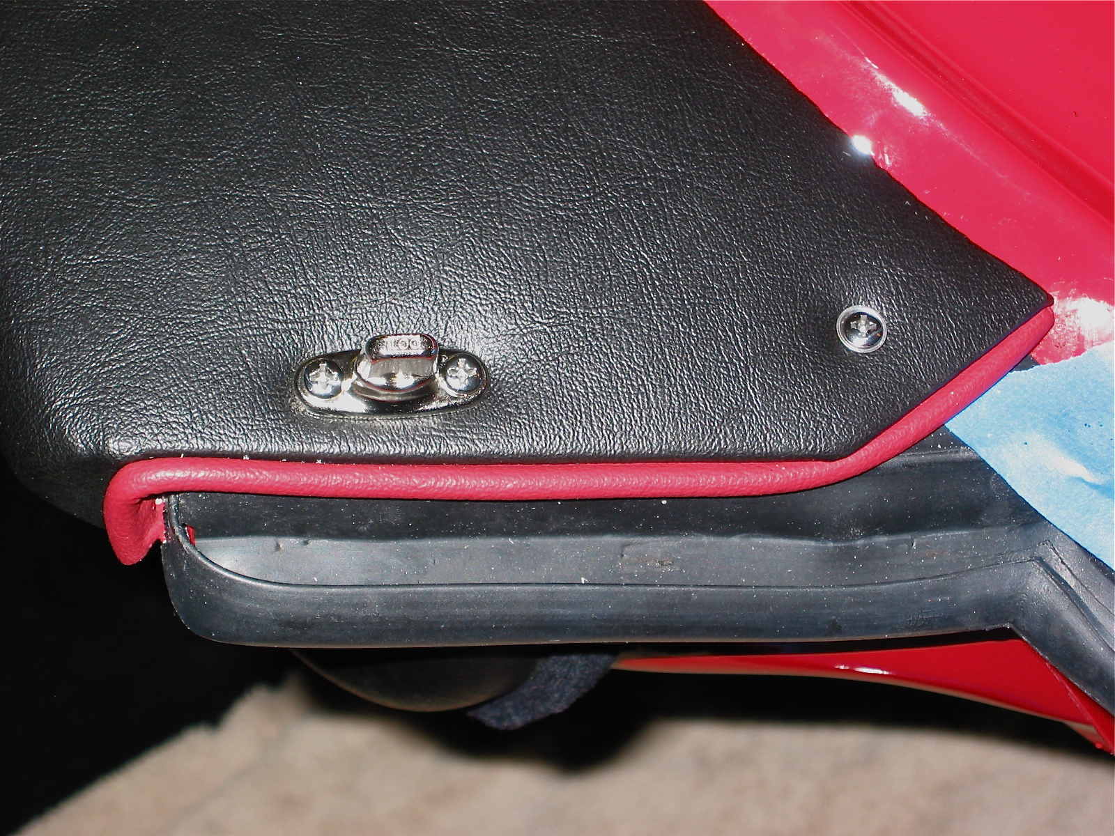
Today (Monday) is Christmas Eve and there is much to be done, so only a little Healey work will happen on this day, but I had a good week. I did manage to install the rubber buffers on the front shroud sill bonnet opening. Three on the left side and two in the right plus the long strip to protect the carbs from the weather. My long strip is cut into two pieces to account for the carb access panel. The buffers are held in place by copper-colored split rivets and flat washersthat are pushed through the mounting hole and then bent over.
LH Rubber Buffers
RH Rubber Buffers 2
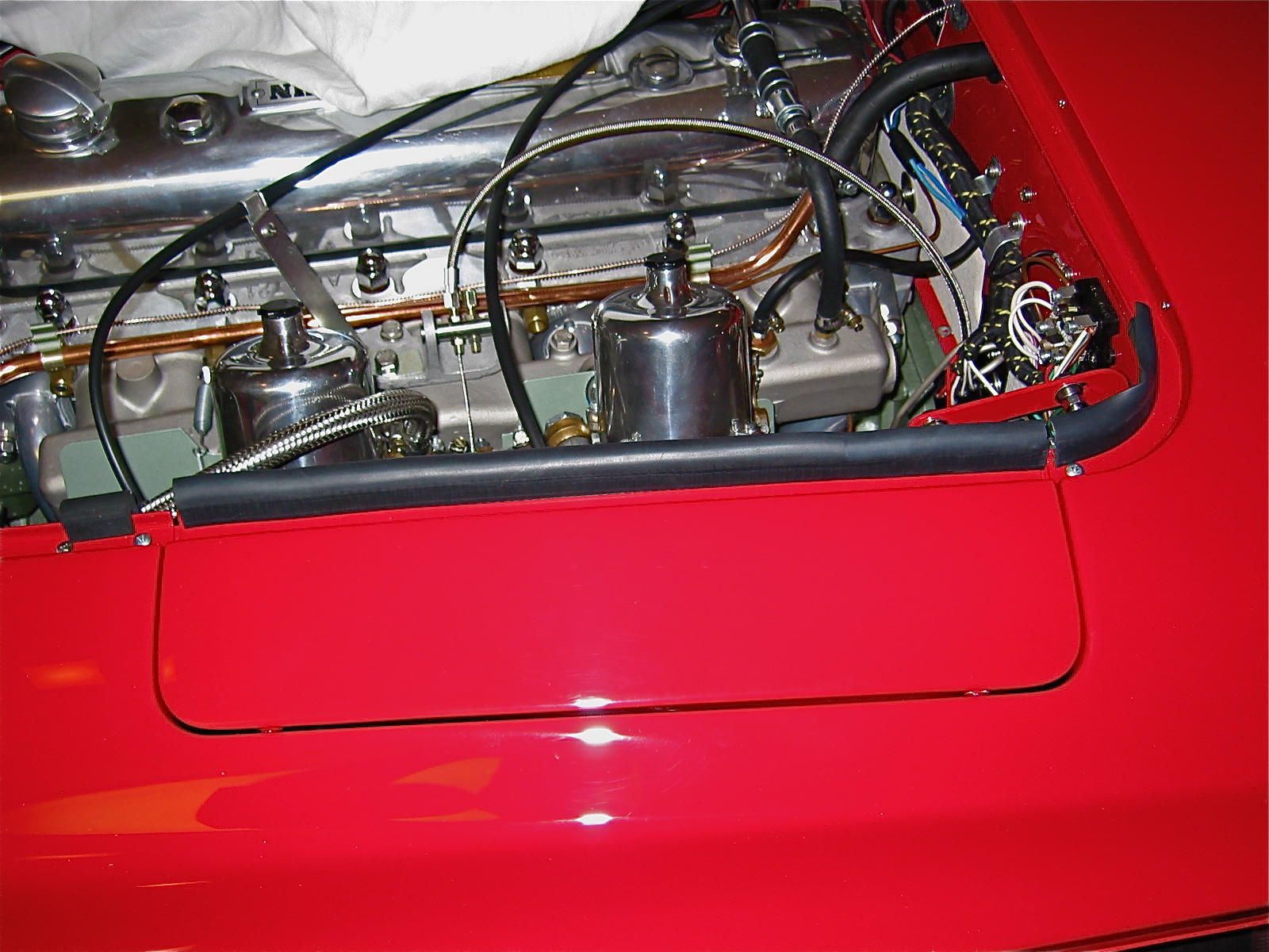
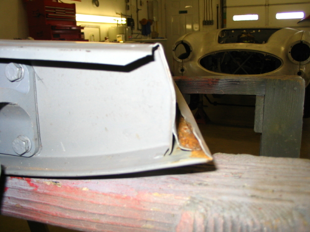
LH Carb Panel Seal
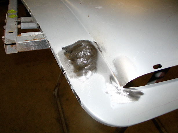
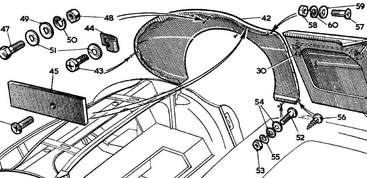
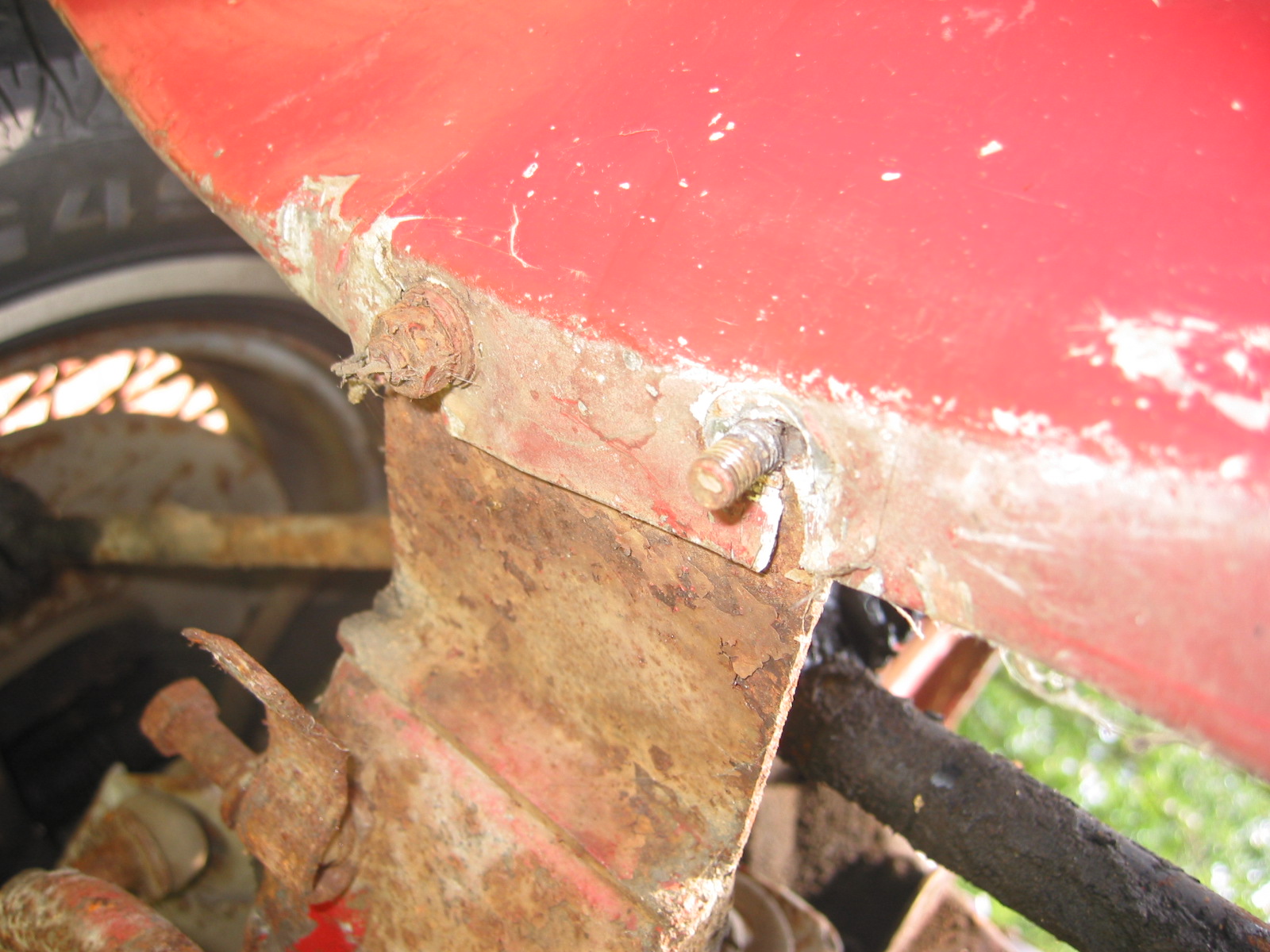
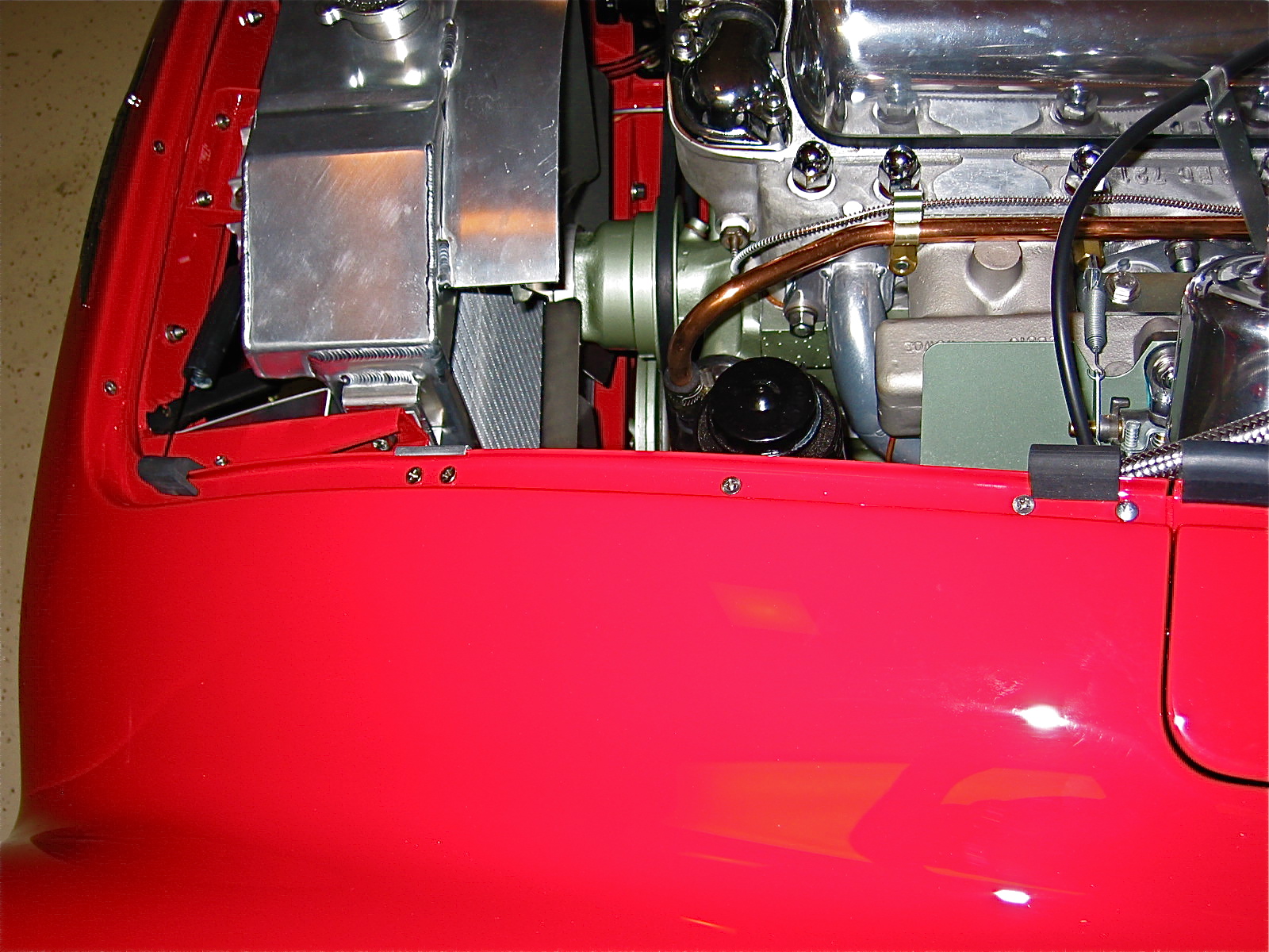
The next task was to fit the front wings to the superstructure. I began with the RH wing, thinking it would be the more difficult of the two. First, I tapped the wing clip nuts onto the wings. Three shorter nuts and bolts are used for the front of the wing, below the headlights. With the help of my wife, who held the wing in place, I installed the rearmost and forward most bolts.
With those two holding the wing in position, I then began to install the other bolts working from the front to the rear. Each one was hand tightened enough to get them started, but with enough room to install the wing beading. The fourth nut/bolt from the front requires Houdini to install. I finally accomplished it after loosening each of the four bolts securing the heater blower and then disconnecting the large fresh air hose from the blower. With the hose loose I was able to access the bolt for the fourth hole.
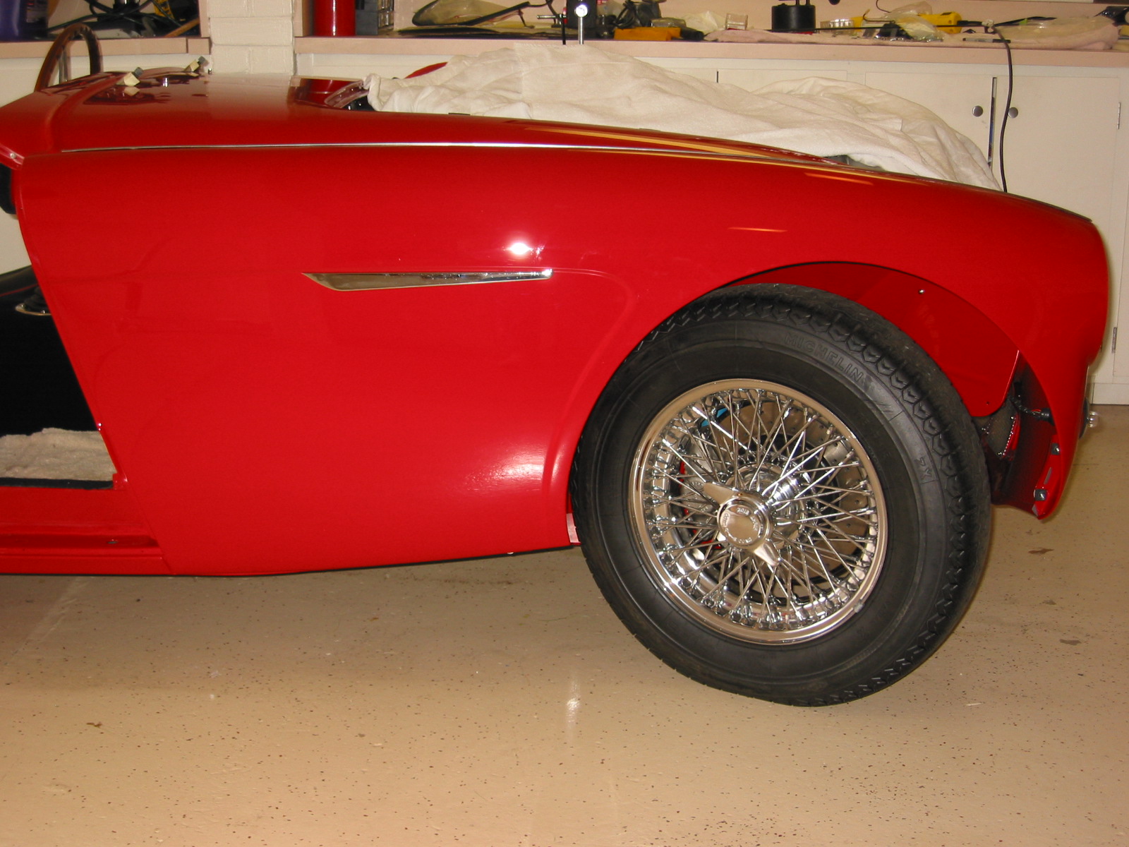
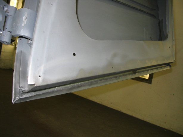
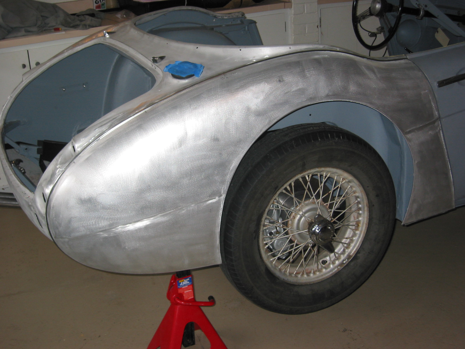
RH Front Wing 1
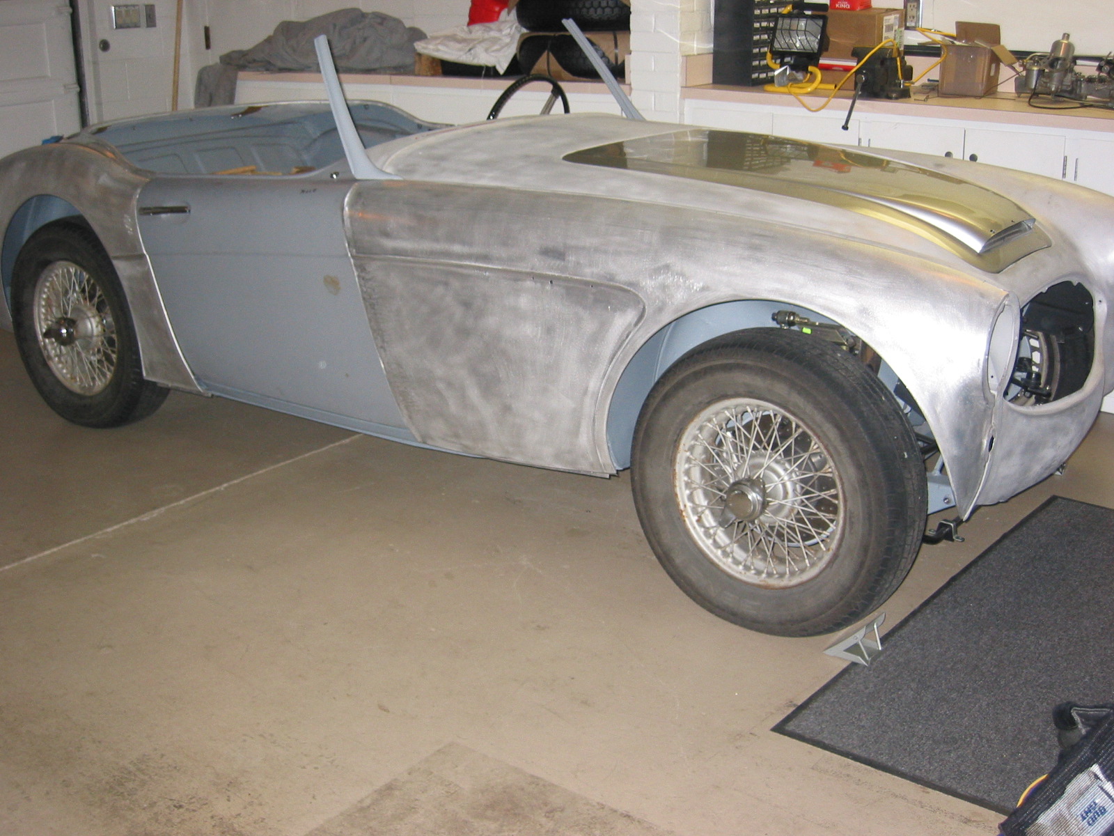
RH Side with front wing
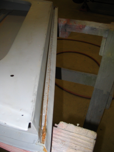
To protect the paint while installing the beading, I ran a strip of painter’s masking tape on the shroud and the wing parallel to the beading.
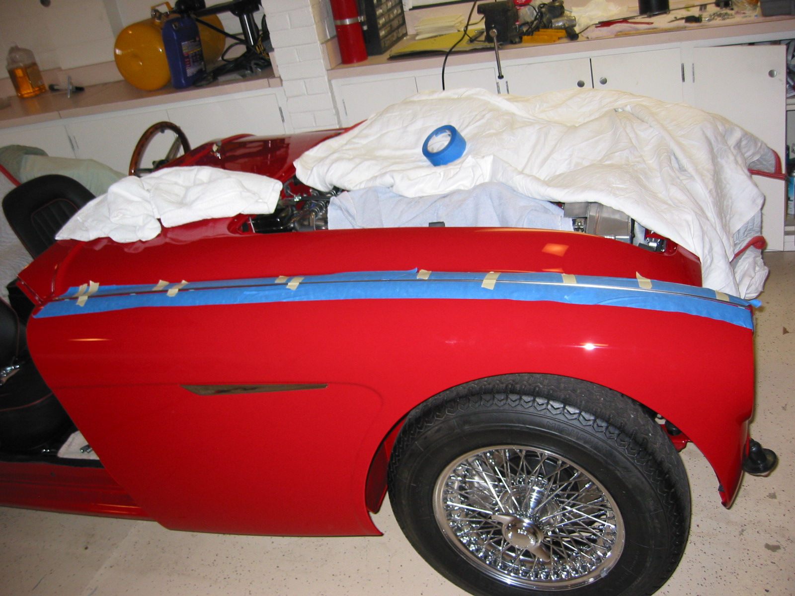
Beading Installation
After carefully spreading the beading folding tabs so that they were evenly distributed across the wing, I pressed it in place. Once again, four hands come in handy!
With my wife applying downward pressure on the beading I tightened each bolt/nut until the beading was locked in place and the top of the wing was tight.
Then I tackled the three fasteners below the headlight. These are much easier to access. Again, I loosely attached each of the three and then inserted the two plastic beading pieces between the panels and tightened down.
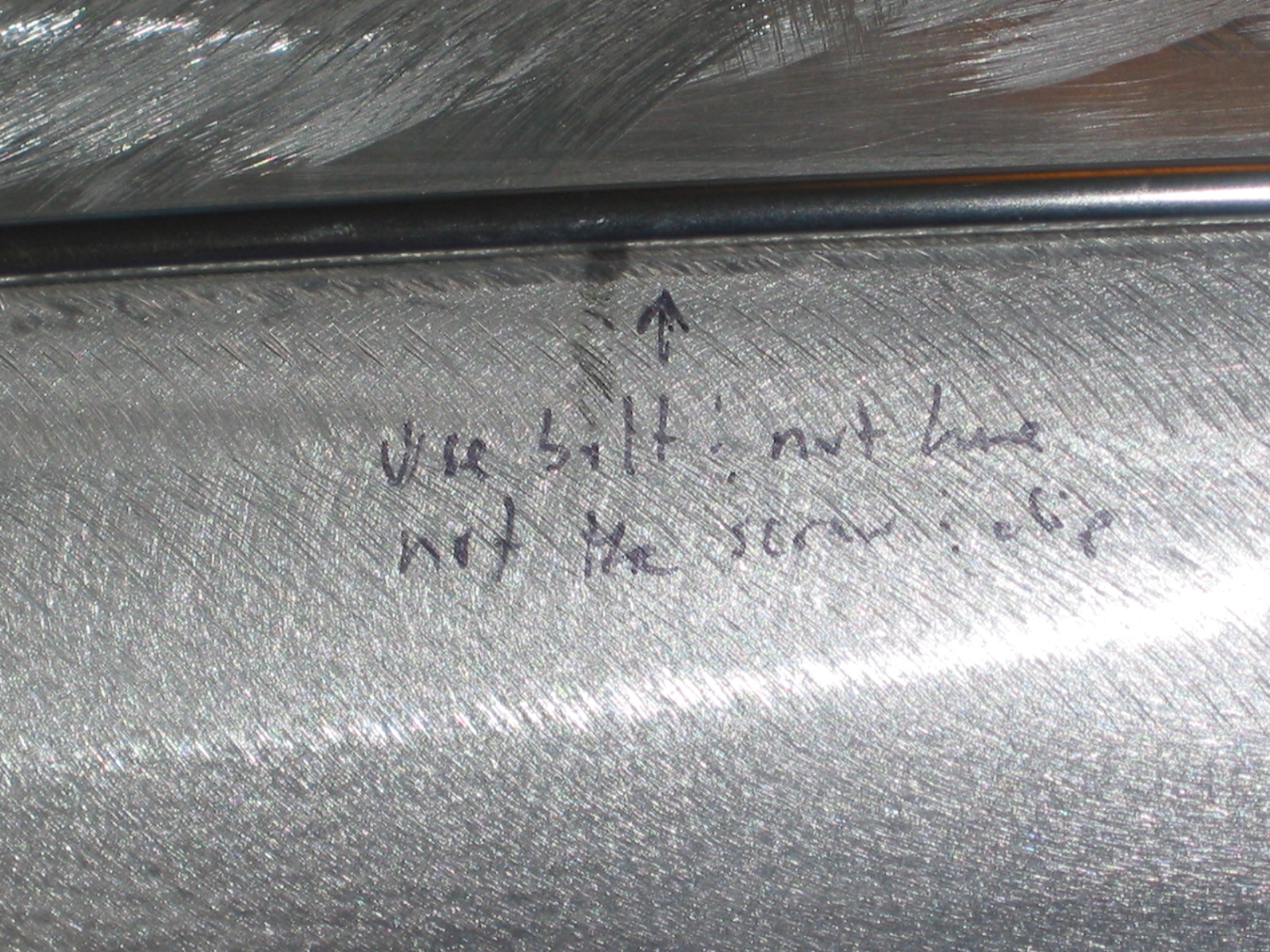
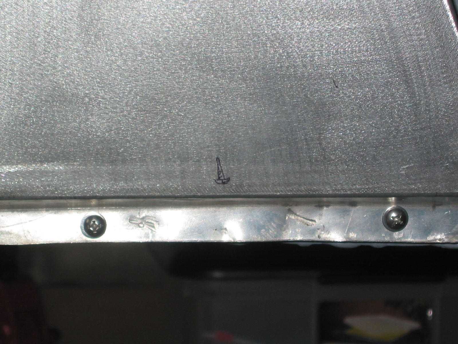
Next were the three 1/4” x 3/4” long hex head bolts used to secure the bottom edge of the wing. Finally, the 3/8” sheet metal screws were used to fasten the wing flanges to the hinge pillar plate. The heater blower fresh air hose was reinstalled and the blower’s four mounting bolts tightened. A little red touch-up paint on the lower bolts and pillar screw heads and then it was on to the LH wing. NEXT TIME I WOULD WAIT TO FASTEN THE WING AT THE BOTTOM UNITL THE DOOR IS INSTALLED. THERE IS FLEX IN THE WING AND BY MOVING IT UP OR DOWN SLIGHTLY ONE CAN BETTER MATCH UP THE WING CURVATURE WITH THAT OF THE DOOR!
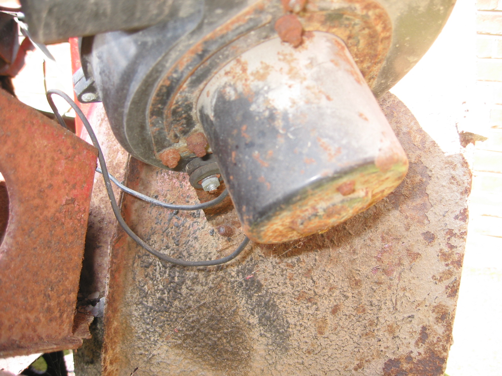
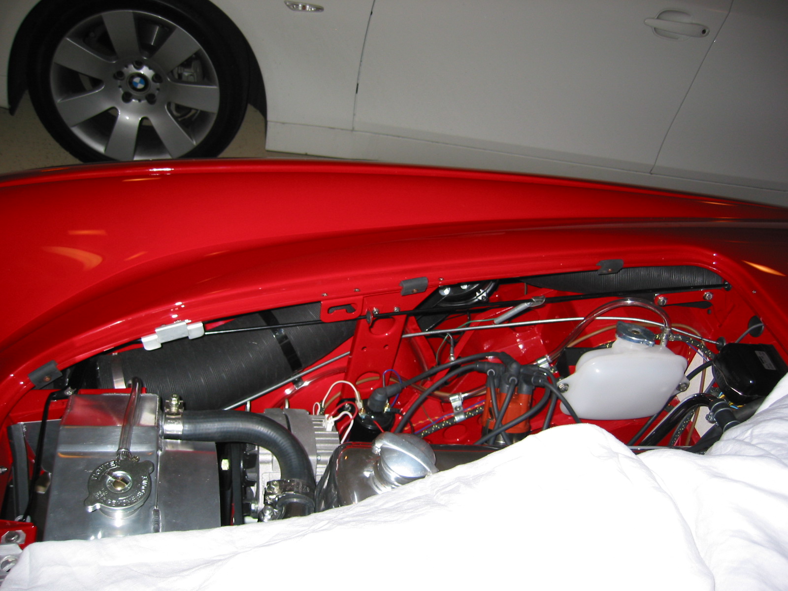
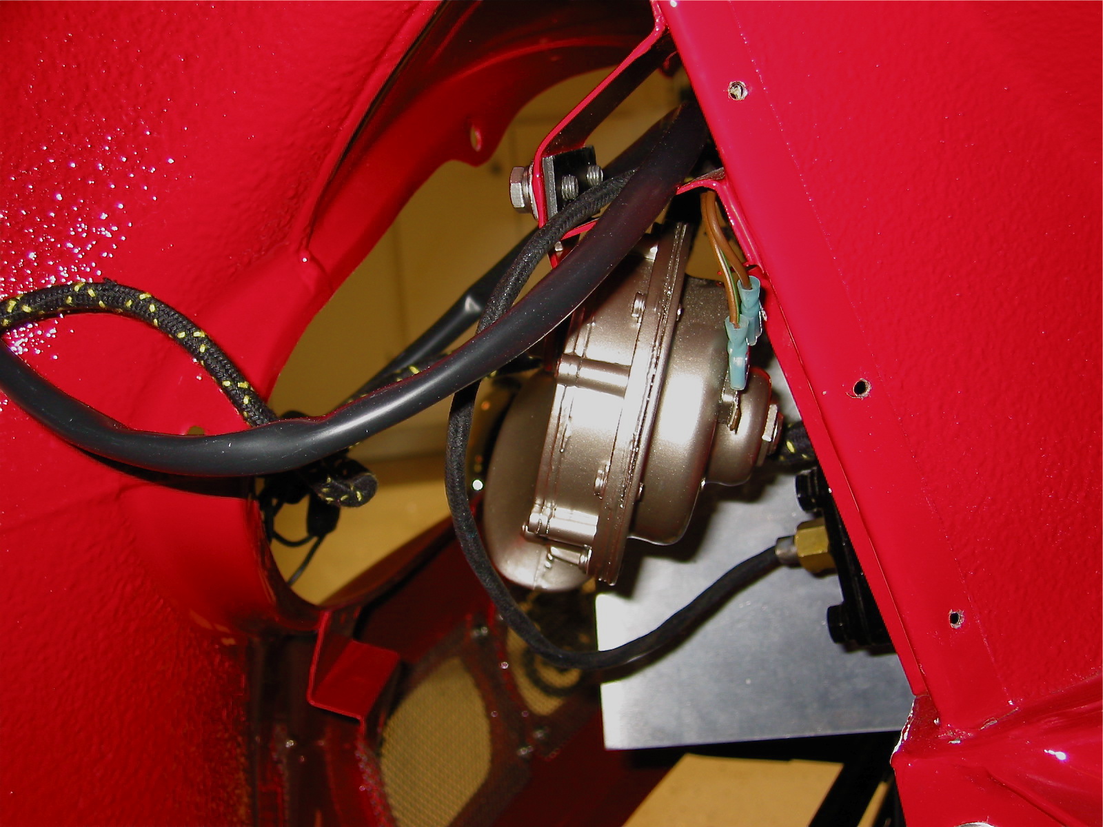
The LH wing was a little easier to install in my case because of the carb access panelI had cut into the shroud! The difficult nuts/bolts on the LH wing were the rearmost two because the wiper motor restricts access to the locating holes and hardware.
It was a good feeling to have all four of the body’s wings in place.
The next task was the installation of the scuttle seals that I had ordered from Bill Bolton. These are reputed to the best available, and the fit does seem to be quite nice. As I was working on the seals and dash pad I had a visit from grandson #2, Shane. As the image shows, he seemed right at home in the Bloody Beast.
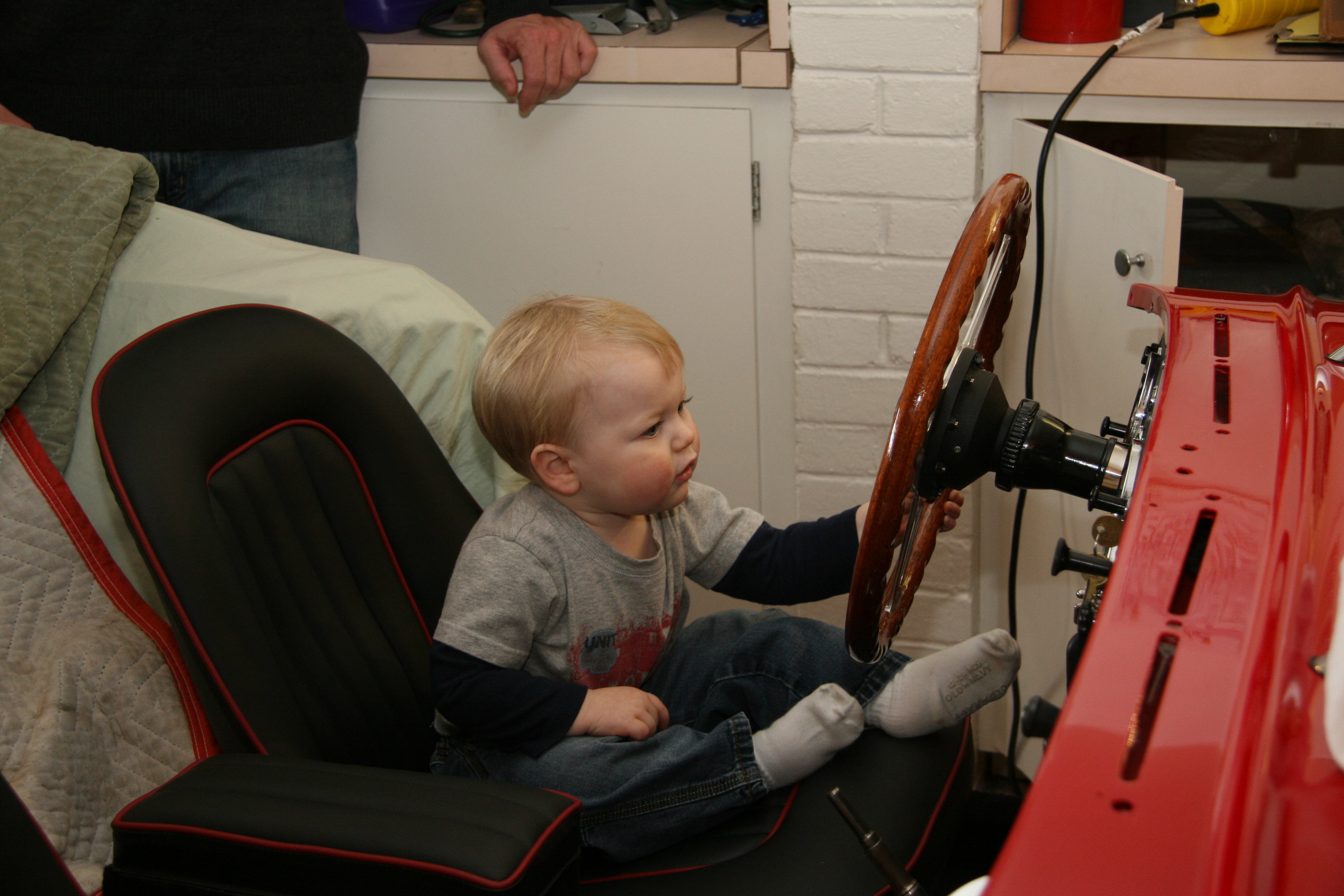
Little Shane’s visit to the Garage
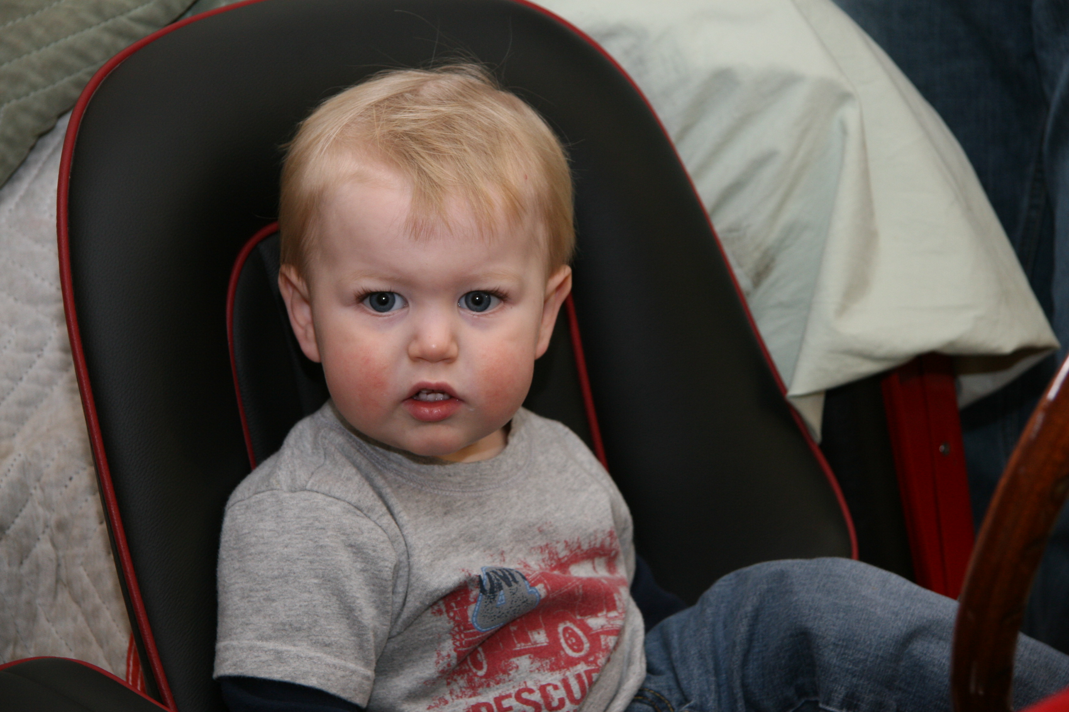
Little Shane’s Visit
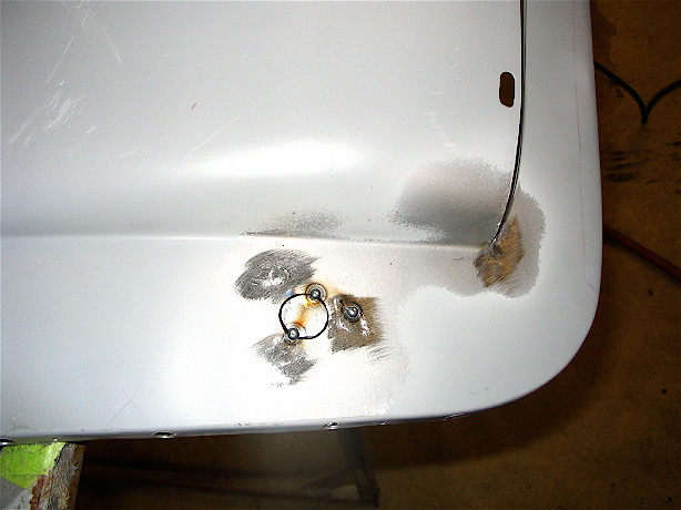
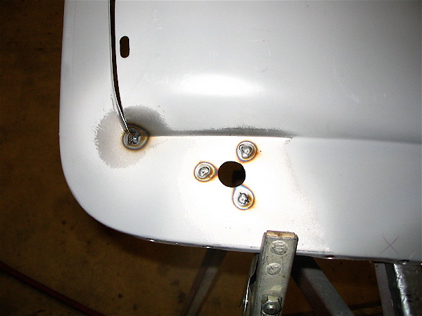
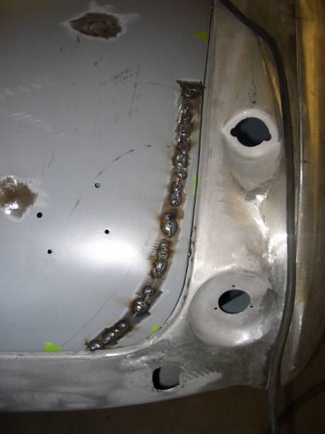
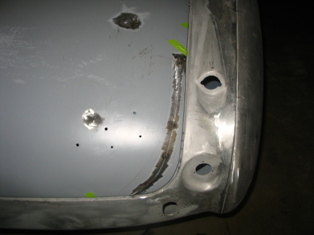
Fitting the scuttle seals was not as difficult as I expected. The job was made much easier by following directions: Scuttle Seal Install Rich Chrysler along with those provided by Bill Bolton.
Scuttle seal 1

Scuttle seal rivets 1

scuttle seal screw holes

Scuttle seal rivets 2
I then installed the dash pad, along with the hot air outlet defroster masks, the mirror, tonneau turnbuckles, and the stud for the tonneau cover.
Dash Pad seal 1
Dash Pad seal 2
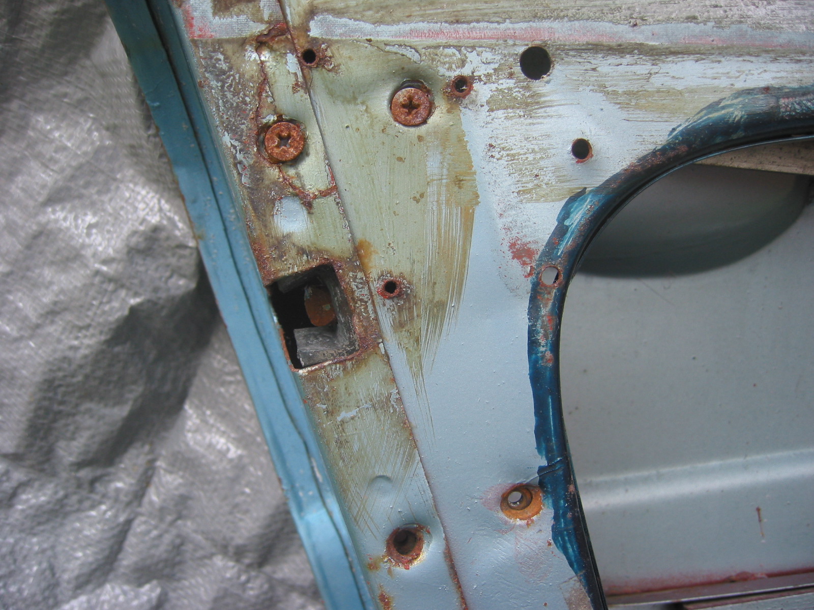
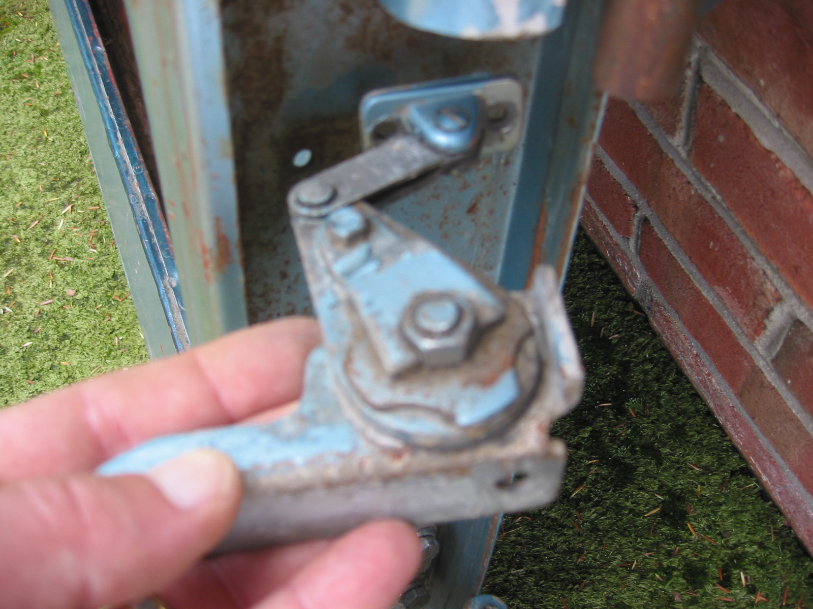
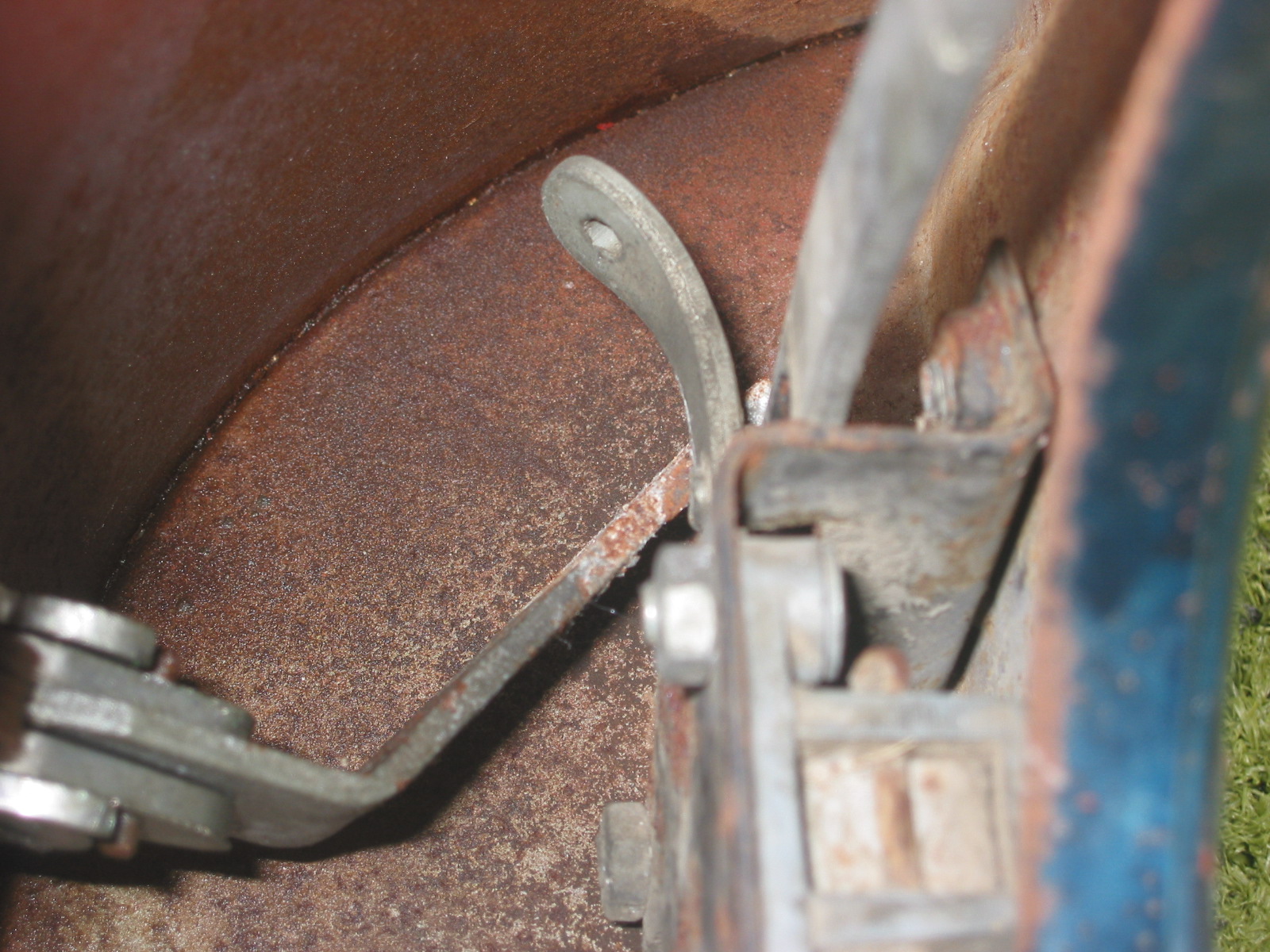
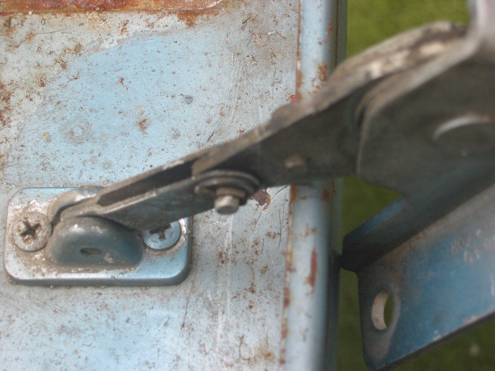
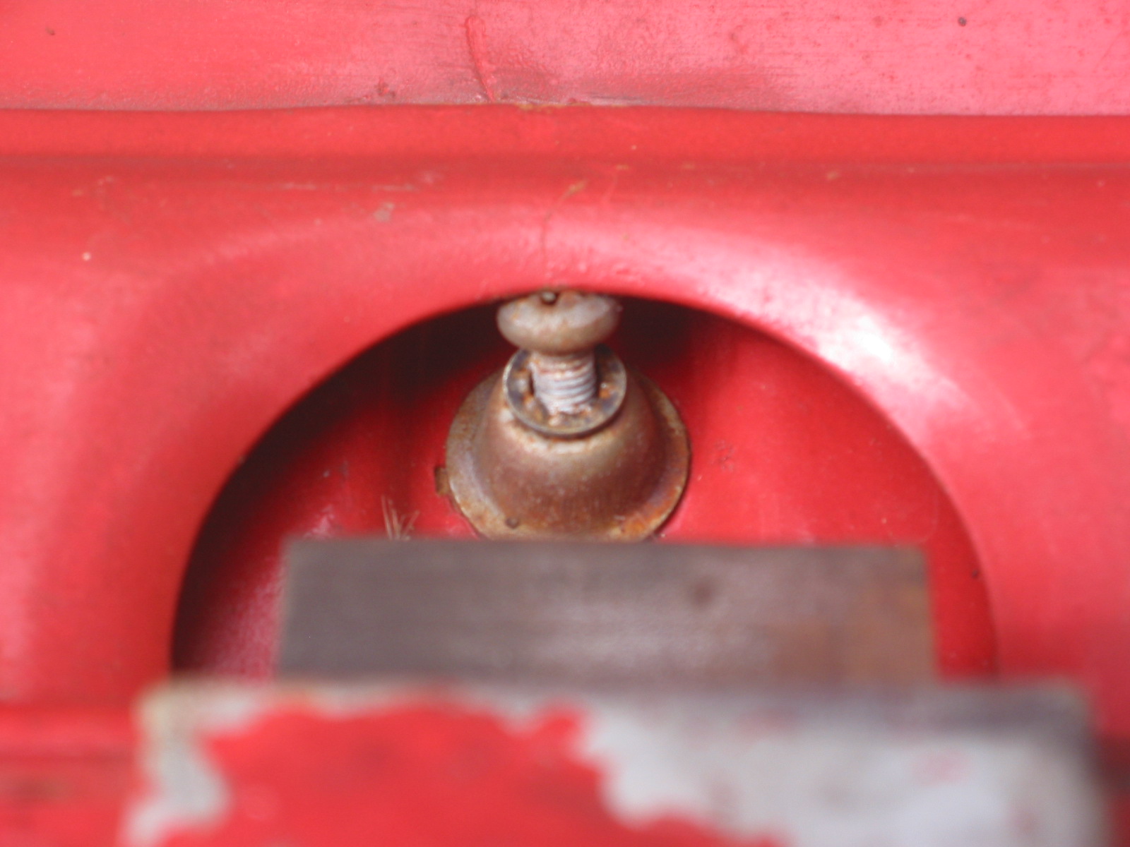
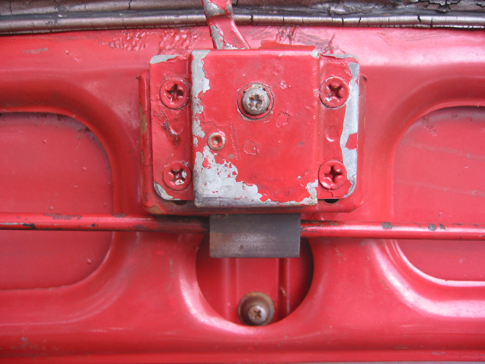
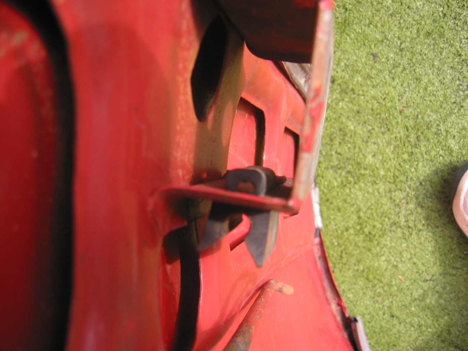
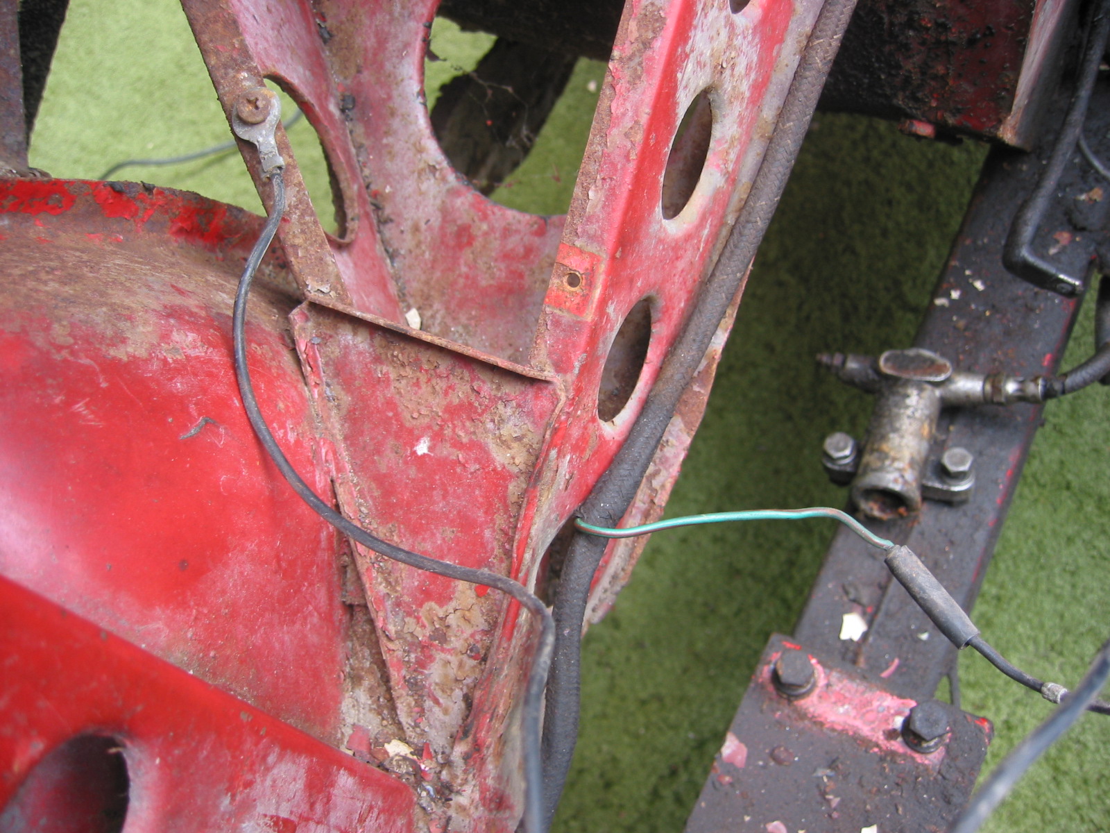
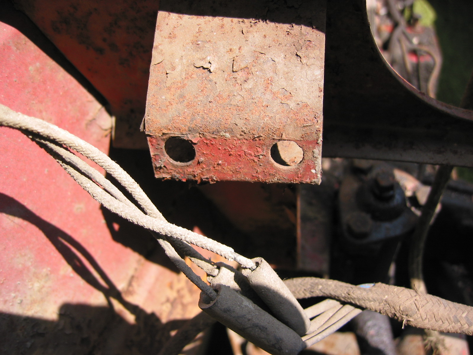
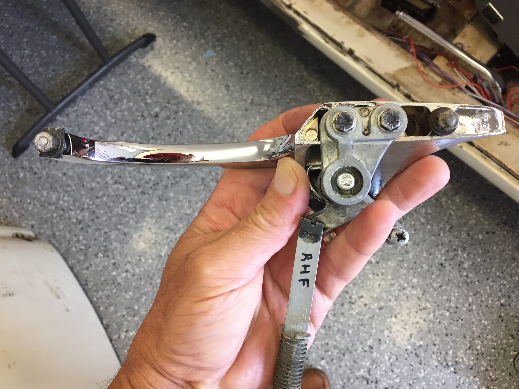
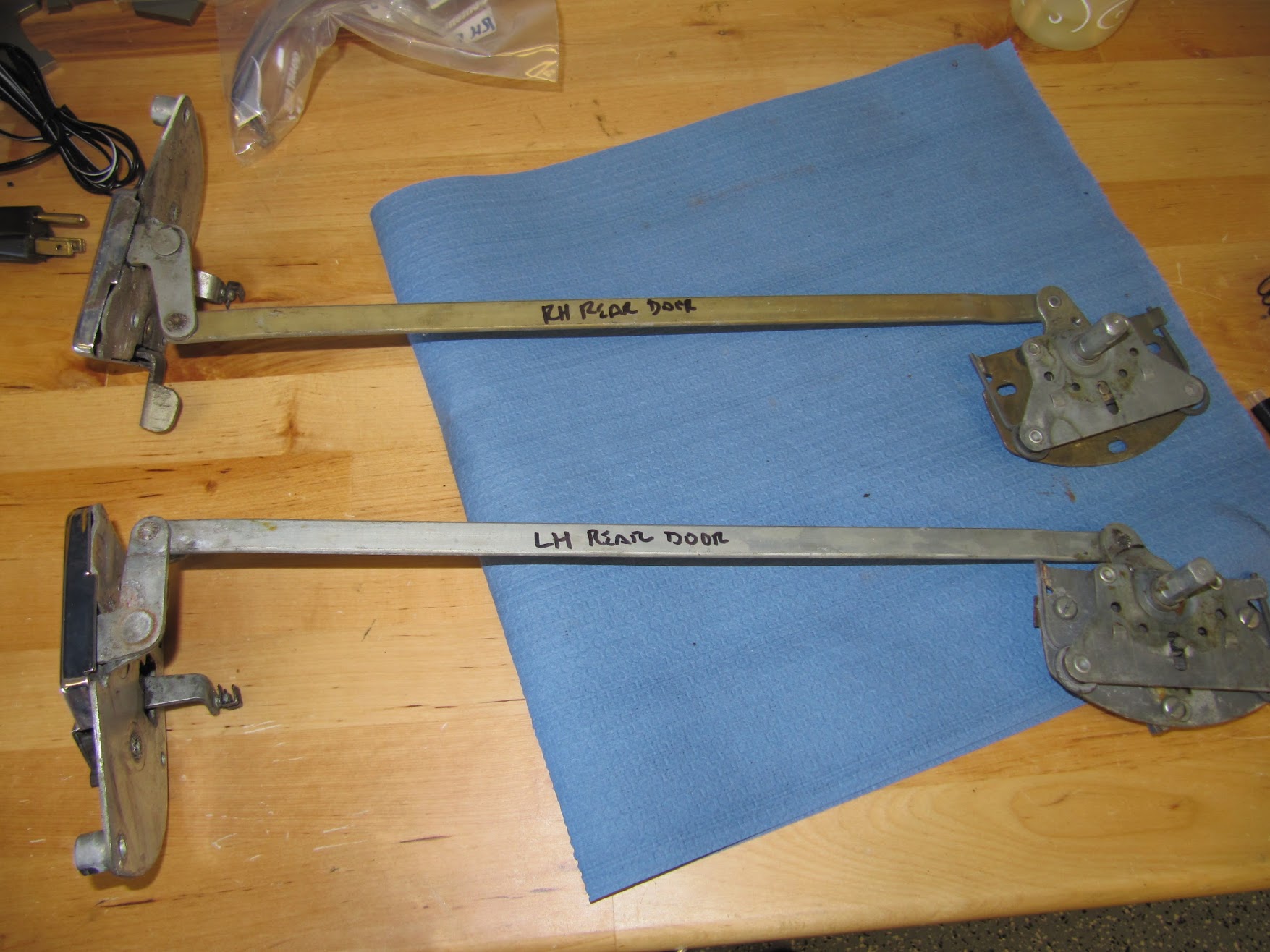
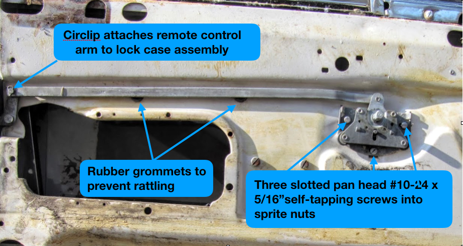
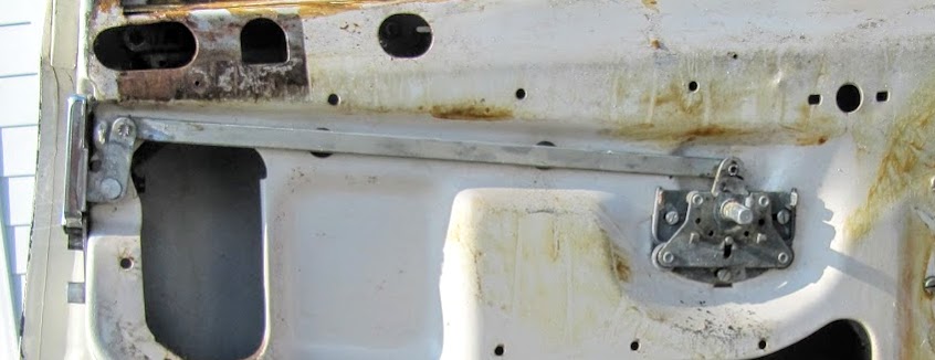
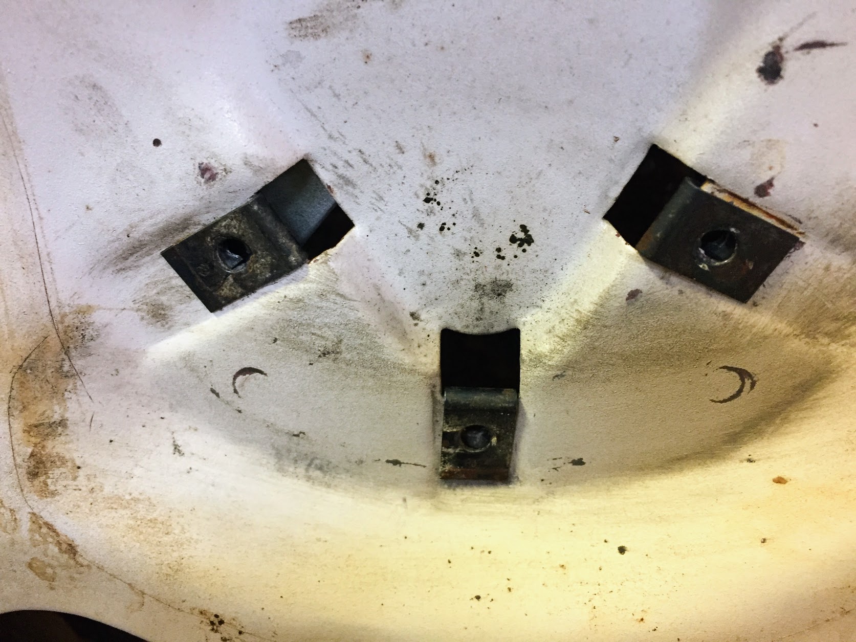
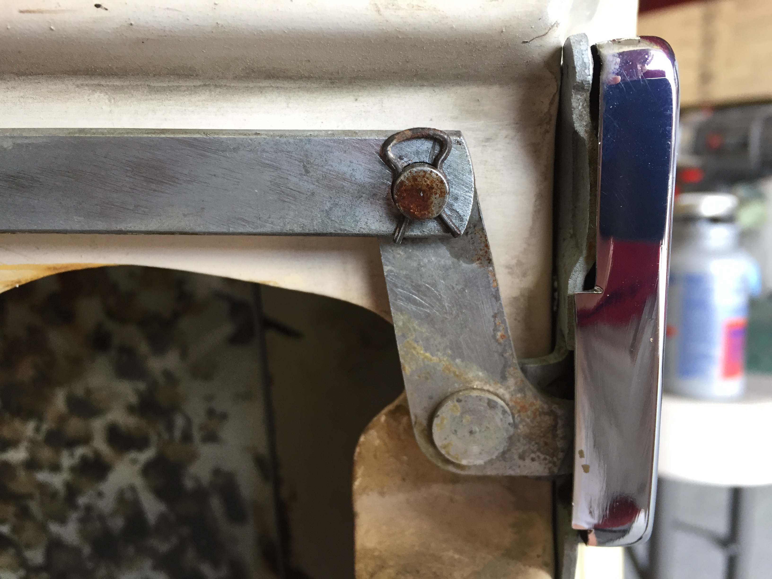
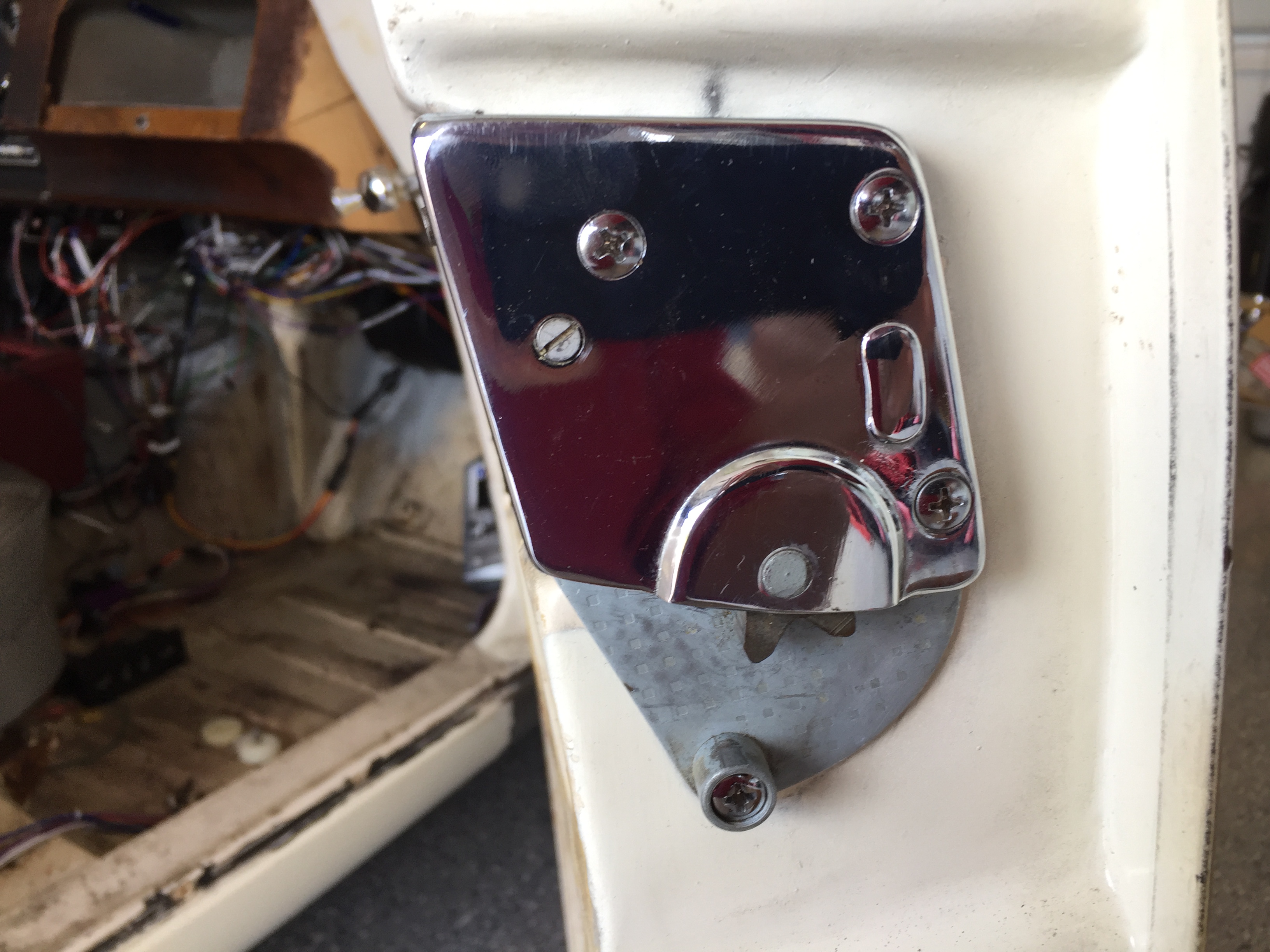
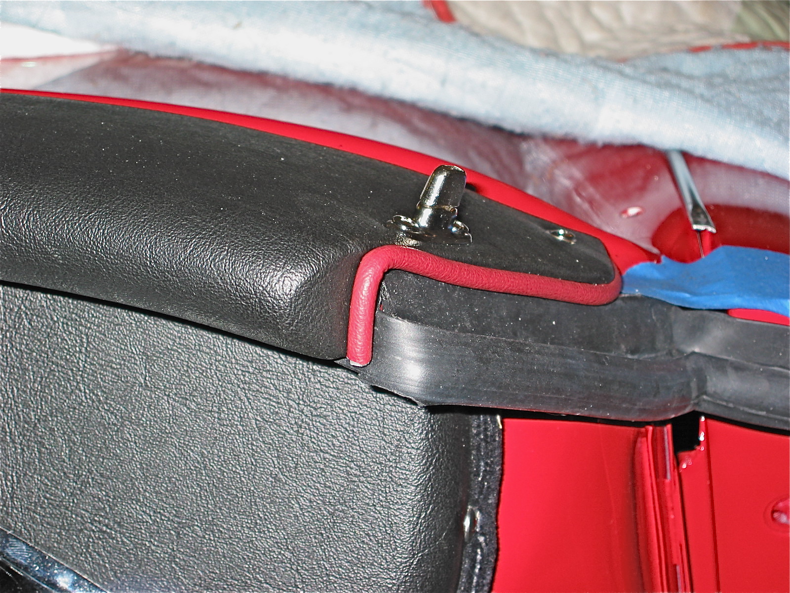
Once the dash and accompanying hardware was installed I was ready to begin the door installation. I first attached the door check strap assembly to each side. Then I taped all the edges of the wings, sills and doors with painter’s masking tape for protection.
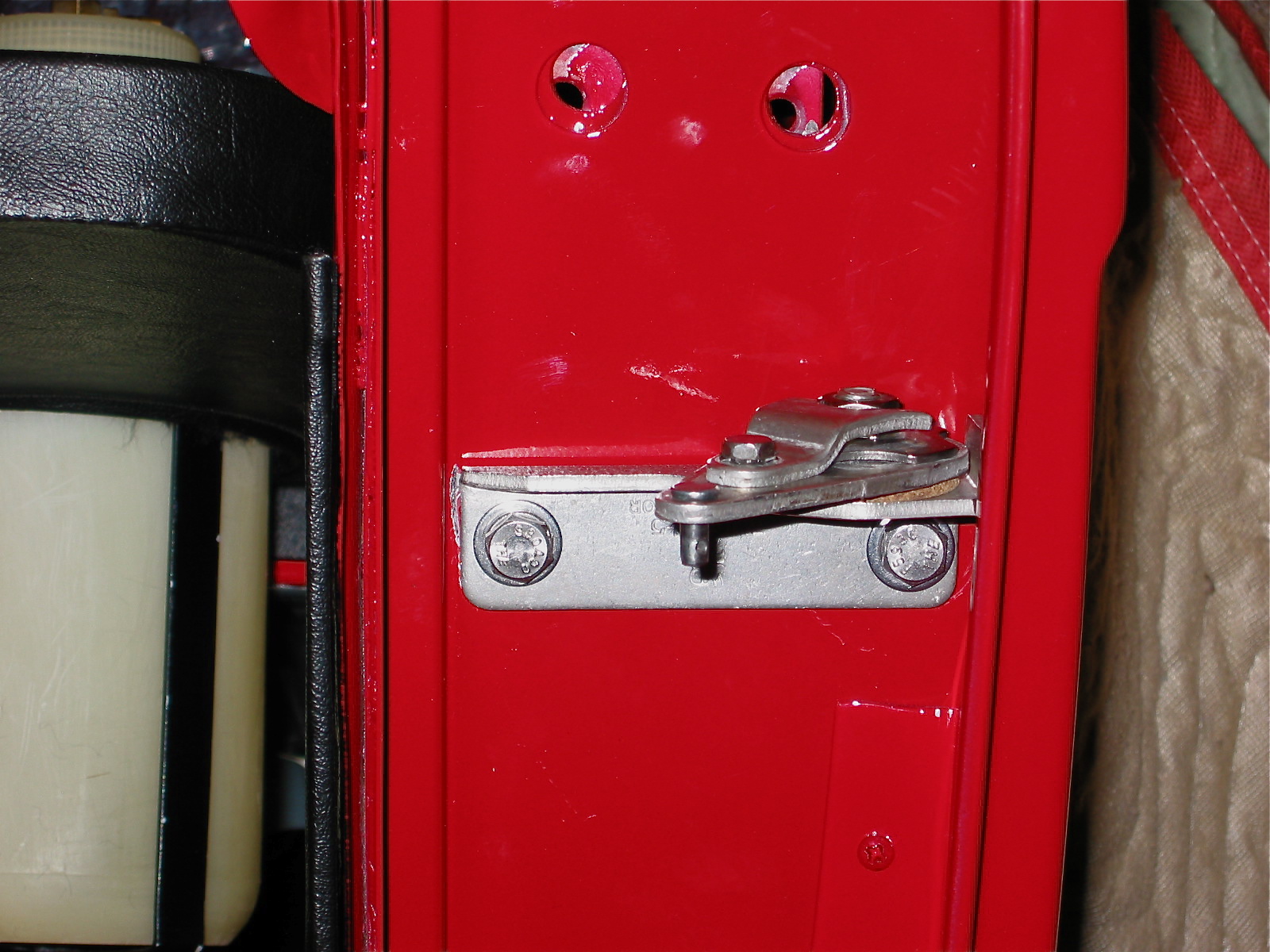
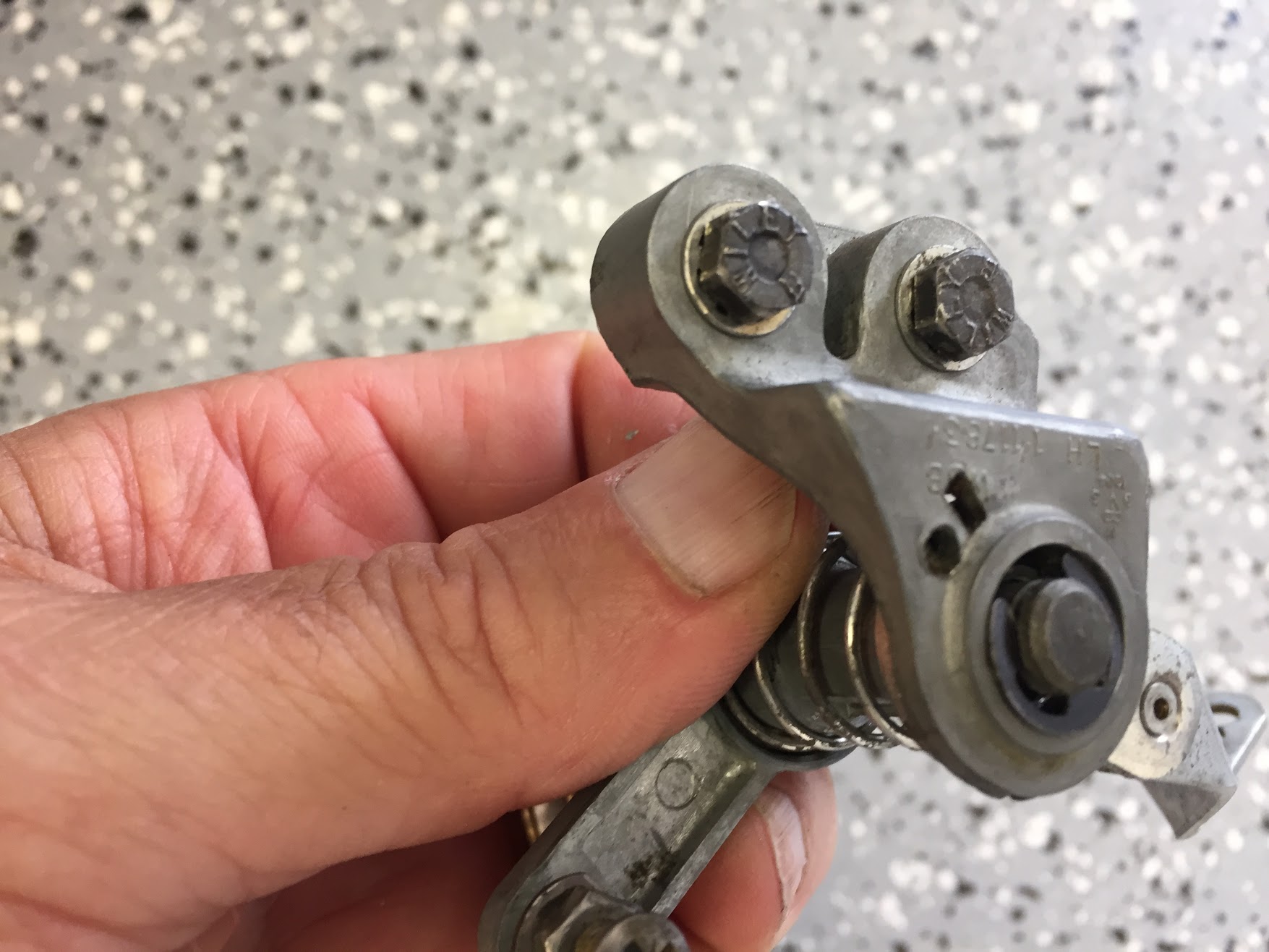
Check Strap Assembly 2
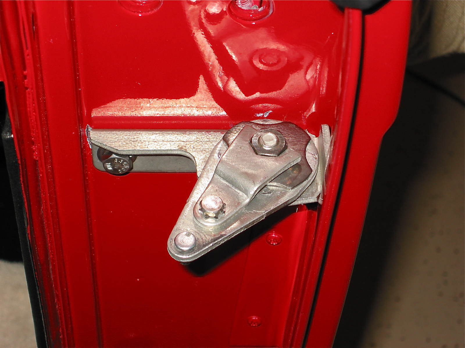
Check Strap Assembly 3
My son John (23 years of age and strong) lifted the doors in place and I ran in the door hinge screws. This job was actually easier and less time intensive than I imagined. Of course, I still need to adjust them for proper fit. I had previously attached all the door interior upholstery, trim and hardware which was much easier than installing it all on the car, but it did make the doors quite heavy.
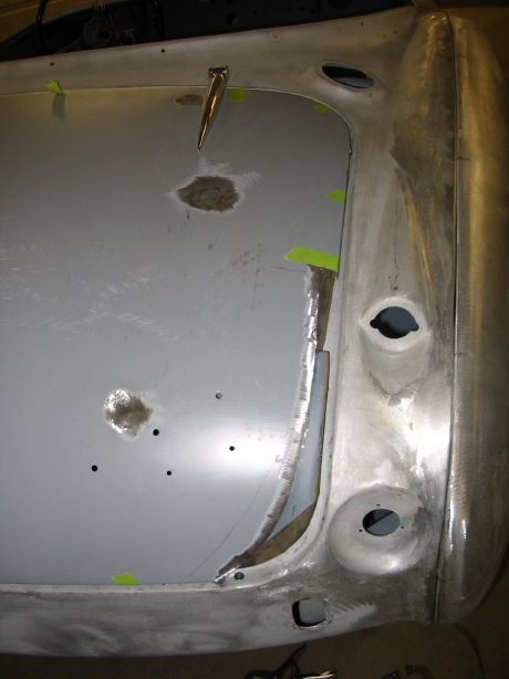
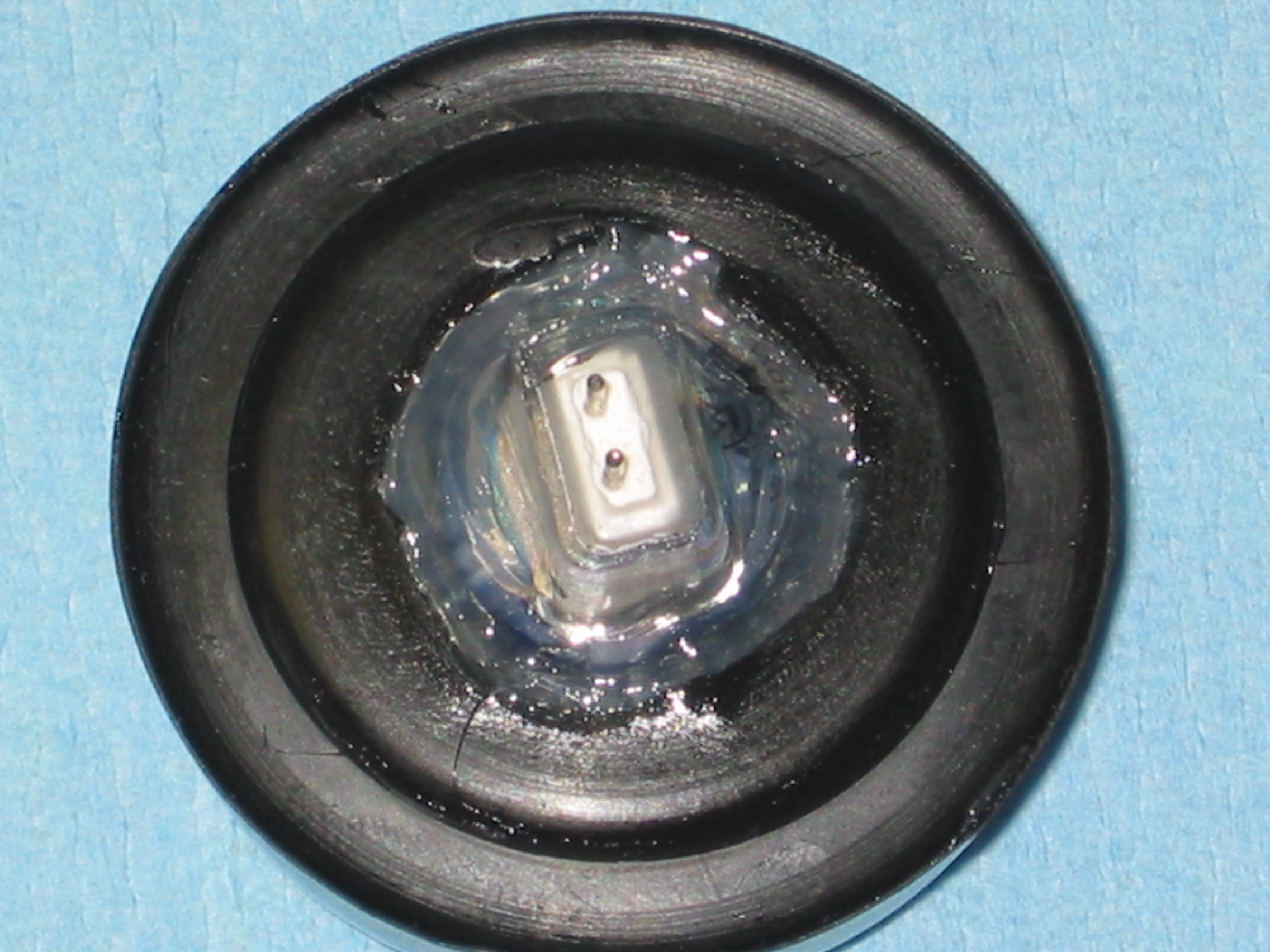
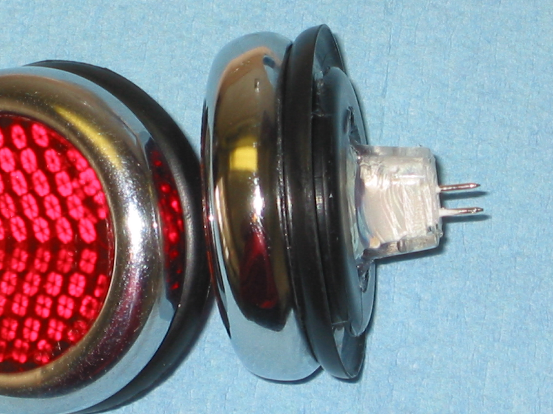
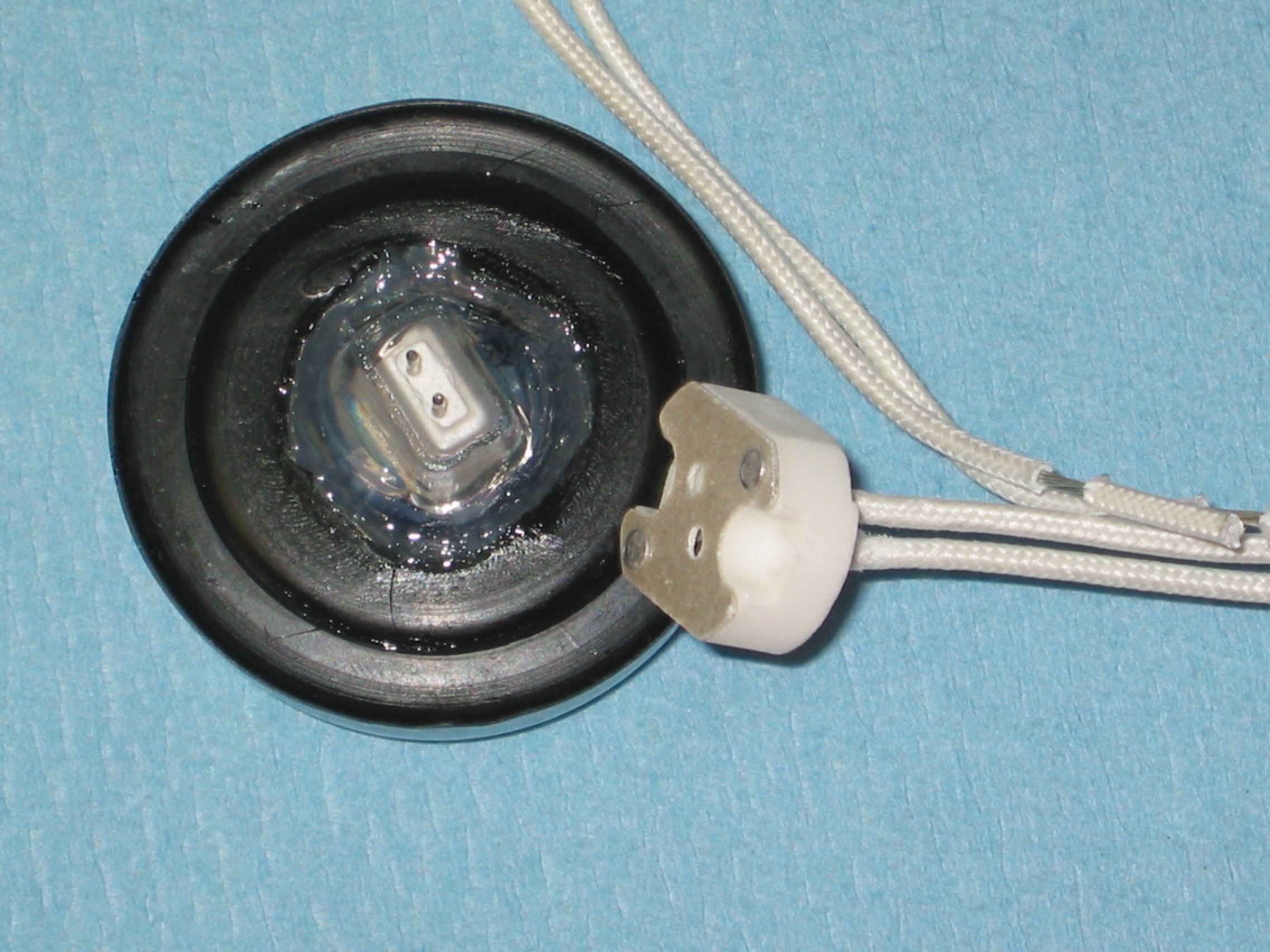
Next on my list was the installation of the headlight buckets, headlight bulbs, and the chrome lens retaining rim. It wasn’t necessary, but I jacked up the front of the car and temporarily removed the splash shields and the tires to give easier access to the rear of the headlight buckets. I experienced a little difficulty with mounting the trim rim but eventually got it to lock into place. Then I secured the parking/flasher light assemblies to the car with the three small machine screws and nuts, and put the clear lens in place.
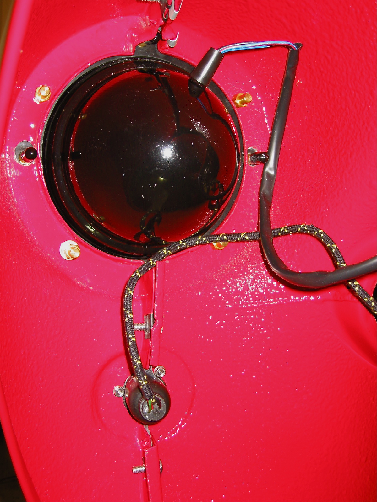
Headlight installed 1
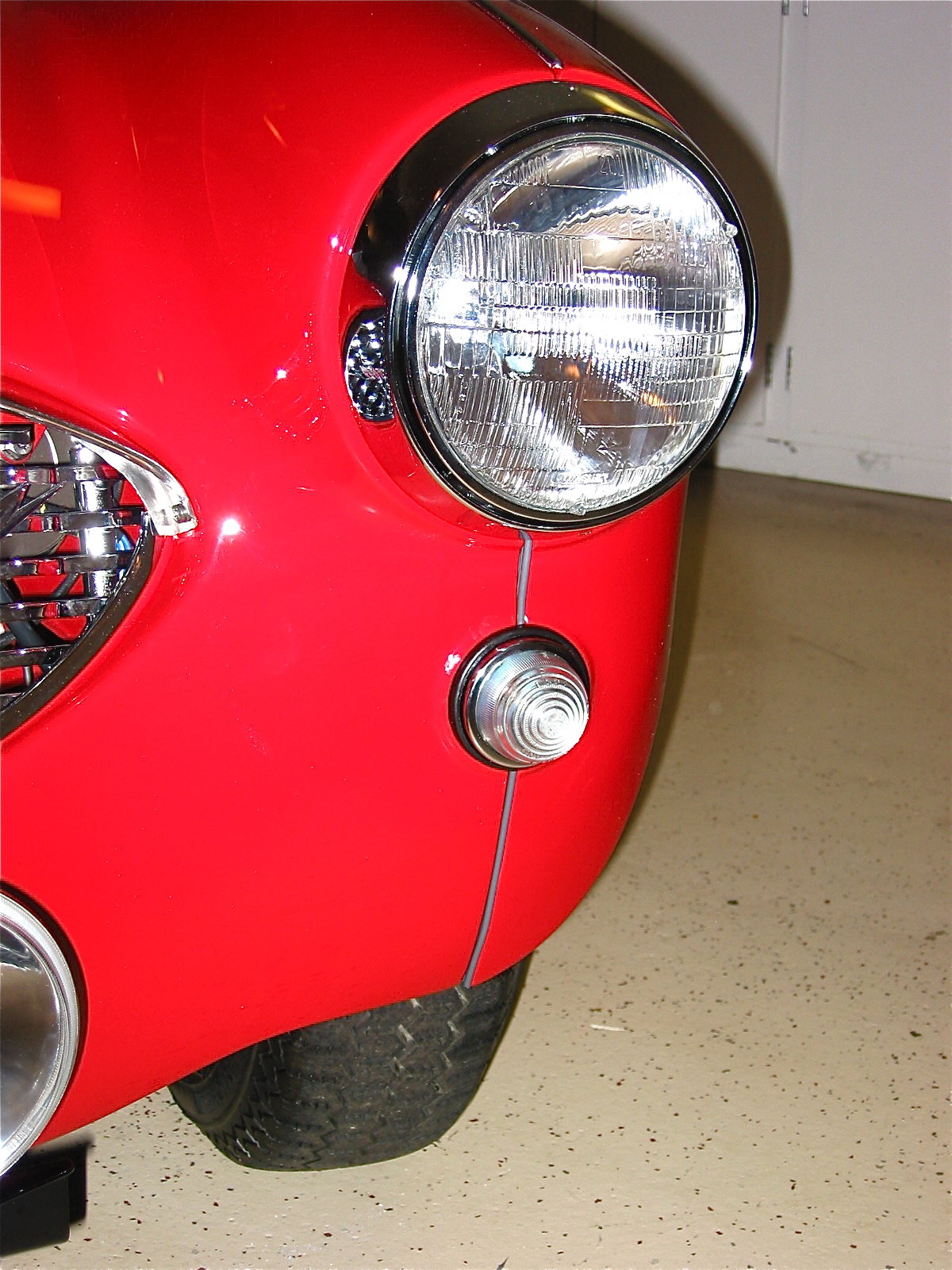
Headlight installed with lower wing beading
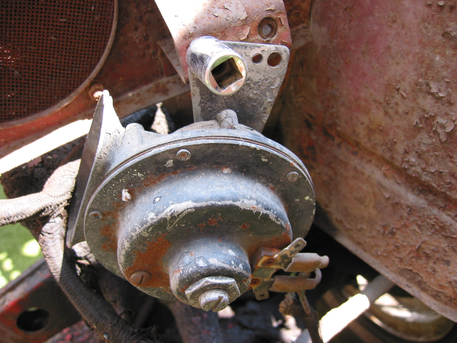
I thought I would check out the fit of the grill and immediately noticed that the horns were preventing the grill from sliding into place. I did not have the original horns and I am using later replacements (these are deeper). I ended up switching the LH and RH units and placing them inside their mounting bracket and this seemed to give me the space I needed for the grill. At some point I would love to find the proper horns!
Horn installed
Now it was on to the tow hook/driving light bracket from Cape International. I bolted the brackets into place and fit the Lucas 570 SLR- 5” driving lights, attached the wiring and tested the lights to find them working beautifully. I had previously installed the light relay, an indicator light and the wiring so that the lights only come on when the bright beams are used.
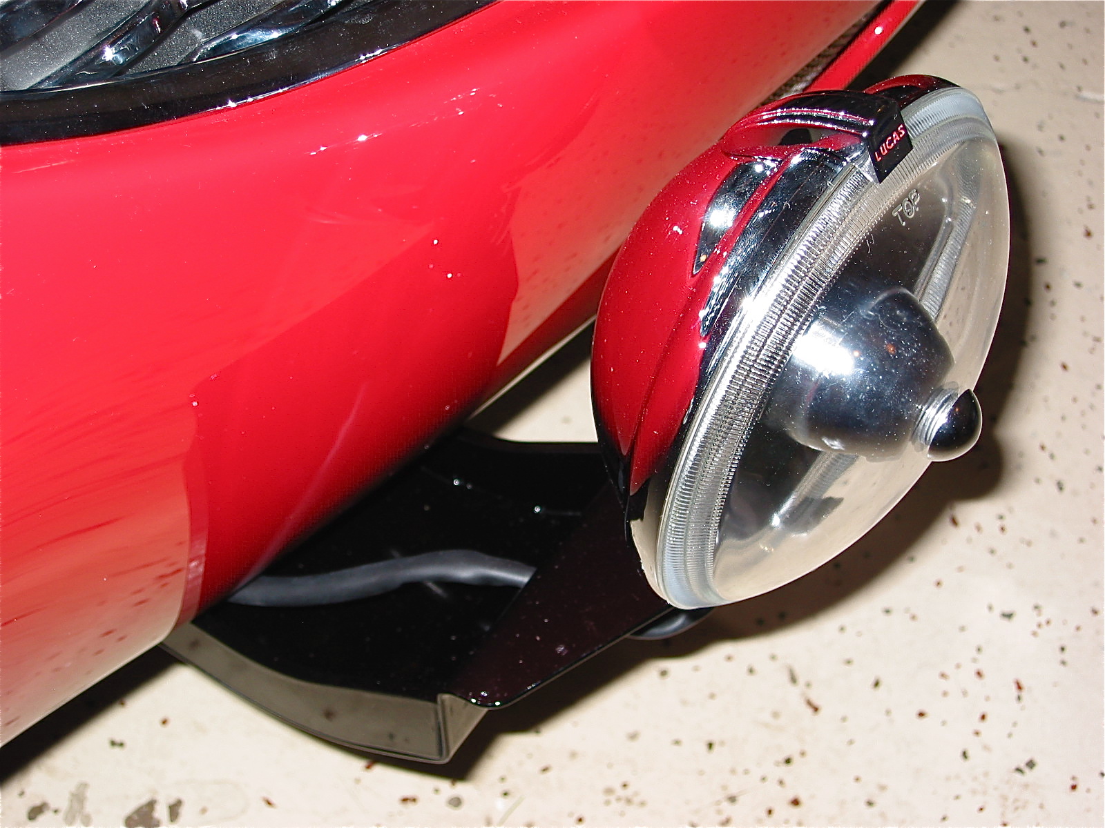
Auxiliary Driving light bracket and tow hook
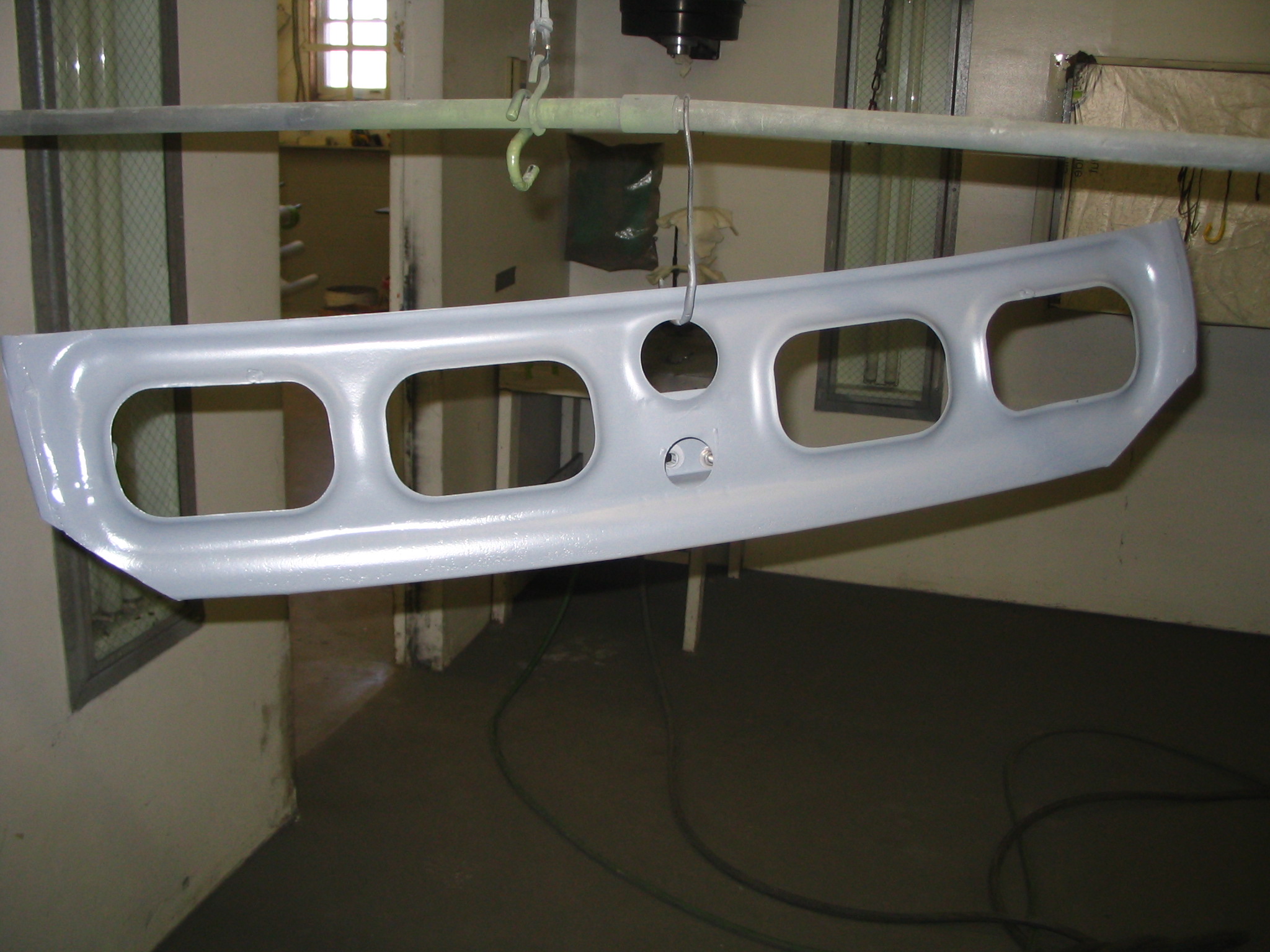
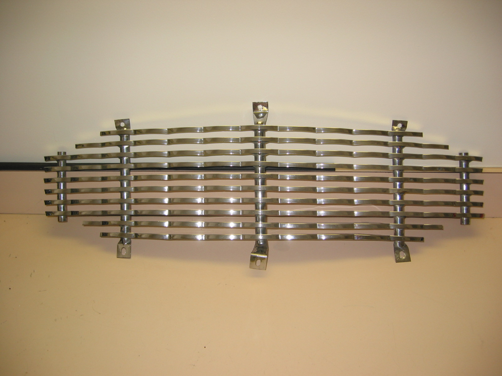
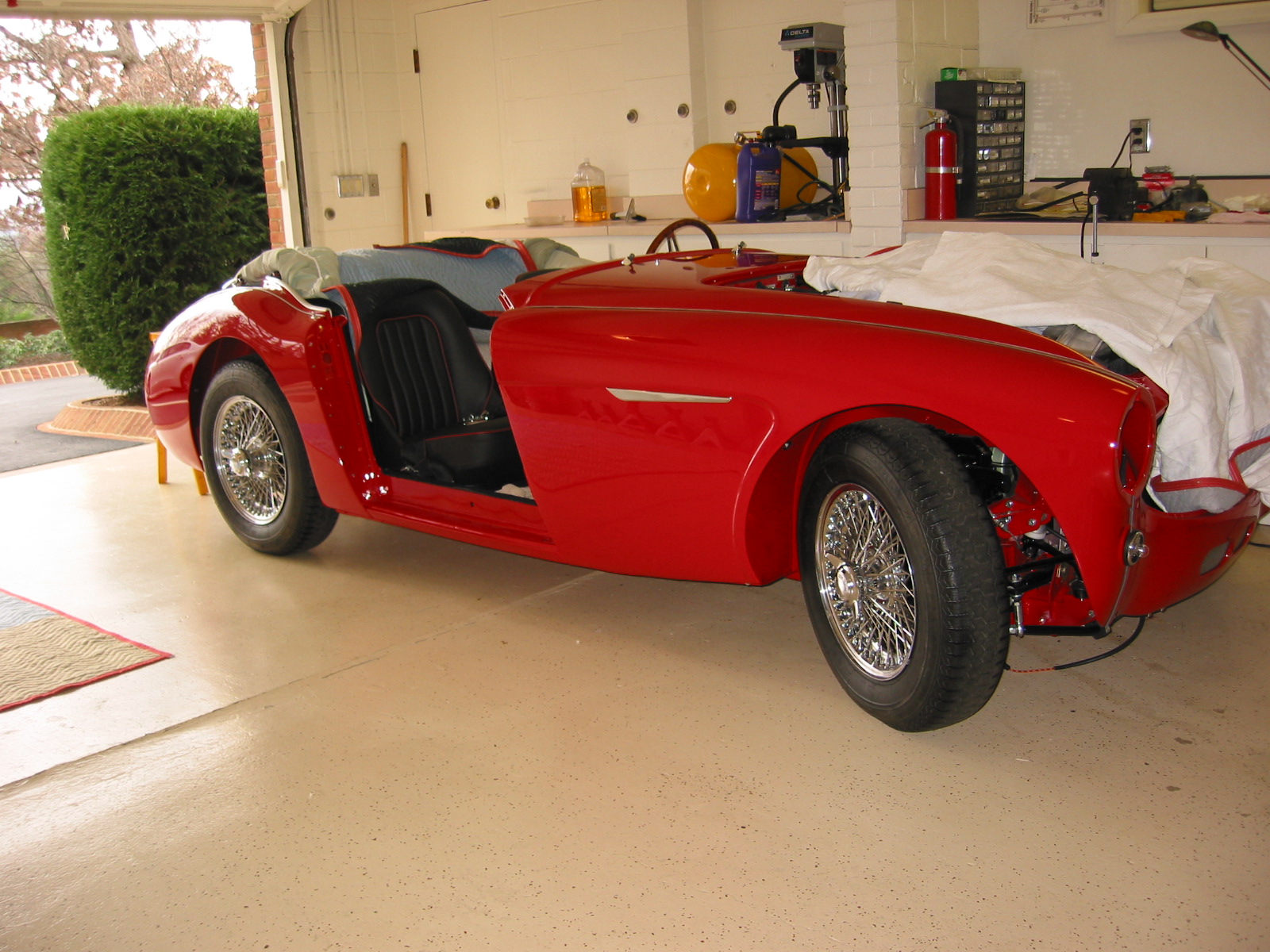
My final work for the week was the installation of the three pieces that comprise the front grille. These were fixed to the car without any issue. The splash panel brackets on either side of the car were fastened to the outside grille mounting brackets.
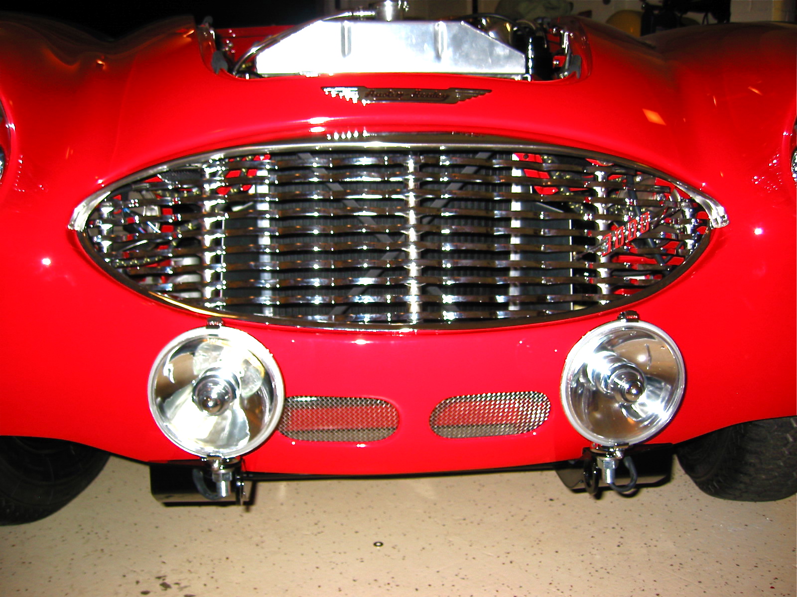
Grille and Lights installed

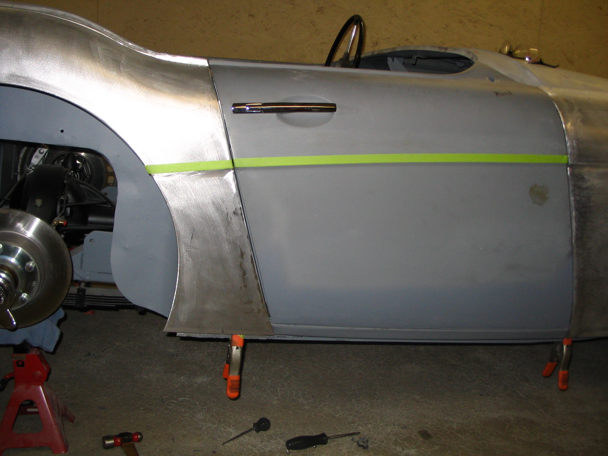
Side View with both wings and door