Dash and Custom Wiring Harness – Part 2

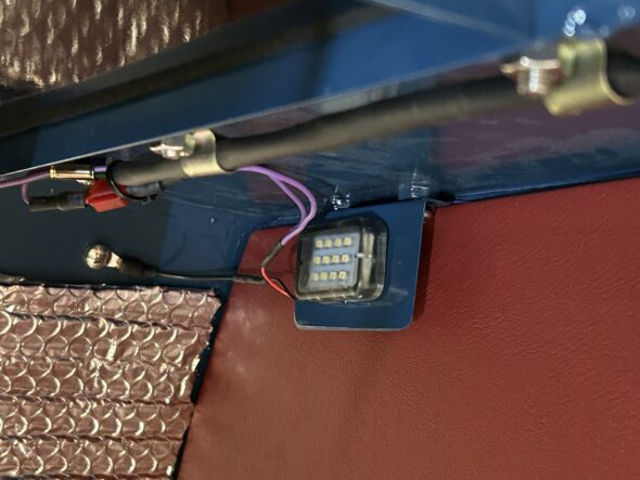
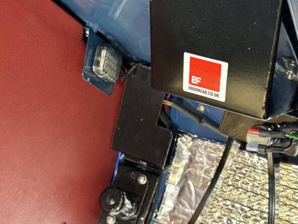
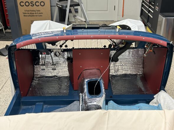
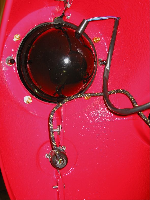
Before installing the dash we wanted to complete the installation of the front courtesy lights as they are not easy to access without the dash, much less with dash in place. We also completed the wiring and testing for the pedal brake switch that can also be seen in the photo below.

LH front courtesy light

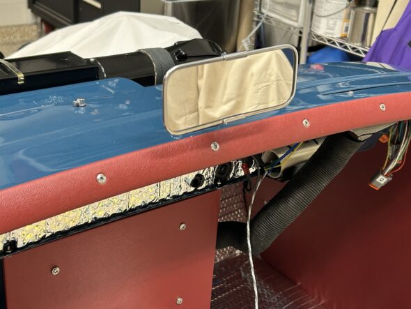
We then covered the front aluminum cockpit molding with our red vinyl and installed it on the body. It looks quite handsome.

front cockpit molding vinyl covered

Just to add a touch of bling to our work the chrome rear view mirror went on next. Two chrome oval head #10-32 x 5/8″ machine screws secure the mirror to the captured nuts in the body.

Rear View Mirror

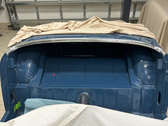
We then added the rear cockpit molding:

Rear cockpit molding

We then installed the LH demister hose to the elbow and nozzle vent. We will be using an AFR gauge to assist with tuning but do not plan to leave it in the car permanently so we ran a red wire from fuse position #19 in our fuse box, through the firewall an into the interior. This wire can be easily removed after we finish tuning.

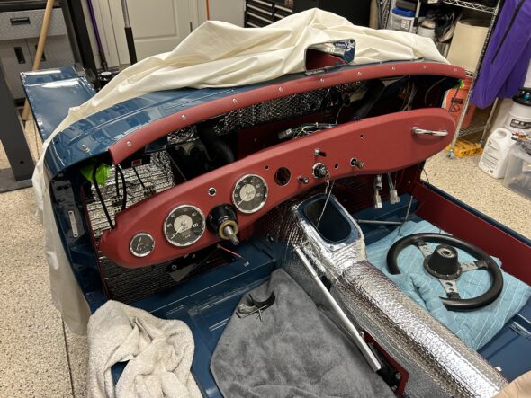
We then began the actual installation of the dash with all of its wiring, gauges, switches and etc. in place. We had seen a tip on the internet to make this task easier. That is to use large zip ties to support the corners of the dash. This allows easy access from above for mating Deutsch connectors, finishing up with a few loose wires and for running cables through the dash and the firewall. As it turned out, it was a great tip and made the job quite a bit easier than it might have otherwise been.

Dash with zip ties to the body

We could then gradually tighten the zip ties and move the dash closer to the body. Ultimately, we cut the zip ties and inserted the 1/4″-28 – 1″ hex head bolts and tightened each corner.

Care must be taken with three items 1. one must keep an eye on the steering shaft so that it remains free in the column bezel. 2. There are two braces under the dash that secure the dash to the firewall. The braces must be above the lip that they mount to on the firewall before the dash to body bolts go in on the corners, otherwise they are difficult to properly position. This is especially true in our case since the braces serve as the platform for our supplementary switch panel behind the dash. 3. Routing the capillary tube for the water temperature gauge and the copper pipe for the oil pressure must be approached cautiously to avoid damage to either.

The installation of the individual items associated with the dash is covered in the attached video. Once we had the dash in place we began testing all of our circuits. Everything seems to functioning properly! A major achievement in the process toward assembling the Bugeye.

Bugeye Restoration Video Episode Eighty-six:

https://vimeo.com/1006256130/a0a01395e3?share=copy

0:00 – Front courtesy lights connected

0:21 – Brake light wiring

1:11 – Covering and installing the aluminum cockpit molding

2:56 – Rear view mirror installed

3:18 – Rear cockpit molding installed

3:50 – LH demister hose installed

4:00 – Temporary AFR gauge wiring installed

4:22- Dash wiring and installation

8:00 – Zip tying the dash to the car

8:47 – Wiper controller rheostat installed

9:07 – Water temperature & oil pressure gauge & pipes installed

10:00 – Windscreen washer pump hoses and wiring connected

10:19 – Brake wiring connected

10:48 – Started cable installed

11:05 – Heater switch installed & wires connected

11:12 – Choke cable installed

11:24 – RH ground bus bar wiring

11:39 – Dash to body mounting bolts and braces

12:08 – Electrical circuit testing begins


Chapter 84 Week Fifty-Four December 24, 2007

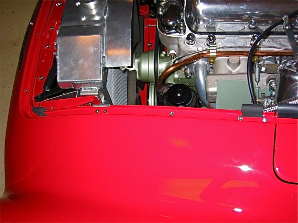
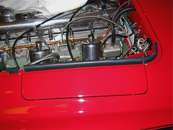
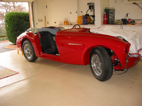
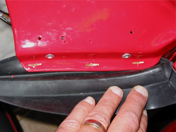
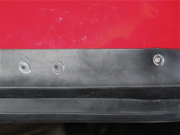
Today (Monday) is Christmas Eve and there is much to be done, so only a little Healey work will happen on this day, but I had a good week. I did manage to install the rubber buffers on the front shroud sill bonnet opening. Three on the left side and two in the right plus the long strip to protect the carbs from the weather. My long strip is cut into two pieces to account for the carb access panel. The buffers are held in place by copper-colored split rivets and flat washersthat are pushed through the mounting hole and then bent over.

LH Rubber Buffers

RH Rubber Buffers 2

LH Carb Panel Seal

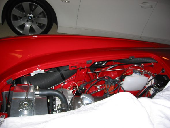
The next task was to fit the front wings to the superstructure. I began with the RH wing, thinking it would be the more difficult of the two. First, I tapped the wing clip nuts onto the wings. Three shorter nuts and bolts are used for the front of the wing, below the headlights. With the help of my wife, who held the wing in place, I installed the rearmost and forward most bolts.

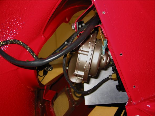
With those two holding the wing in position, I then began to install the other bolts working from the front to the rear. Each one was hand tightened enough to get them started, but with enough room to install the wing beading. The fourth nut/bolt from the front requires Houdini to install. I finally accomplished it after loosening each of the four bolts securing the heater blower and then disconnecting the large fresh air hose from the blower. With the hose loose I was able to access the bolt for the fourth hole.

RH Front Wing 1

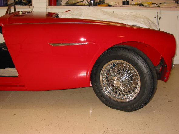
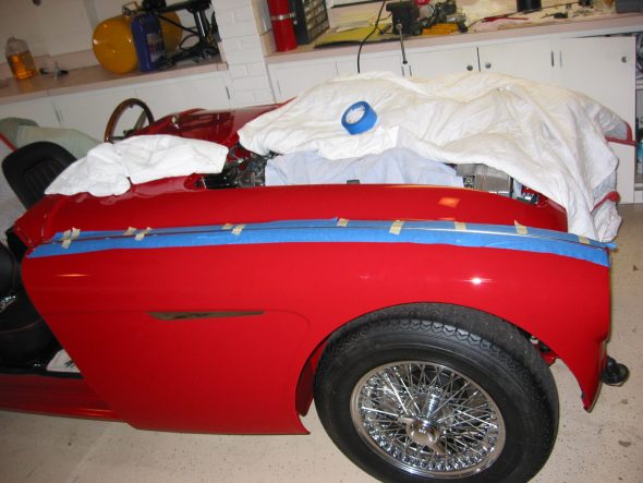
RH Side with front wing

To protect the paint while installing the beading, I ran a strip of painter’s masking tape on the shroud and the wing parallel to the beading.

Beading Installation

After carefully spreading the beading folding tabs so that they were evenly distributed across the wing, I pressed it in place. Once again, four hands come in handy!

With my wife applying downward pressure on the beading I tightened each bolt/nut until the beading was locked in place and the top of the wing was tight.

Then I tackled the three fasteners below the headlight. These are much easier to access. Again, I loosely attached each of the three and then inserted the two plastic beading pieces between the panels and tightened down.

Next were the three 1/4” x 3/4” long hex head bolts used to secure the bottom edge of the wing. Finally, the 3/8” sheet metal screws were used to fasten the wing flanges to the hinge pillar plate. The heater blower fresh air hose was reinstalled and the blower’s four mounting bolts tightened. A little red touch-up paint on the lower bolts and pillar screw heads and then it was on to the LH wing. NEXT TIME I WOULD WAIT TO FASTEN THE WING AT THE BOTTOM UNITL THE DOOR IS INSTALLED. THERE IS FLEX IN THE WING AND BY MOVING IT UP OR DOWN SLIGHTLY ONE CAN BETTER MATCH UP THE WING CURVATURE WITH THAT OF THE DOOR!

The LH wing was a little easier to install in my case because of the carb access panelI had cut into the shroud! The difficult nuts/bolts on the LH wing were the rearmost two because the wiper motor restricts access to the locating holes and hardware.

It was a good feeling to have all four of the body’s wings in place.

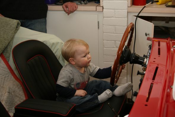
The next task was the installation of the scuttle seals that I had ordered from Bill Bolton. These are reputed to the best available, and the fit does seem to be quite nice. As I was working on the seals and dash pad I had a visit from grandson #2, Shane. As the image shows, he seemed right at home in the Bloody Beast.

Little Shane’s visit to the Garage

Little Shane’s Visit

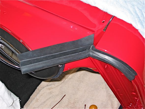
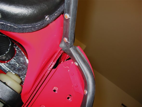
Fitting the scuttle seals was not as difficult as I expected. The job was made much easier by following directions: Scuttle Seal Install Rich Chrysler along with those provided by Bill Bolton.

Scuttle seal 1

Scuttle seal rivets 1

scuttle seal screw holes

Scuttle seal rivets 2

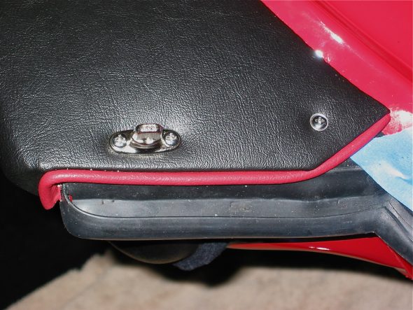
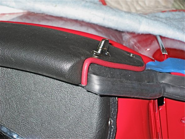
I then installed the dash pad, along with the hot air outlet defroster masks, the mirror, tonneau turnbuckles, and the stud for the tonneau cover.

Dash Pad seal 1

Dash Pad seal 2

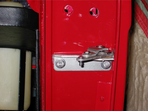
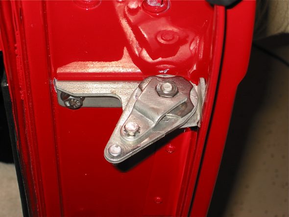
Once the dash and accompanying hardware was installed I was ready to begin the door installation. I first attached the door check strap assembly to each side. Then I taped all the edges of the wings, sills and doors with painter’s masking tape for protection.

Check Strap Assembly 2

Check Strap Assembly 3

My son John (23 years of age and strong) lifted the doors in place and I ran in the door hinge screws. This job was actually easier and less time intensive than I imagined. Of course, I still need to adjust them for proper fit. I had previously attached all the door interior upholstery, trim and hardware which was much easier than installing it all on the car, but it did make the doors quite heavy.

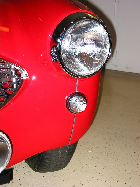
Next on my list was the installation of the headlight buckets, headlight bulbs, and the chrome lens retaining rim. It wasn’t necessary, but I jacked up the front of the car and temporarily removed the splash shields and the tires to give easier access to the rear of the headlight buckets. I experienced a little difficulty with mounting the trim rim but eventually got it to lock into place. Then I secured the parking/flasher light assemblies to the car with the three small machine screws and nuts, and put the clear lens in place.
Headlight installed 1

Headlight installed with lower wing beading

I thought I would check out the fit of the grill and immediately noticed that the horns were preventing the grill from sliding into place. I did not have the original horns and I am using later replacements (these are deeper). I ended up switching the LH and RH units and placing them inside their mounting bracket and this seemed to give me the space I needed for the grill. At some point I would love to find the proper horns!

Horn installed

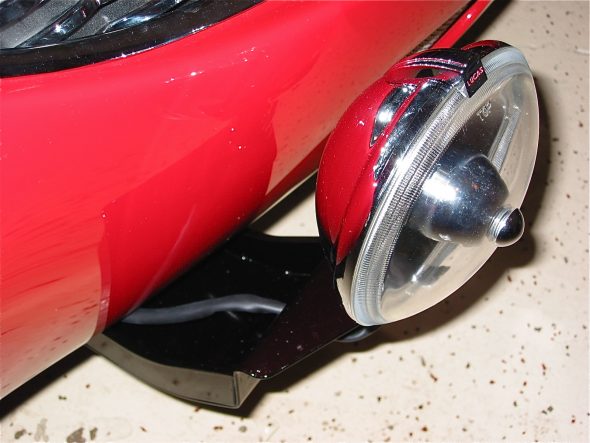
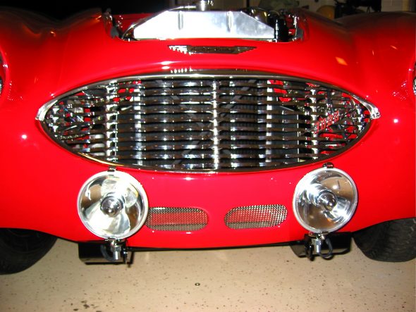
Now it was on to the tow hook/driving light bracket from Cape International. I bolted the brackets into place and fit the Lucas 570 SLR- 5” driving lights, attached the wiring and tested the lights to find them working beautifully. I had previously installed the light relay, an indicator light and the wiring so that the lights only come on when the bright beams are used.

Auxiliary Driving light bracket and tow hook

My final work for the week was the installation of the three pieces that comprise the front grille. These were fixed to the car without any issue. The splash panel brackets on either side of the car were fastened to the outside grille mounting brackets.

Grille and Lights installed

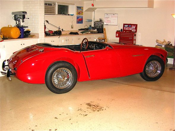
Side View with both wings and door

Interior

Rear View Mirror

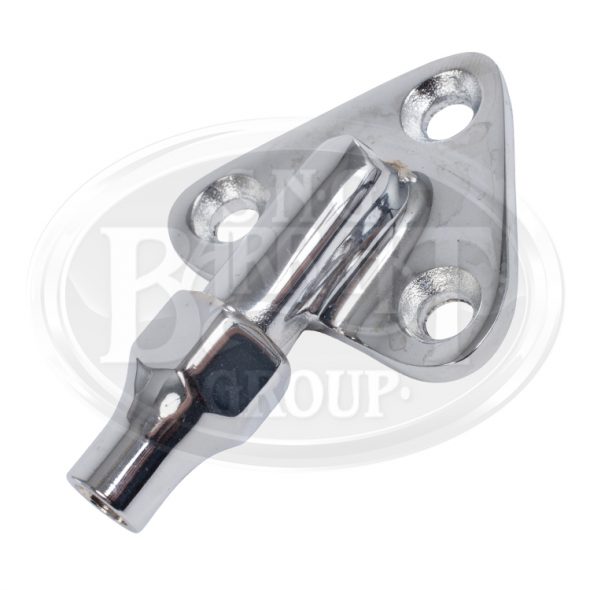
The parts manual does not provide much information on the rear view mirror. The assembly apparently came from Lucas and was installed as an assembly. Perhaps there is Lucas documentation available someplace, but I did not find it. My original mirror was pretty dirty and the height adjustment post would not tighten properly. A new mirror assembly is available from SNG Barratt, but I decided to use my original. I did purchase a new “Interior Mirror Mounting Clamp/Boss – C20697/1”, that addressed my sliding adjustment problem:

Mirror Mounting Clamp/Boss

Mirror Mounting Clamp/Boss

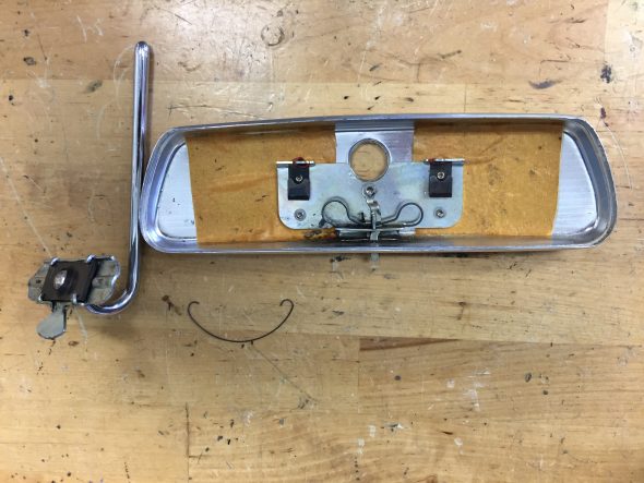
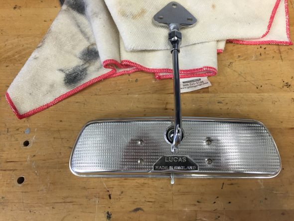
I also had my original mirror re-silvered by Tim Inman at Inman Historic Interiors www.historicinteriors.com/Resilvering.html The resilvering costs about $65 including shipping. The finished product looked like new. Reassembly is pretty easy but it does require carefully bending four tabs that secure the tensioning spring for the mirror ball joint. The image below shows the mirror casing and the spring assembly with adjustable post.

Rearview Mirror Before Assembly

Rearview Mirror Before Assembly

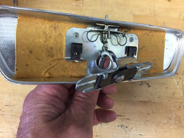
The image below show the installation of the post and tensioner spring with mounting plate:

Installing Rearview Mirror Components

Installing Rearview Mirror Components

The image below shows the tensioner spring plate tabs bent back to secure the spring plate:

Tensioner Spring Tabs bent into Position

Tensioner Spring Tabs bent into Position

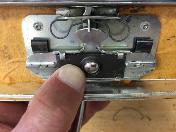
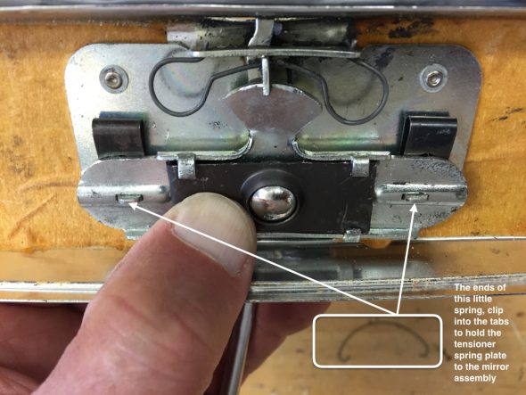
A very fine sprung wire holds the tensioner plate to the mirror assembly as seen in this image:

Rear View Mirror Retaining Spring

Rear View Mirror Retaining Spring

The mirror casing cleaned up with some polish and hand buffing:

Polished Mirror Casing

Polished Mirror Casing

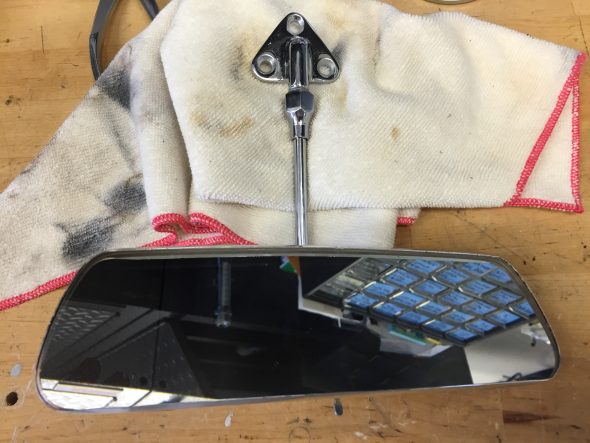
The final step was popping the mirror back into the casing to complete the job!

Resilvered Mirror Installed

Resilvered Mirror Installed

Of course, the generous use of Walnut veneered wood and supple leather hides make a Jaguar!

Wood Trim

I will have all of the wood professionally refinished. possible vendors include:

http://www.classicdashboards.com/gallery-jaguar-restoration-photos.html

Classic Dashboards is operated by Simon Lorkin who is located in France.

British Autowood operated by Saul Chaplin is in Altamonte Springs, Florida: http://www.britishautowood.com/index.htm


Leather Trim

I have not yet decided if I will have the leather and vinyl work custom stitched or if I will go with one of the primary suppliers:

John Skinner at: http://www.jaguar-trim.co.uk

or,

BAS Ltd. at: http://www.basjaguartrim.com/mk2daimler250.htm

or,

Aldridge Trimming at: http://www.aldridge.co.uk