Dash and Custom Wiring Harness – Part 2

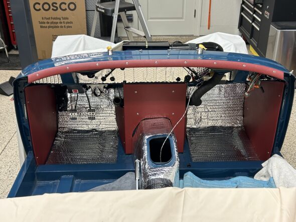
Before installing the dash we wanted to complete the installation of the front courtesy lights as they are not easy to access without the dash, much less with dash in place. We also completed the wiring and testing for the pedal brake switch that can also be seen in the photo below.

LH front courtesy light

We then covered the front aluminum cockpit molding with our red vinyl and installed it on the body. It looks quite handsome.

front cockpit molding vinyl covered

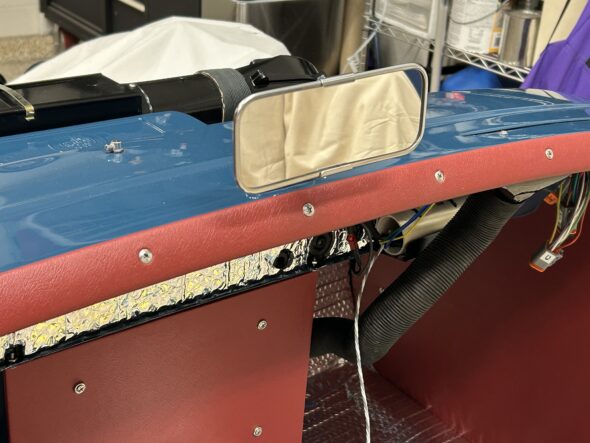
Just to add a touch of bling to our work the chrome rear view mirror went on next. Two chrome oval head #10-32 x 5/8″ machine screws secure the mirror to the captured nuts in the body.

Rear View Mirror

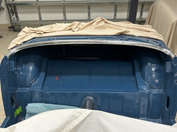
We then added the rear cockpit molding:

Rear cockpit molding

We then installed the LH demister hose to the elbow and nozzle vent. We will be using an AFR gauge to assist with tuning but do not plan to leave it in the car permanently so we ran a red wire from fuse position #19 in our fuse box, through the firewall an into the interior. This wire can be easily removed after we finish tuning.

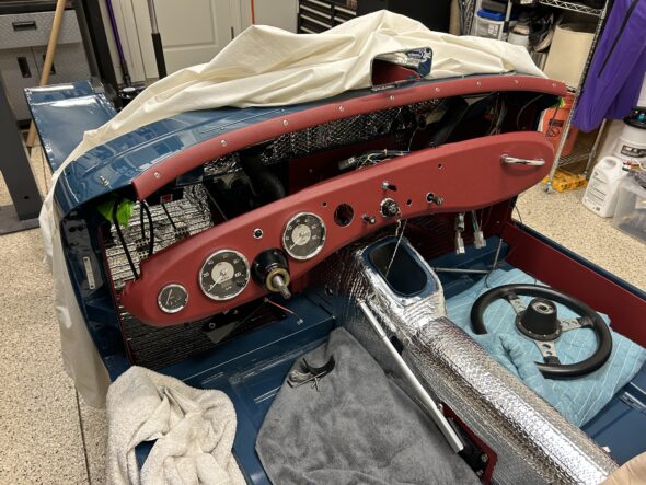
We then began the actual installation of the dash with all of its wiring, gauges, switches and etc. in place. We had seen a tip on the internet to make this task easier. That is to use large zip ties to support the corners of the dash. This allows easy access from above for mating Deutsch connectors, finishing up with a few loose wires and for running cables through the dash and the firewall. As it turned out, it was a great tip and made the job quite a bit easier than it might have otherwise been.

Dash with zip ties to the body

We could then gradually tighten the zip ties and move the dash closer to the body. Ultimately, we cut the zip ties and inserted the 1/4″-28 – 1″ hex head bolts and tightened each corner.

Care must be taken with three items 1. one must keep an eye on the steering shaft so that it remains free in the column bezel. 2. There are two braces under the dash that secure the dash to the firewall. The braces must be above the lip that they mount to on the firewall before the dash to body bolts go in on the corners, otherwise they are difficult to properly position. This is especially true in our case since the braces serve as the platform for our supplementary switch panel behind the dash. 3. Routing the capillary tube for the water temperature gauge and the copper pipe for the oil pressure must be approached cautiously to avoid damage to either.

The installation of the individual items associated with the dash is covered in the attached video. Once we had the dash in place we began testing all of our circuits. Everything seems to functioning properly! A major achievement in the process toward assembling the Bugeye.

Bugeye Restoration Video Episode Eighty-six:

https://vimeo.com/1006256130/a0a01395e3?share=copy

0:00 – Front courtesy lights connected

0:21 – Brake light wiring

1:11 – Covering and installing the aluminum cockpit molding

2:56 – Rear view mirror installed

3:18 – Rear cockpit molding installed

3:50 – LH demister hose installed

4:00 – Temporary AFR gauge wiring installed

4:22- Dash wiring and installation

8:00 – Zip tying the dash to the car

8:47 – Wiper controller rheostat installed

9:07 – Water temperature & oil pressure gauge & pipes installed

10:00 – Windscreen washer pump hoses and wiring connected

10:19 – Brake wiring connected

10:48 – Started cable installed

11:05 – Heater switch installed & wires connected

11:12 – Choke cable installed

11:24 – RH ground bus bar wiring

11:39 – Dash to body mounting bolts and braces

12:08 – Electrical circuit testing begins


Wiring to the rear of the car

We completed the wiring harness for the central part of the car and to the bonnet before the Bugeye went for paint. Now that the car is home we are able to finish up the wiring to the rear so that we can send the harness components off to Rhode Island Wiring to have them wrap the harnesses in cloth braid.

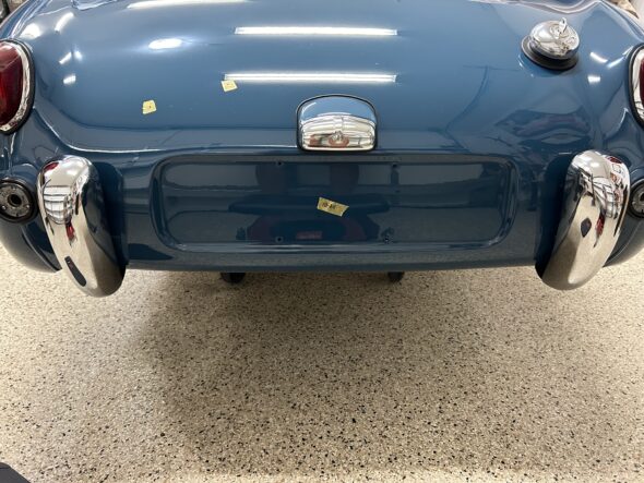
Crawling into the inside rear of a Bugeye, or “hole” as I refer to it, is no easy task. It is best handled by a nimble young contortionist – not by a 6′ 1″ seventy-two year old! Wiring the tail lights with brake lights, flashers and side lights, the license plate lamp, the fuel level sender, the fuel pumps and rear courtesy lights required many a trip into the depths of the “hole.”

The rear flashers require the installation of spire nuts to the body. We purchased some new ones and mounted them.

Rear Flashers Spire Nuts

The original Sprite MK I had a mechanical fuel pump but with the onset of later Sprites, and the 1275 engine, the design was modified to incorporate a rear mounted electric pump. In our case, we mounted the SU pump as it would have been secured in the later Sprites, but we also added in series a redundant low-pressure Facet pump with a dash mounted switch enabling the driver to switch between the two pumps as desired. The center position on the switch disconnects power to both pumps providing a form of anti-theft deterrent.

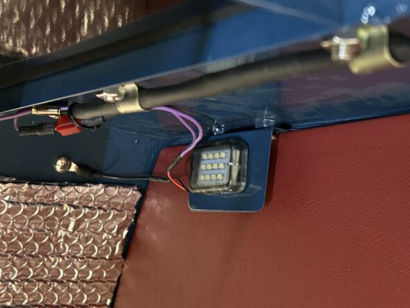
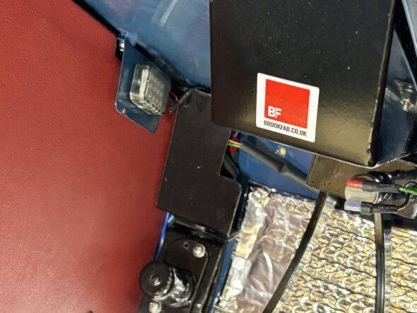
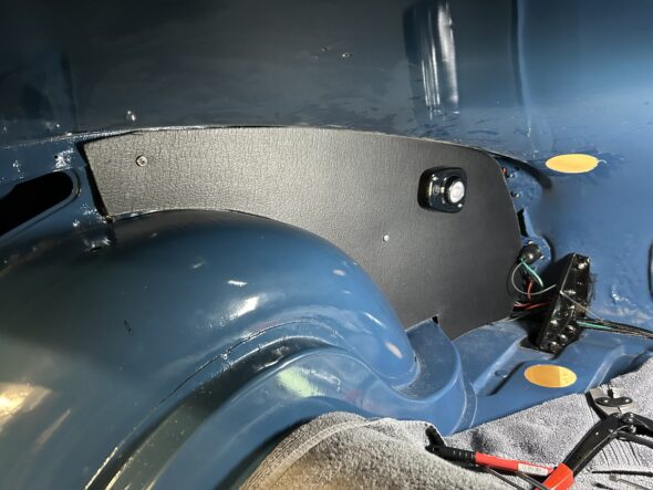
We fit the rear courtesy lights to each of the rear boot trim panels. We purchased the panels from Bugeyeguys.com. They required considerable trimming to fit them to the car, but once achieved we were able to mount the lights and complete the necessary wiring. The panels will eventually be covered in a red vinyl that matches the other interior panels.

Rear Trim Panels and Courtesy Lights

In the rear we resorted to using rubber covered bullet connectors for a number of fittings. This was done because it is hard to reach into the back of the car and if it became necessary to separate wires for one reason or another it is easier to accomplish with the bullet connectors as opposed to the Deutsch connectors. Since weather isn’t an issue in the boot we should not experience any problems with the bullet connectors.

Once we established our wire lengths and connections we pulled the harness out of the car to send off to have them braided in black with the signature baby-blue tracer used in the Sprite. Originally, all of the wires to the rear of the car were bundled in one braided wire package and routed to the rear under the door sill and rear trim panels. Because we added wires to the mix we decided to bundle the wires into two four-wire groups to run in parallel under the panels. Hopefully this will cause the trim panels to protrude less and yield a nicer finished product.

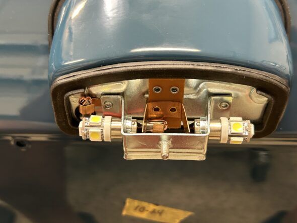
Bugeye Restoration Video Episode Seventy-one shows the creation and installation of the electrical wiring in the rear of the car for the exterior lights, interior courtesy lights, the fuel pumps, and the fuel sender for the fuel gauge. Fitting of the rear trim panels is also shown.

https://vimeo.com/978445012/5aa017a2ba?share=copy

The following content is found in this video:

0:00 – Wiring for tail lights and flashers

1:24 – Spire nuts for side lights/flashers

1:40 – Wiring the side light/flasher fixtures

2:40 – Chrome trim rings and red beehive glass

3:25 – All rear lights mounted

3:36 – Internal rear lights wiring

4:17 – License plate wiring

5:39 – Dash “F” connector wiring to the rear of the car

6:15 – Bullet connectors for lights wiring

7:54 – Rear courtesy lights and trim panels

12:15 – Fuel pump wiring

14:43 – Facet fuel pump fuel filter

15:00 – Fuel level sender

15:42 – Floor rubber grommet for fuel sender wire

16:00 – Removing wiring to have Rhode Island Wiring braid the harness

16:28 – Taping the wires


Chapter 28 – Cleaning and Trial Fitting

March 28, 2006

Jeremy Turner’s Work Continues

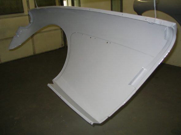
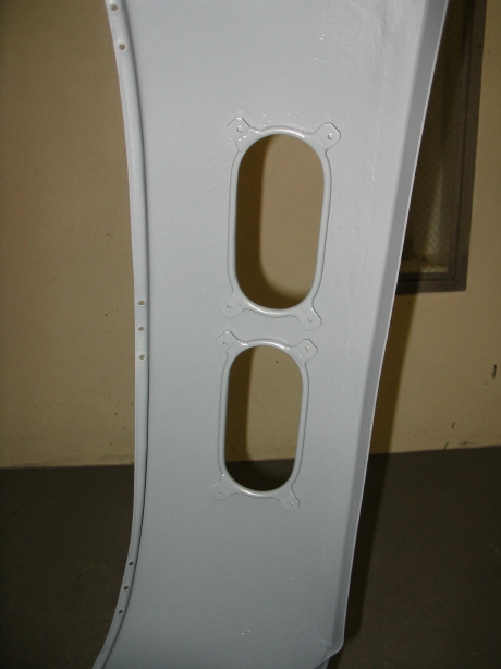
front wing body work 5

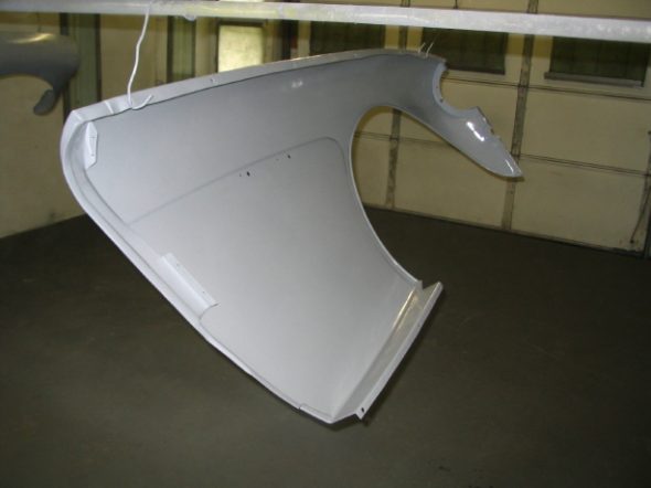
front wing body work 6

Interior and Boot Courtesy Lighting

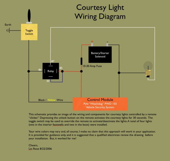
Earlier in the Blog I referenced the installation of courtesy lamps. To avoid switches in the door jams, I purchased a keyless remote. The one I acquired from Pyle was about $40.00. It included two remote “clickers”, the control module, and the wiring. I grossly underutilized all that the Pyle system makes possible, but I was after simplicity. I just cut off all the extra wires, but I can imagine a few other very practical uses. For example, the fuel pump could be wired in and the remote could be used as an anit-theft device by controlling the activation/deactivation of the pump. 

The button on the remote to unlock the car (obviously not needed on a BT7 roadster!) is now pushed to activate the interior/boot lights. As I approach the car at night I can click the remote and my interior and boot lights will come on for about 30-40 seconds and then they extinguish on there own with no other action required. 

I wired in a toggle switch located under the dash (unseen by others) which will overide the remote that I can switch “on” if I want the interior/boot lights to stay on. 

All very simple, clean and unobtrusive. Now if I can just figure out how to disguise that much-to-modern looking remote to look like a british key fob!

Courtesy Light Install

Jeremy Turner’s Work Continues

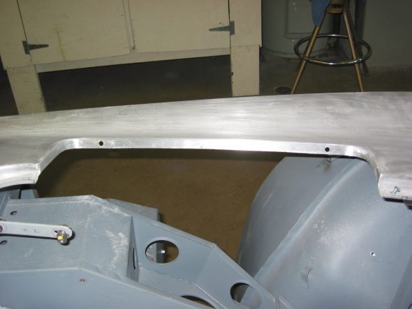
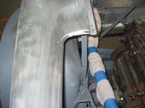
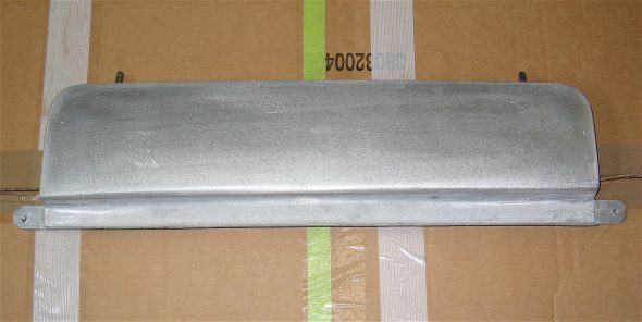
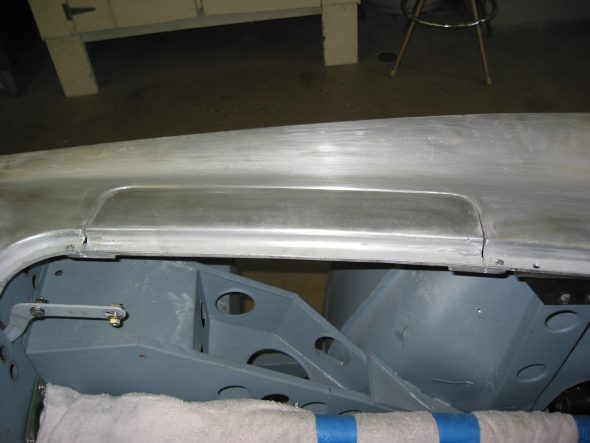
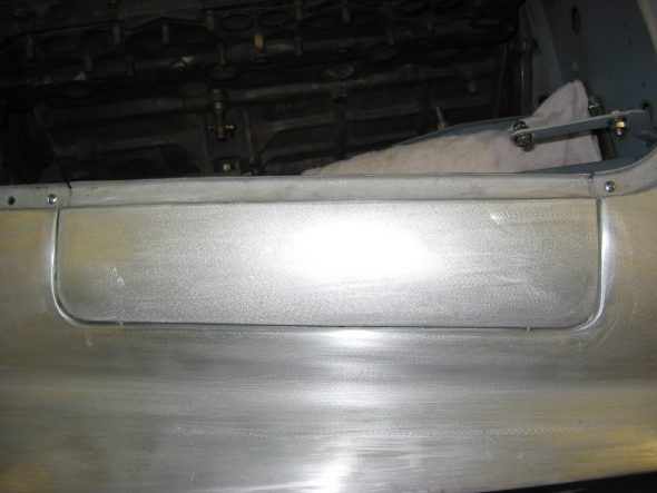
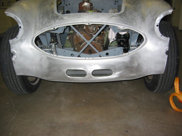
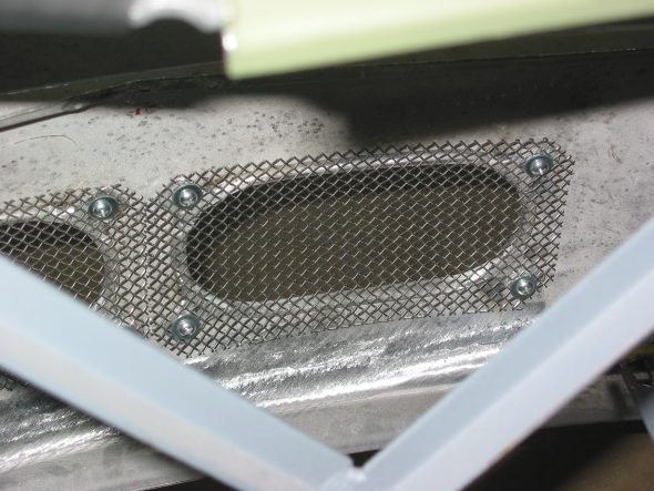
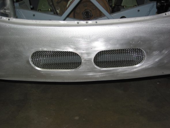
Shroud Modifications – Jeremy called to say that Craig Naff had finished his work and as I had hoped, it was worth the wait! We had asked Craig to cut two oil cooler vents in the the lower valance of the front shroud and to make some repairs in the same area caused by improper towing. In addition, I wanted to create a carb/master cylinder access panel. Unlike the panels you often see on rally cars, I desired something that would appear as original bodywork, fitting flush in the shroud rather than sitting on top. Finally, the rear shroud needed some welding where Martin Jansen has installed new flanges to mount to the rear wings. It turned out the Craig was as good as Jeremy had suggested. I am very pleased with his work.

EDITOR’S UPDATE – April, 2020

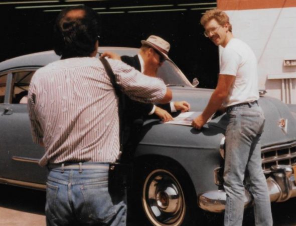
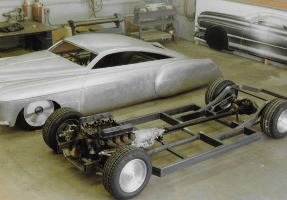
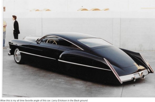
At the time Craig Naff made the modifications to my Healey, I had no idea that he was such an accomplished metal-craftsman with such an impressive portfolio! It is now 2020 and I know that I should have appreciated who was working on my car at the time! Whether he would claim it to be his best work or not I do not know, but his metalwork on Billy Gibbon’s (ZZ Top) 1948 Cadillac is what made him famous. It was about 1989 and Craig was working for Boyd Coddington in California and undertook the job of bringing Larry Erickson’s custom design to life. The world knows the final product as Cadzilla.

Some time later, Craig apparently wasn’t crazy about California life and he returned to his roots in the Valley of Virginia and now has a shop and home outside of Woodstock, VA. Even though I didn’t fully appreciate who Craig was at the time, when Jeremy and I took my Healey to Craig’s shop and I saw the other projects with which he was occupied I did recognize that he was a special talent. Judging by his Facebook Page Craig has stayed busy and is in high demand with a waiting list, but this modest man never boasted about his accomplishments he just turned out outstanding work. Personally, I would consider him to be an artist who happens to work in sheet metal.

Thank you, Craig, for adding your touches to my car!

https://www.caranddriver.com/features/a15132614/the-candy-man/

https://www.customcarchronicle.com/forums/topic/cadzilla-the-craig-naff-files/#.Xpsfzy2ZOd0

Caddy Before Modification with Craig in the White Tee Shirt and Billy Gibbons of ZZ Top in the Hat

Cadzilla before paint

Cadzilla

I concluded some time back that the placement/look of the front vents is all a matter of personal opinion, as long as they accomplish the mission of getting air into the cooler. In my collection of images from cars with vents taken at shows and races, I have seen about as many variaties as there are cars. Craig did hit what I wanted spot-on, so I am pleased. The access panel is, in my opinion, the best arrangement I have seen on any car previously. It will make working on the carbs much easier.

carb access panel 1

carb access panel 2

carb access panel 6

carb access panel 8

carb access panel 7

oil cooler vents 2

oil cooler vents 3

oil cooler vents 1

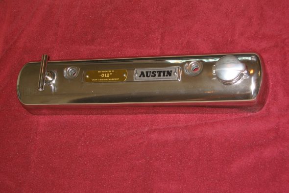
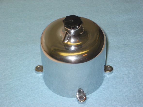
Rocker Cover and Carb Dashpots – The polisher finished his work about the same time the shroud work completed. Again, I was quite pleased with the quality of workmanship.

Capesport Rocker cover Polished

Carb dashpot polished

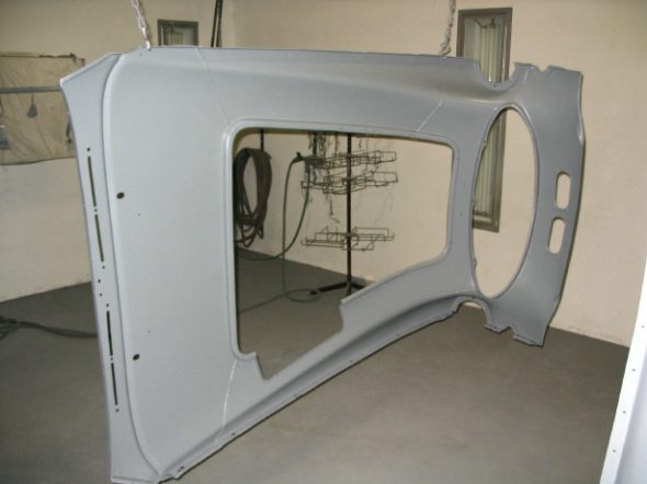
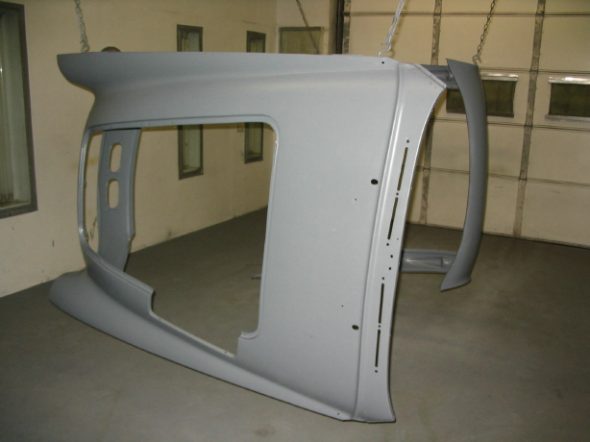
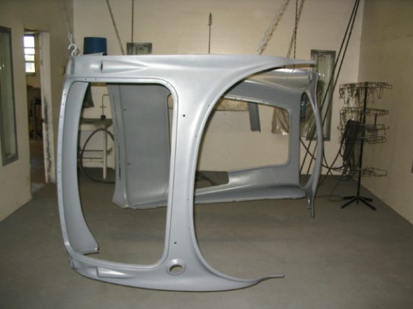
Shroud bodywork – Jeremy made some quick progress on the front shroud after getting it back from Craig. It is great to see some filler and primer on the aluminum!

shrouds primed 2

shrouds primed 3

shrouds primed 4

shrouds primed 1