We connected the rear license plate plinth and light.
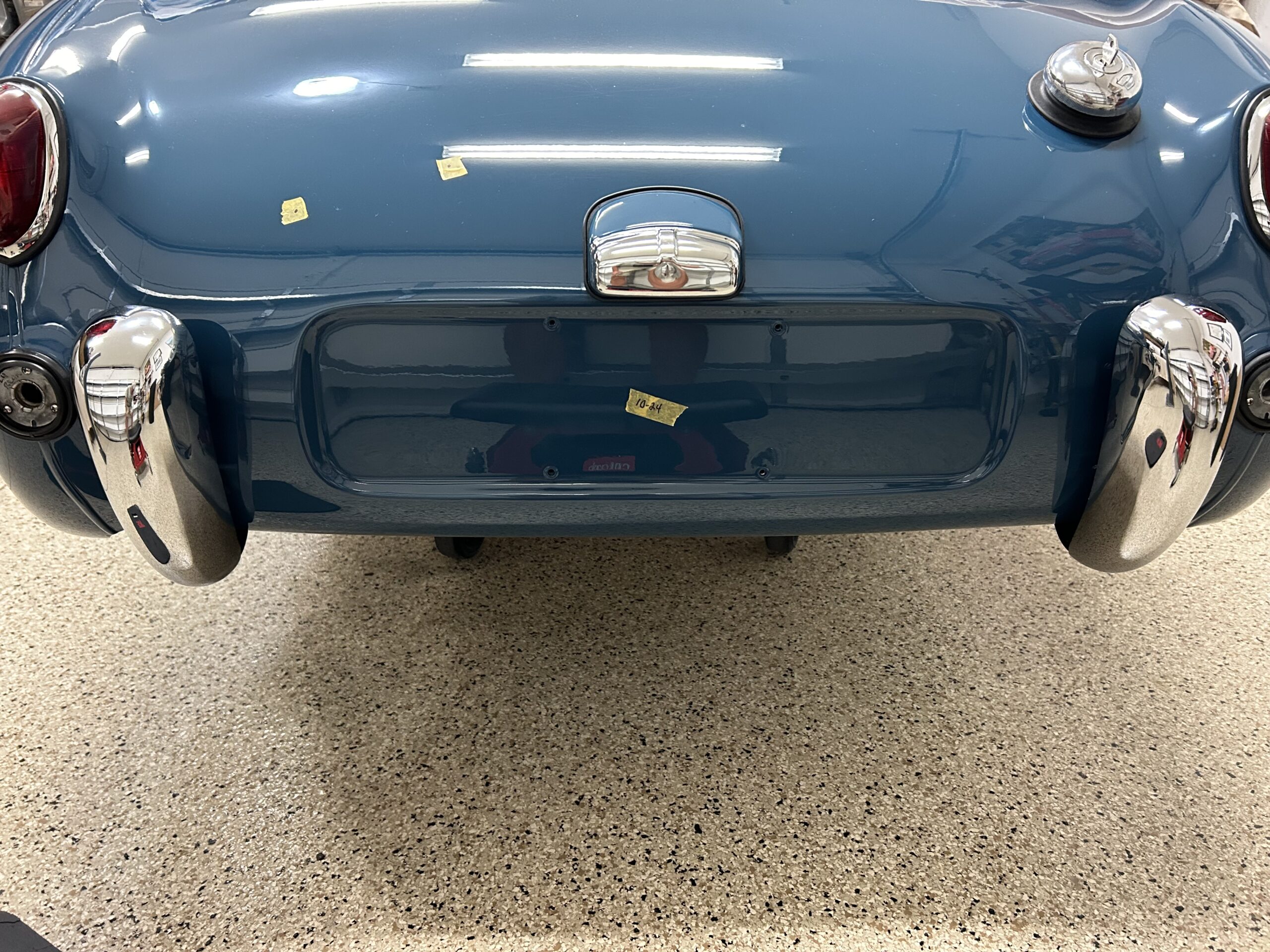
Final Installation of license plat plinth and Light
This procedure is detailed in Bugeye Restoration Video Episode Eighty-five shows the installation process:
https://vimeo.com/1002052489/b28c484815?share=copy
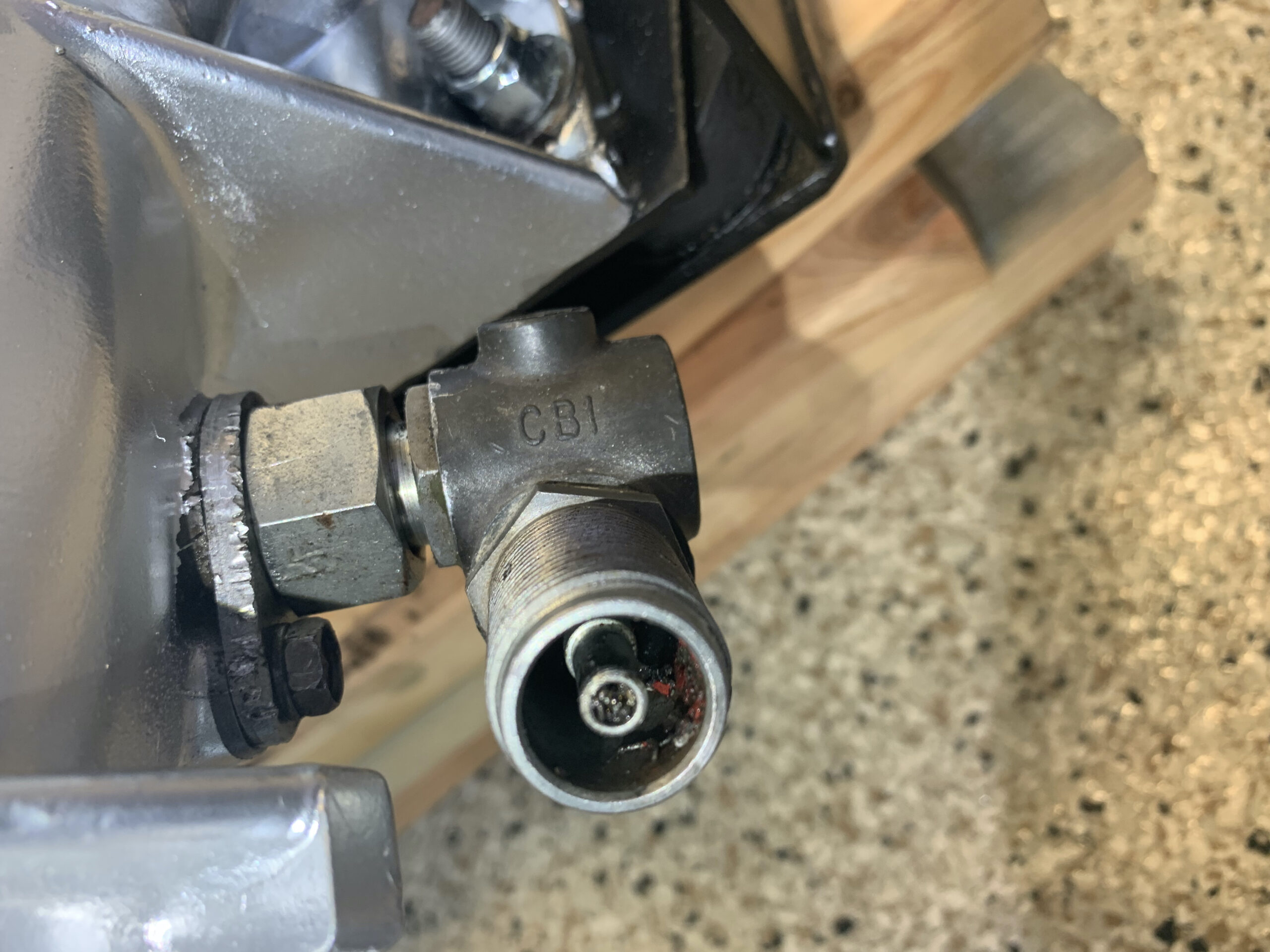
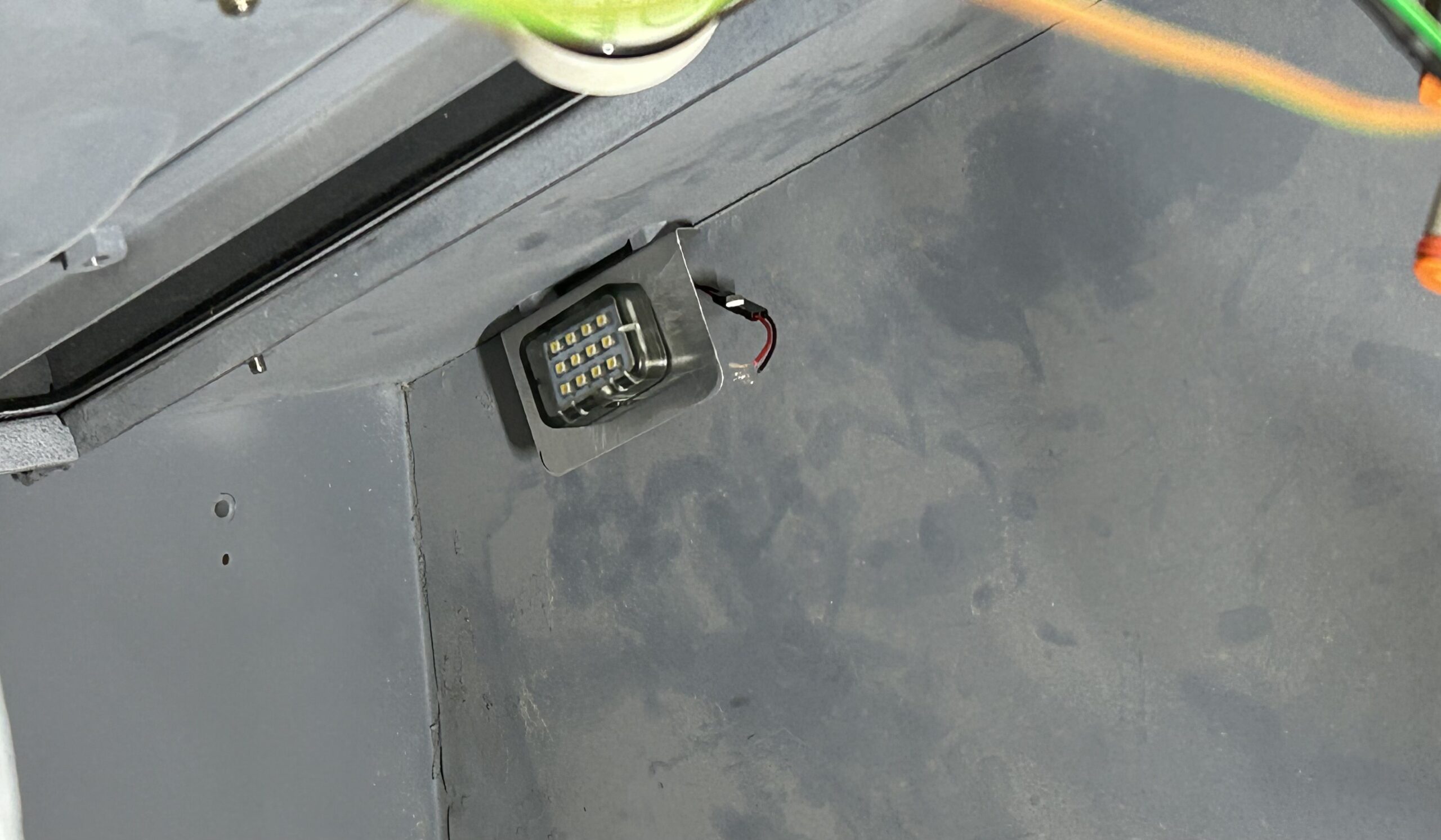
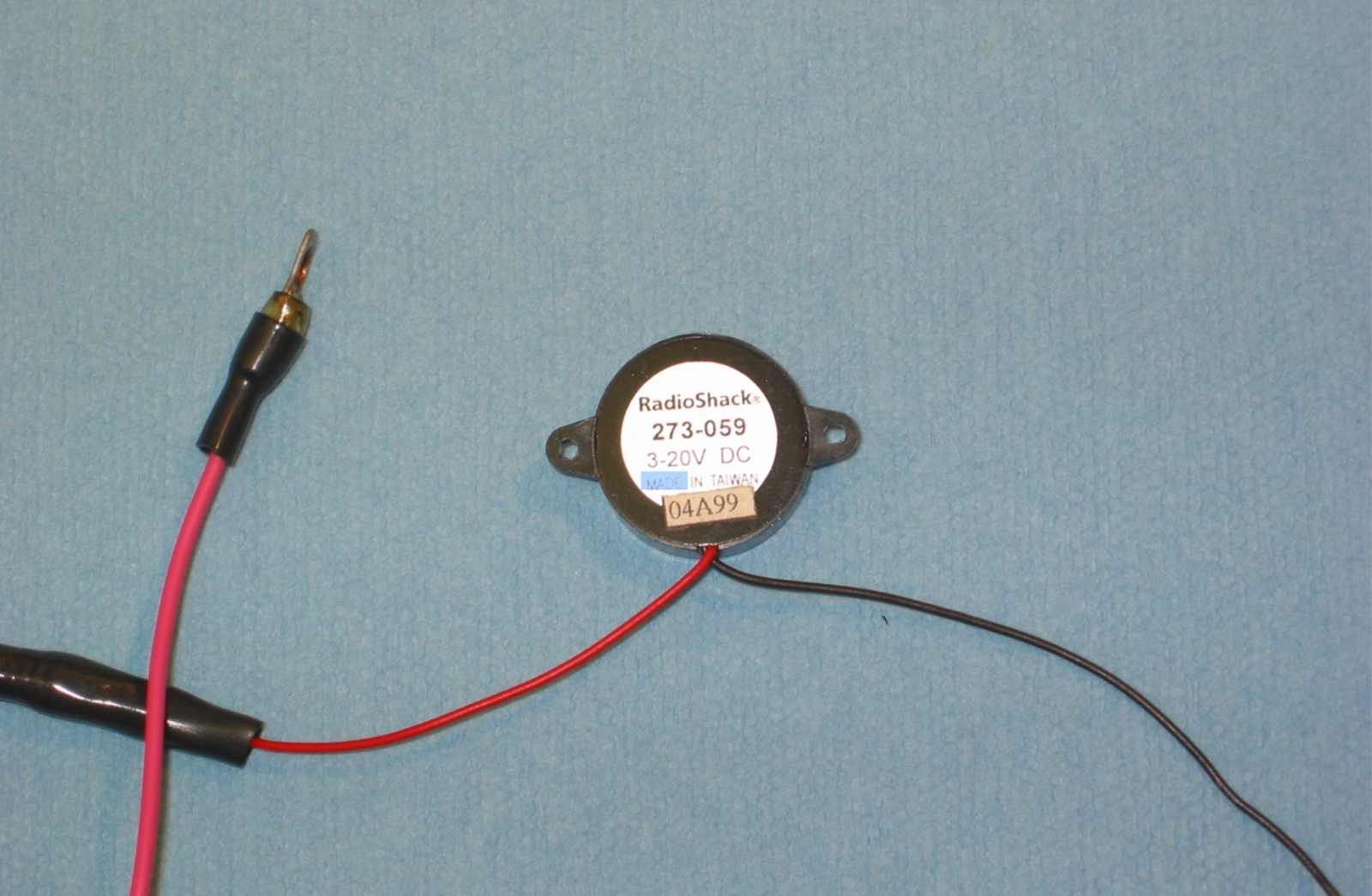
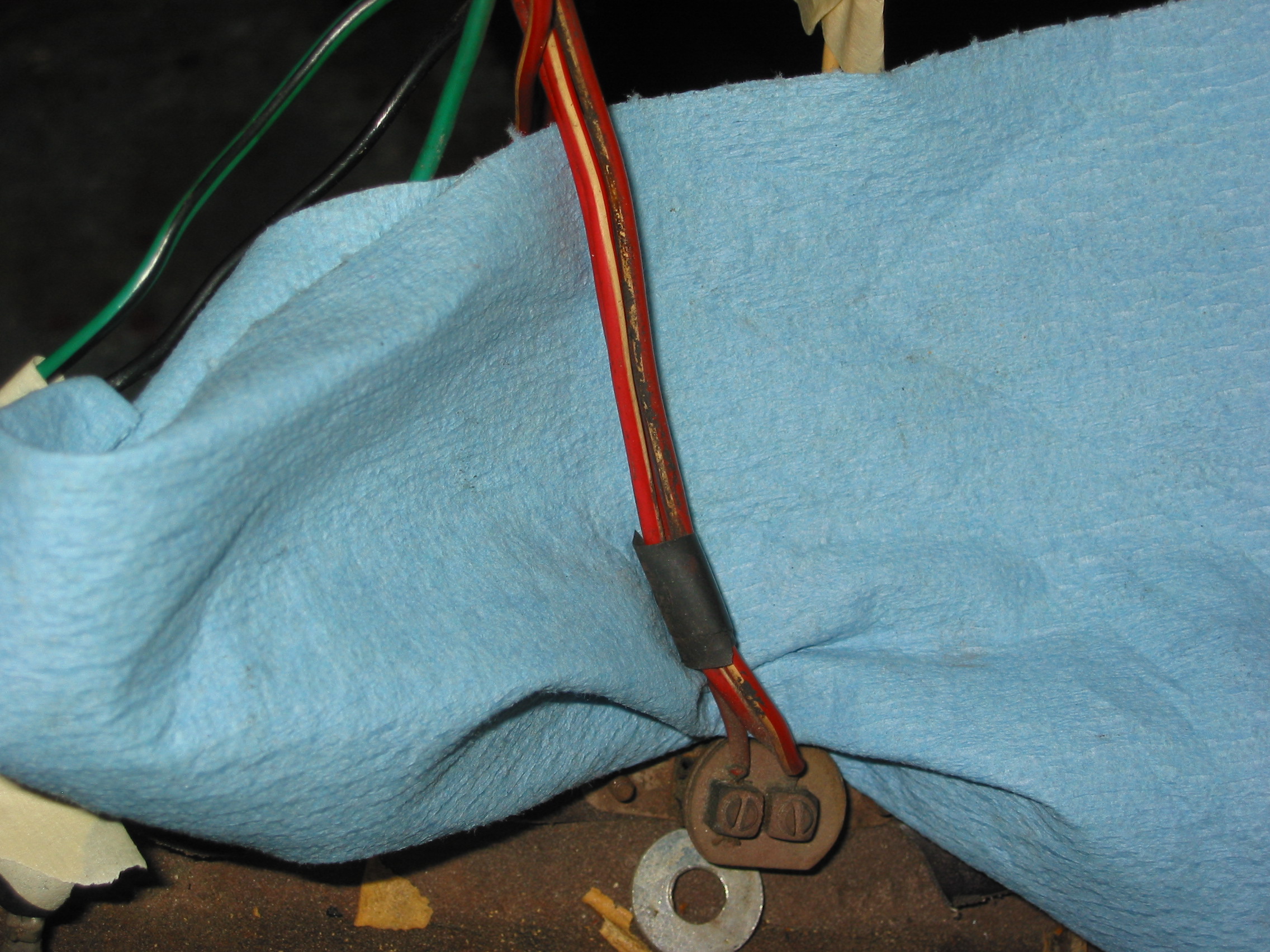
This is just a matter of connecting the black ground wire to the appropriate terminal in the fixture and connecting the red wire to its terminal in the fixture. This is seen in the image below.
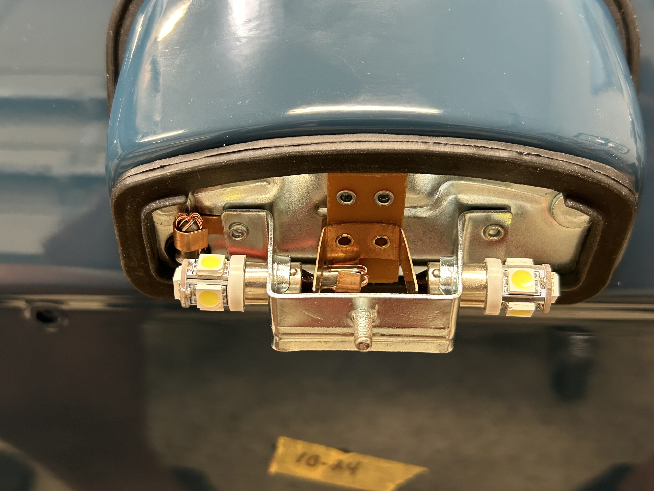
License Plate Light with LEDs
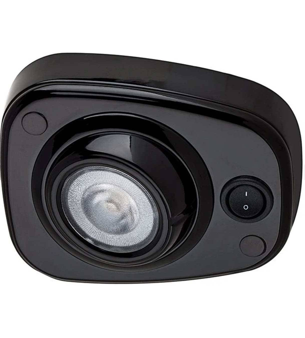
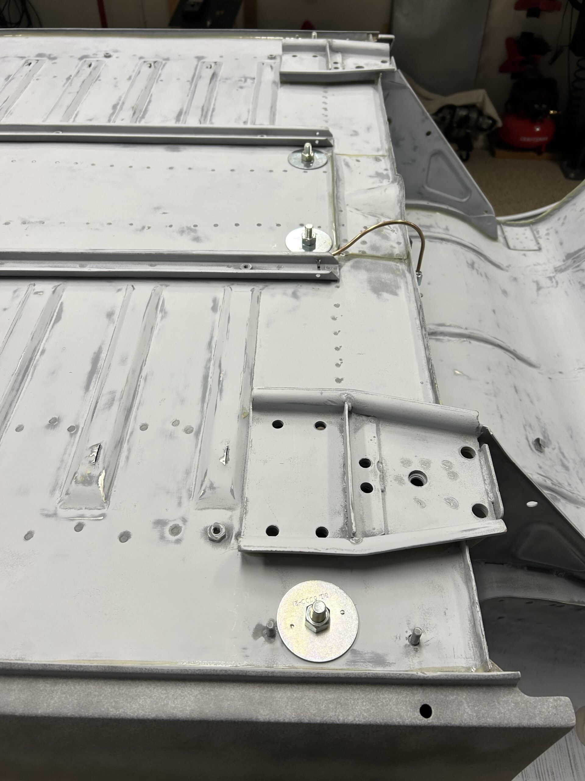
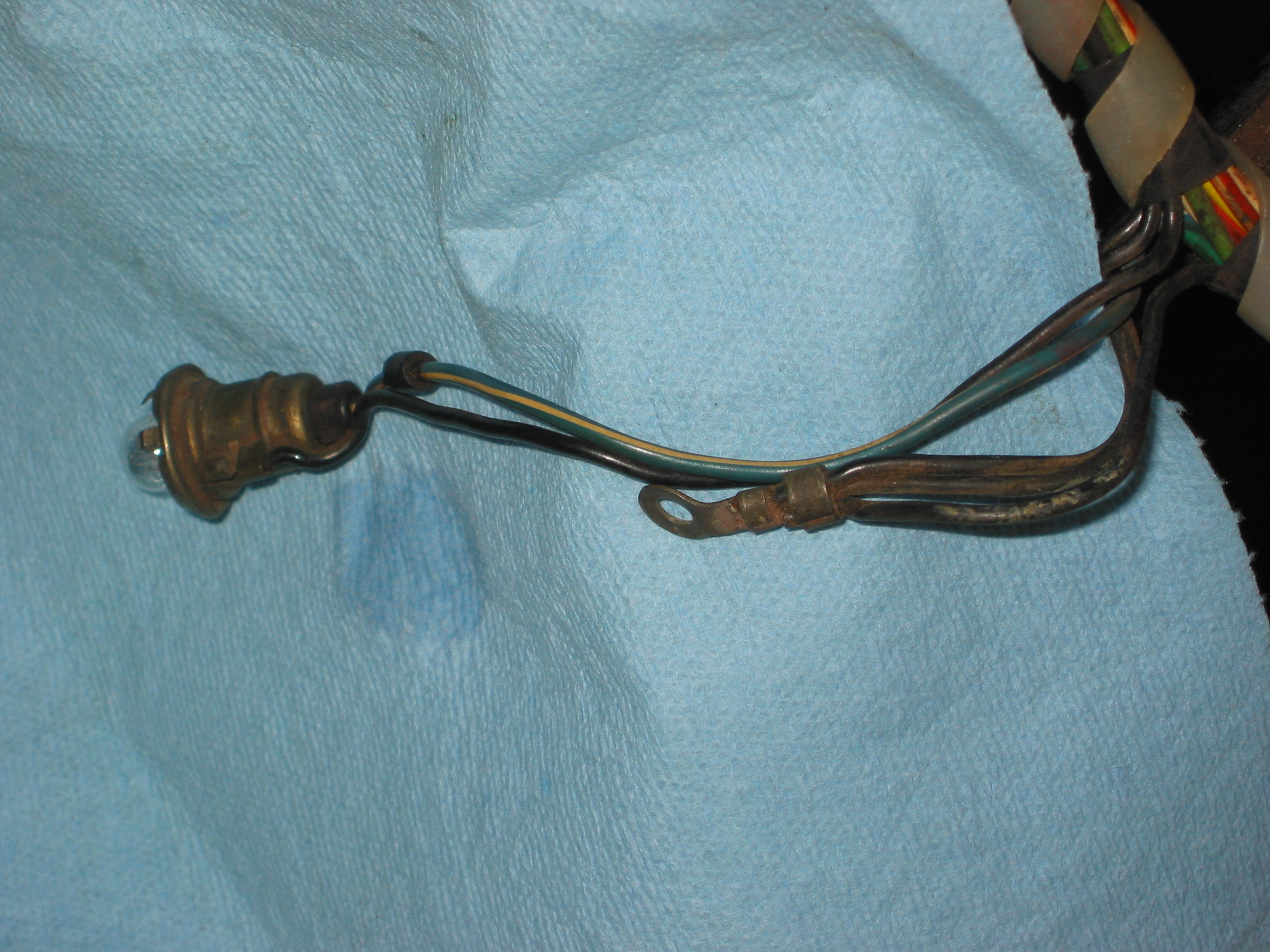
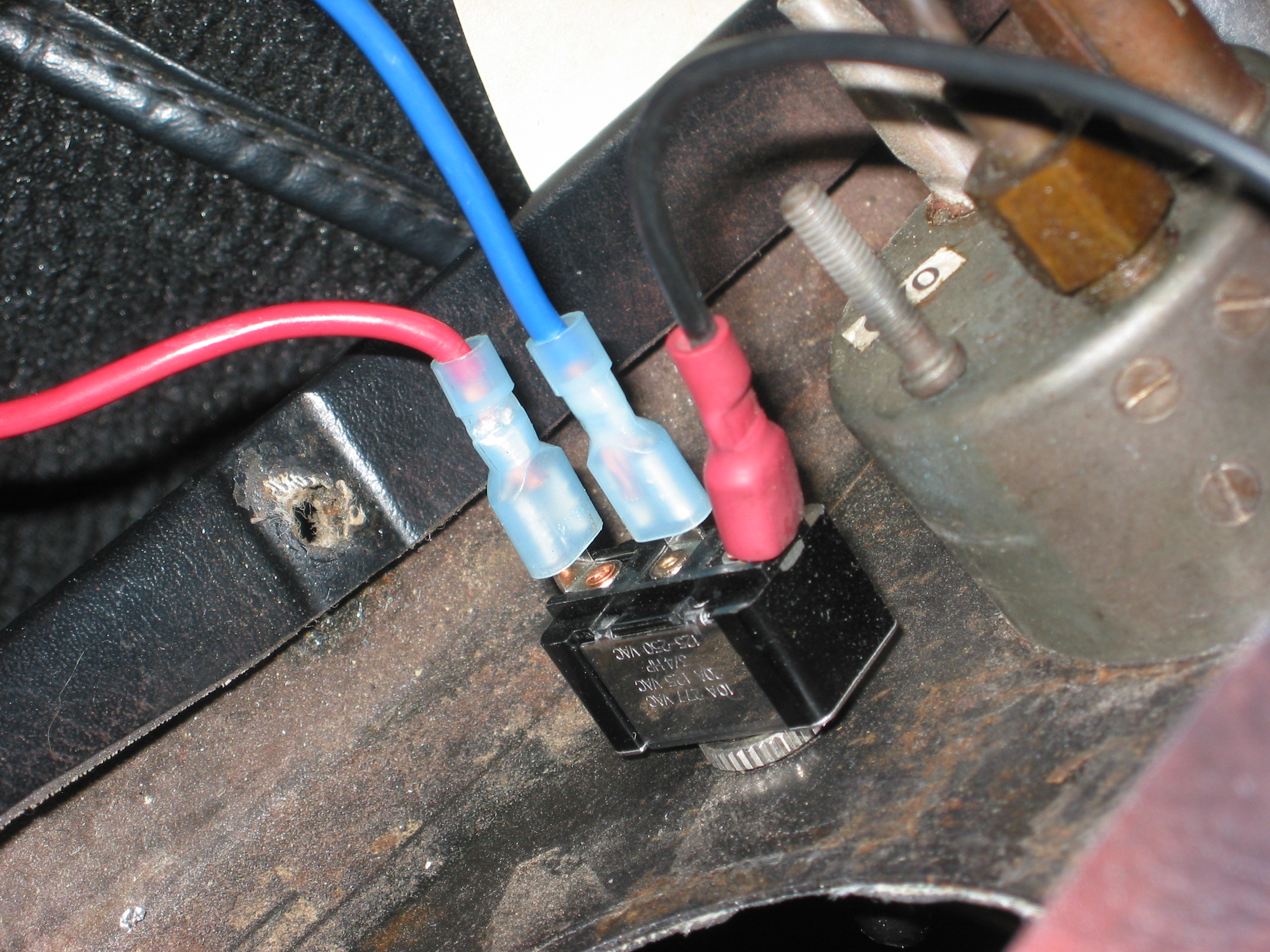
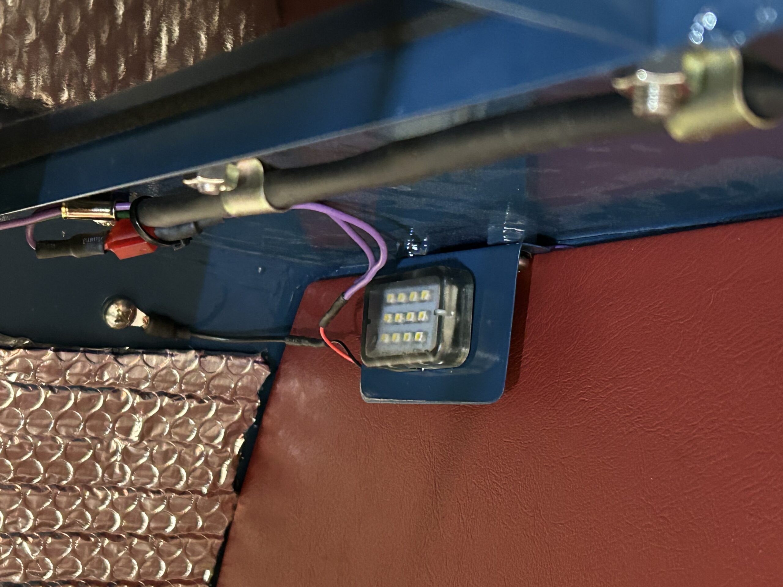
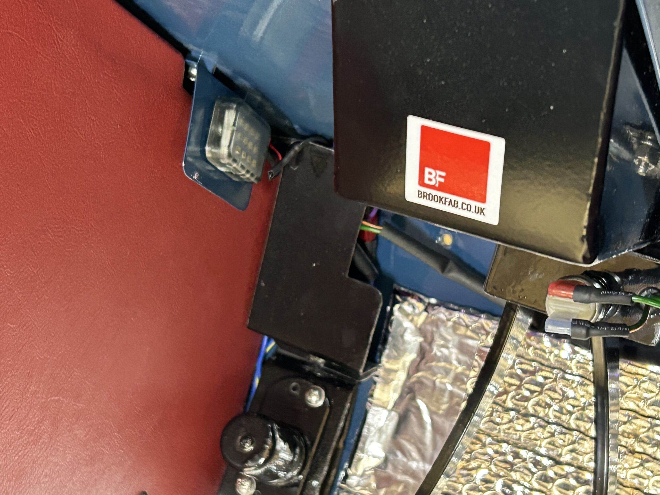
Next we turned to installing the front interior courtesy lights. The front courtesy lights are located in the two footboxes on the outside walls and use the original bonnet prop fixed nuts as mounting points. Small brackets to house the lights were fabricated and painted Cotswold Blue. The lights were sourced from Better Car Lighting in the UK. https://www.bettercarlighting.co.uk/index.php?act=viewProd&productId=171
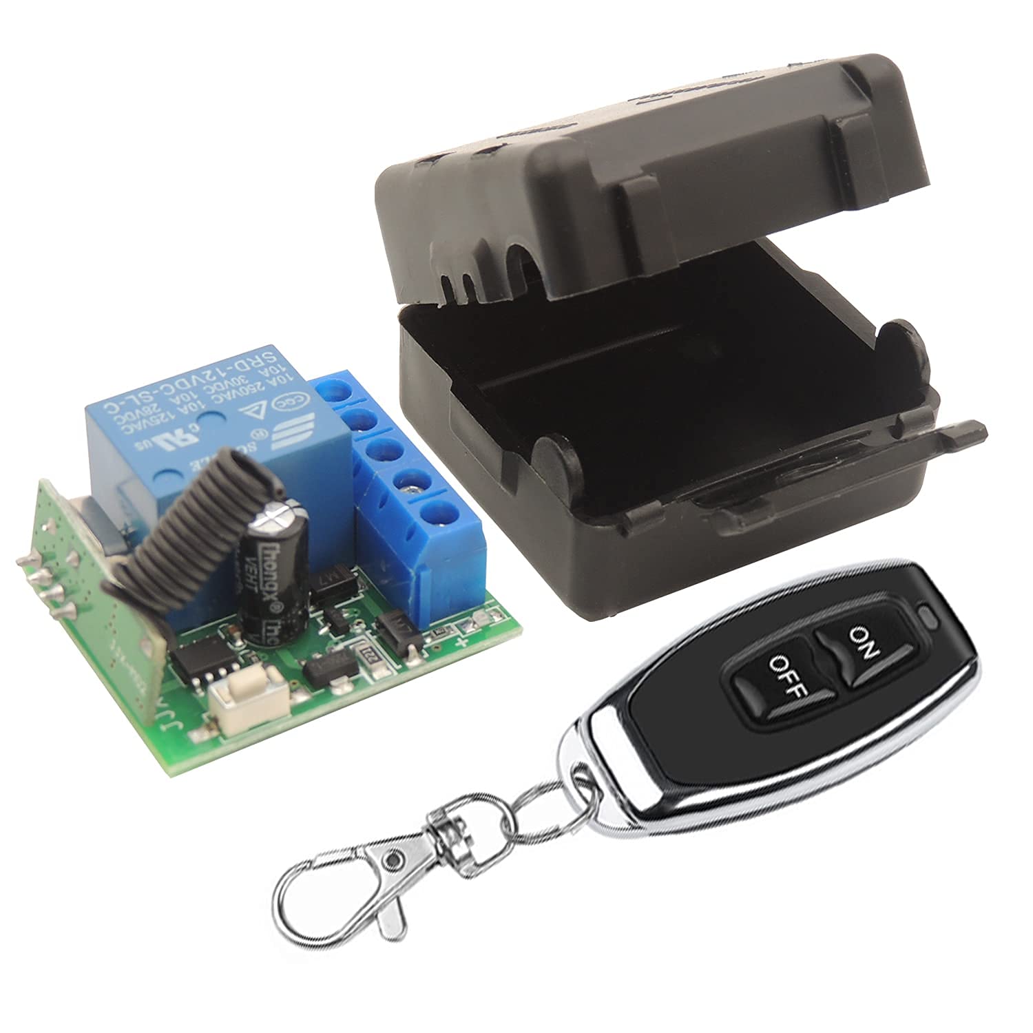
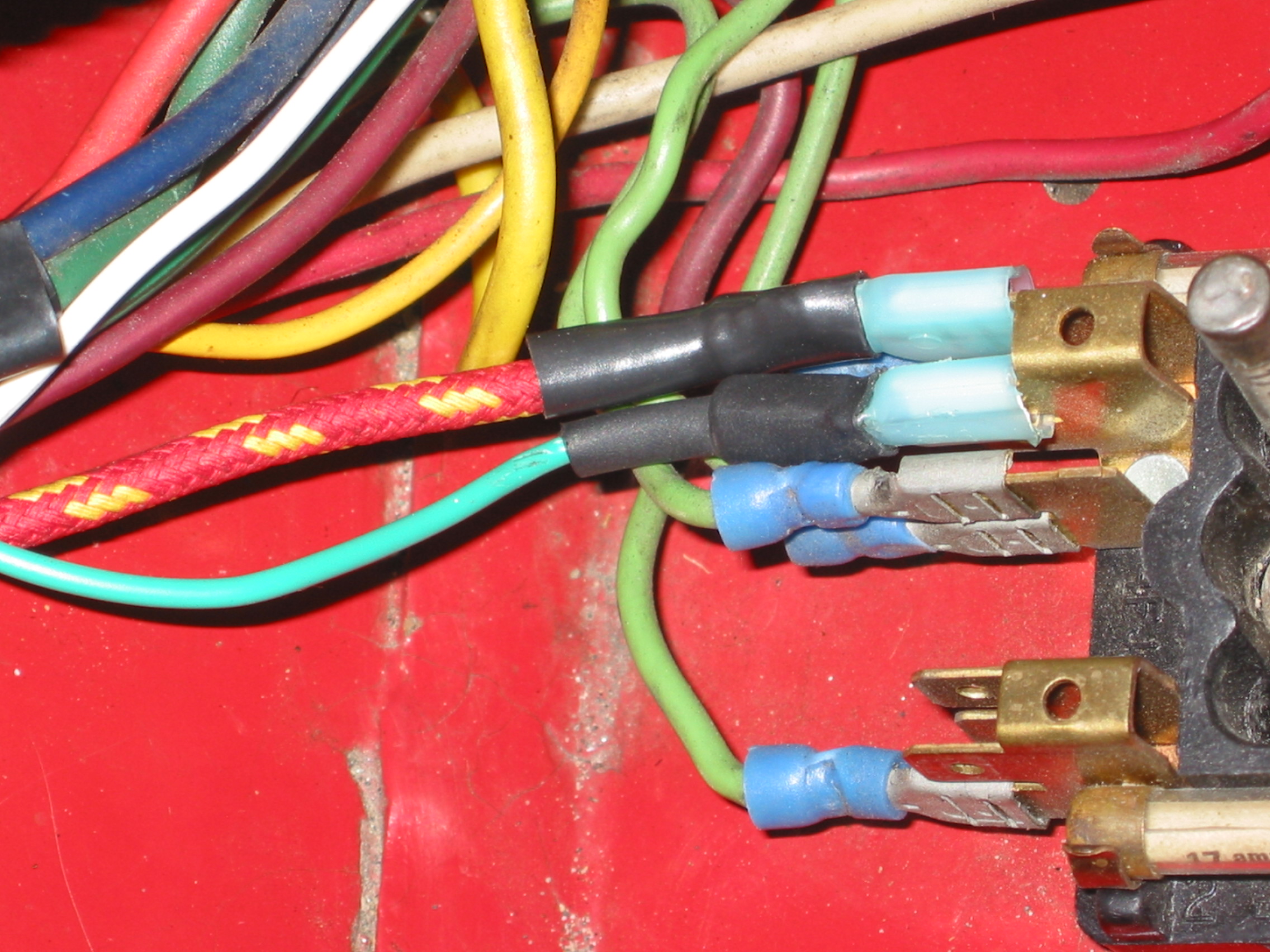
A purple wire provides power to the LED lights and each is grounded with a black wire next to the light assembly. Operation of the lights is through a remote key fob switch in which case the lights turn on for forty seconds, or via a toggle switch under the dash to leave on until toggled off.
RH Front Courtesy Light

LH Front Courtesy Light
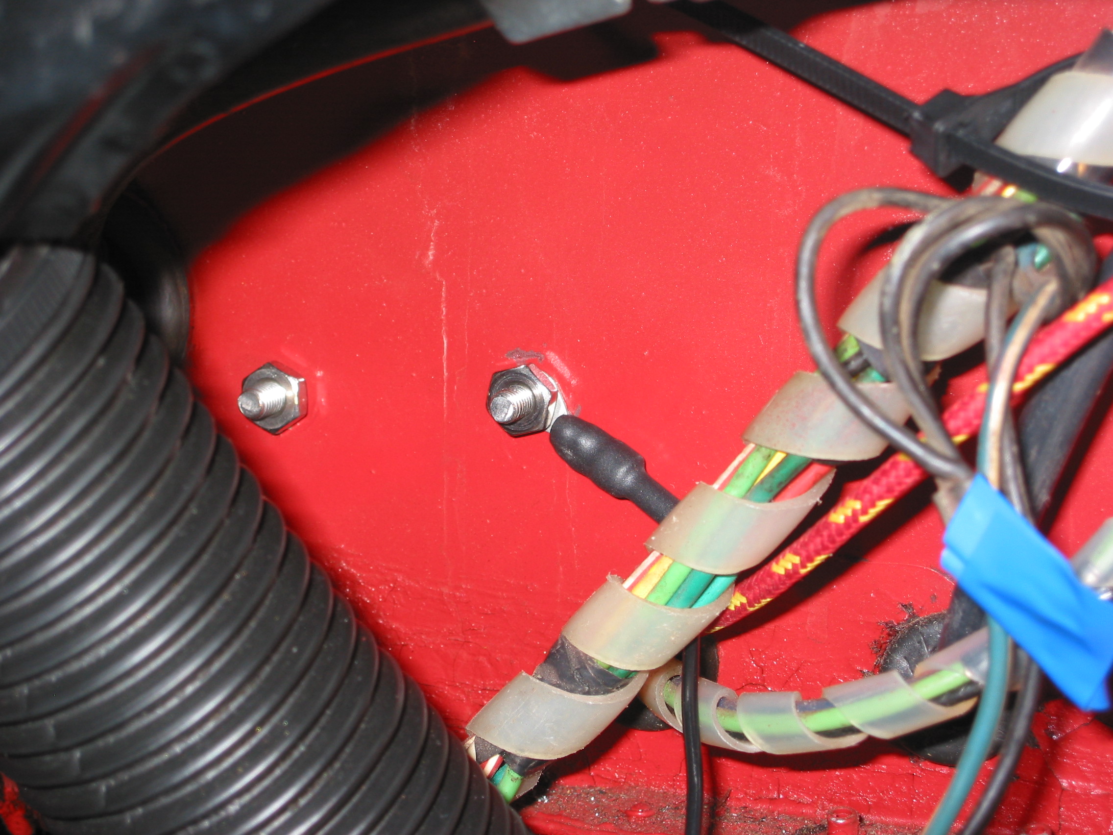
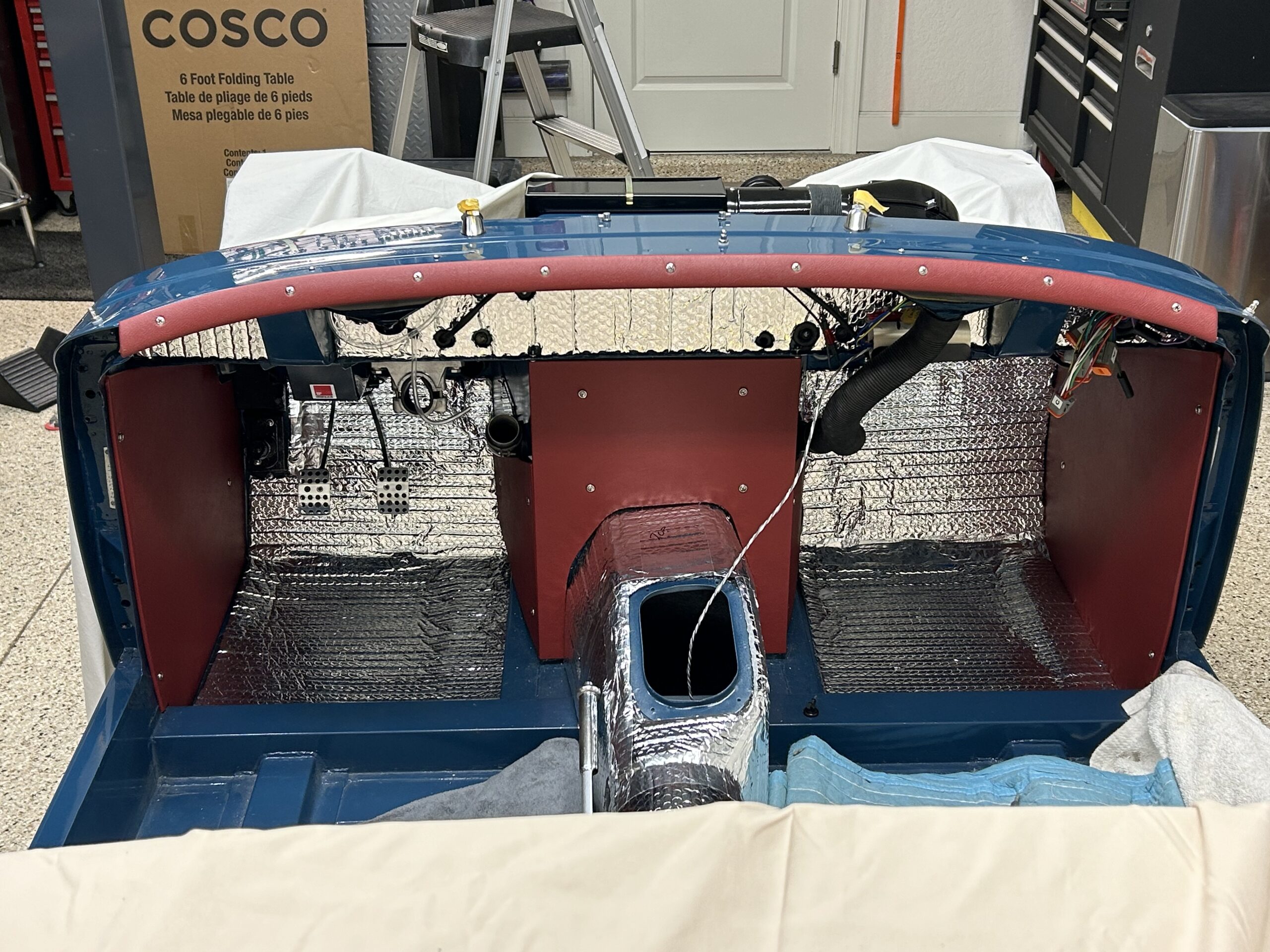
Before installing the dash we wanted to complete the installation of the front courtesy lights as they are not easy to access without the dash, much less with dash in place. We also completed the wiring and testing for the pedal brake switch that can also be seen in the photo below.
LH front courtesy light
We then covered the front aluminum cockpit molding with our red vinyl and installed it on the body. It looks quite handsome.
front cockpit molding vinyl covered
Just to add a touch of bling to our work the chrome rear view mirror went on next. Two chrome oval head #10-32 x 5/8″ machine screws secure the mirror to the captured nuts in the body.
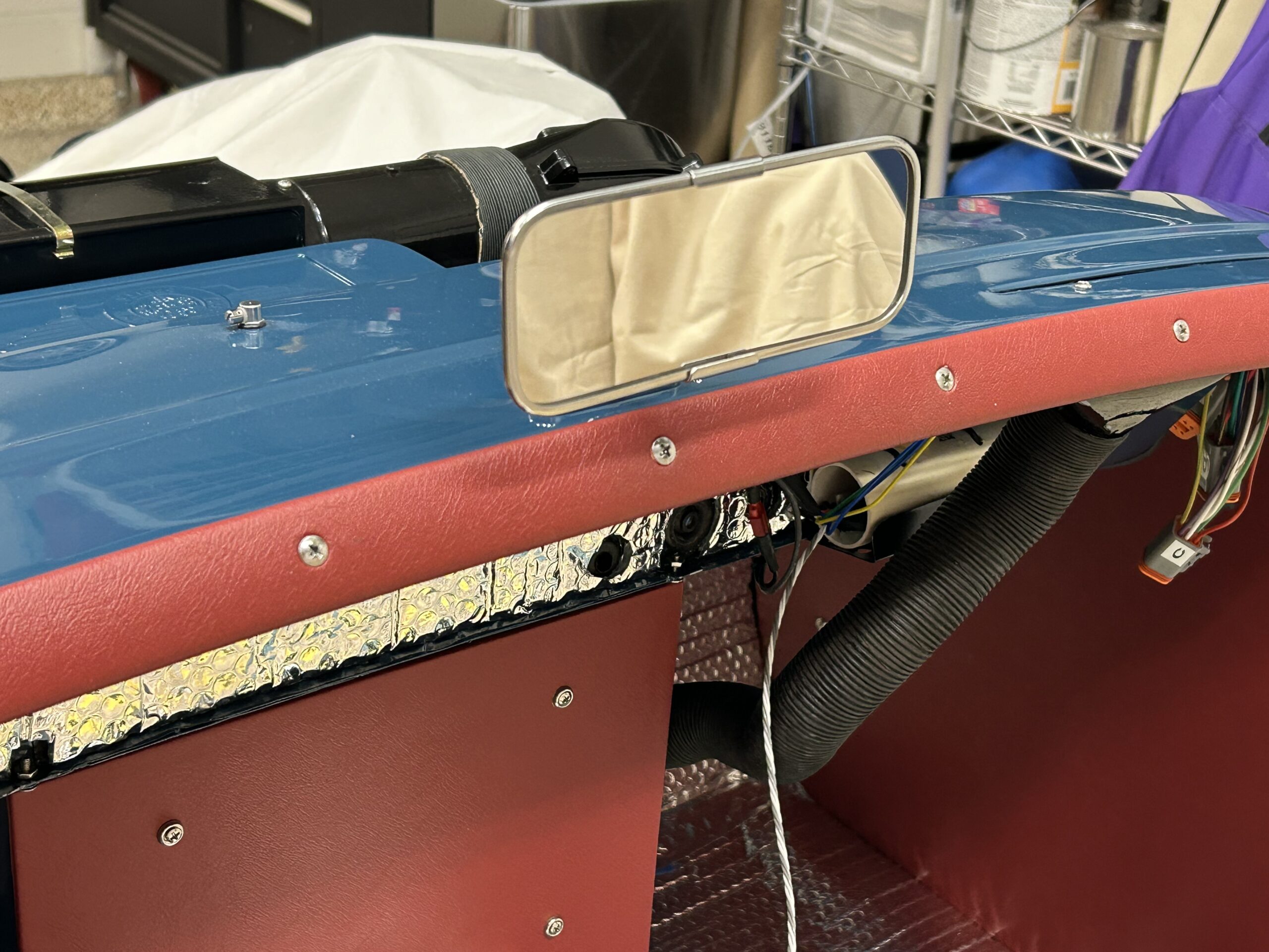
Rear View Mirror
We then added the rear cockpit molding:
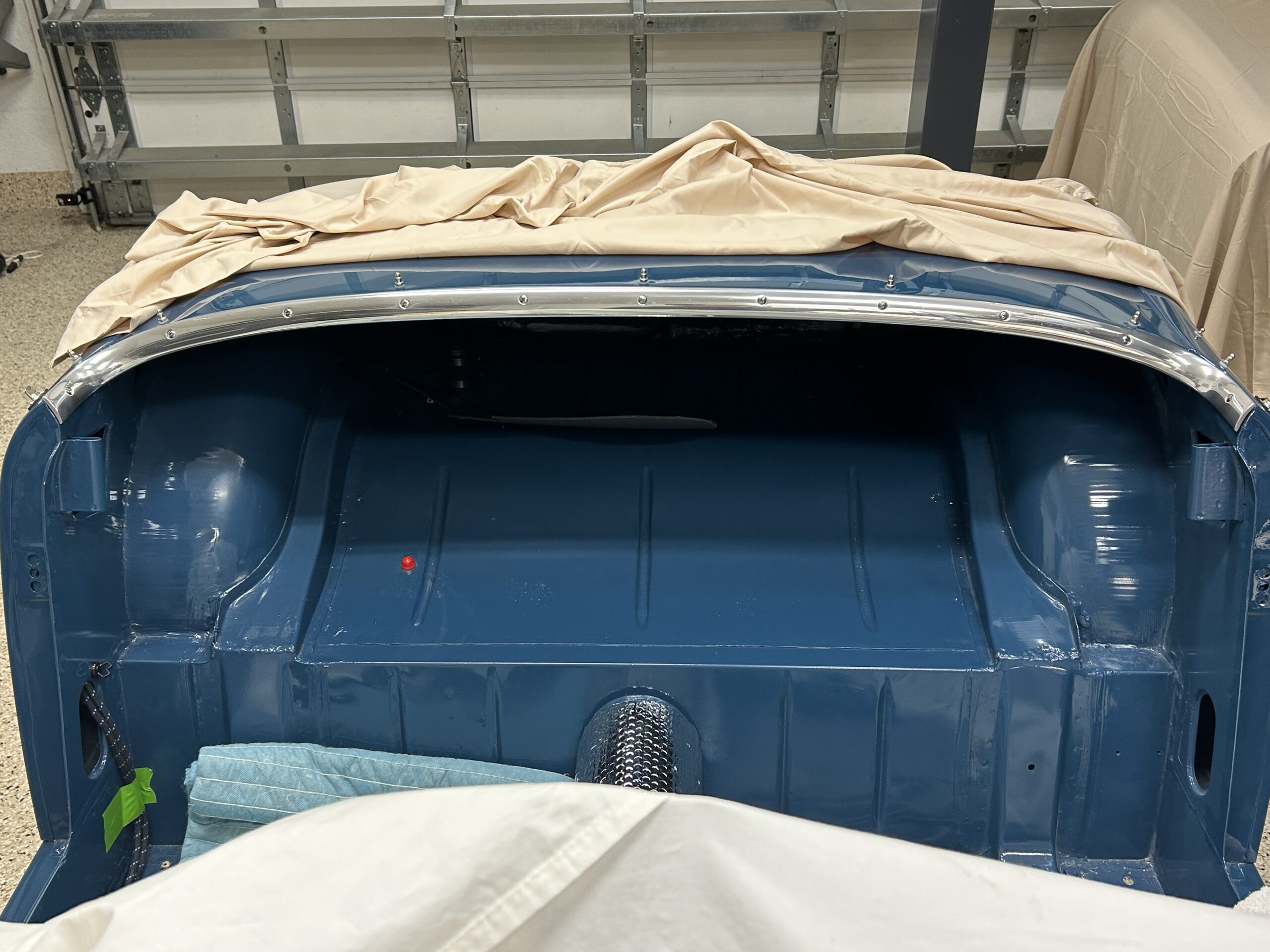
Rear cockpit molding
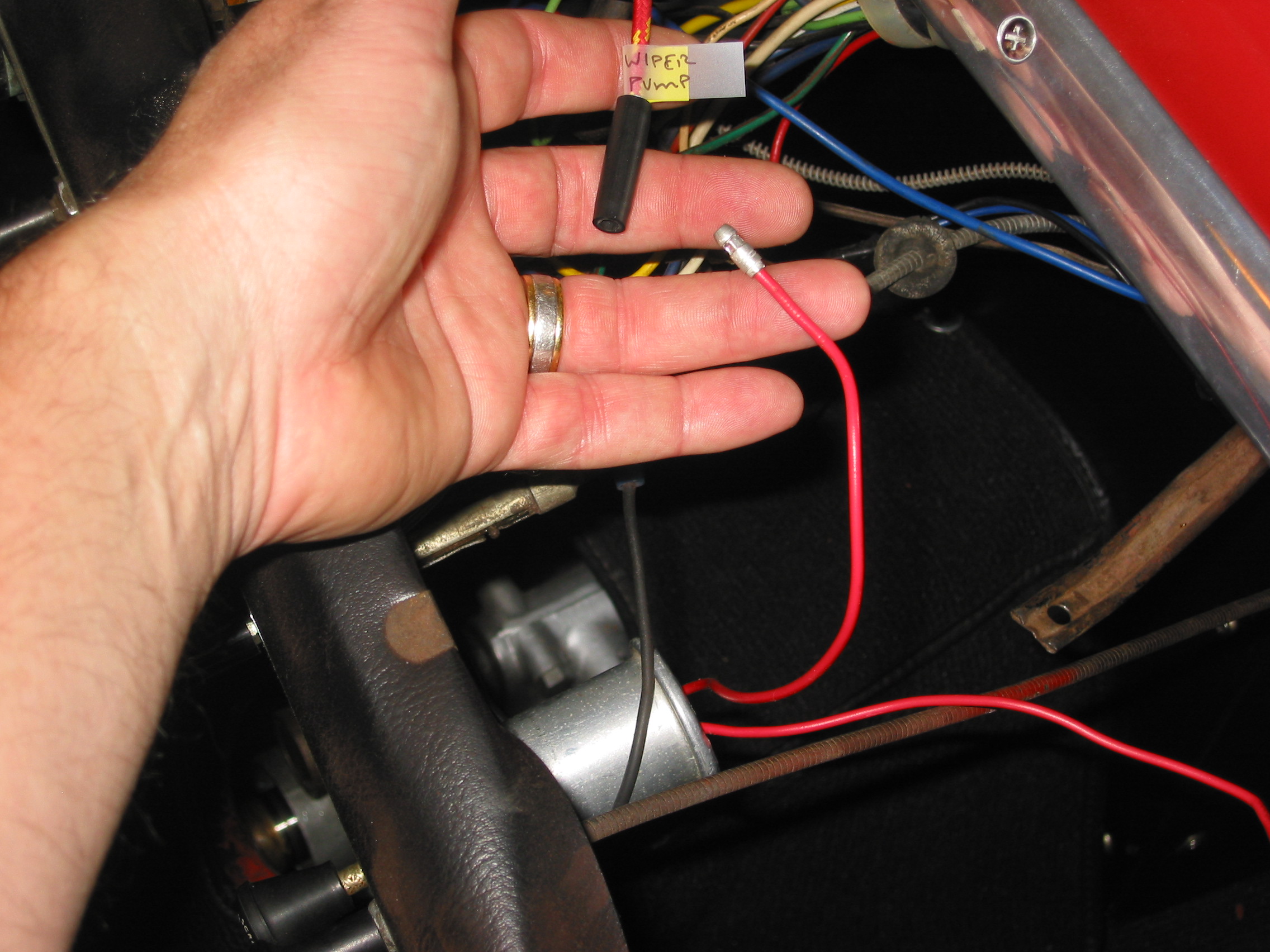
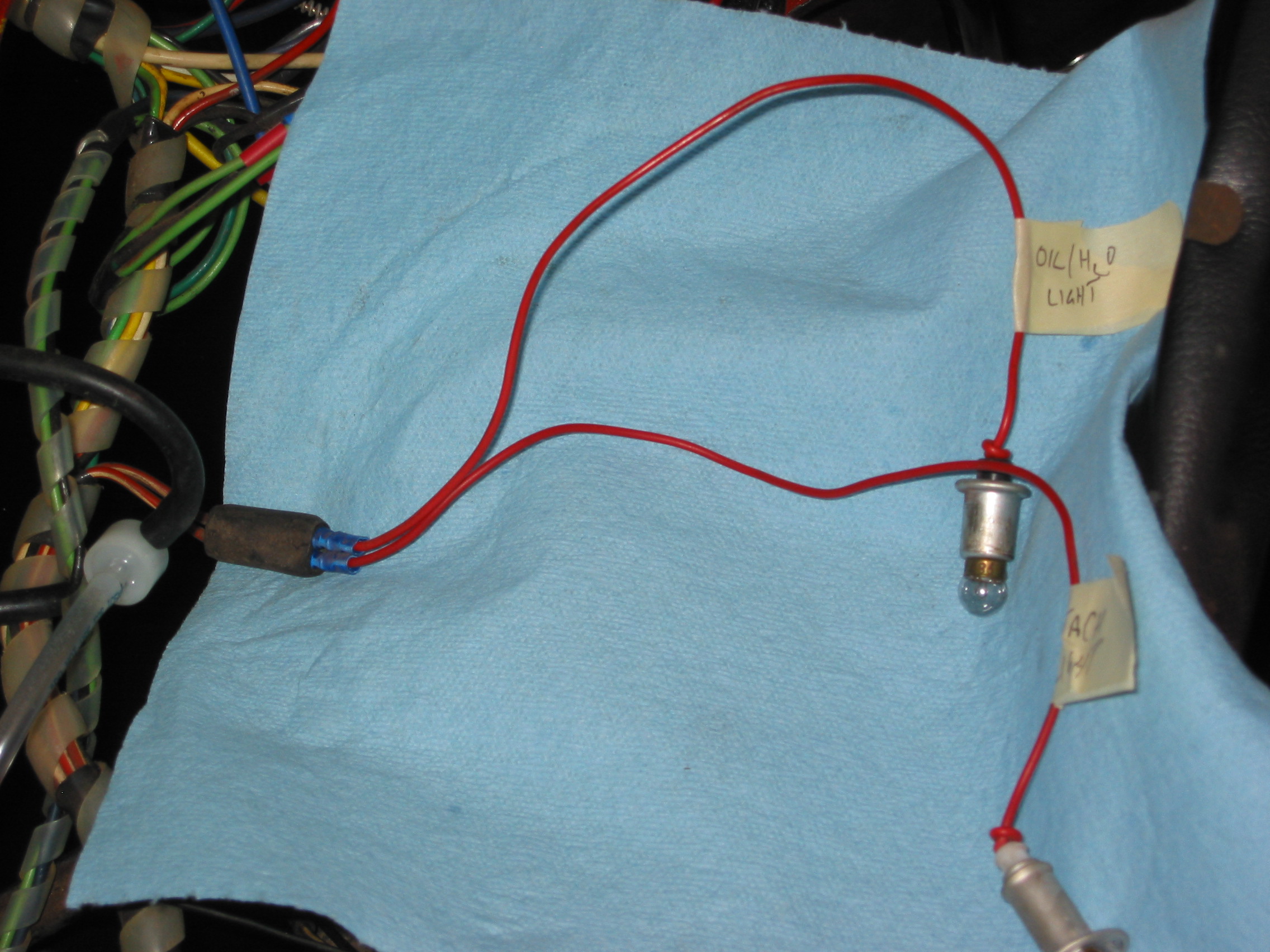
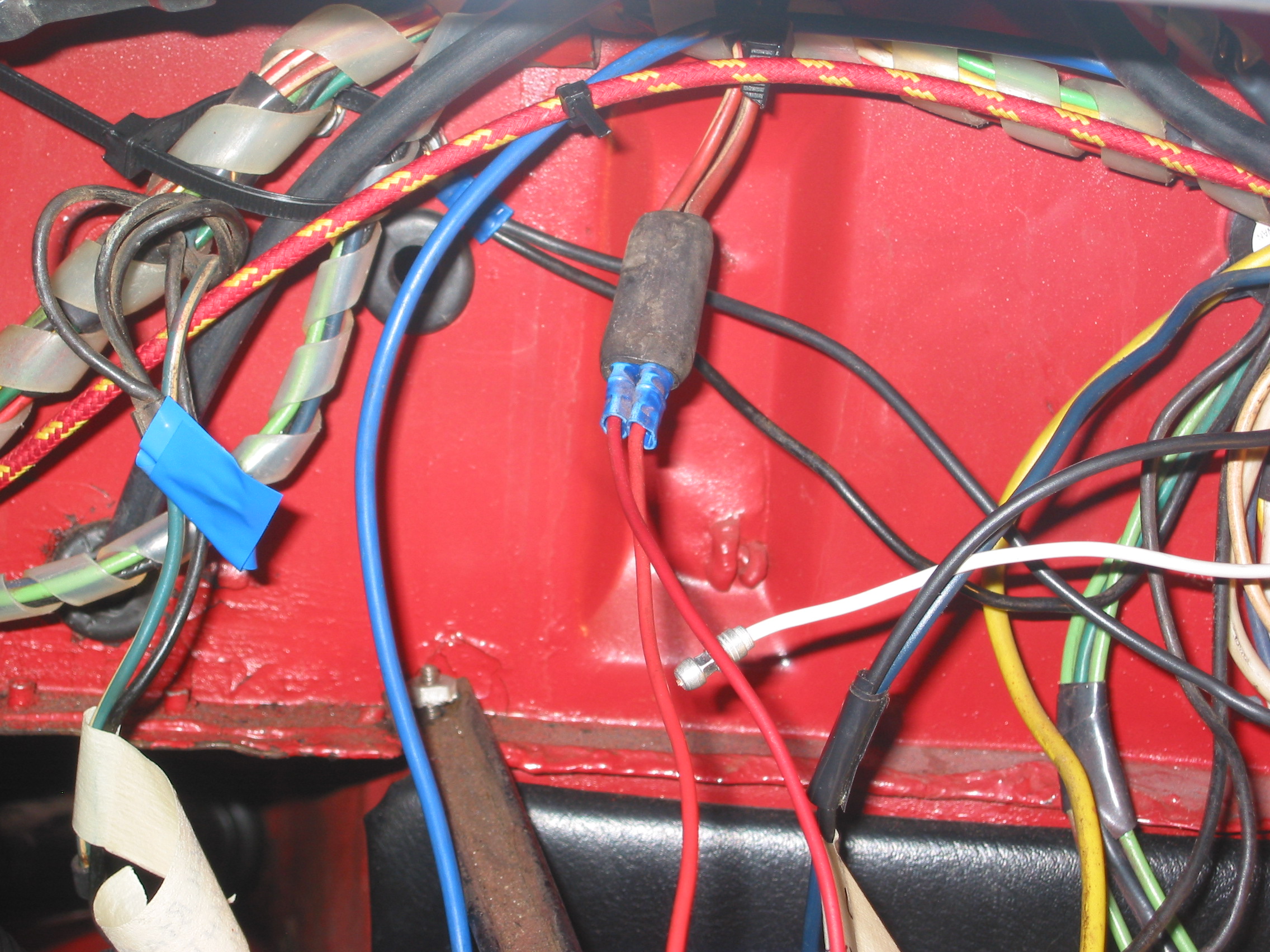
We then installed the LH demister hose to the elbow and nozzle vent. We will be using an AFR gauge to assist with tuning but do not plan to leave it in the car permanently so we ran a red wire from fuse position #19 in our fuse box, through the firewall an into the interior. This wire can be easily removed after we finish tuning.
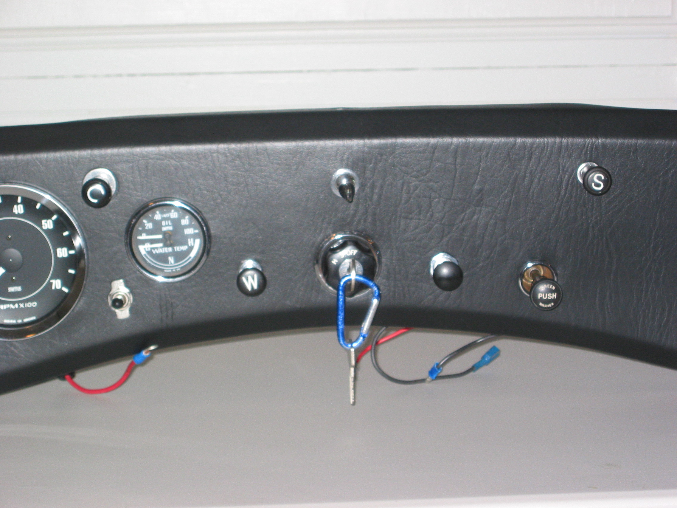
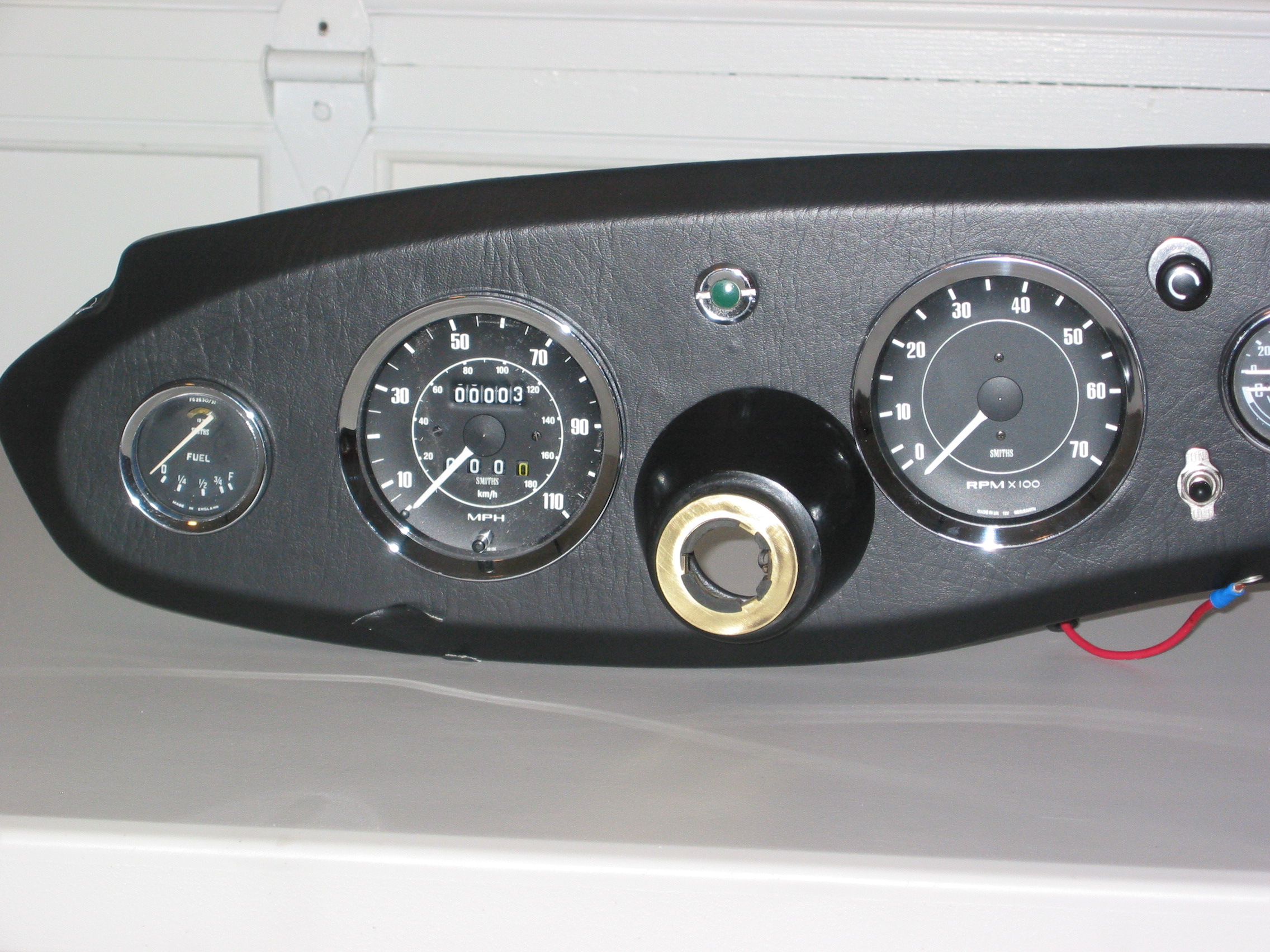
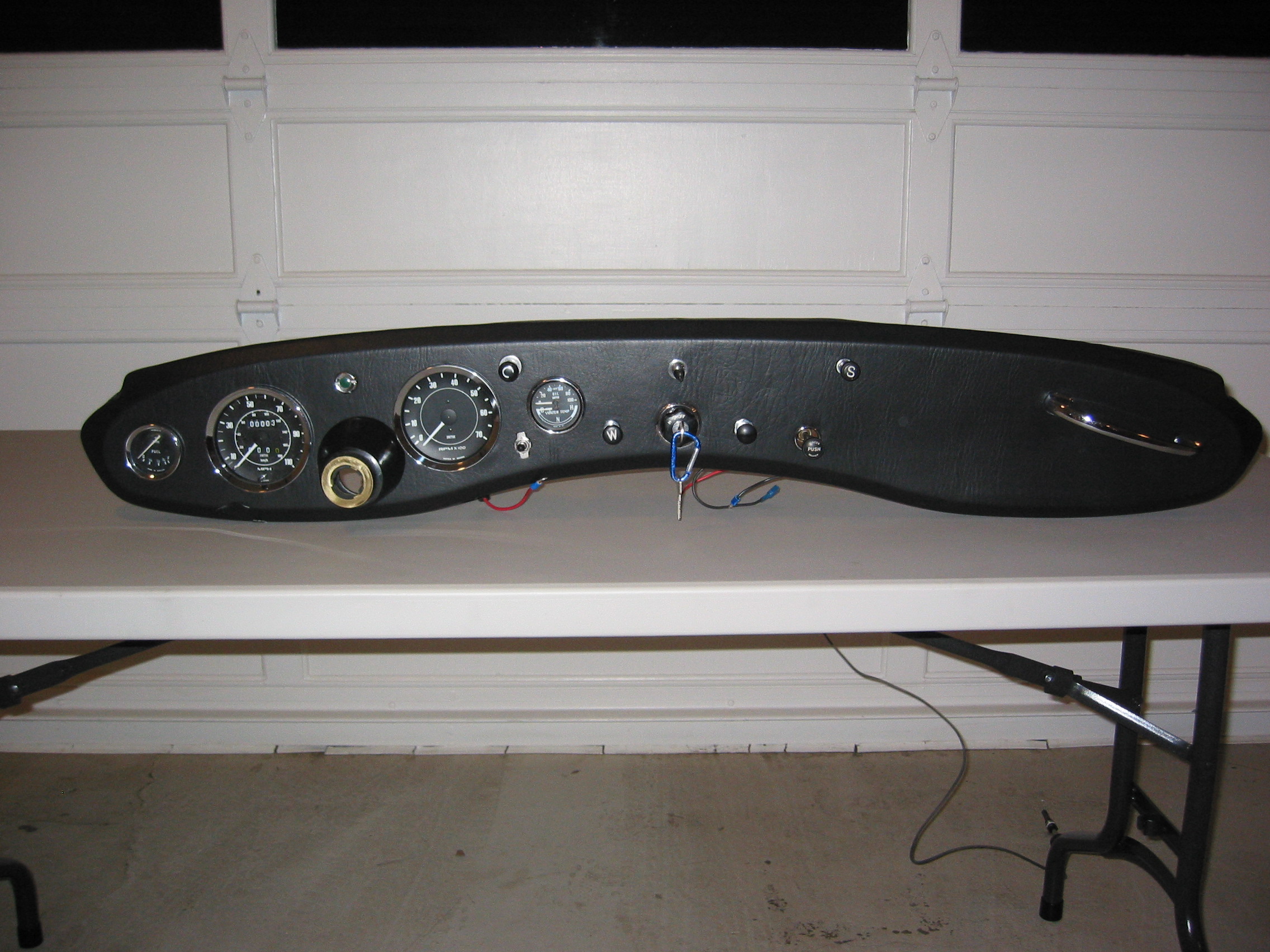
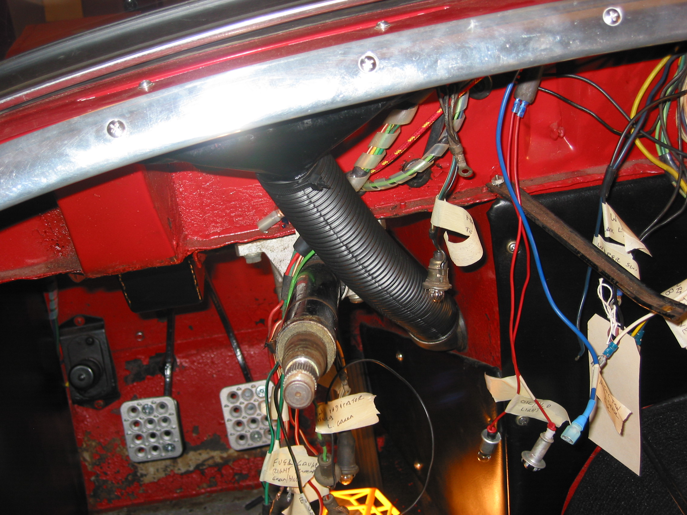
We then began the actual installation of the dash with all of its wiring, gauges, switches and etc. in place. We had seen a tip on the internet to make this task easier. That is to use large zip ties to support the corners of the dash. This allows easy access from above for mating Deutsch connectors, finishing up with a few loose wires and for running cables through the dash and the firewall. As it turned out, it was a great tip and made the job quite a bit easier than it might have otherwise been.
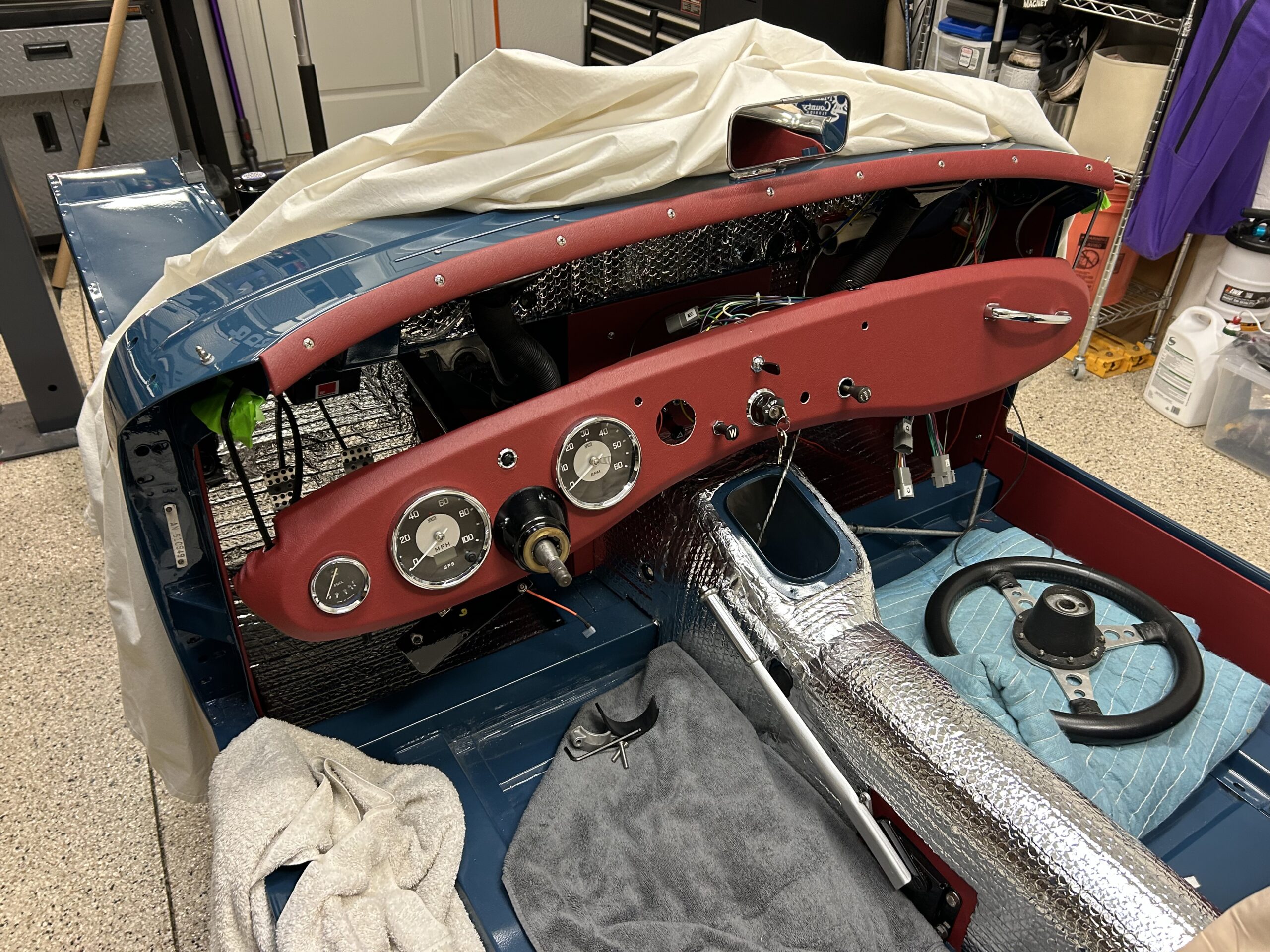
Dash with zip ties to the body
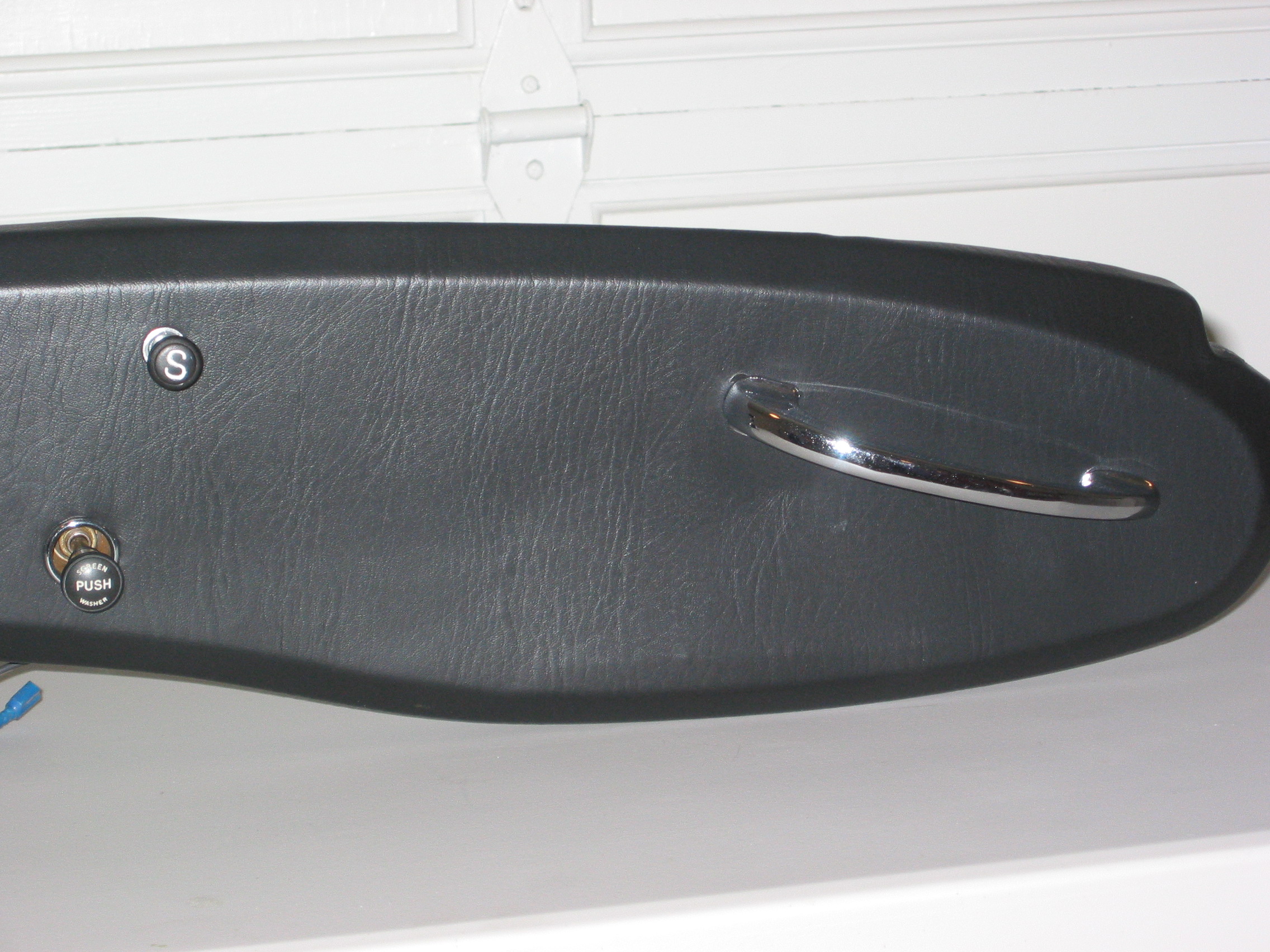
We could then gradually tighten the zip ties and move the dash closer to the body. Ultimately, we cut the zip ties and inserted the 1/4″-28 – 1″ hex head bolts and tightened each corner.
Care must be taken with three items 1. one must keep an eye on the steering shaft so that it remains free in the column bezel. 2. There are two braces under the dash that secure the dash to the firewall. The braces must be above the lip that they mount to on the firewall before the dash to body bolts go in on the corners, otherwise they are difficult to properly position. This is especially true in our case since the braces serve as the platform for our supplementary switch panel behind the dash. 3. Routing the capillary tube for the water temperature gauge and the copper pipe for the oil pressure must be approached cautiously to avoid damage to either.
The installation of the individual items associated with the dash is covered in the attached video. Once we had the dash in place we began testing all of our circuits. Everything seems to functioning properly! A major achievement in the process toward assembling the Bugeye.
Bugeye Restoration Video Episode Eighty-six:
https://vimeo.com/1006256130/a0a01395e3?share=copy
0:00 – Front courtesy lights connected
0:21 – Brake light wiring
1:11 – Covering and installing the aluminum cockpit molding
2:56 – Rear view mirror installed
3:18 – Rear cockpit molding installed
3:50 – LH demister hose installed
4:00 – Temporary AFR gauge wiring installed
4:22- Dash wiring and installation
8:00 – Zip tying the dash to the car
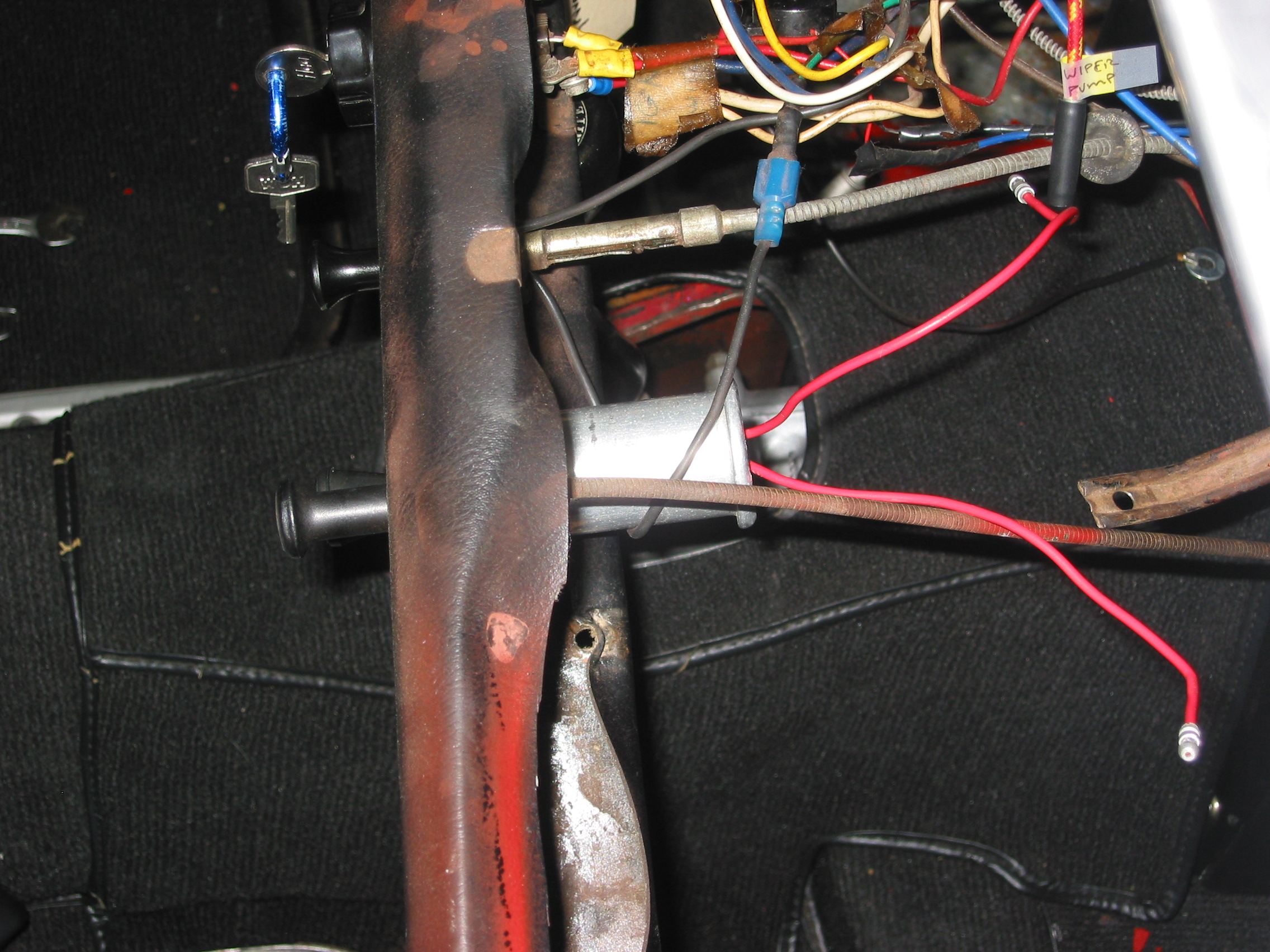
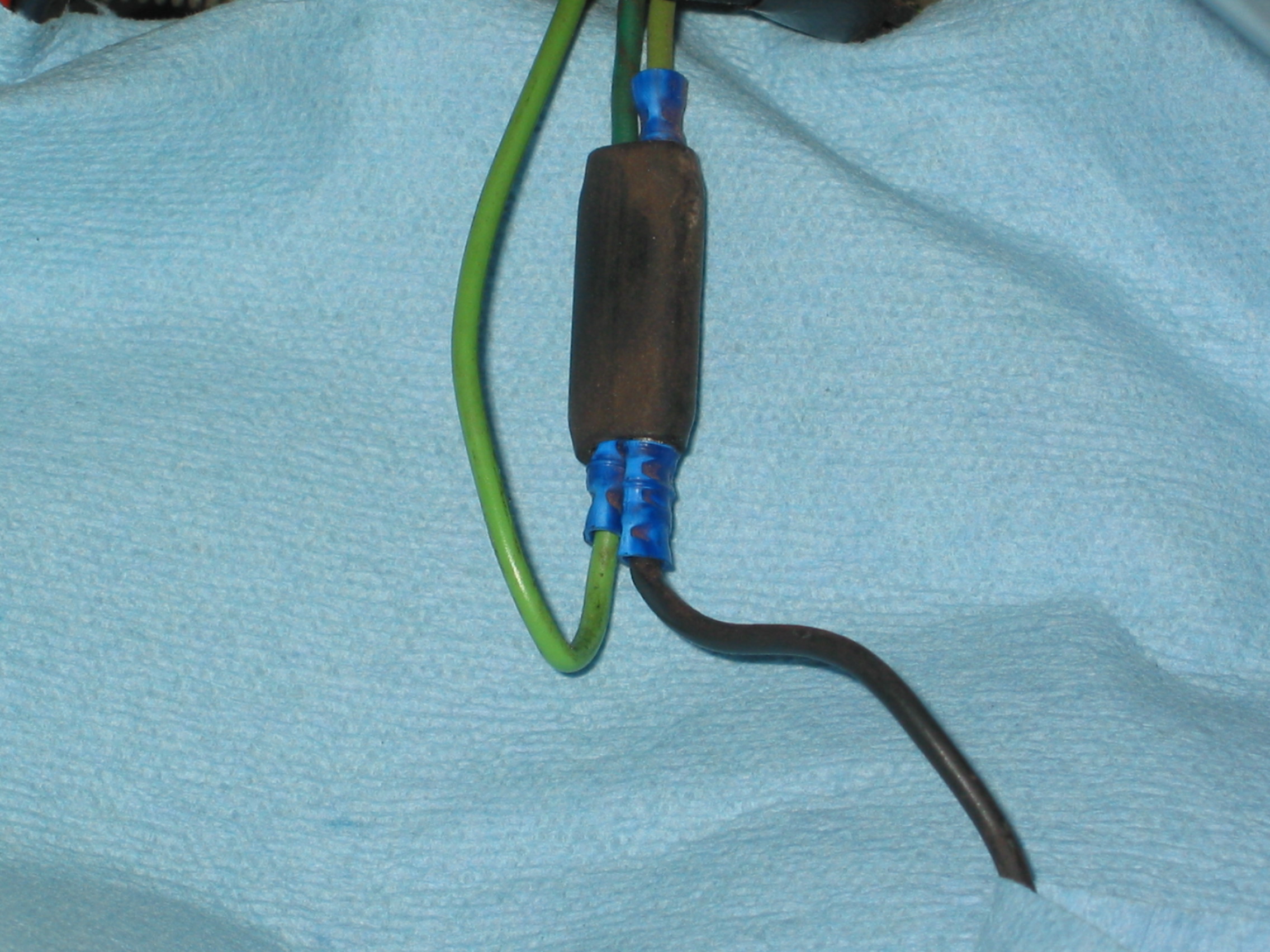
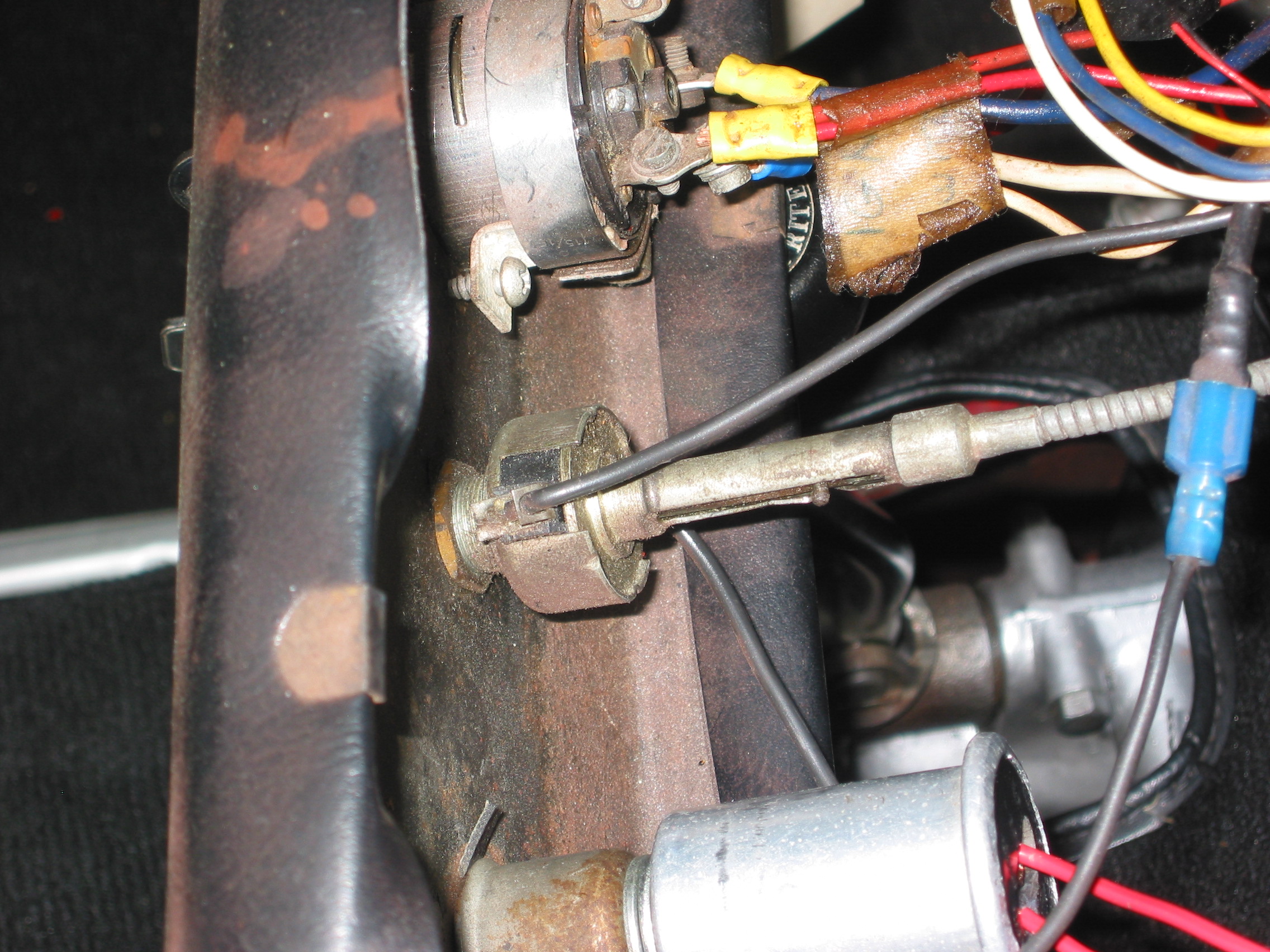
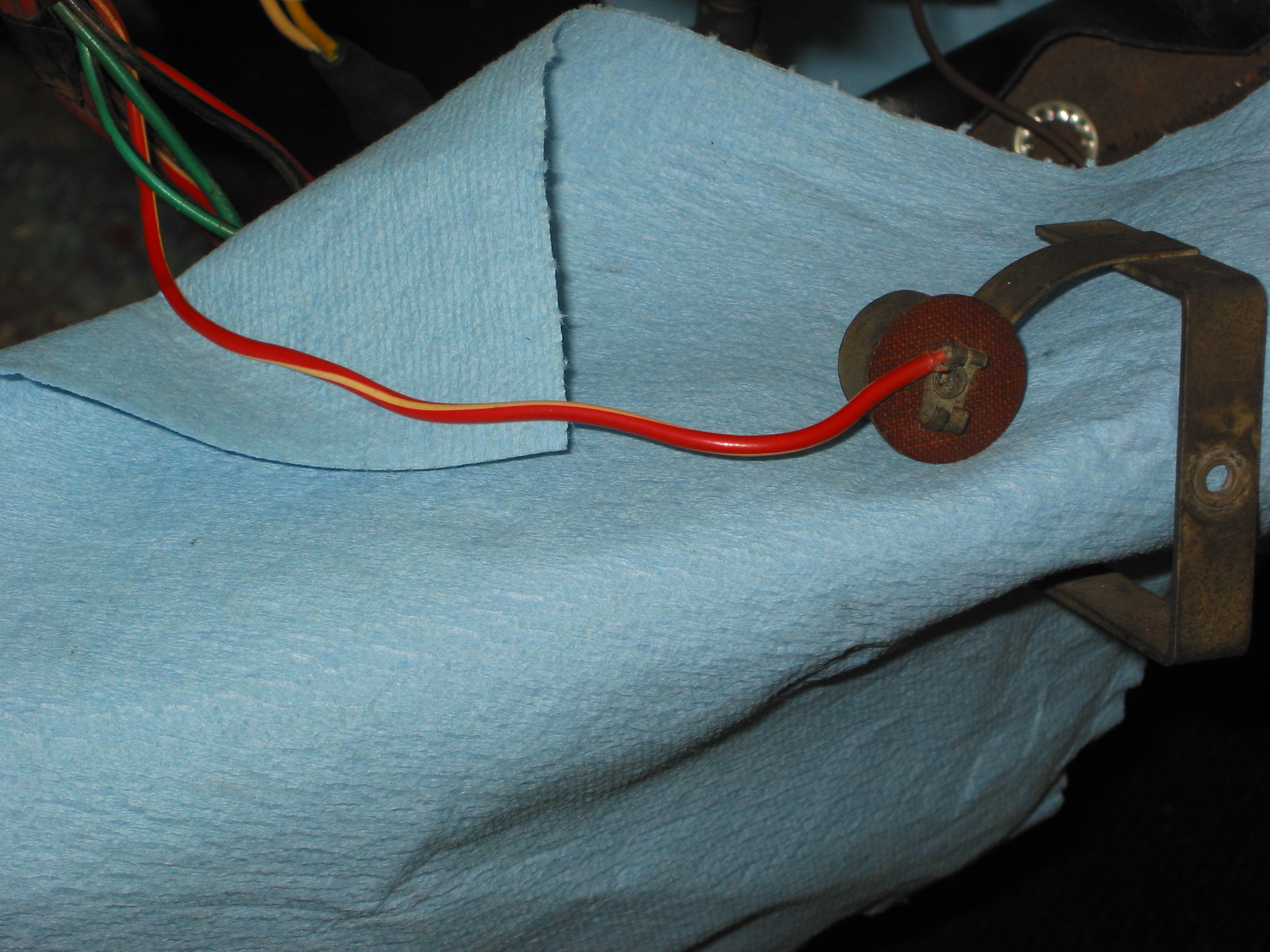
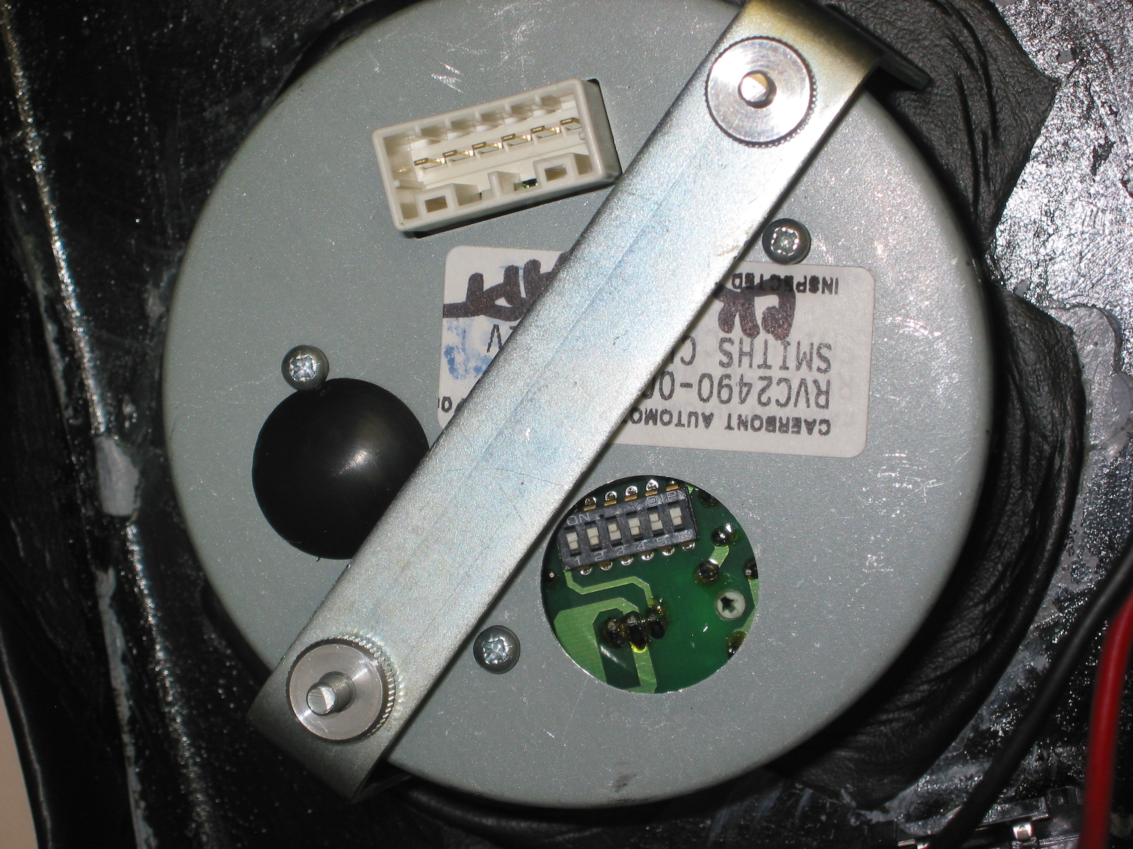
8:47 – Wiper controller rheostat installed
9:07 – Water temperature & oil pressure gauge & pipes installed
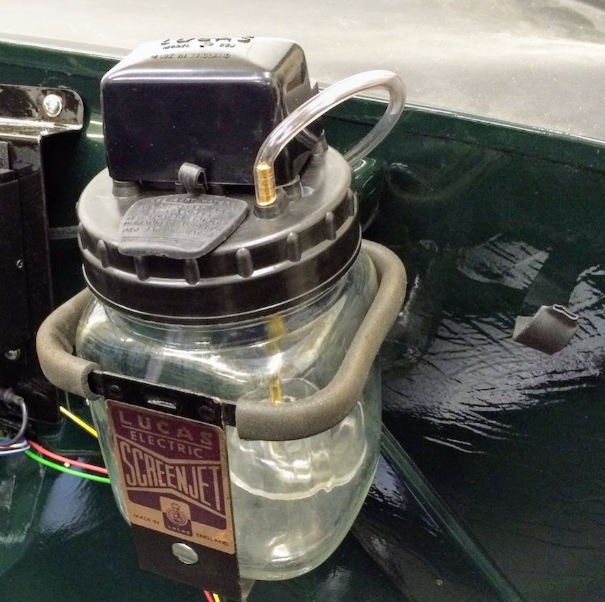
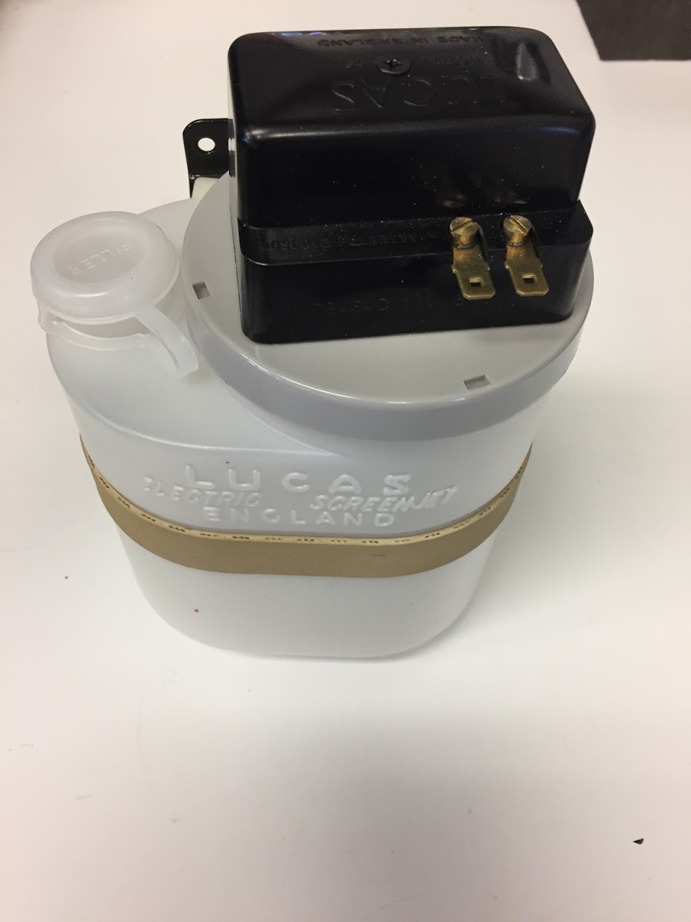
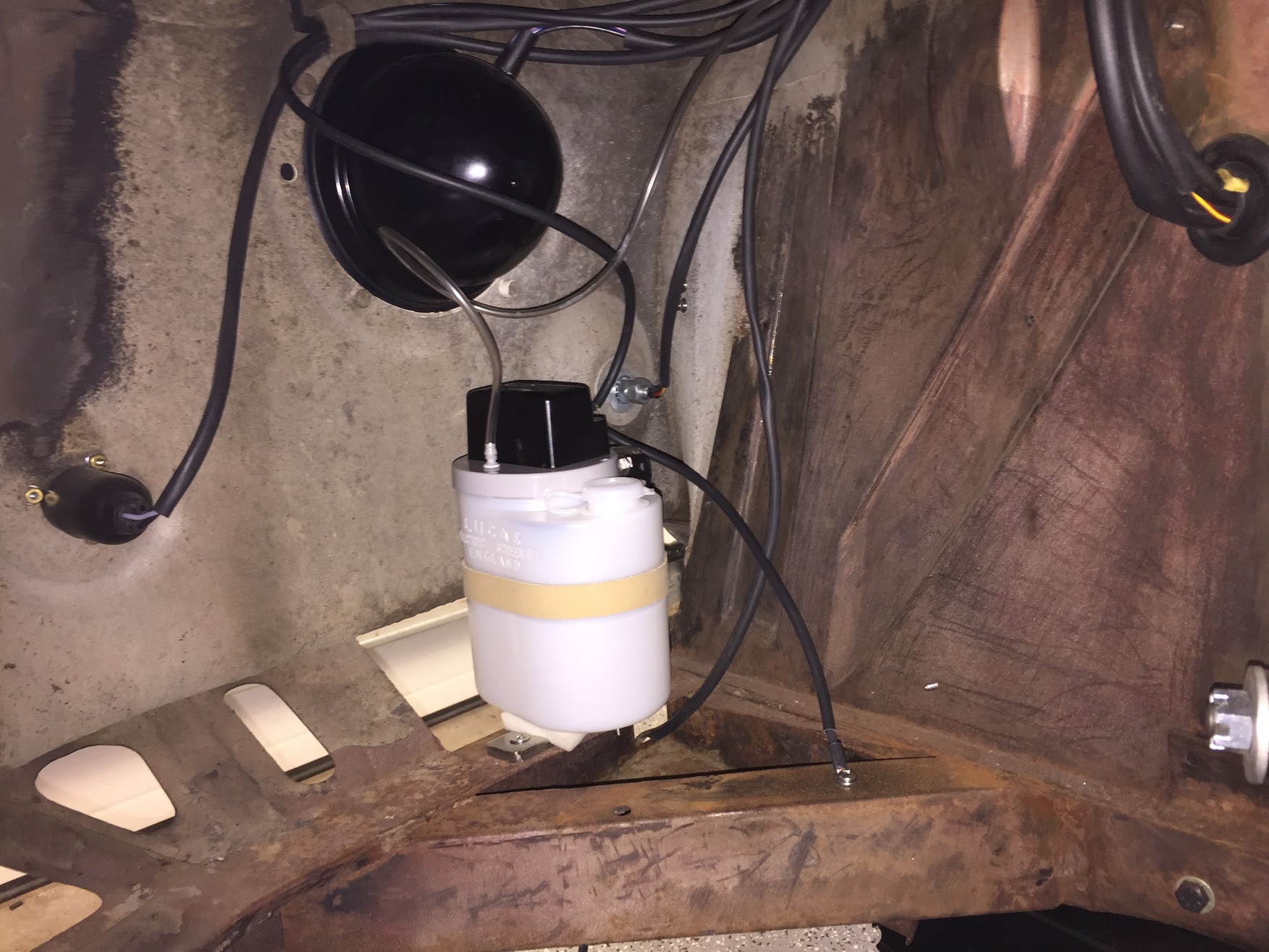
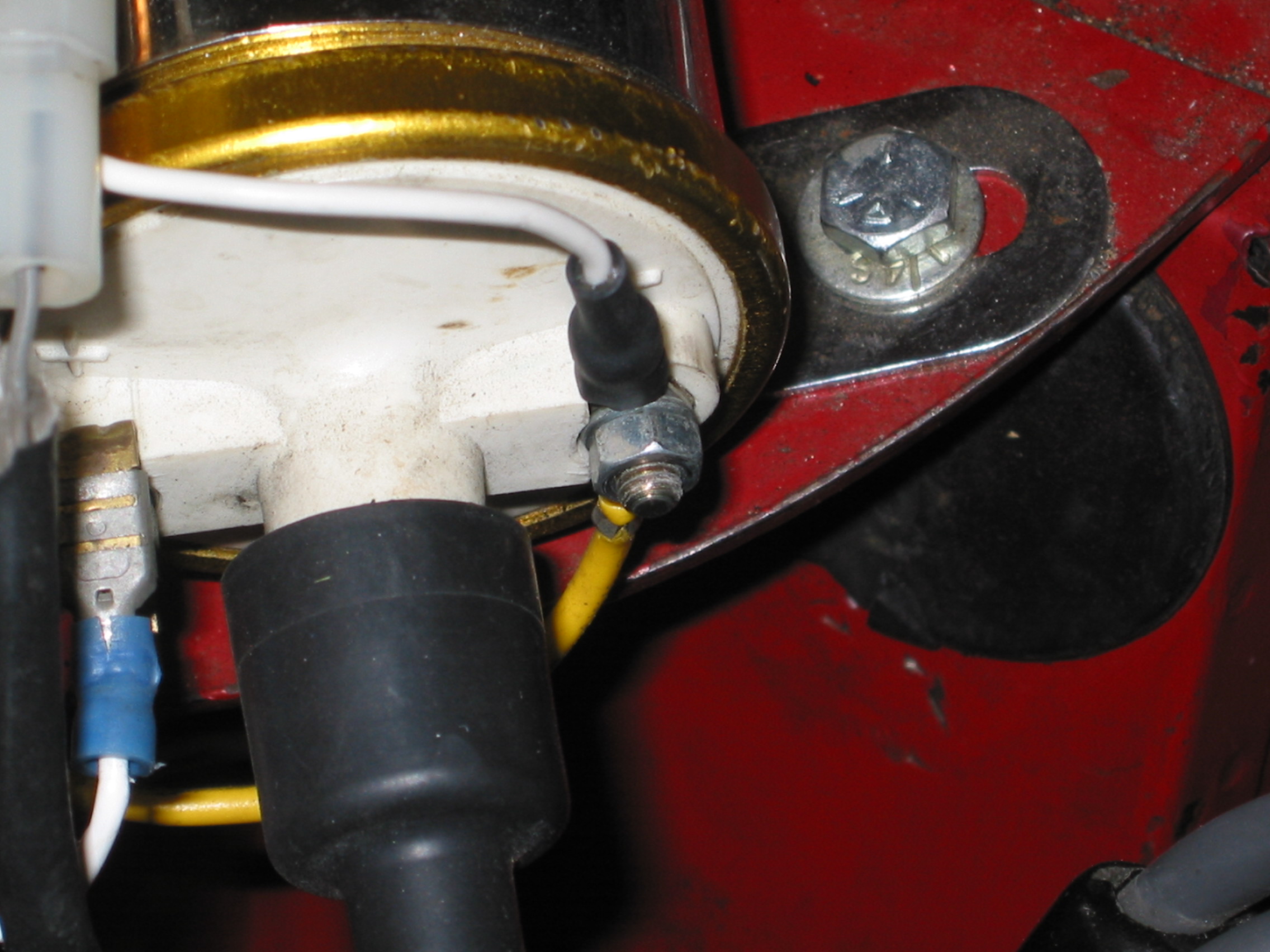
10:00 – Windscreen washer pump hoses and wiring connected
10:19 – Brake wiring connected
10:48 – Started cable installed
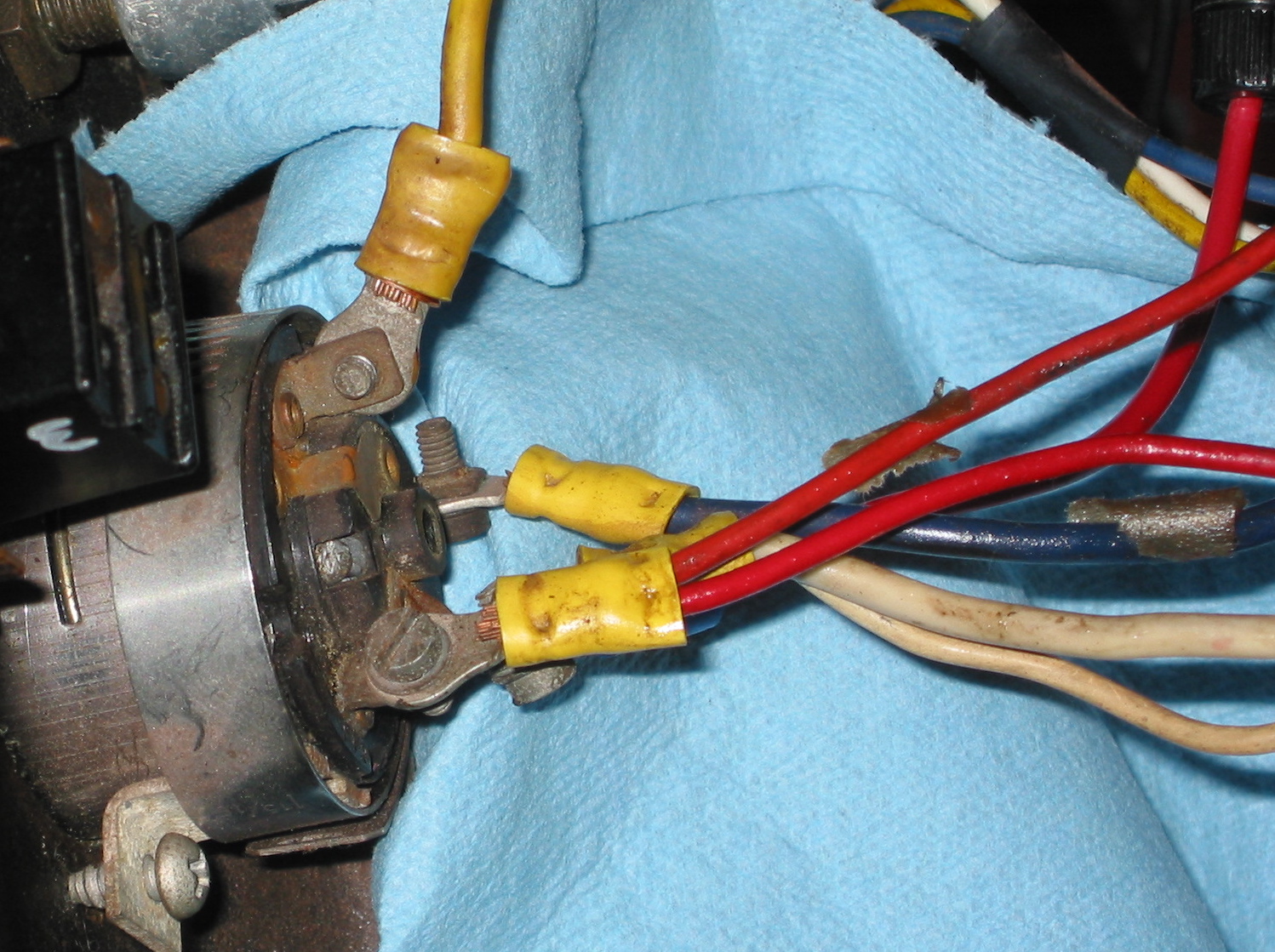
11:05 – Heater switch installed & wires connected
11:12 – Choke cable installed
11:24 – RH ground bus bar wiring
11:39 – Dash to body mounting bolts and braces
12:08 – Electrical circuit testing begins