Gauges, Instruments and Switches
Smiths and Lucas
Lucas was the primary provider of things electric incorporated in the Jaguar MK2 and for that matter most other British cars of the period. Smiths, another British automotive parts manufacturer produced instruments/gauges, heaters, clocks and radios among other components. Eric Kriss, a fellow MK2 restorer, has an excellent history of the relationship of Lucas and Smiths on his Blog: http://fairislepress.com/WP/?p=3736.
The speedometer and tachometer are located immediately behind the steering wheel directly in the driver’s view. Most of the other gauges, instruments and switches are located in the Instrument Panel Assembly in the center of the interior’s dash.
I sent all of my instruments to Nisonger http://www.nisonger.com for cleaning, calibrating and refurbishing where necessary.
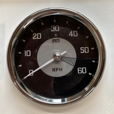
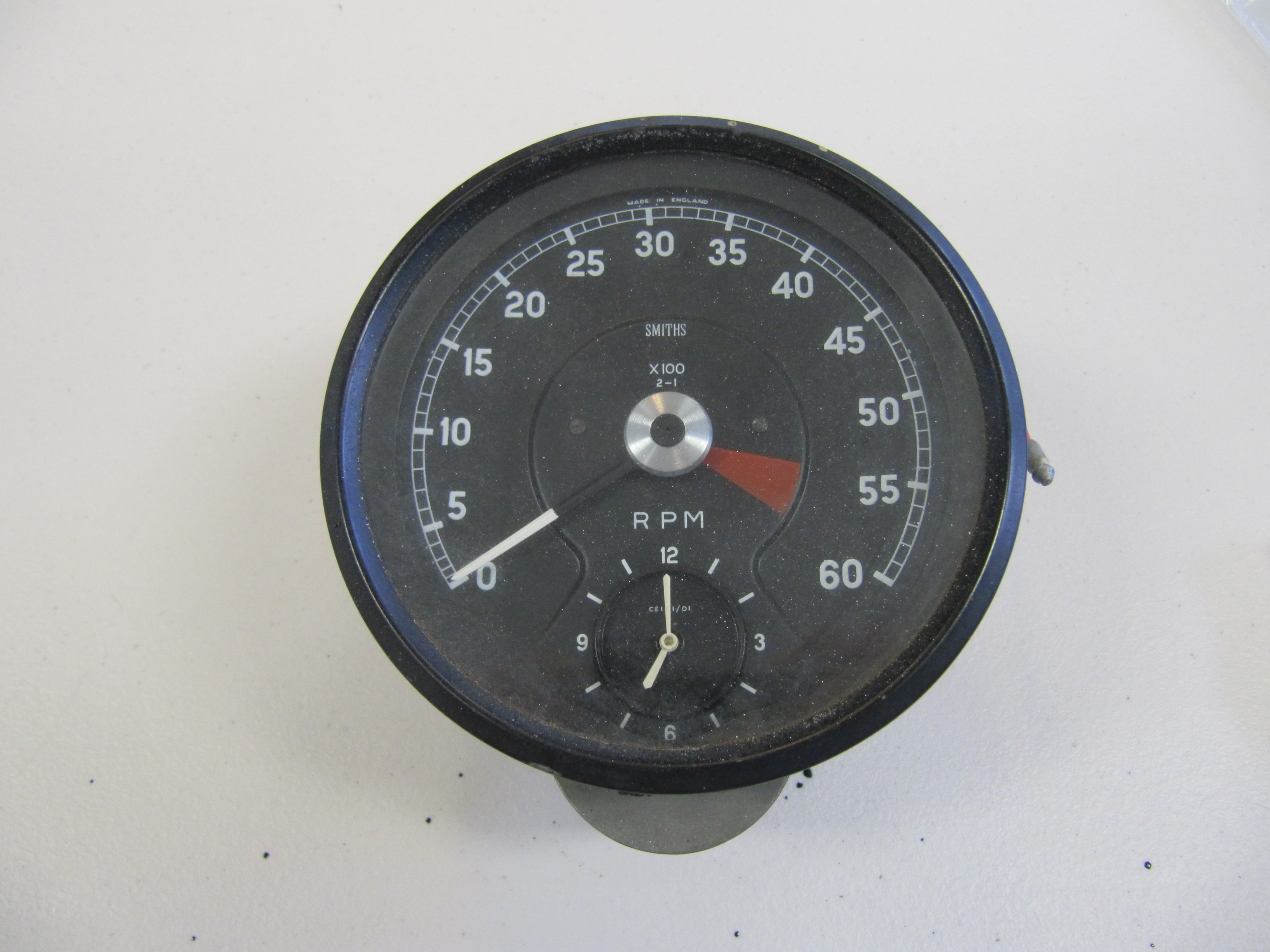
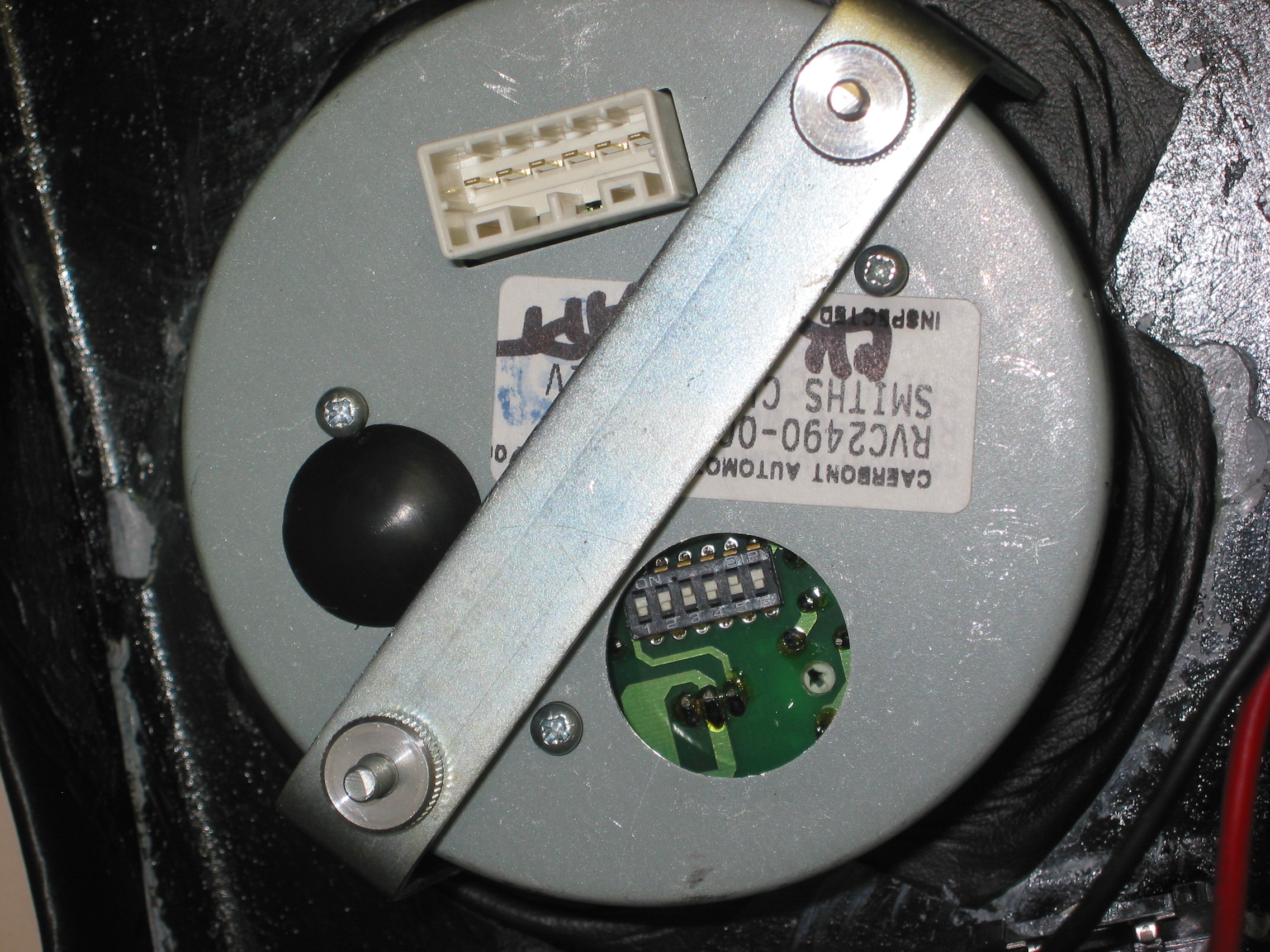
Tachometer
Nisonger converted the tach to a negative ground electronic tachometer. These are the instructions for installation:Nisonger Electronic Tach Instructions
Clock
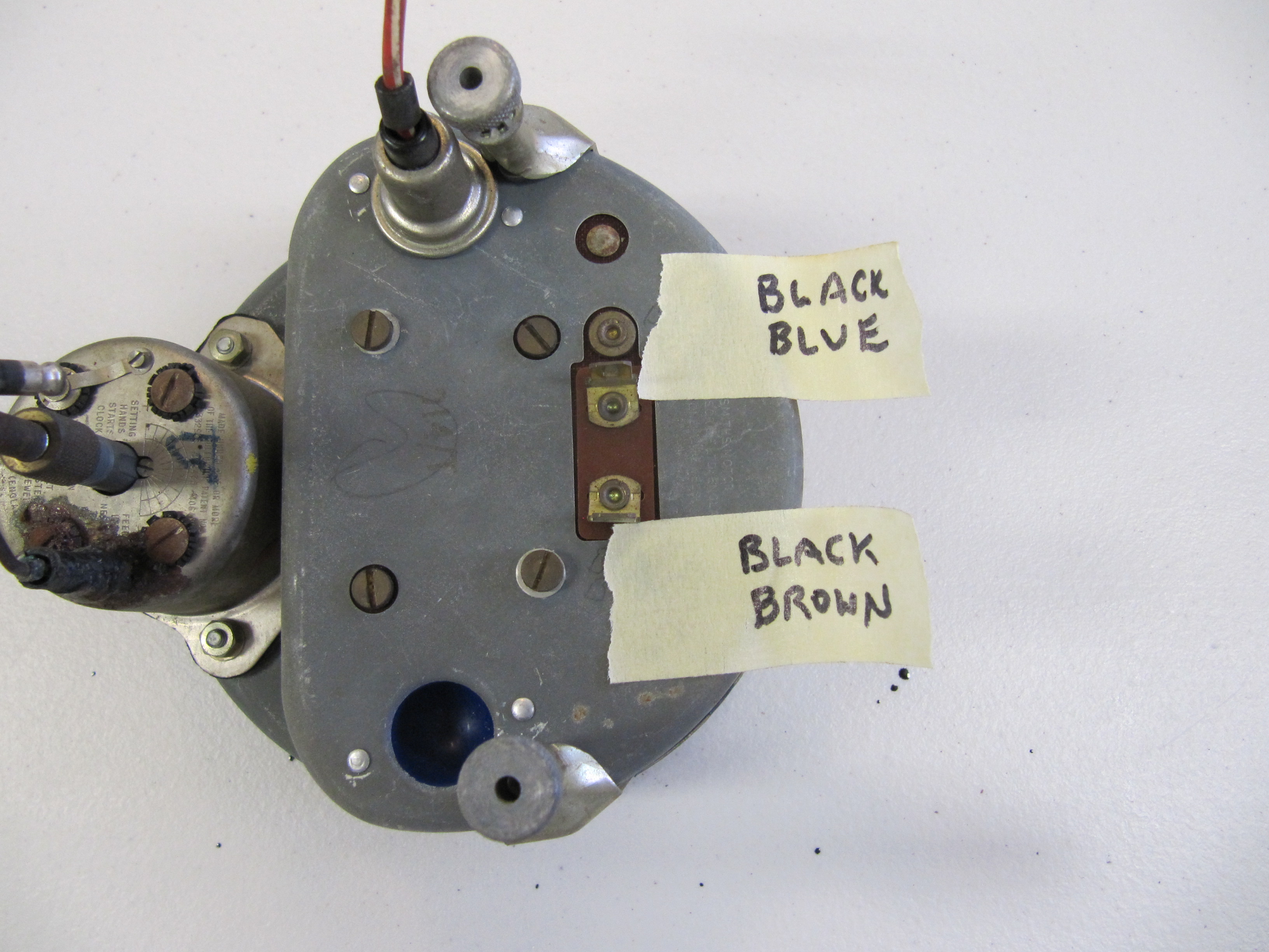
On the MK2, the clock is located inside the tachometer. I removed the clock (loosening two machine screws on the back of the clock/tachometer) and sent it to Mike Eck, mikeeck@optonline.net to have repaired as it was not functioning. He also convert the clock to negative ground.
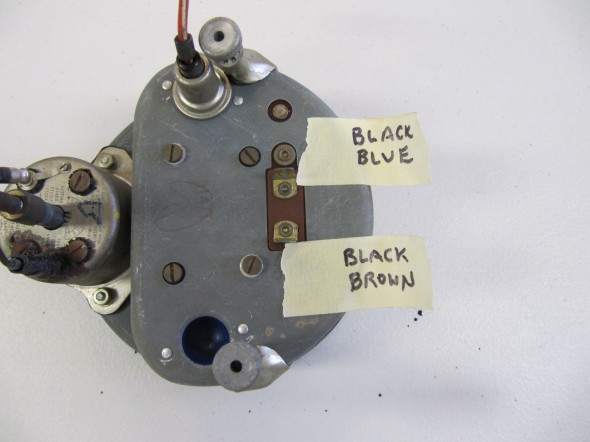
Clock/Tach
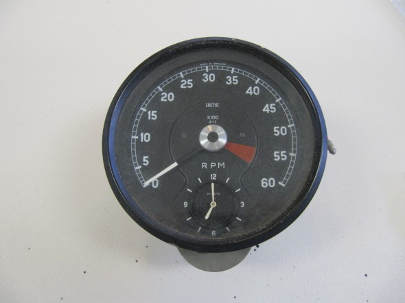
Clock/Tach
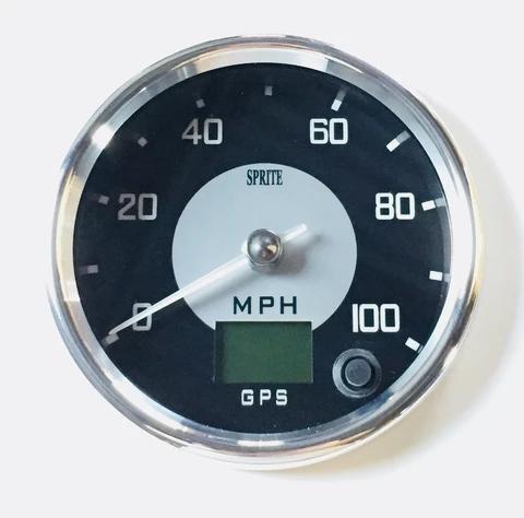
Speedometer/Speedometer Cable
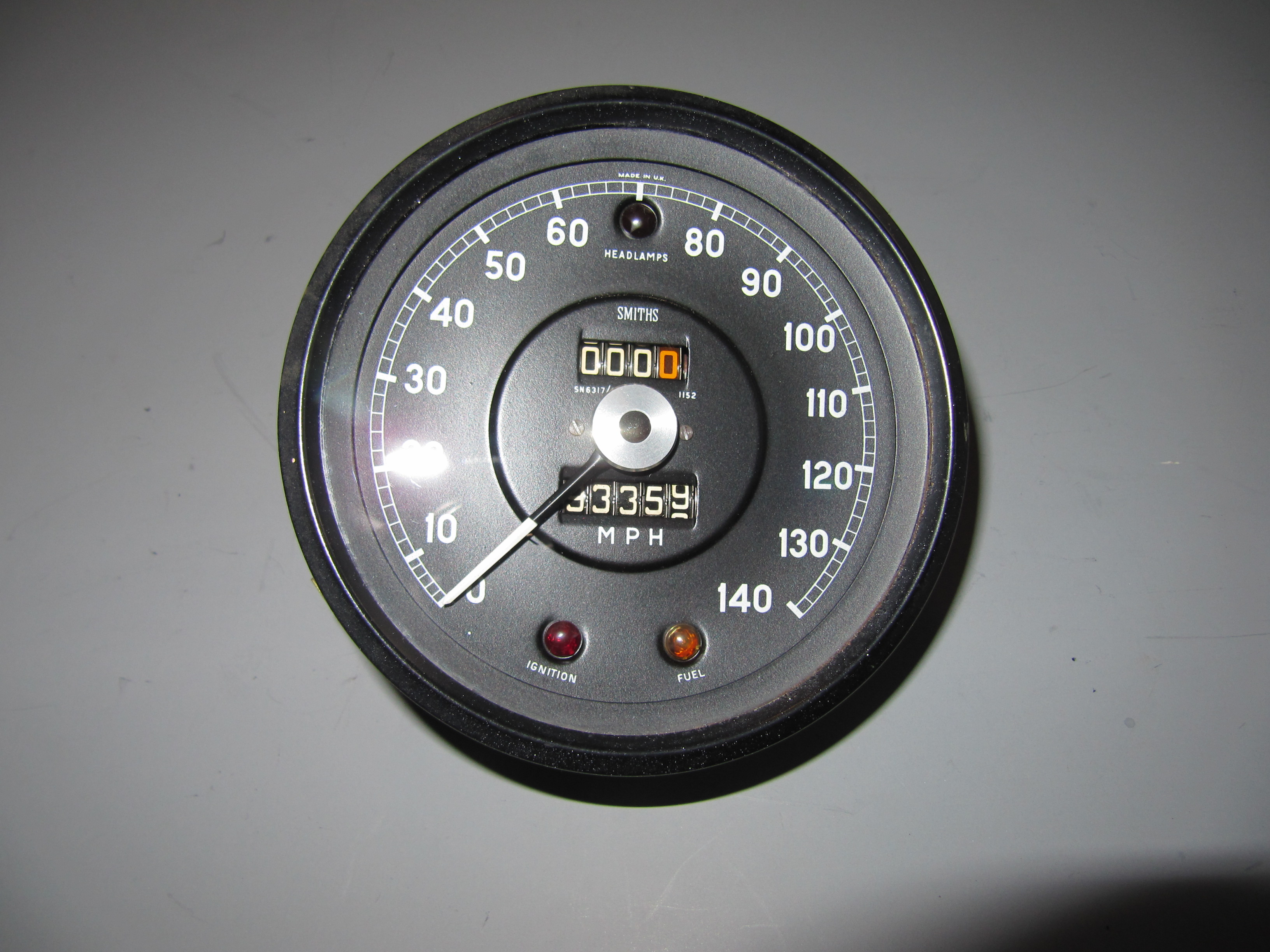
I gently cleaned the speedometer and mailed it to Nisonger with the other gauges. It came back in beautiful condition.
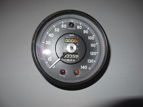
Speedometer
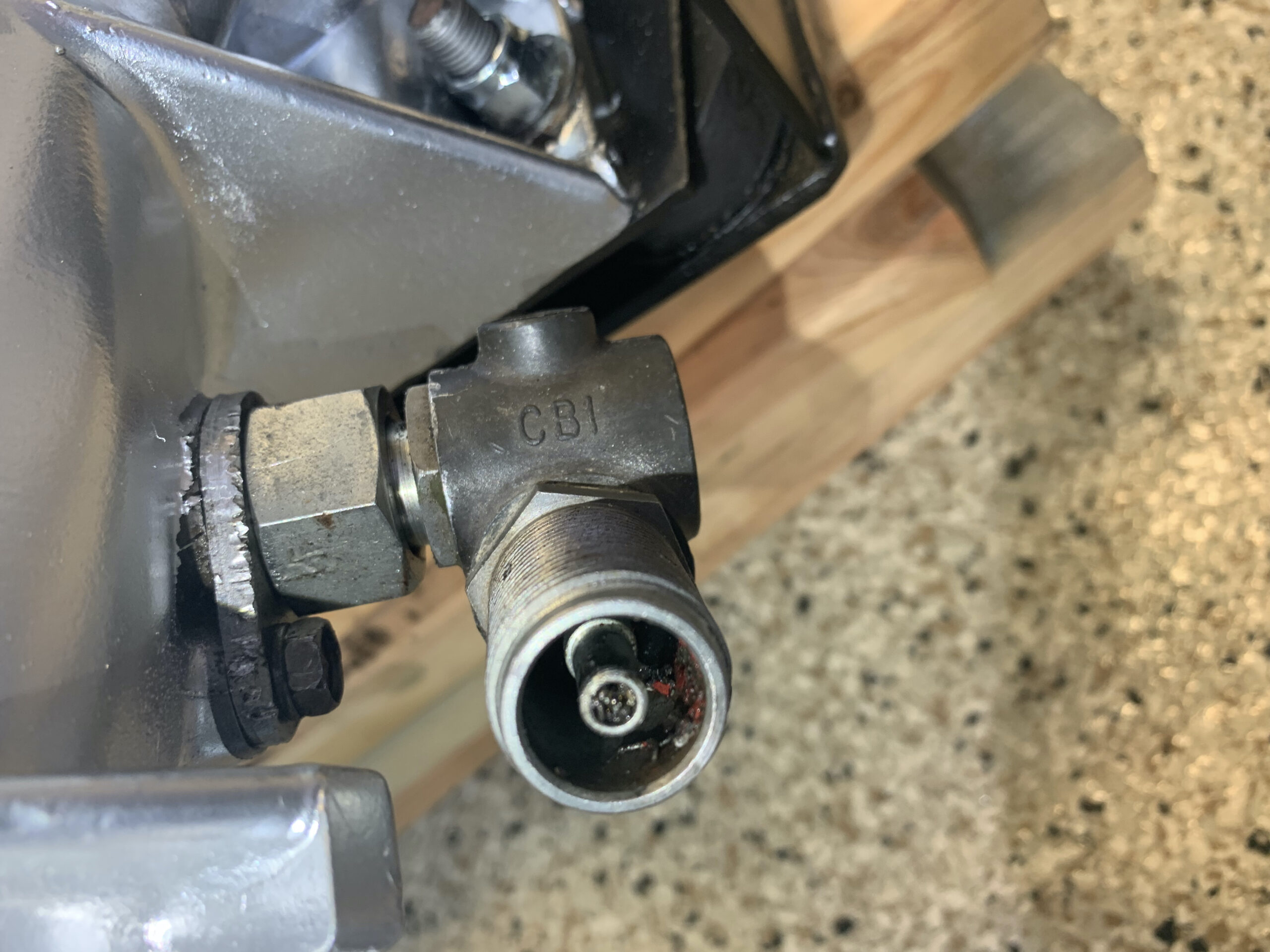
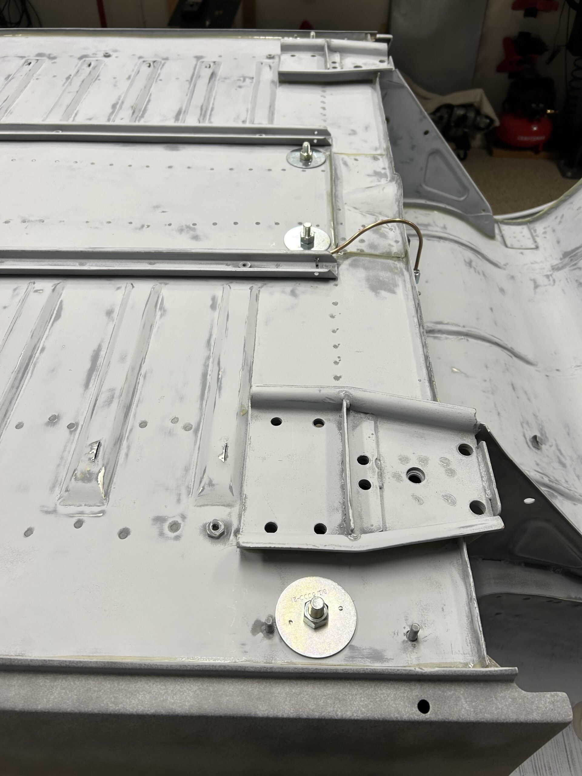
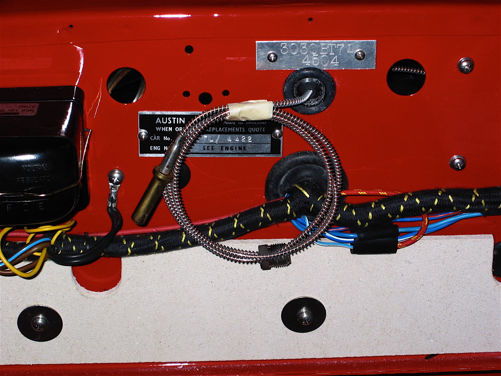
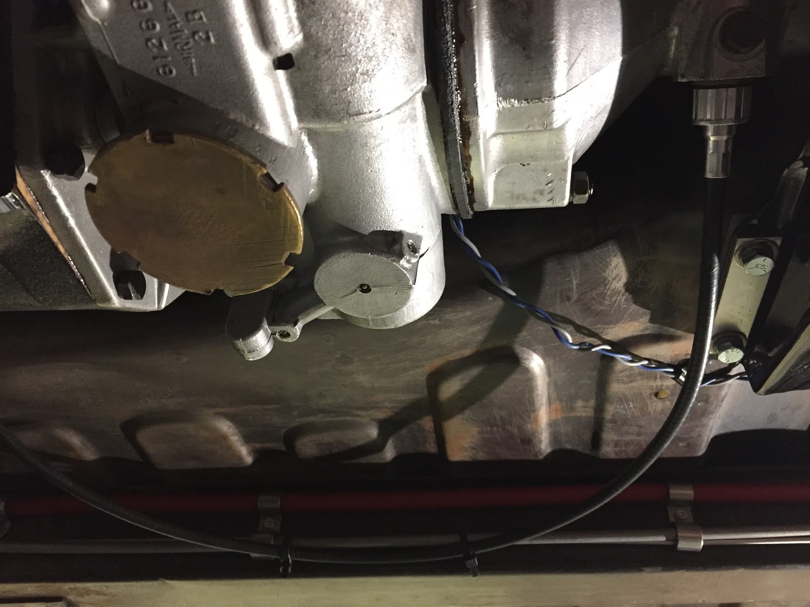
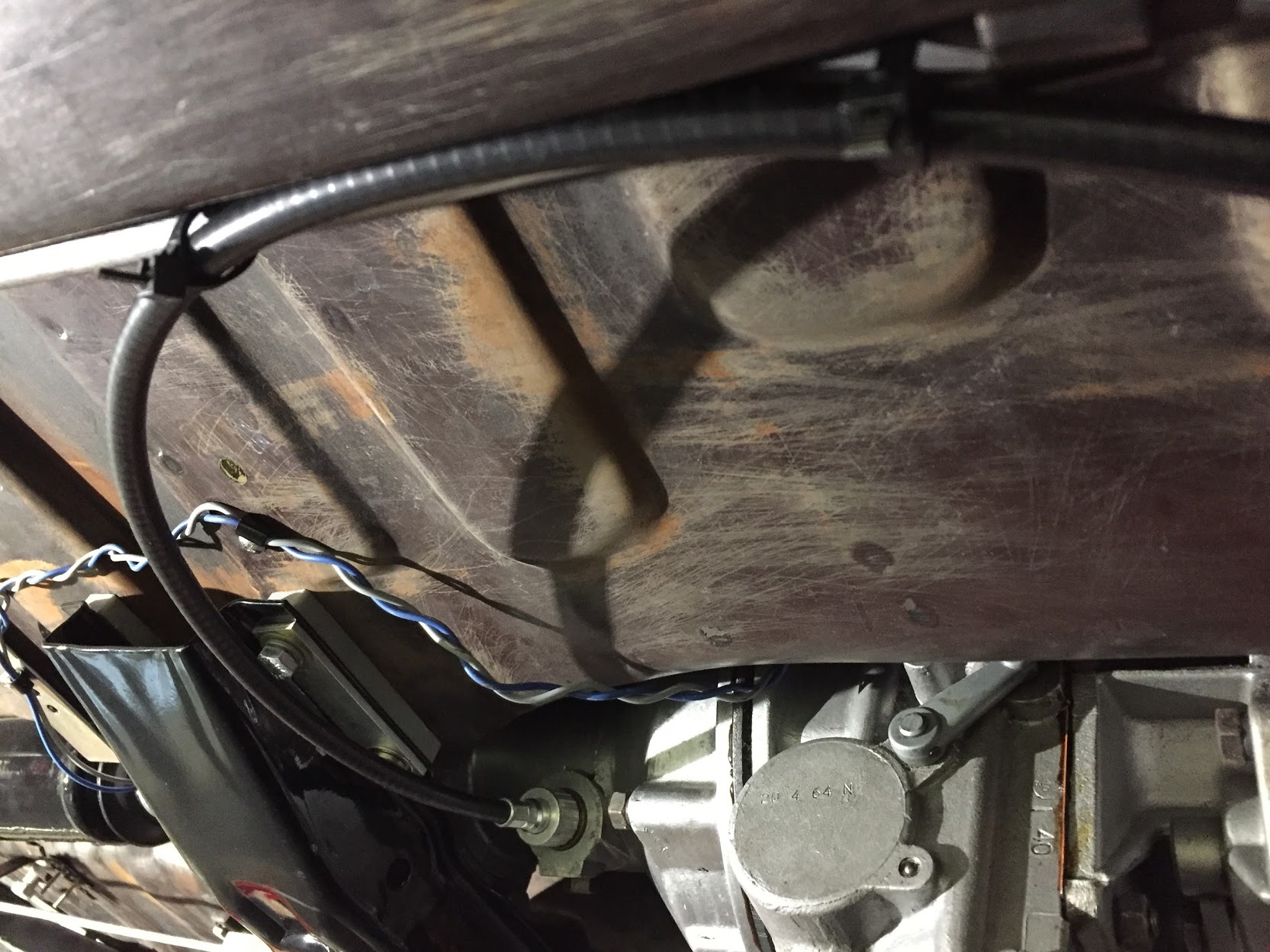
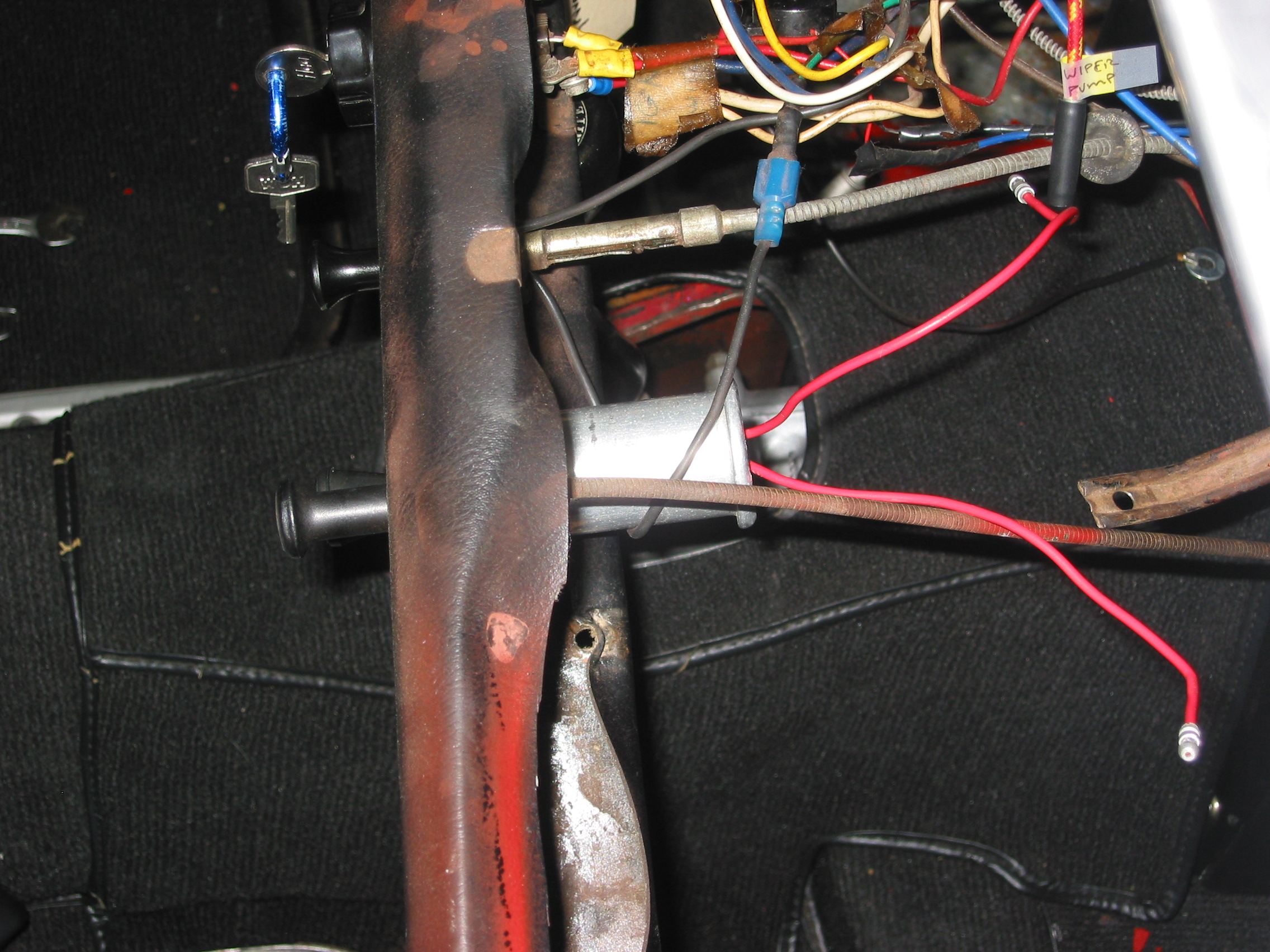
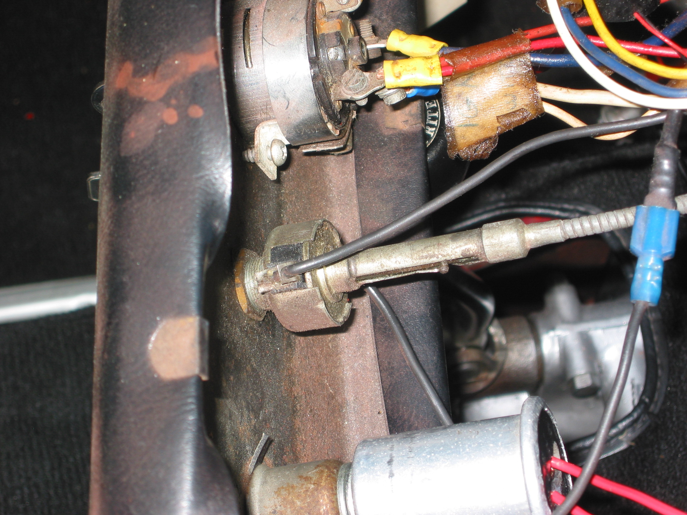
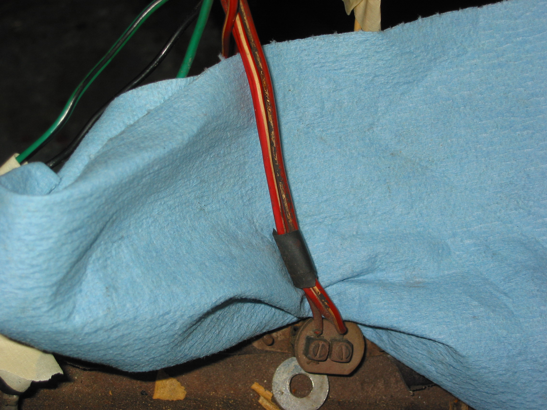
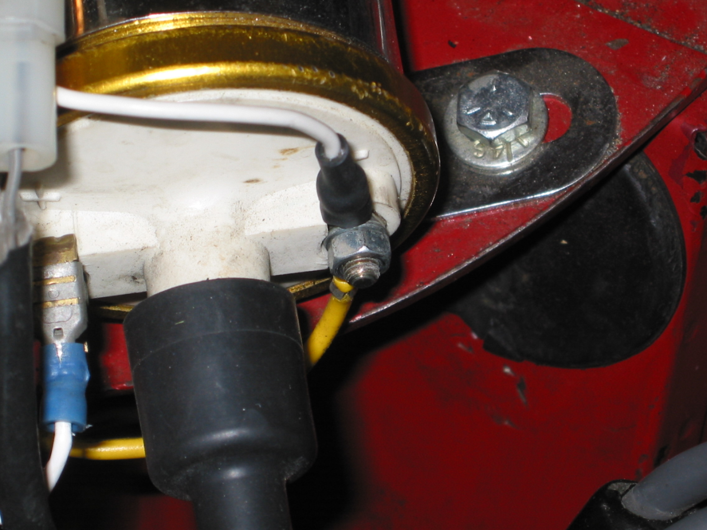
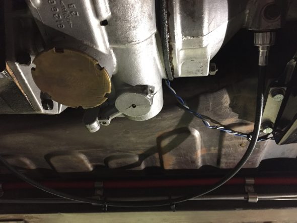
As part of the preliminary install process I added the new speedometer cable – 96″ variety in the engine bay. It is secured by one clip just above the steering column. It is then routed over the top of the gearbox to the passenger side of the car. I have researched how the cable is to be properly secured under the car as it routes to the fitting on the gearbox, but as of December 2016 I have yet to learn anything definitive. Consequently, I have temporarily zip-tied the cable to the fuel line along the passenger side chassis rail as seen below. The objective is to mount the cable in such a way that it has direct unimpeded access to the gearbox fitting with no cable binding.
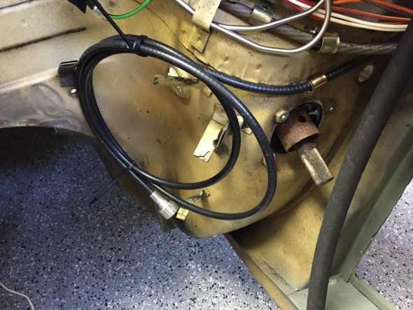
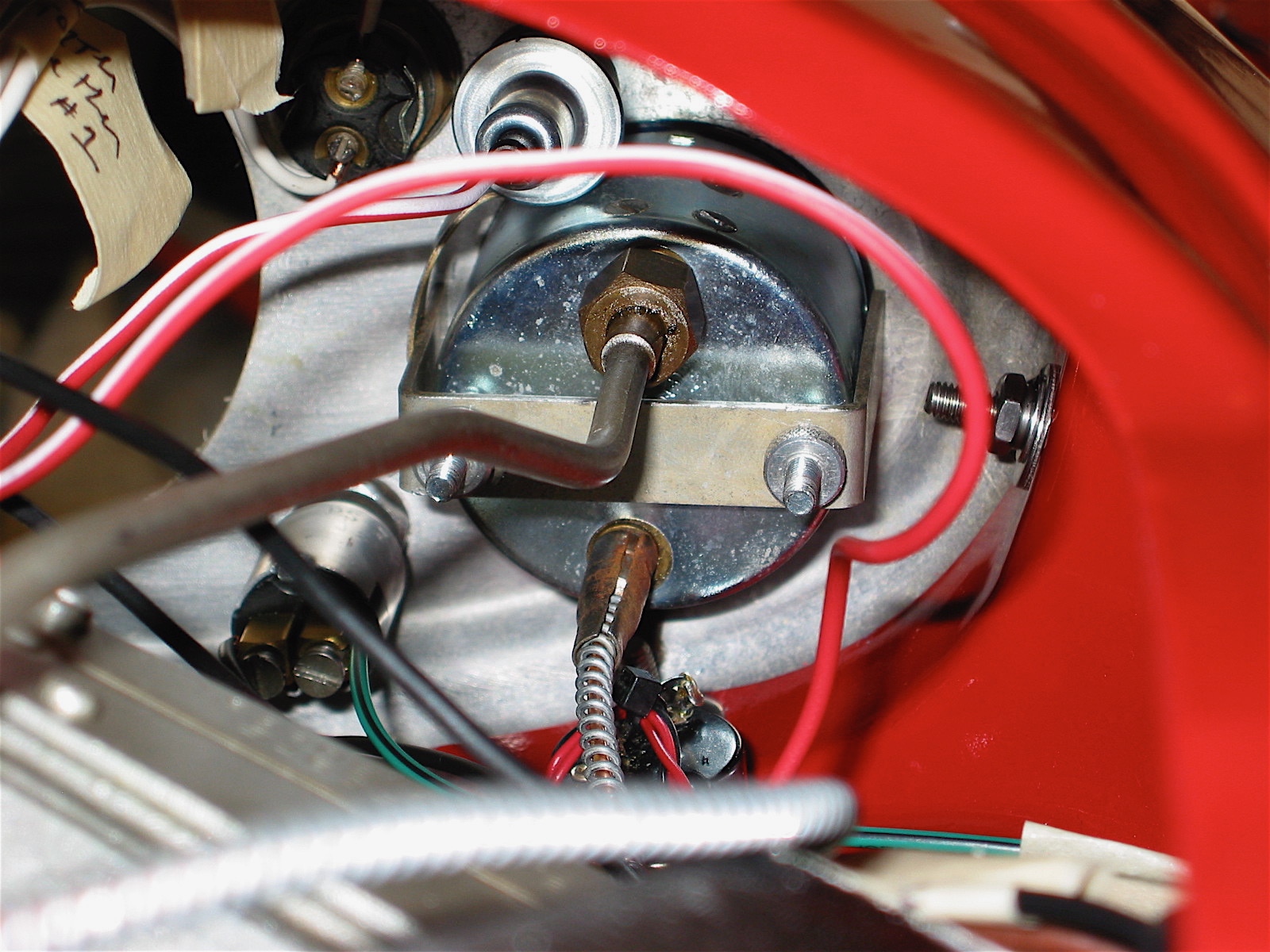
Speedometer Cable Install
Speedometer Cable Mounting

Speedometer Cable Mounting
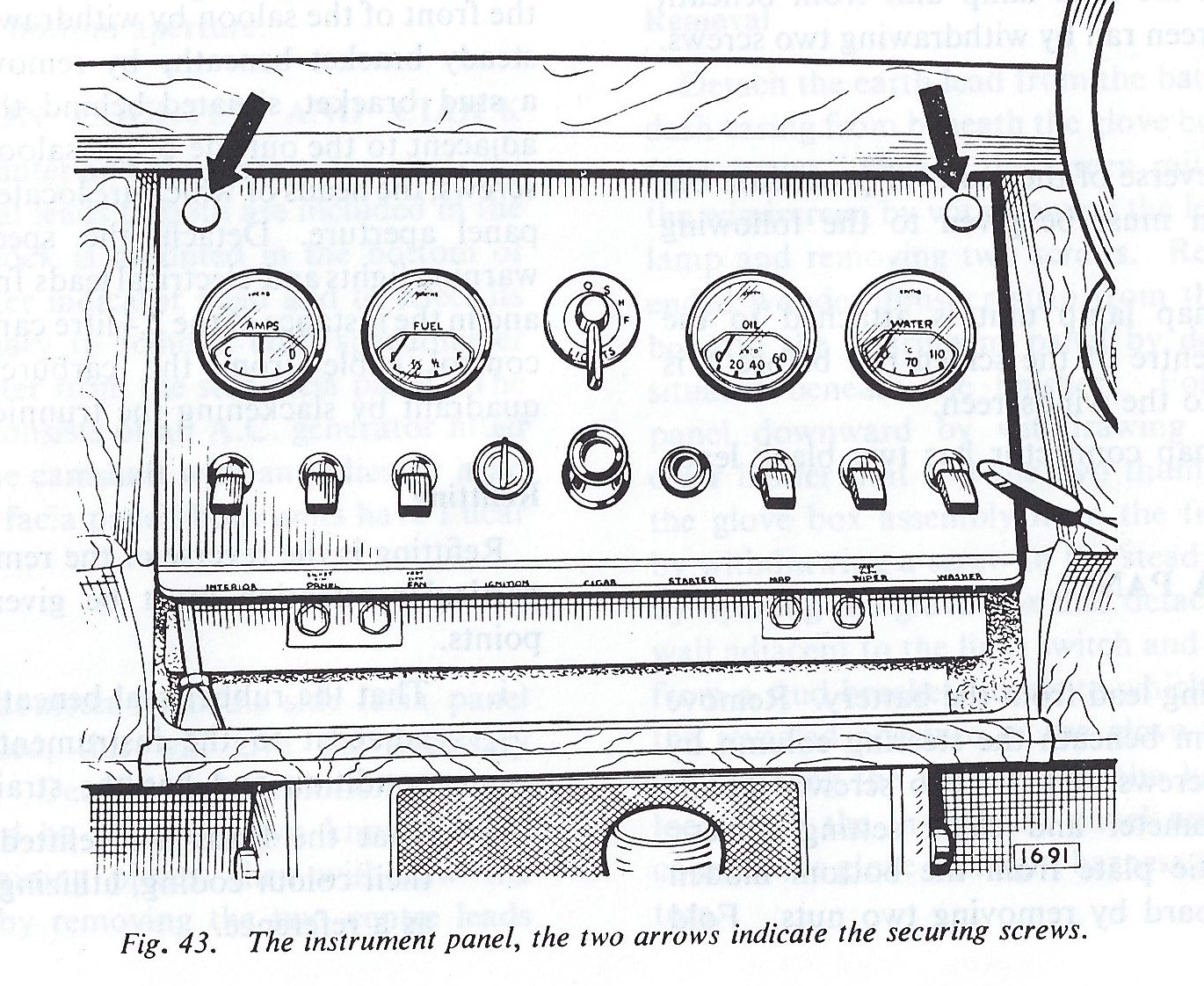
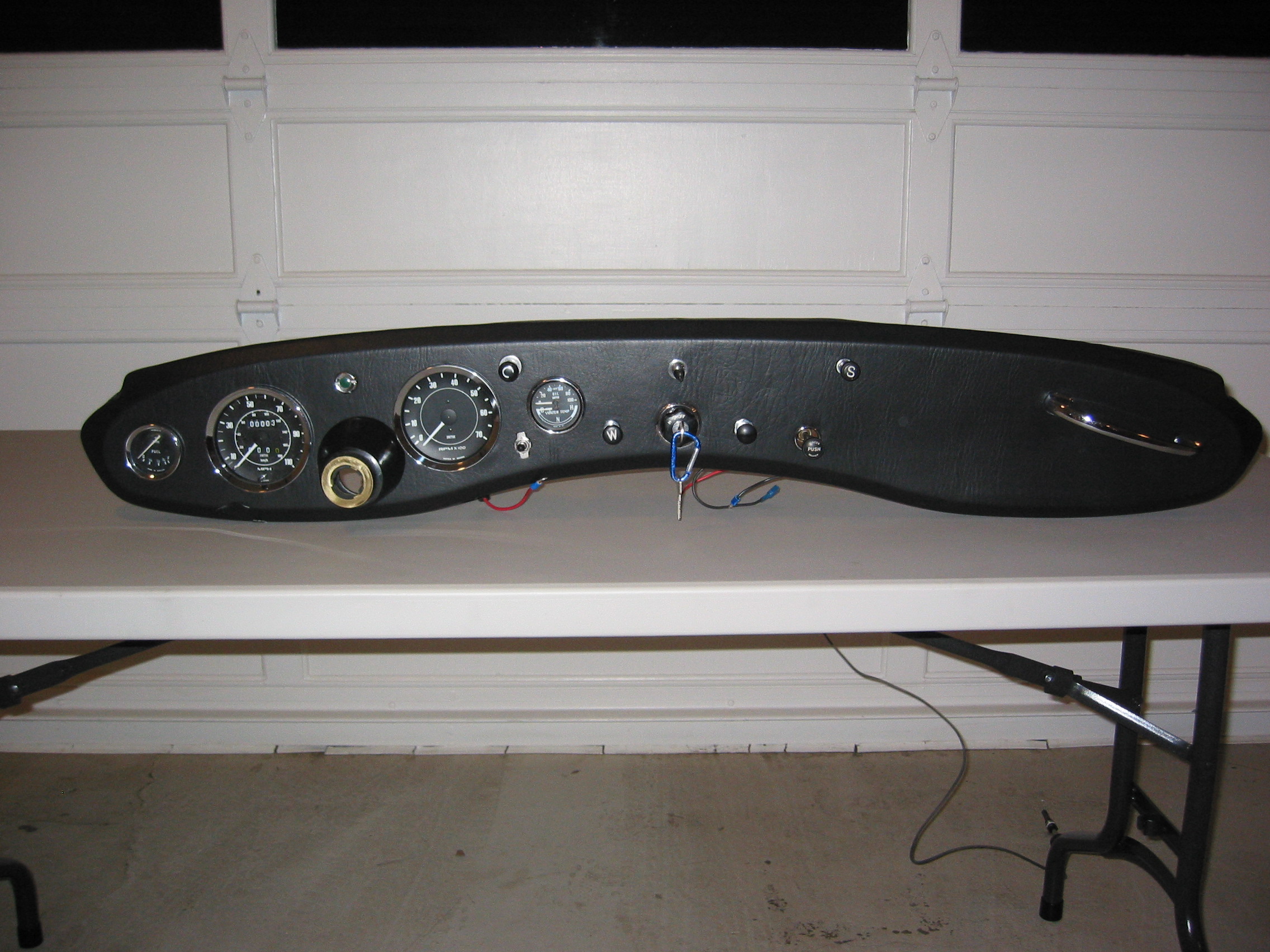
Instrument Panel Assembly
Instrument Panel Assembly
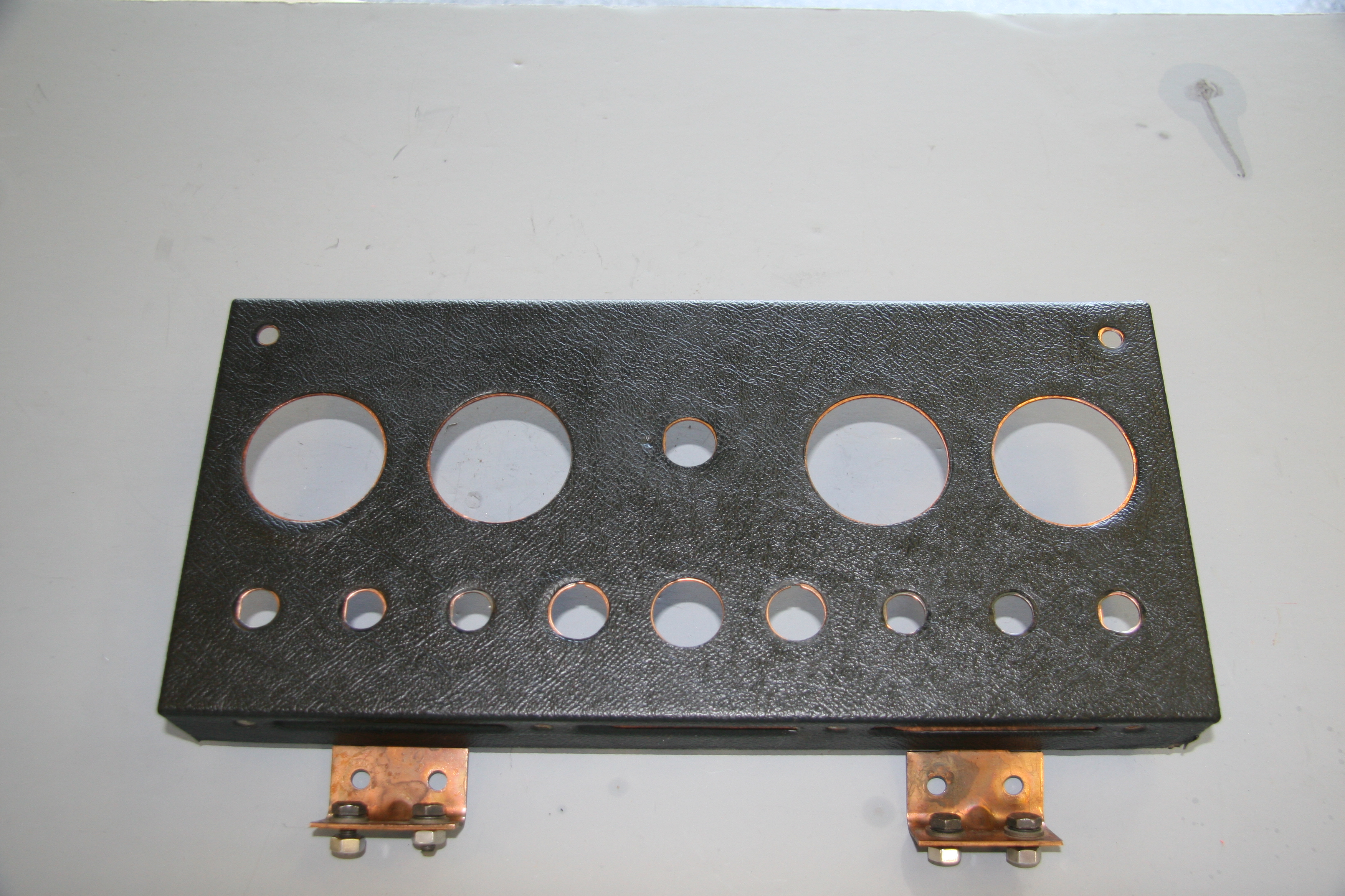
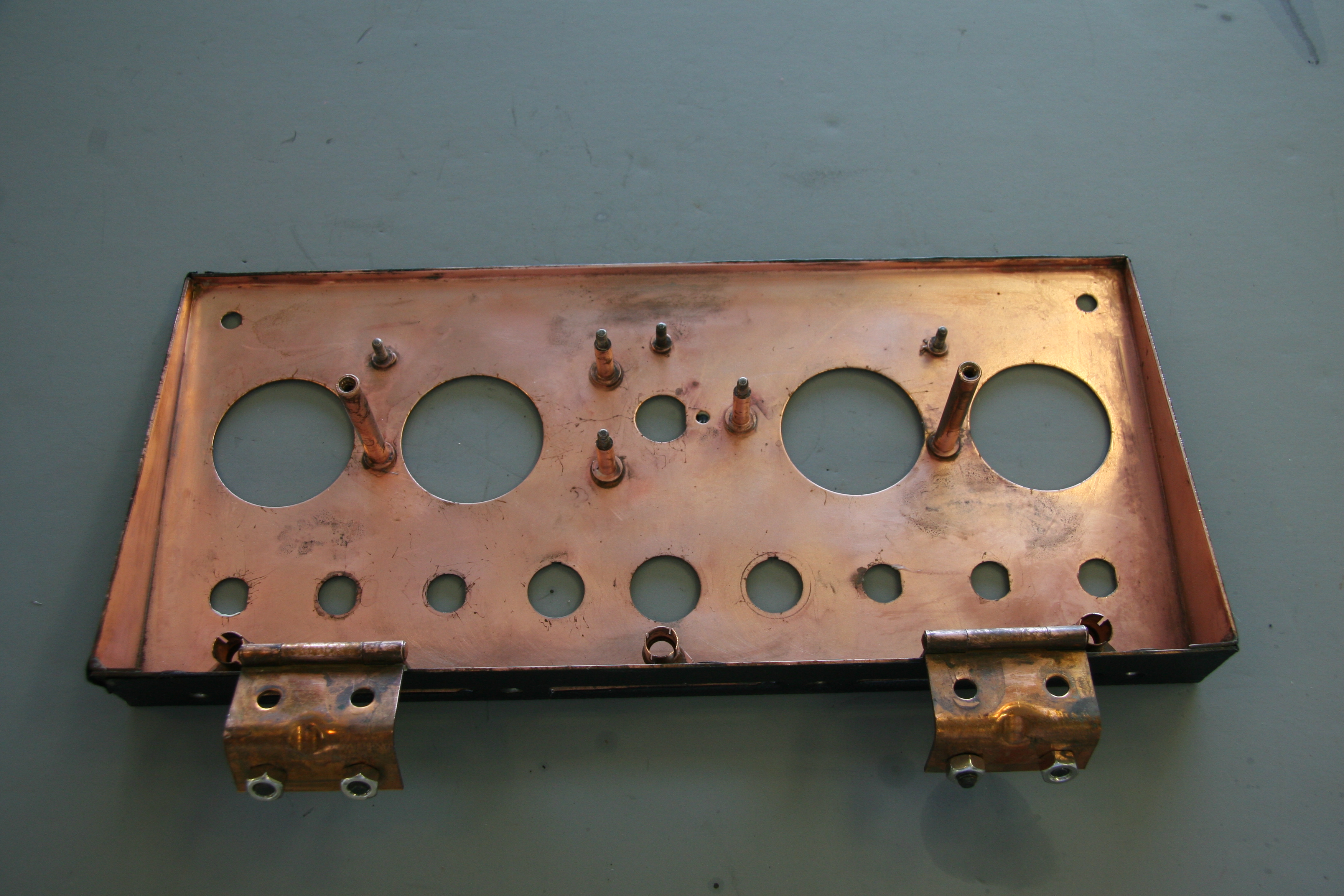
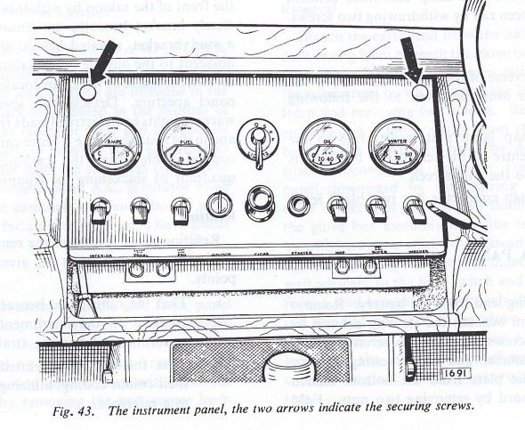
In numerous Jaguar models the interior designers incorporated a handsome centrally-located gauge and switch panel. The panel is made of pressed steel with a copper bath and is hinged at the lower edge of the panel. The hinges are mounted to fixed nuts in the bodywork by four 1/4″-24 x 1/2″ hex head bolts with shockproof and plain washers. Loosening two thumbscrews at the top of the panel makes it possible to easily rotate the panel to access the wiring for the gauges and switches at rear of the panel.
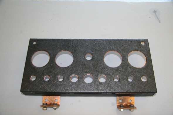
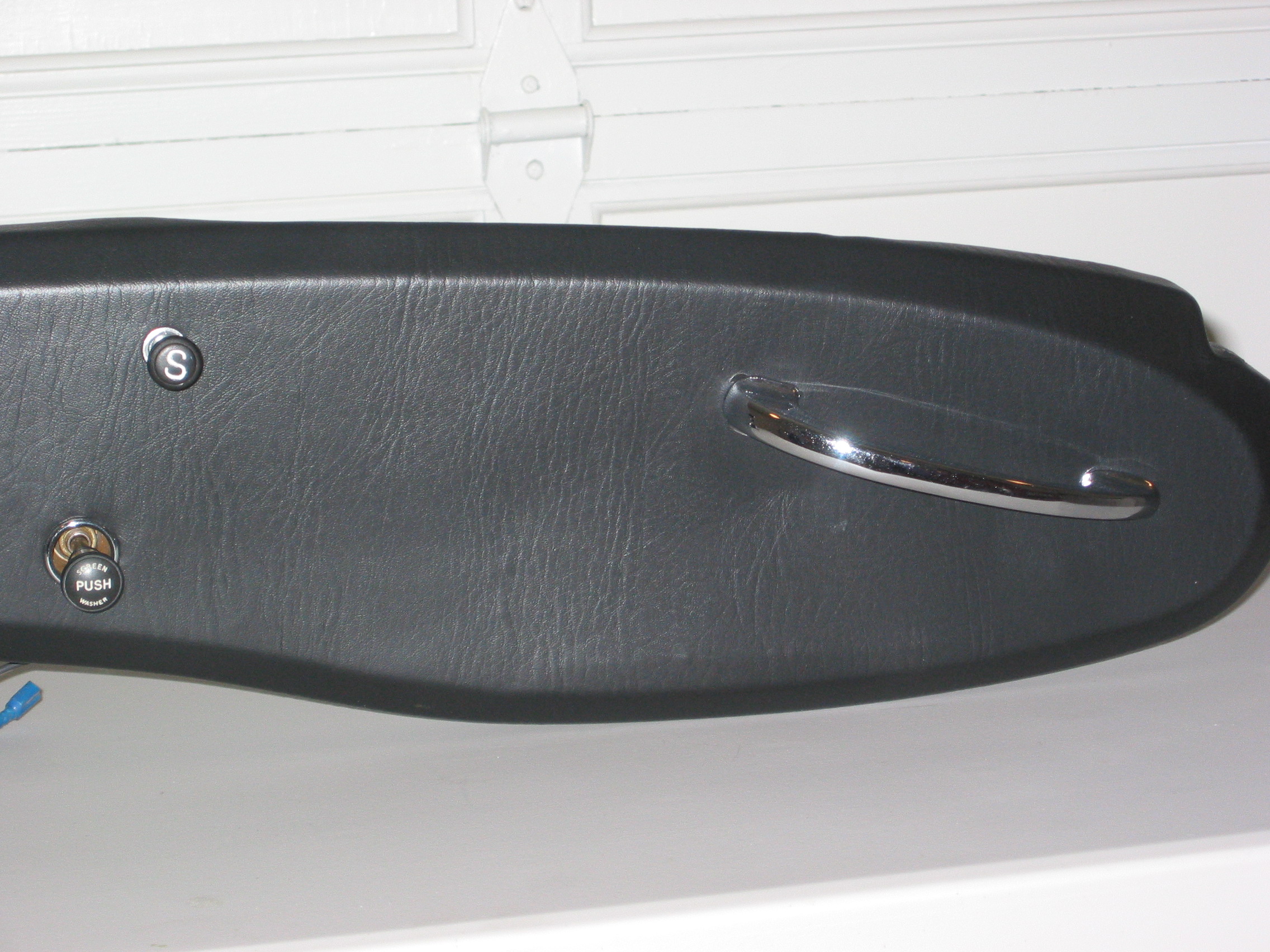
Instrument Panel Assembly Face
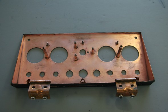
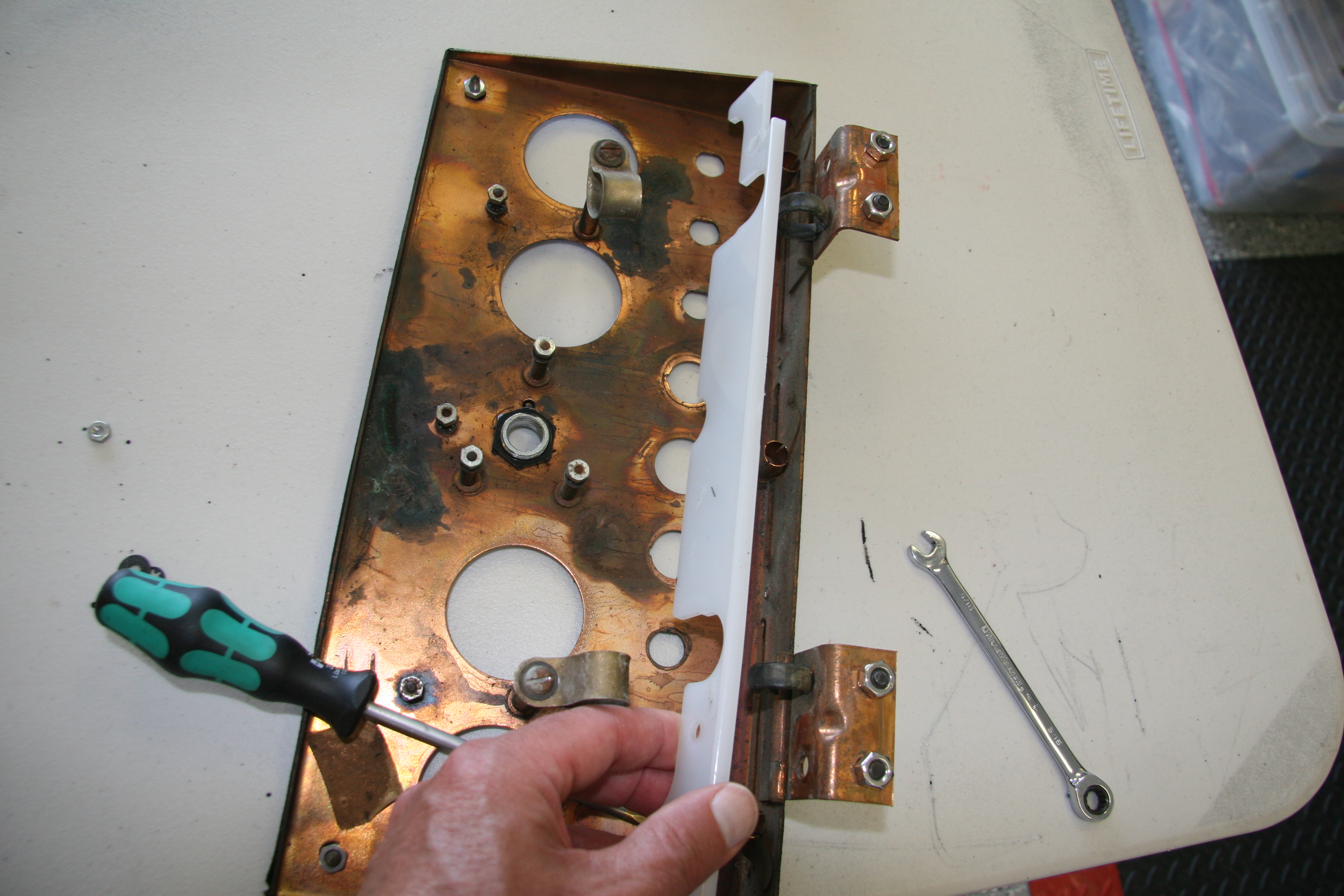
Instrument Panel Assembly
Following the removal of all of the toggle switches and instruments I cleaned the panel assembly. Amazingly the vinyl material on the face of the panel was in very good shape. However, I decided to replace it with a similar material sourced from Aldridge Trimmers in the UK. I did so because I plan to cover the mounting panel for the air conditioning central vents, located immediately below the instrument panel, with vinyl and I want the materials on the two panels to match. The vinyl was secured to the panel with 3m Super 77 spray adhesive.
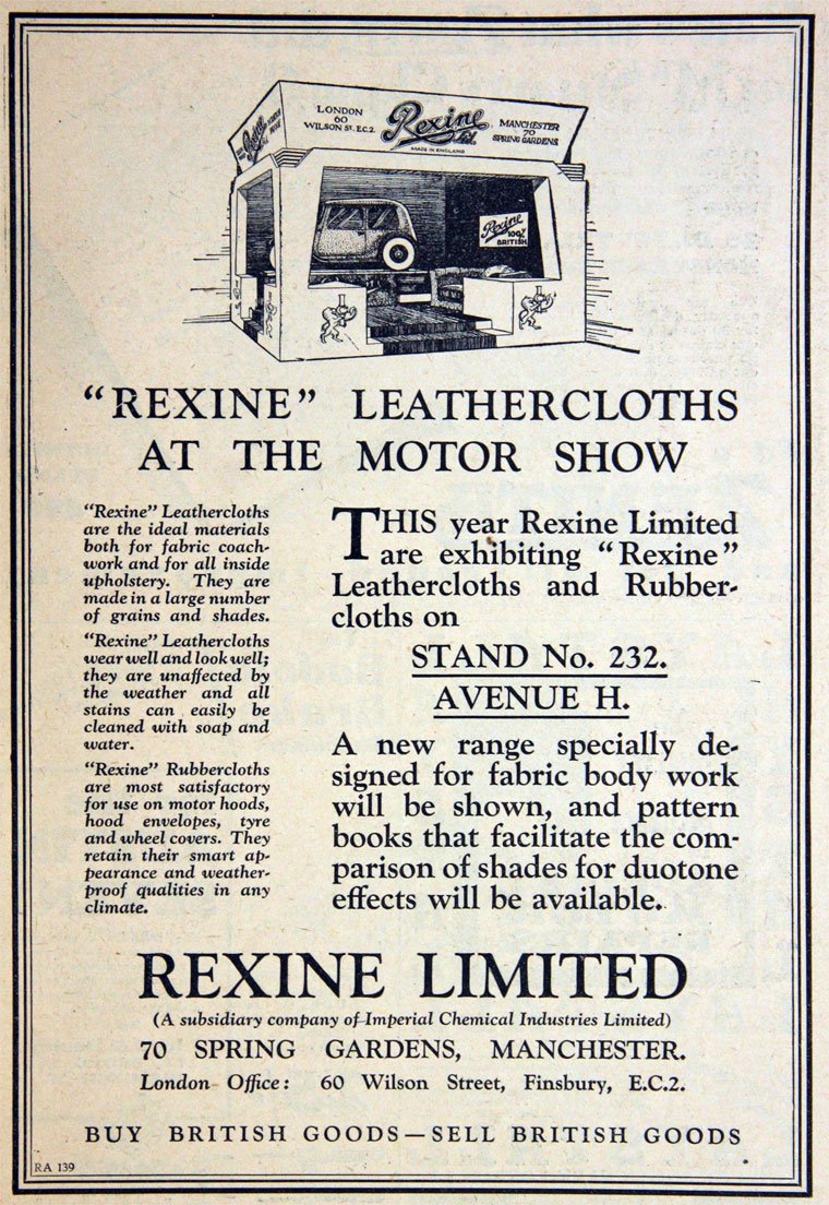
While not the same as the original Rexine Leathercloth, the grain is almost identical. Eric Kriss researched the Rexine product determining that is was made by Rexine Ltd. of Hyde, England. The leathercloth was actually cloth “impregnated with cellulose nitrate, camphor oil, pigment and alcohol and then embossed to look somewhat like leather.” Eric located this wonderful advertisement for Rexine:

The lighting and identification label strip for the toggle switches is comprised of several components.These images show the diffuser screen after clean-up.
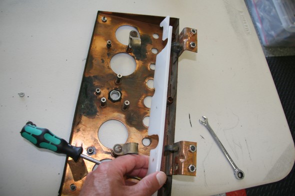
Diffuser Screen
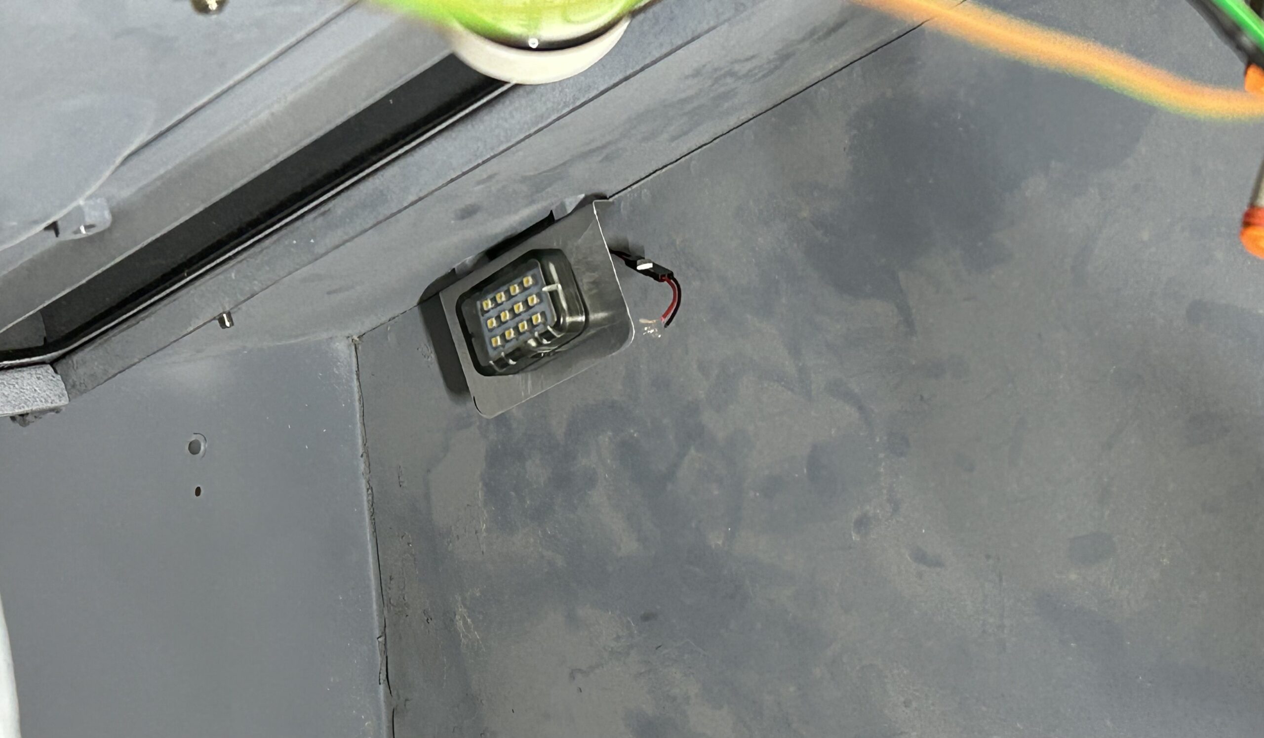
There are three bayonet style bulbs spaced evenly along the bottom of the panel assembly. I have replaced these incandescent bulbs with BA7 LEDs.
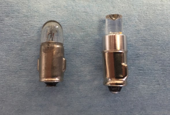
2 Watt Liliput bulb and replacement BA7LED white micro bayonet bulb
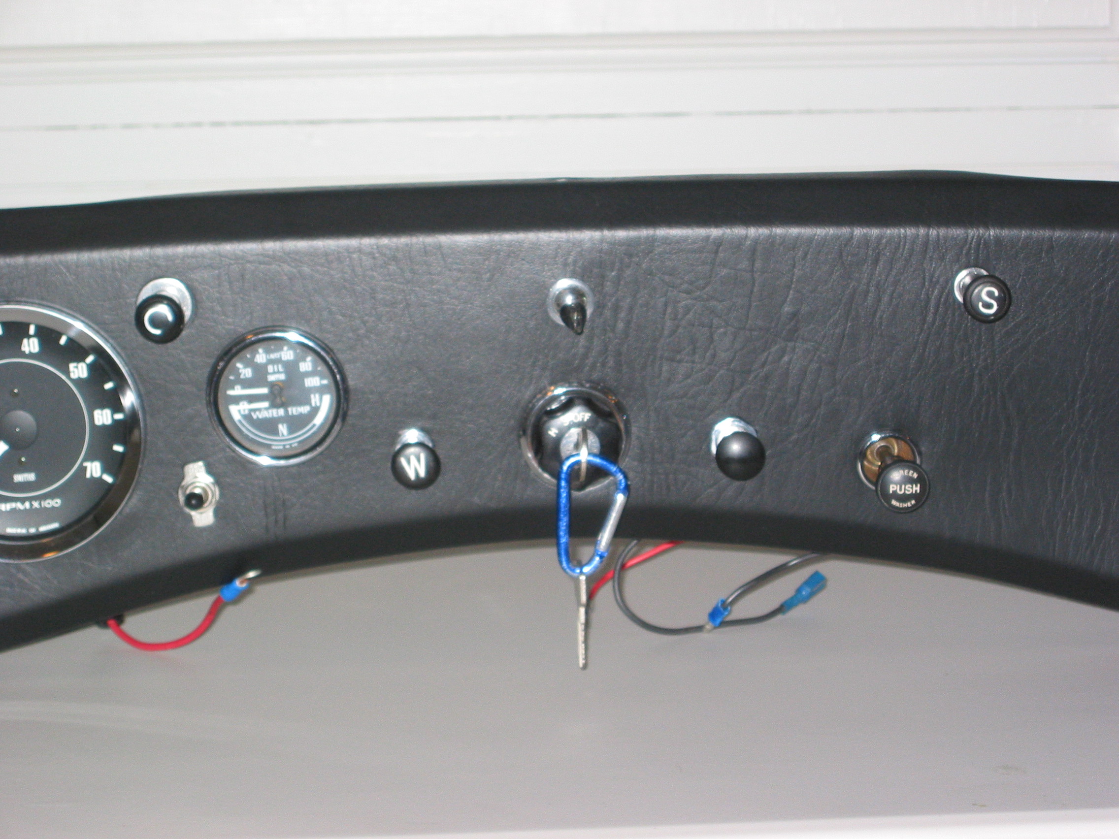
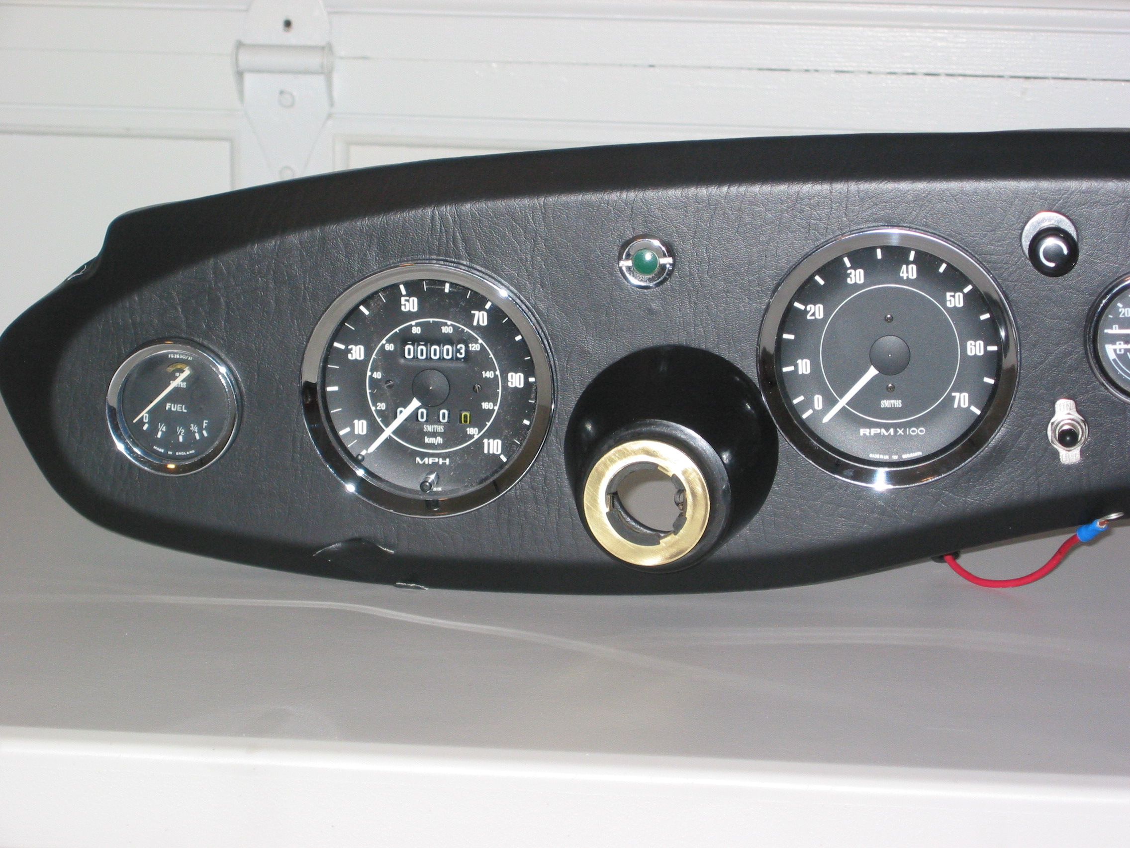
This is an image of my finished instrument panel assembly showing the new vinyl, restored gauges and switches:
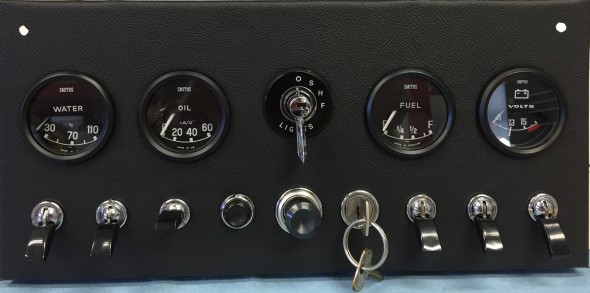
MK2 Instrument Panel Assembly
As one can see, the panel includes four gauges: an electric water temperature gauge, an electric oil pressure gauge, an electric fuel gauge and a voltmeter. The car originally had a ammeter in the place of the voltmeter, but since I converted my car from the original dynamo (generator) to and alternator it made much more sense to install a voltmeter to monitor the electrical system.
Instrument Panel Assembly Gauges
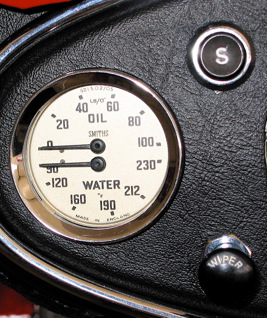
Water Temperature Gauge
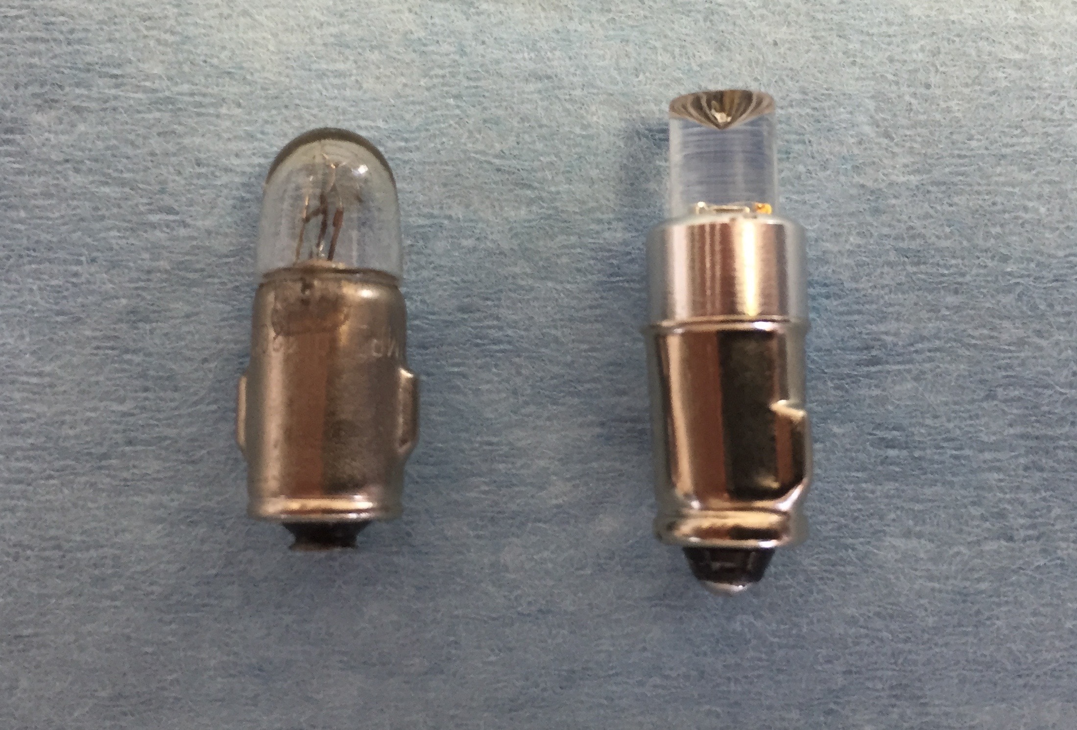
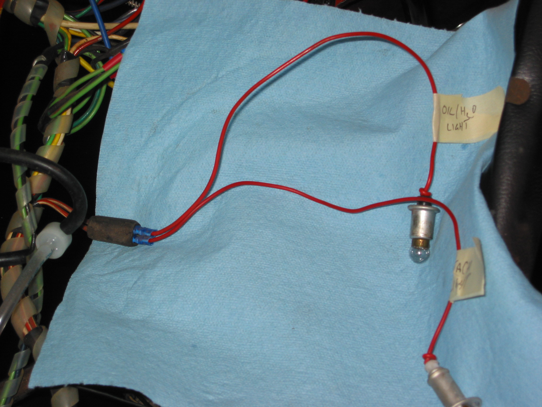
The Smith’s electric water temperature gauge has two electrical terminal connections. One, for voltage to the gauge sourced from a solid state voltage regulator (stabilizer) located behind the instrument panel, and the second, for the temperature input from the sensor located in the intake manifold. The voltage regulator reduces the voltage to the gauge from 12 to 10 volts. The gauge is illuminated by a dedicated BA9ES White LED, replacing the original incandescent bulb. The blue filter was removed from the gauge to provide an improved white light. The image below shows the original incandescent gauge light bulb and the BA9ES White LED now used in each of the gauges.
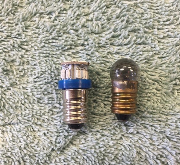
Original Incandescent Gauge Light Bulb and BA9ES LED
Oil Pressure Gauge
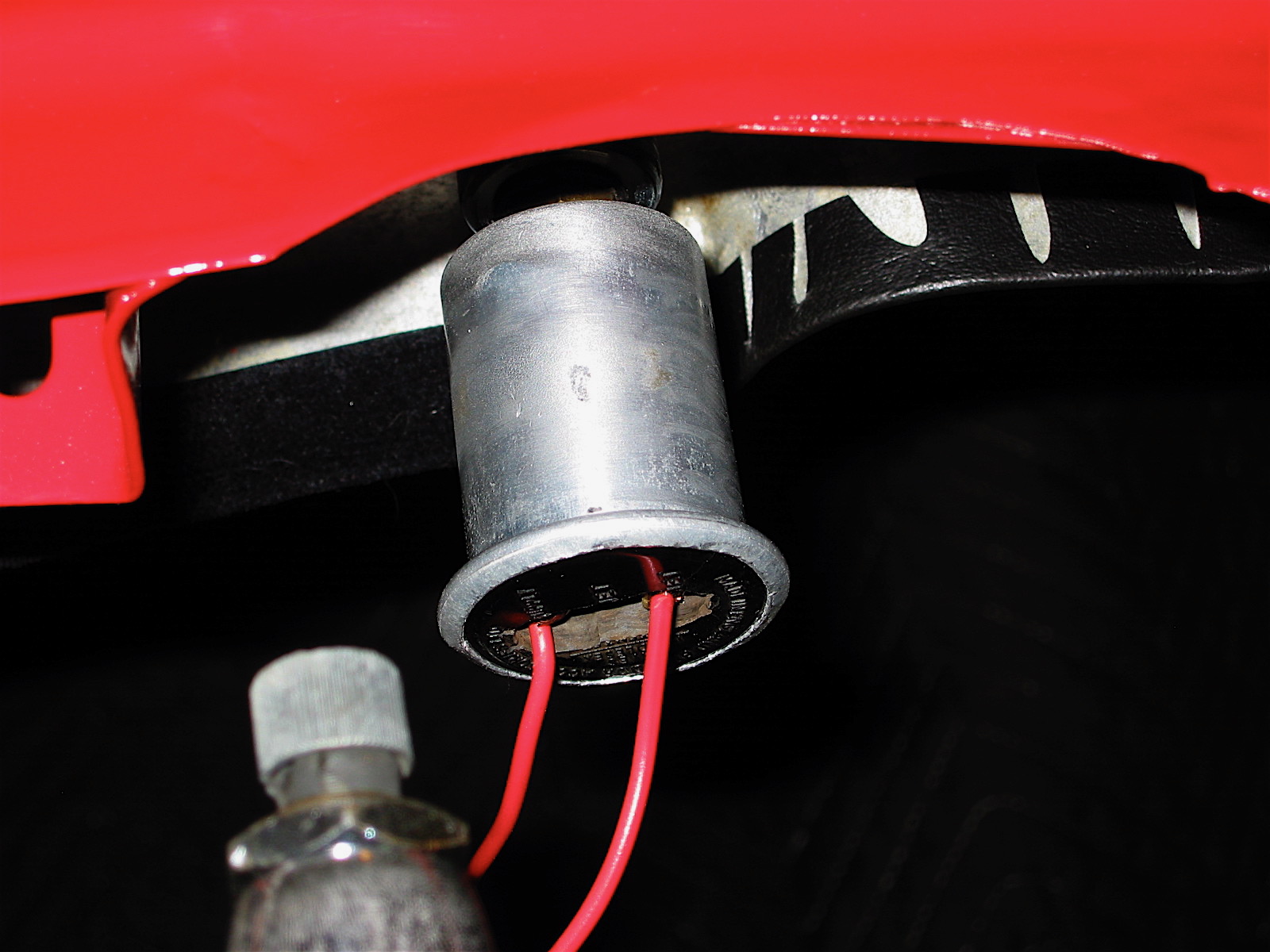
The Smith’s oil pressure gauge assesses pressure up to 60 psi. The gauge has two electrical terminal connections. One, for voltage sourced from the 12 volt terminal on the voltage regulator, and the second, for the pressure input from a sensor device (transmitter) located at the oil filter housing. To reduce signal noise for the optional radio, Jaguar incorporated a capacitor (condenser) with the sender. The gauge is illuminated by a dedicated BA9ES White LED, replacing the original incandescent bulb. The blue filter was removed from the gauge to provide an improved white light. Eric Kriss provides an informative diagram on his blog that illustrates the functional aspects of the oil pressure sender:
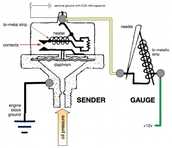
Oil Pressure Sender
Fuel Gauge
The Smith’s fuel gauge works much the same as the water temperature gauge. The gauge has two electrical terminal connections: One, for voltage to the gauge sourced from a 10 volt terminal at the solid state voltage regulator (stabilizer) located behind the instrument panel, and the second, for the fuel level input from the sender located in the fuel tank. The gauge is illuminated by a dedicated BA9ES White LED, replacing the original incandescent bulb. The blue filter was removed from the gauge to provide an improved white light.
Voltmeter/Ammeter
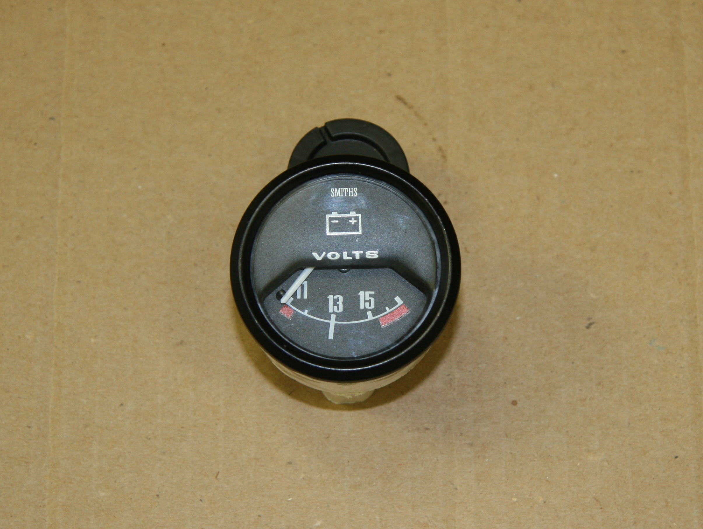
With the installation of an alternator replacing the original dynamo (generator) it makes more sense to have a voltmeter among the dash gauges. So I replaced the ammeter with a Smiths voltmeter sourced from Caerbont Automotive Instruments through Rogers Motors an ebay vendor.
One typically finds the voltmeter with a chrome half-“V” bezel, but Rogers will supply the full “V” bezel to match the bezels on the MK2, and it can be ordered in black. The only problem I ran into is that the black paint on the bezels did not match. The new bezel being too glossy. I took it apart and painted the bezel satin black – still too shiny. I then scuffed it up and repainted flat black – not shiny enough! Finally, I just took the bezel off of the ammeter and fit it to the new voltmeter and now all is well. Getting the black full “V” bezel was an extra $15.00. It comes standard with chrome. If you do what I did, save your extra $15.
The original instruments are in a metal casing. The new voltmeter is plastic. The bezel on the ammeter rotates and then slips off when the bezel tabs line up with slots in the casing. On the plastic casing you have to carefully bend up the bezel tabs and after installing on the plastic casing bend them down to grip the plastic. On the plastic casing there are no slots for alignment.
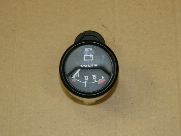
Voltmeter to Replace Ammeter
These are the installation instructions provided with the gauge:
Voltmeter Installation Instructions
Some notes about voltmeters from the mgaguru.com:
“The volt meter is a high resistance low current device which can be connected directly across the battery. In practice you can connect the earth side of the volt meter to any convenient chassis ground point. It is a good idea to connect the signal side of the volt meter to a circuit which is switched by the ignition switch, so it will be disconnected from the battery when the car is parked. It is convient to connect it to the output side of the ignition switch.
Connect the volt meter + and – terminals to battery + and – respectively. If you get it wrong the meter will peg on zero with power on. When correct it read near mid scale, hopefully a bit above 12 volts with engine running. When you blow the horn it will dip just slightly lower. When you crank the engine for starting expect the battery voltage to drop noticeably lower (hopefully not below 10 volts).
Additionally the volt meter can give you indication of the state of charge of the battery. Switch off all lights and accessories, switch off the engine, and switch on the key without starting the engine. If the volt meter reads 12 volts or more the battery is near full charge. If the volt meter is showing much less than 12 volts, then either the battery is somewhat discharged, or the battery is failing and in need of replacement.”
Switches and Other Panel Components
The instrument panel assembly includes six toggle switches, a rotary light switch, a starter button, the ignition switch and what Jaguar referred to as a “Cigar” lighter. The toggle switches are “off” when switched to their lowest position on the panel.
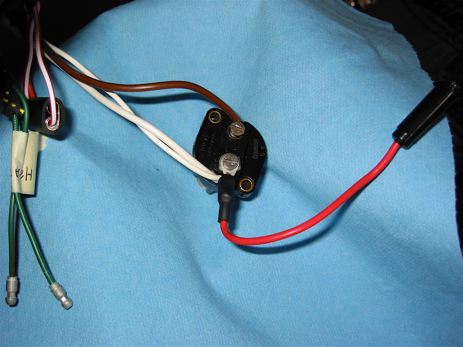
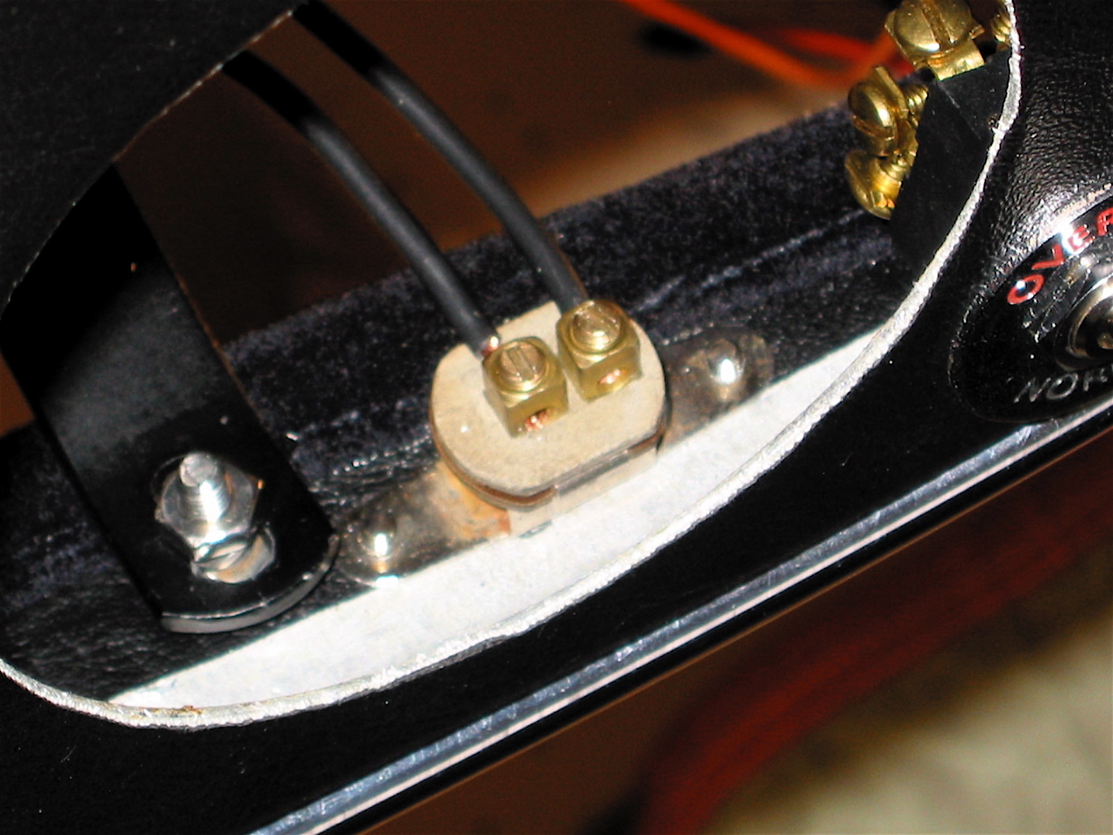
Washer Switch
The washer switch is a momentary switch activated when the toggle is pushed upward. When released the toggle reverts to its lowest “at rest” position. The switch has two electrical terminal connections. One, to ground connected to a post on the back of the panel, and the second, to the washer bottle motor. My original switch was broken so I installed a new one from SNG Barratt.
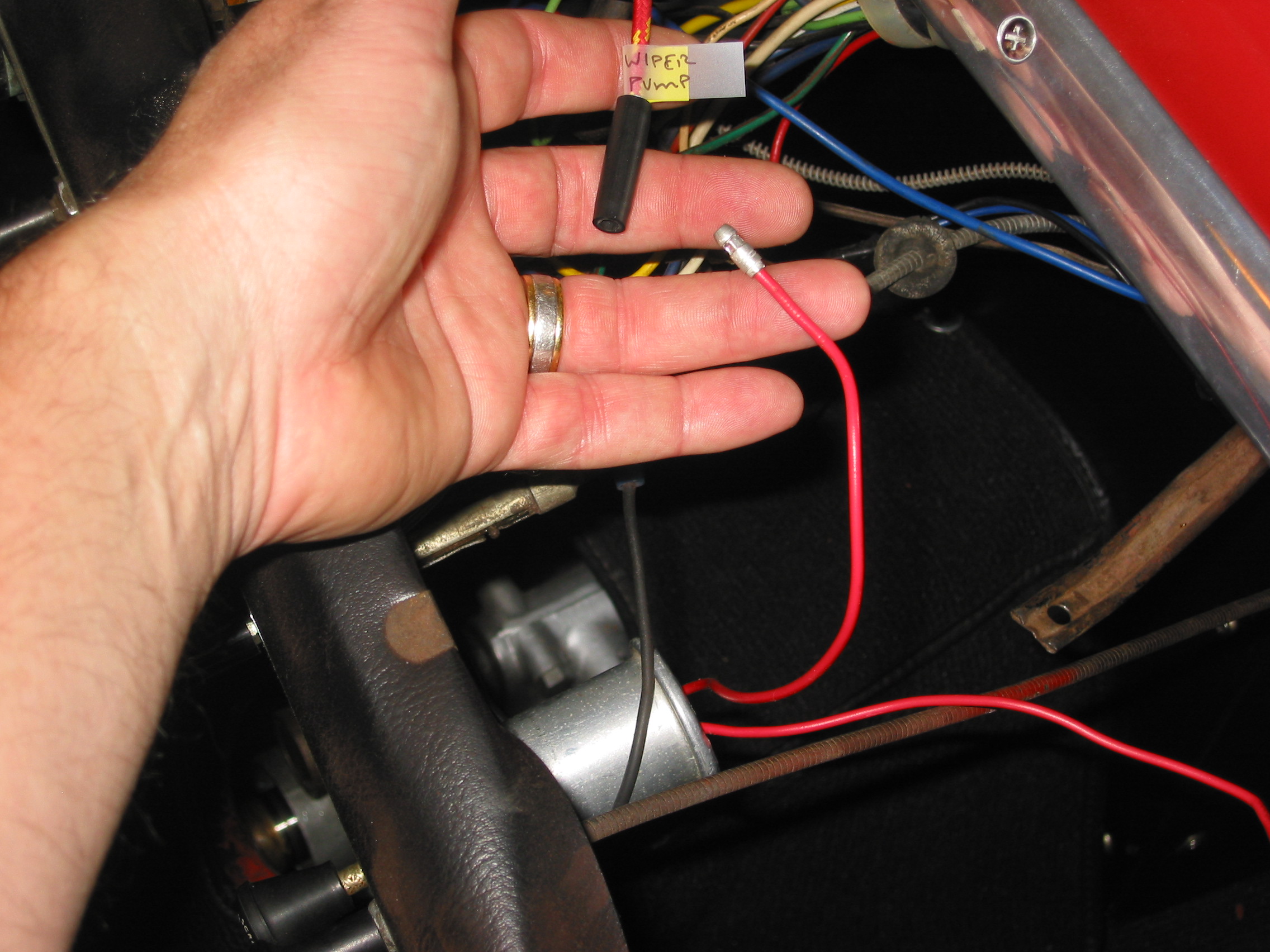
Wiper Switch
I chose to upgrade my wiper motor with a kit supplied by Classic Motor Cars in the U.K. Installation of the wiper system is detailed in another posting: https://valvechatter.com/?p=6612
The kit uses a model 29 W Lucas Motor, part# 75967D that I believe was used for XJ series Jags in the eighties and early nineties with a modified original switch to operate the system. The kit also included new control boxes and a wiper rack cable. There are seven electrical terminal connections on the switch. One, to ground on the back of the panel, another to the fuse panel for power, and the remaining five wires route to the wiper motor for the two speed and park function.
Map Switch and Panel Switch Repurposing
The third toggle switch from the left on the instrument panel assembly was originally designed as a switch to turn on a map light that is provided just under the Screen Rail Capping Assembly (wood dash top). The panel switch (second from the right) was originally intended to alternate the panel lights between bright and dim settings. It is hard to fathom why Jaguar viewed this as necessary given that even the bright setting of the switch still provided grossly inadequate lighting, at least by today’s standards.
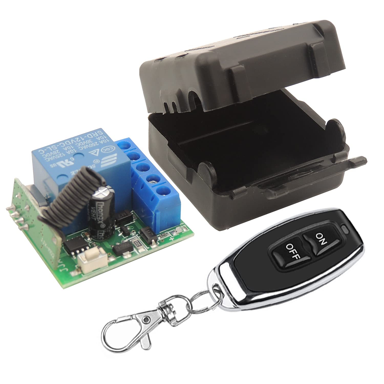
Eric Kriss, in his MK2 restoration, decided to repurpose these two switches to enable the possibility of an integrated hazard (flasher) circuit in his electrical system. With his permission and invaluable instruction I decided to adopt Eric’s modification in my own car.
Therefore, in my MK2, the panel switch sacrifices the bright/dim feature and is repurposed to control the panel and gauge lights as well as the map light. It then becomes possible to utilize the original map light switch as a hazard switch. The panel switch is a three position OFF-ON-ON switch. The middle setting is now used to turn on the three translucent strip edge lights on the panel as well as the gauge lights. The upper setting is now used to also turn on the map light.
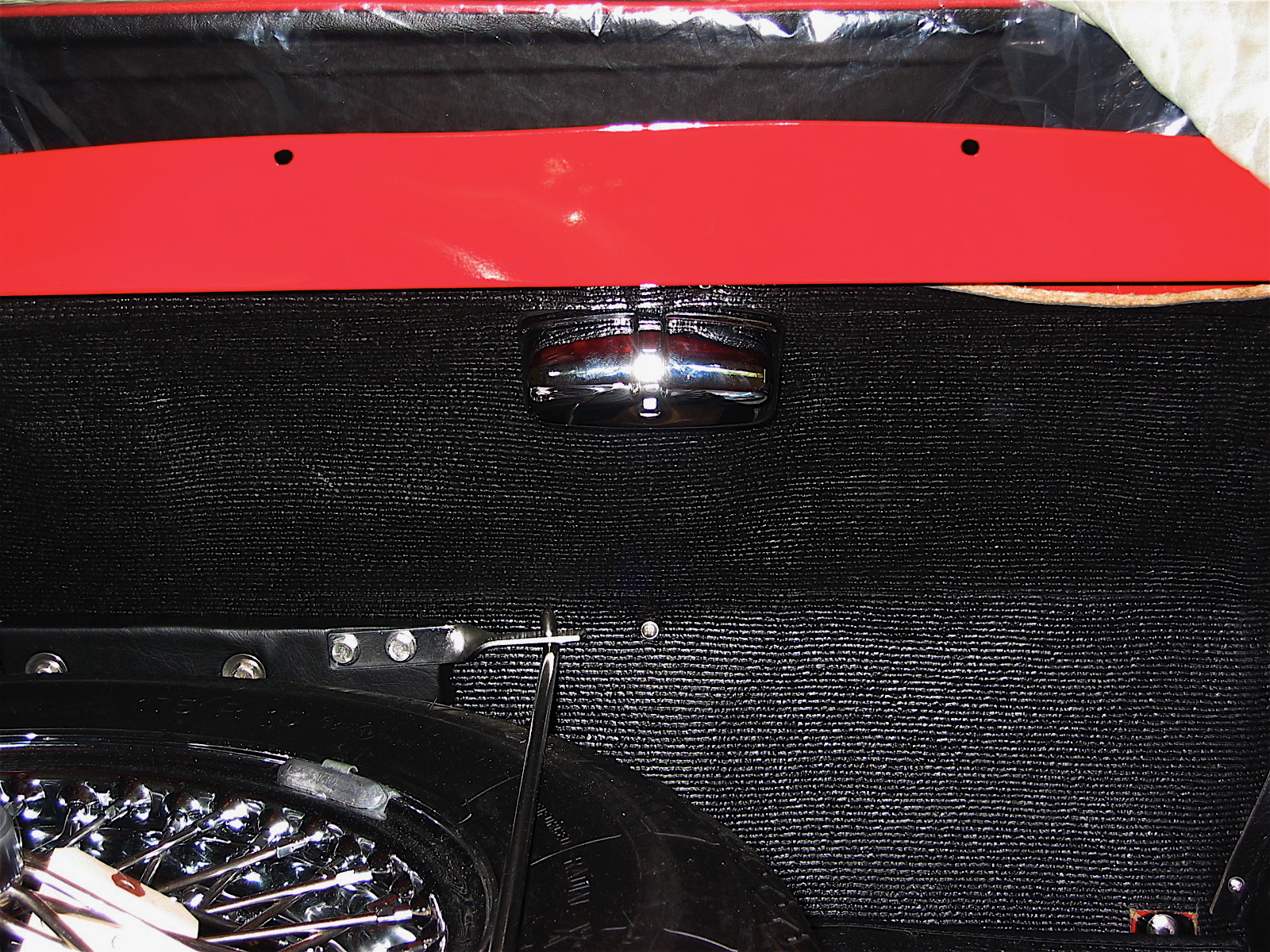
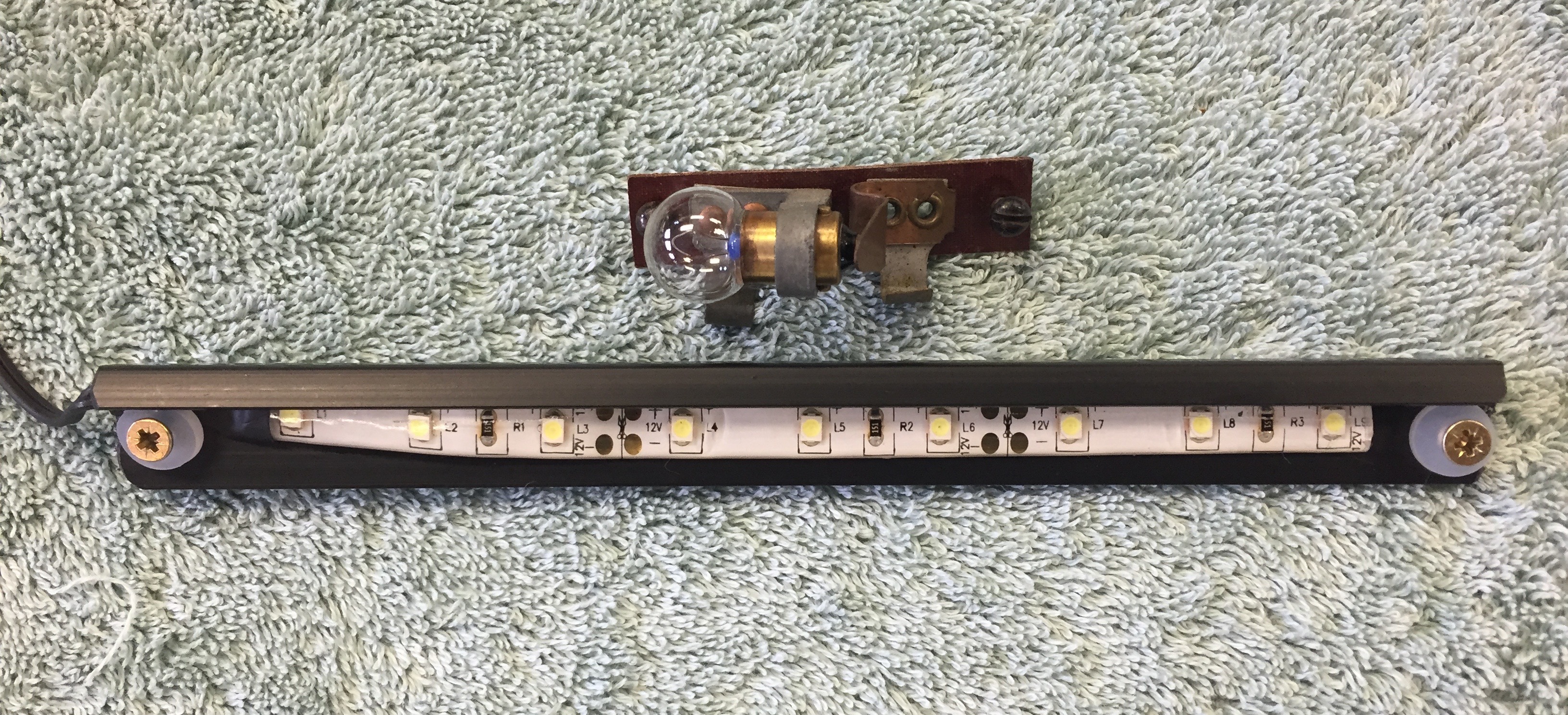
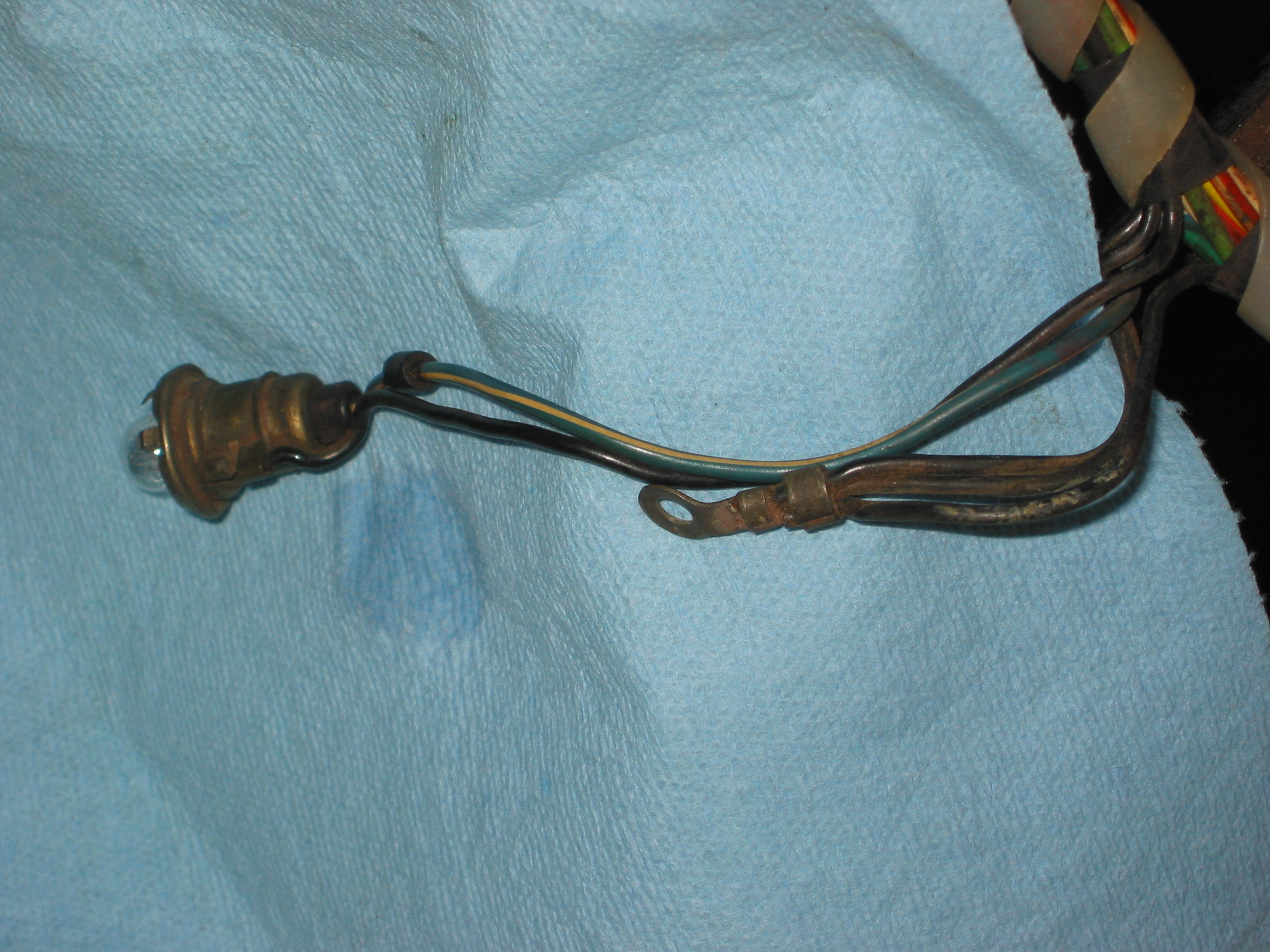
The image below shows the original map light and also the new LED strip that will replace the single incandescent bulb:
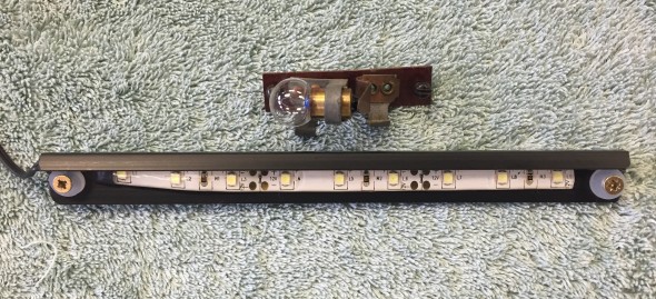
Original Incandescent Map Light and LED Map Light
Terminal #4 on the panel switch is used to connect to the power source at the fuse panel. Terminal #6 connects to the map light and terminal #7 has two wires with one connecting the four LEDs in each of the panel gauges and the other connecting to the three LEDs in the lower section of the panel to illuminate the label strip.
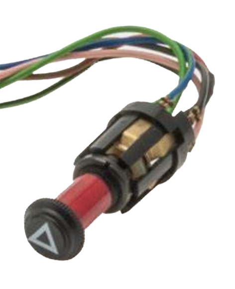
Hazard Switch
As described above the map light switch is repurposed to serve as a switch to activate the hazard flashers. I had actually purchased a new reproduction hazard switch but I never liked that it appeared as an “add-on” device and the warning was a bit complicated. Implementing Eric’s repurposing plan integrates the hazard function into the instrument panel assembly. The wiring connections for the switch are addressed in the post documenting the new wiring harness.
Starter Button Switch
The original starter button was cleaned and reused. The switch has two electrical terminal screw connections. One to the fuse panel, and the second, to the ignition switch at the ING terminal.
Ignition Switch
My original switch functioned just fine, so I decided to just clean it and reinstall. On my ignition switch there are three electrical terminal connections: B+, IGN and ACC. All three are wired to various positions in the Classic technologies fuse panel. The IGN terminal has a double terminal connector to permit wiring to the starter button switch.
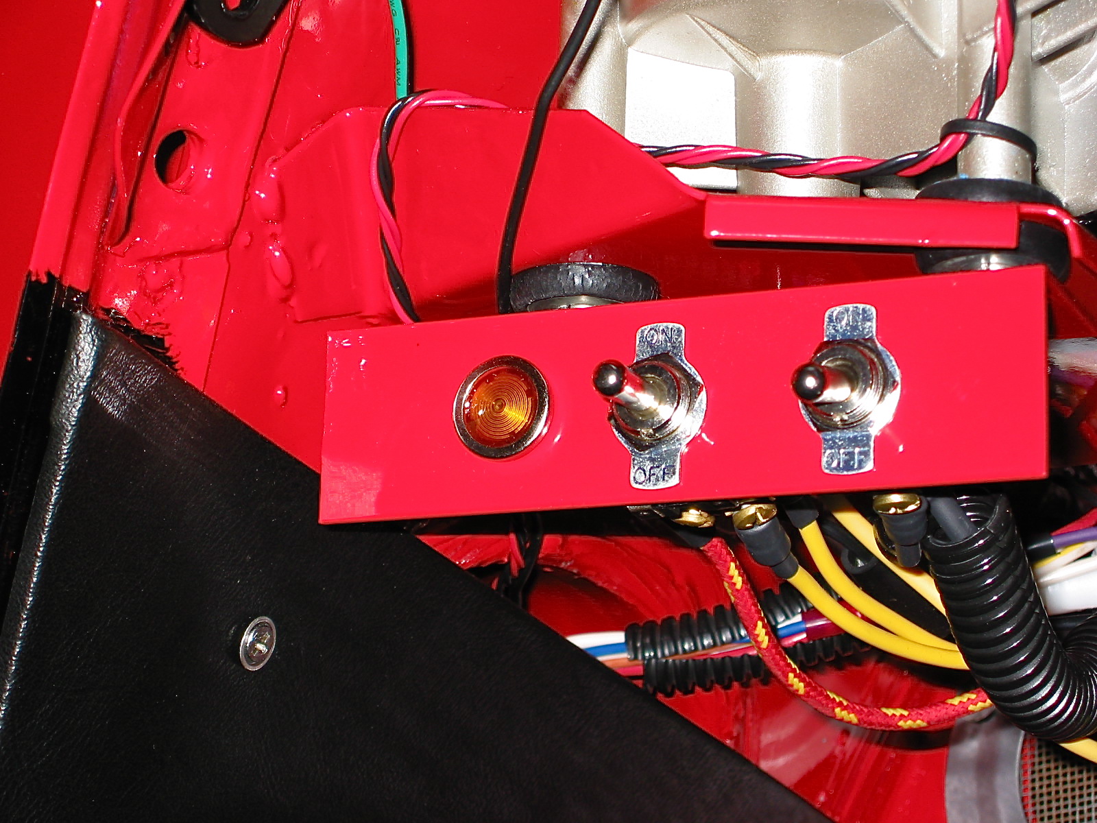
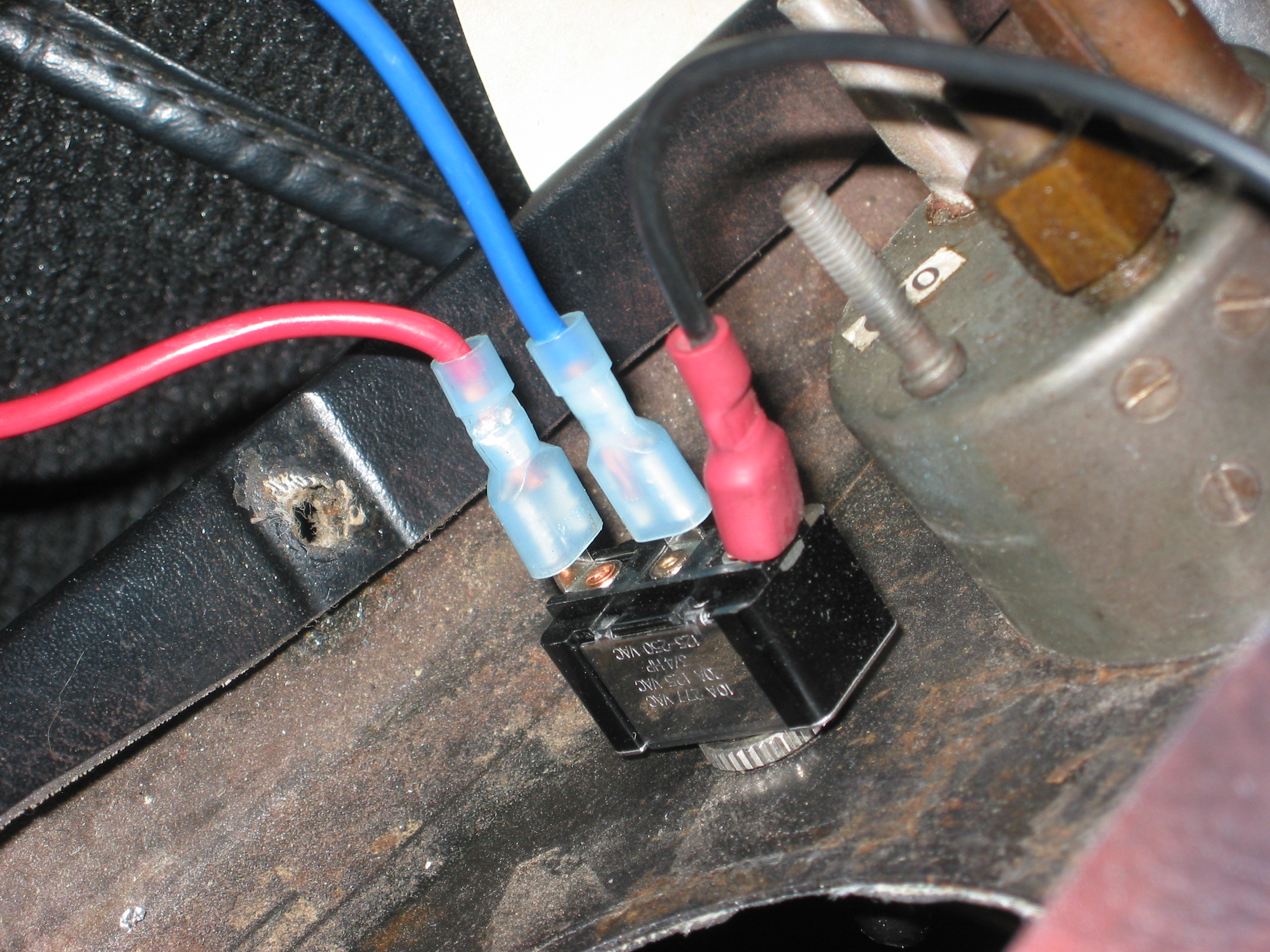
Fan Switch (57SA)
The fan switch has three positions: the lower position is “off.” The middle position is “Low Speed” and the upper position is “High Speed.” The wire to terminal # 4 is the power source. Terminal #8 is the high speed fan connection and terminal #6 is the low speed connection.
Interior (light) Switch
The interior light switch is a simple “ON-OFF” switch. Again, following Eric Kriss’s lead I have modified the interior light circuit. Originally, the switch when moved to the upward position activates the B/C pillar lights as well as the the rear interior lights and interacted with the four door switches. In our modified circuit, the cubby light/switch and the boot light/switch are included. The switch has two electrical terminal connections. One to ground on the back side of the panel, and the second, to the various lights and switches incorporated in the modified circuit. Additional information about the interior lights may be found at the “Interior Lights” post.
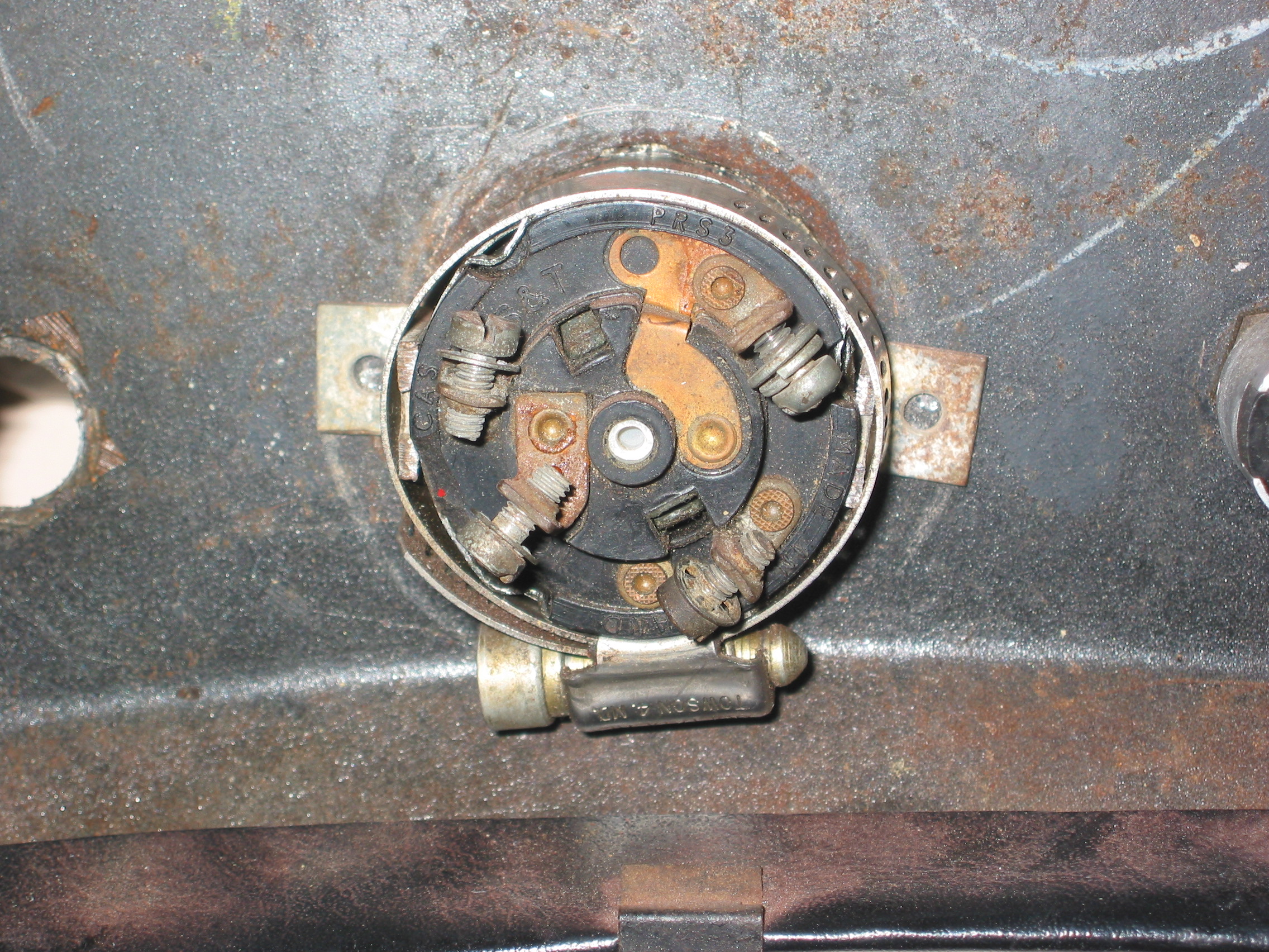
Light Switch
The rotary Lucas three position light switch actually has four settings:
O – Off
S – Side/Tail/License Lights plus others if switched
H – S + Headlights
F – S + H + Foglights
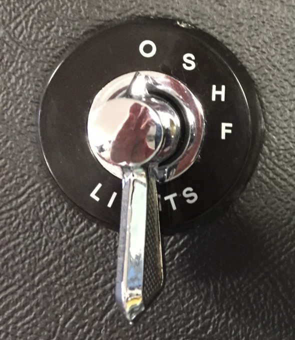
Lucas Three Position Light Switch
Terminal #3 of the light switch has two connections. One, to the chime that has been added in my wiring plan to warn the driver if the lights have been left on upon exiting the car, and the second, to the exterior lights. Terminal #5 is connected to the fuse panel providing current to the switch. Terminal #6 is connected to a relay for the Fogranger lamps. Terminal #7 is connected to the floor dipper switch for the headlights.
DIAGRAM TO BE ADDED
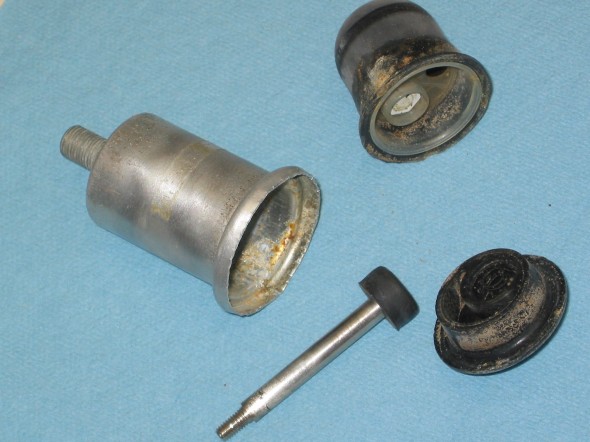
Cigar Lighter
Jaguar incorporated a cigar lighter in the instrument panel assembly. I purchased a new cigar lighter from SNG Barratt and will use this as an alternative power supply for a 12-volt accessory plug. The lighter has two electrical terminal connections. One, to ground connected to a post on the back of the panel, and the second, to the fuse panel. The wire on the second terminal connects through a 4-way snap connector with a wire for the radio and for a supplementary USB port.
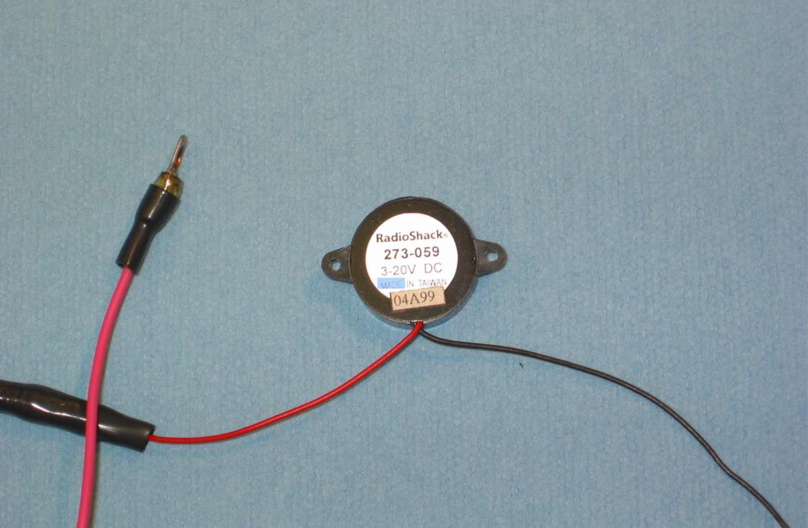
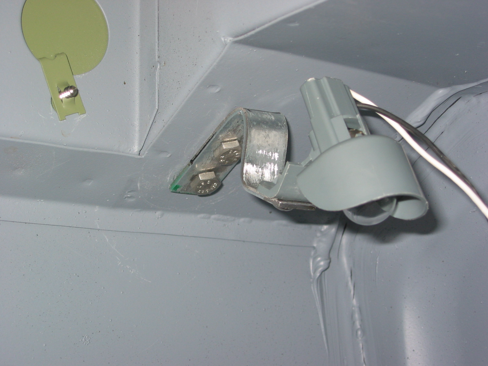
Chime
All vehicles today have chimes or alarms to alert the driver that the lights have been left on upon exiting a car. I thought it a good idea to incorporate this feature in the wiring schematic for the MK2. I used a very inexpensive chime available from Radio Shack, part # 273-071B. The chime is wired to Terminal #3 of the light switch and to the driver’s door (LH) switch. It is located on the back side of the instrument panel assembly.
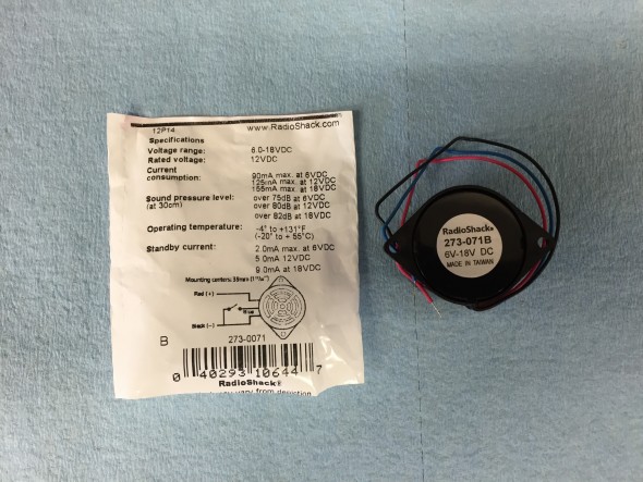
Radio Shack Chime for Headlight Warning
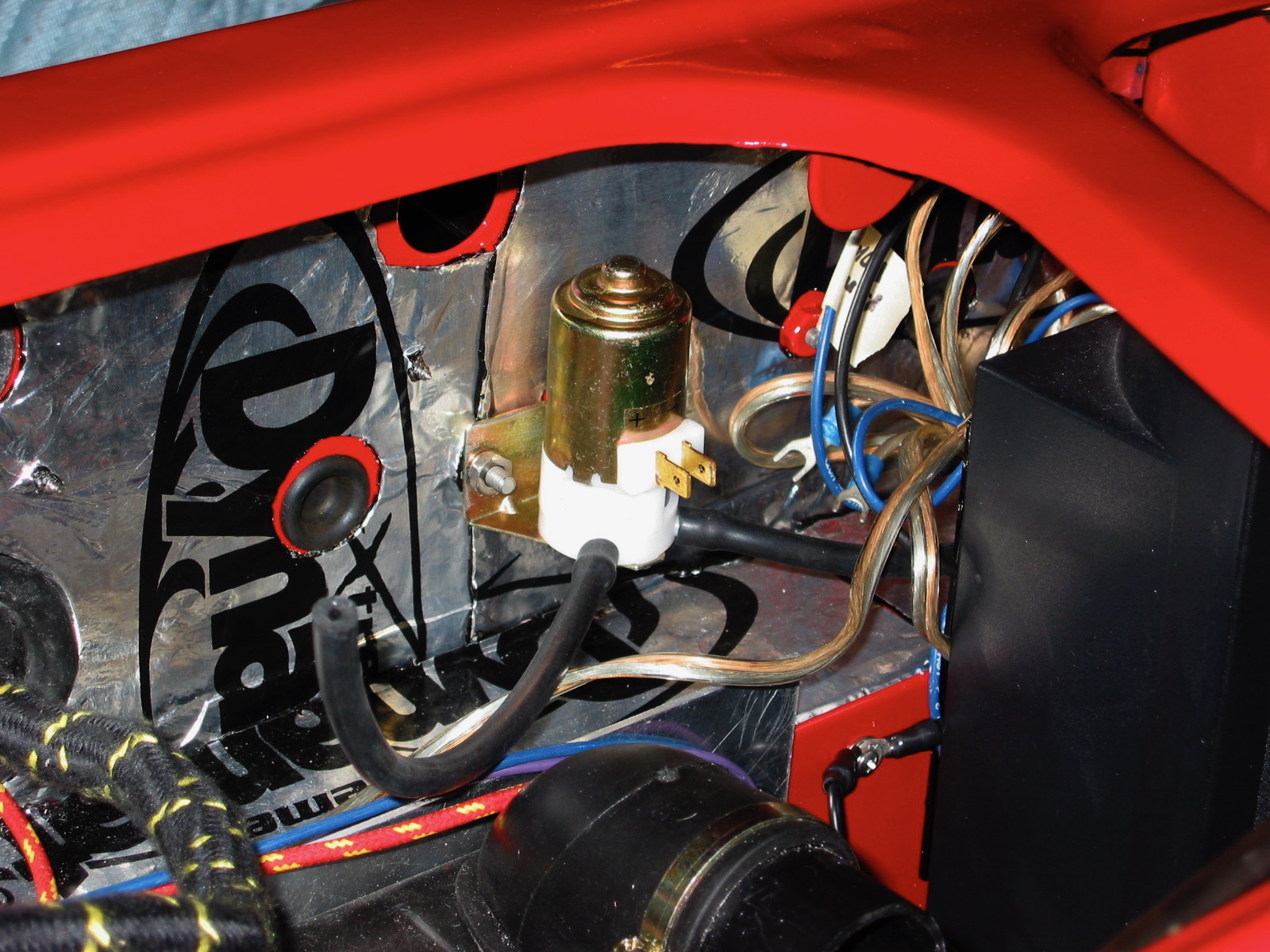
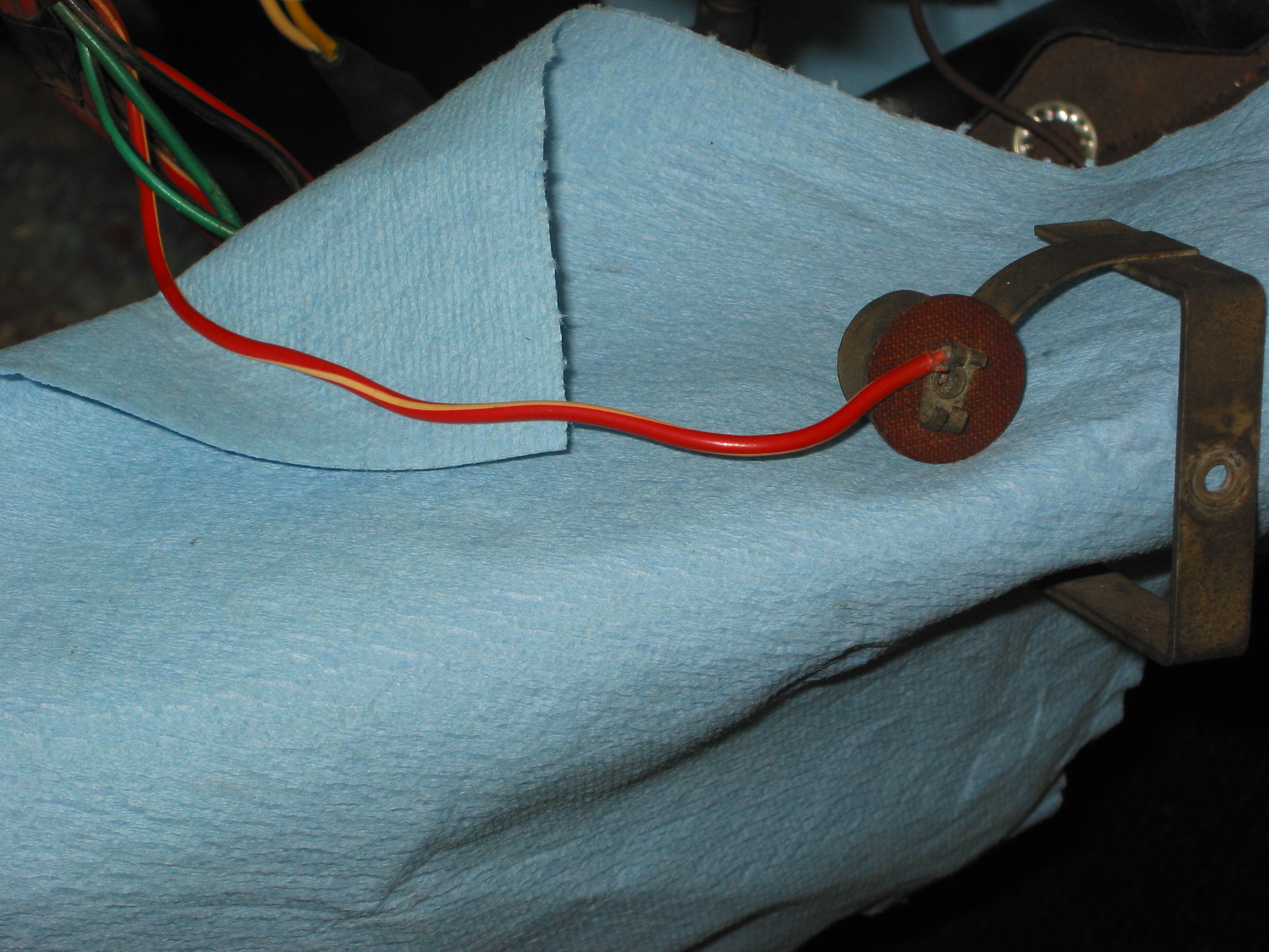
Voltage Regulator/Stabilizer
Although new reproductions of the original Lucas voltage regulator for the instrument panel gauges referenced earlier are available, a better alternative is to use a modern electronic unit for greater reliability. It is available from CoolCat Express Corp: http://tinyurl.com/k9zayo2
These are the instructions for the installation of the voltage regulator:
SSIVR Installation Instructions
This little device receives fluctuating DC current from the battery and outputs a steady 10 volts to enhance the accuracy of the gauge readings.
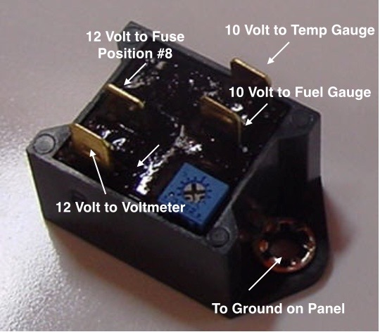
Voltage Stabilizer Wiring
zz