Donald Healey and His Cars
Reprinted from motoring@ridedrive.co.uk – Photos and commentary on the BJ7 added by LH Rose.
Donald Mitchell Healey, son of a Cornish shopkeeper, was born in Perranporth, Cornwall, in 1898. From an early age he displayed a great deal of potential and understanding for mechanical objects and upon leaving school he served an apprenticeship at Sopwith, the aircraft manufacturer where he learned his trade in using machine tools.
After the outbreak of the First World War Healey served in the Royal Flying Corps as a pilot until 1916, when he was injured following an air crash, after which he was discharged as an invalid. Healey returned to his home in Cornwall where he took up a correspondence course in automotive engineering. Sponsored by his father he opened a garage in his home town where he repaired and service cars, and ran a local taxi service. The business prospered until one day, in 1922, he had sufficient funds to buy a competition car and began dabbling in motor sport, including the Lands End to John O’Groats rally. Having entered into competition driving, Healey started to rub shoulders with some accomplished names, such as the Riley Brothers and Cecil Kimber, the man that was involved with the foundation of MG.
Over a period of time Healey began to meet with some success and in 1929 he entered, for the first time, the Monte Carlo Rally in a Triumph Super Seven family saloon car, but was disqualified for being late to the finish. The following year he again entered the race, but this time came seventh overall. By now Healey was starting to get noticed for his driving ability and was approached by a man called Noel Macklin, who asked him to drive an Invicta in the Monte Carlo Rally to give the marque some public exposure. The partnership was successful and in 1930, despite the car only braking on three wheels, Donald Healey came home in first place. During this period, Healey met and befriended Ian Fleming, who later went on to create the James Bond stories, and Fleming actually rode along with Healey as his navigator in an event on the Alpine Trial. Healey again found some success in the Alpine rally, but this time in a Riley Brooklands, a car that he had borrowed from the Riley brothers, afterwards working for a while with Riley preparing their competition cars.
In the years between the two World Wars, the importance for a motor manufacturer to have their car succeed in a major competition was of paramount importance and would make a very large difference in the success rate in selling cars to the motoring public. The Triumph Motor Company were looking for someone with sound technical knowledge and driving ability to fill a position as Technical Manager their plant in Warwickshire. Having already sold his garage business in Cornwall, Healey accepted the position willingly and competed in many rallies driving for Triumph, with whom he enjoyed much success. However, Healey had always wanted to design his own racing car to take on the fierce competition put up by teams such as Alfa Romeo with their Monza 2.3 litre supercharged eight-cylinder car. What Triumph and Healey did was to get hold of a Monza engine, strip it down and then set about copying it. The engine they produced was almost identical and was fitted in the 1934 Triumph Dolomite, a two-seater model with some very impressive chrome exhausts that ran along the outside of the body.
In 1934 the car was entered in the Monte Carlo Rally to prove the design and its robustness. However, Healey’s race was prematurely ended when he was involved in a collision with a train on a railway crossing – a collision that totally wrecked the car but did not injure the occupants. Priced higher than the 3-litre Bentley, only three Dolomites were ever built. Healey remained with Triumph until the outbreak of War in 1939 when the company went into liquidation.
During the Second World War, Healey was a part-time officer in the Air Training Corps, and also worked for Humber, a company making military vehicles for the British Army. In 1945 he wrote an article entitled, “The Enthusiasts Car, “ in which he outlined a dream he had to build a high performance car of his own. In the piece he spoke of many technical matters, such as power-to-weight ratios, engine design and aerodynamics, further motivating him to realise his ambition. When the war finished, Healey and his colleagues from Humber, worked at bringing Healey’s dream car to reality. In his autobiography, he says of the pre-war BMW 328 as being, “The best small sports car of all time,” and it was cars such as these that inspired and drove his ambition. He wanted the BMW engine, but in those early post-war years materials and supplies were difficult to obtain, putting the engine out of his grasp. However, by calling in favours and using the contacts he had built up over his racing years, he spoke to Victor Riley, who agreed to supply Healey with a new and advanced 2.4-litre four-cylinder 100bhp engine, together with gearboxes and axles, that was developed from the engine used to power a competition car driven with some success by Raymond Mays.
Healey’s first car had a body and chassis of his own design, with most mechanical parts coming from Riley, but others being supplied by the Alvis and Nash companies. Persevering against a shortage of materials he produced a chassis with an unusual and advanced suspension unit, incorporating trailing links, upon which he mounted a sports body panelled by Westland Engineering of Hereford. Alongside this car he produced another, a closed body design, that was finished a firm of shop fitters from Reading in Berkshire called Elliots. In January 1946 the new car was shown to an enthusiastic press and many orders were taken, financing the acquisition of some business premises in Warwick, the heart of motor manufacture in England, to become The Donald Healey Motor Corporation.
Healey used mechanical parts, mostly coming from Riley, with others being supplied by companies such as Alvis and Nash. His mechanics were people he managed to poach from other car manufacturers and between 1946 and 1950 the company produced the Westland Roadster and the Elliot Saloon.
Healey Westland
Healey Elliot
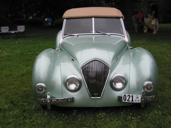
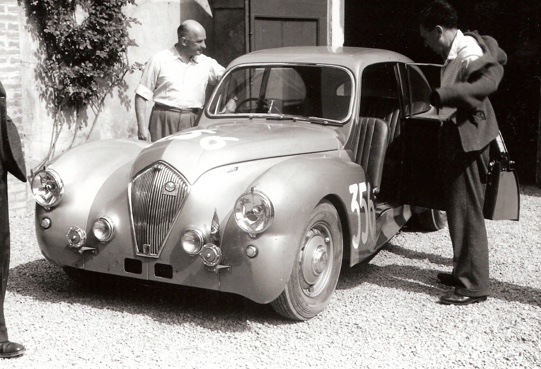
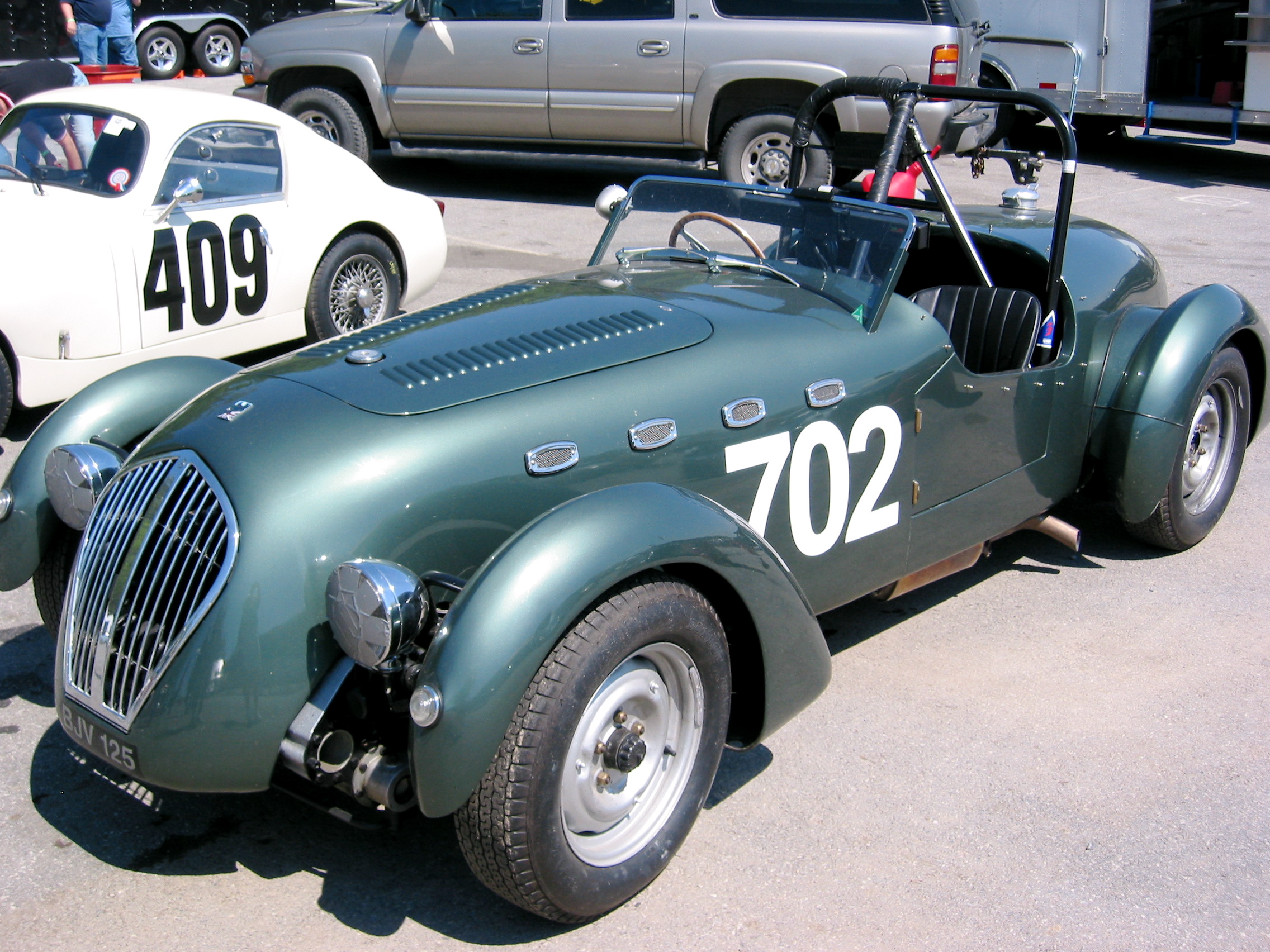
These cars were not cheap and were competing with the likes of Armstrong Siddeley and Aston Martin, but in 1949 The Donald Healey Motor Corporation produced something quite spectacular, the Healey Silverstone. This sports car sold for less than £1,000 (before tax), and soon became a popular choice among the sporting drivers of the day due to their superb handling qualities. This was a thoroughbred sports car powered by the twin camshaft version of the Riley 2.4-litre engine, in which a driver by the name of Tommy Wisdom broke the World Hour Speed record at Monthléry in 1952.

Healey Silverstone
After that the name Healey became known for quality sporting saloons and roadsters, the chassis’ of which would often be supplied to customers for coachwork, as was common with Bentley and Rolls-Royce, for coachwork by Abbot of Farnham, Tickford, and Duncan Industries of North Walsham amongst others.
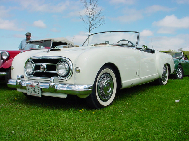
The business was going well, but Donald Healey had set his sights on volume manufacture and in December 1949 he went on a sales mission across the Atlantic to the USA to promote his cars and hopefully return with orders. Whilst en route to the States he had a chance meeting aboard the Queen Mary with Nash, the president of the Nash Kelvinator corporation. This resulted in a commission, funded by Nash, to develop a car for the US market that would be based on Healey’s chassis and with the 3.8-litre Nash engine paving the way for the Healey-Nash.

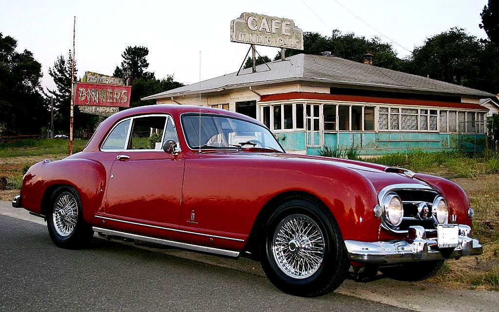
Nash Healey

Nash Healey
This was the turning point for The Donald Healey Motor Corporation, an event which supplied sufficient revenue for him to set about developing a new model, a car that he would make him a legend in car manufacture and design.
Healey made many visits to the USA and identified a market opportunity for a sports car that would fit between the Jaguar XK series and the MG. Upon his return he set about developing a prototype sports model, secretly building it at his home so as to conceal it from Nash, who although were working with him at the time on the Healey-Nash project, Healey was planning to compete against him and Morris, the company that were supplying the Riley engines, with the new project. The new car, he decided, would have a different engine and after discussions with Leonard Lord, head of The British Motor Corporation (BMC), Lord agreed to supply Austin A90 power units.
The four-cylinder 2.6 litre Austin unit was ideal, but Healey disliked the gearbox ratios. To solve this perceived problem he blanked off the very low first gear, making it into a 3-speed gearbox and then fitted an overdrive unit that operated on second and third, which had the effect of turning three gears into five. The result of Healey’s efforts was the Healey 100 (the 100 standing for both 100mph and 100 horsepower), a stunning two-seat sports car that he introduced at the 1952 London Motor Show at Earls Court.
Before the show opened, Leonard Lord had a look at the car and was smitten with it. The Austin Motor Company desperately needed a sports car to compete with MG, the new Triumph TR2 and the Jaguar XK 120, and this car appeared to be have the potential to do just that. Legend suggests that prior to the show, Leonard Lord had set a task for three manufactures to each produce a sports model for this exhibition where he would make a judgment as to which manufacturer he would award a production contract to. The two other ‘competitors’ apart from Donald Healey were Jensen and Fraser-Nash, but the Jensen car was not finished and so was not shown.
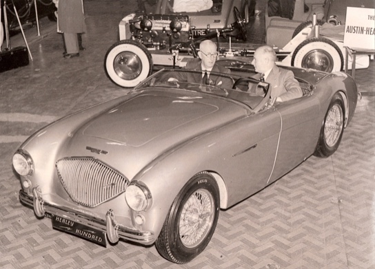
The Healey Hundred – DMH and Leonard Lord
When the show opened the Healey 100 took the crowd by storm and won rave reviews from the press. Leonard Lord decided there and then that this was the car he wanted and to be produced under the Austin name, no doubt inspired by the reception the car received. All the ingredients were there. Healey wanted the production capacity of an established car manufacturer to produce his design and Lord wanted to produce the car because he believed it would sell in large numbers. What resulted was a partnership between BMC and The Donald Healey Motor Corporation to form the name of Austin-Healey, and was the start of a relationship that would last for sixteen years. However, the construction of the car did not just involve Austin and Donald Healey.

The Austin-Healey 100
The first 20 pre-production Healey 100’s were assembled at Healey’s small plant in Warwickshire and then, in 1953, production assembly moved to the Austin factory at Longbridge. Whilst the engine and transmission was manufactured by Austin, the chassis was constructed by a company called John Thompson Motor Pressings and the bodies supplied, assembled and trimmed by the Jensen Motor Company. Jensen had the capacity to produce these in the numbers required, whereas Austin could not, but could at least assemble the car at its Longbridge plant. Also in that year The Austin Healey 100 won the Grand Premium Award at Miami’s World Fair in the United States and was voted the International Motor Show Car of 1953 at New York. As a publicity stunt a standard production car is taken to Utah Salt Flats and recorded an average 103.94 mph over a 5,000km endurance run. By the summer of 1954 the production of the Healey 100 at the Longbridge production plant was producing in excess of 100 cars per week for the first time, in fact over the first three years since its launch, 14,600 of them were made, 3.5% only of which remained in the UK.
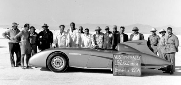
Bonneville Streamliner
Donald Healey couldn’t seem to let go of his racing past and motor sport was still very much in his blood. In 1956, to further publicise the car, Donald Healey achieved almost 193 mph over a flying kilometre in a 224bhp supercharged and streamlined version of his car, while Carroll Shelby, who would later build and produce the AC Cobra, went on to break sixteen U.S. and international speed records with it, where he averaged approximately 160 mph.
These record-breaking achievements and motor racing successes resulted in further development of the car, which produced the famous Austin Healey 100S, the `S’ standing for ‘Sebring.’
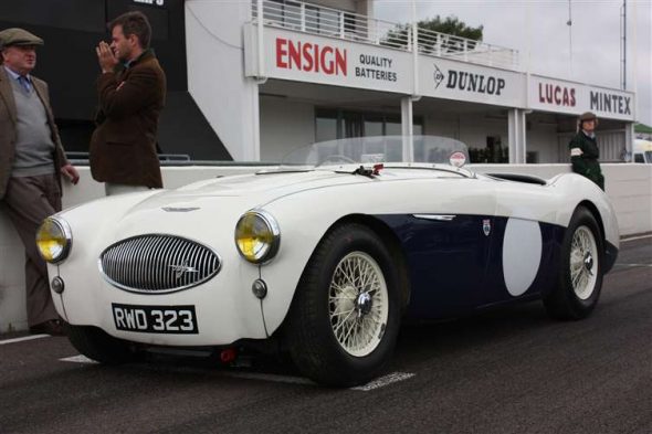
100S
Such was Healey’s confidence in the strength of his car the Austin-Healey 100S was entered in many competitions, including the prestigious Le Mans 24-hour endurance race, where it enjoyed substantial success. In fact, at the 1955 Le Mans meeting, it was a Healey 100 ‘Sebring’ model, raced by Stirling Moss and Lance Macklin, that was involved in the terrible accident when a Mercedes catapulted over the rear of the Healey and flew into the crowd killing 50 spectators and injuring many more. The 100 Sebring was constructed from Aluminium body panels and had a heavily modified engine. Only 55 of them were ever built.
The Austin-Healey 100 went through several technical development changes until in August 1956 the four-cylinder 2.4 litre Austin engine was discontinued to be replaced by a six-cylinder unit of the same cubic capacity from the Austin Westminster. Donald Healey thought he had identified a market for a sports car that could carry four people instead of just two and so the updated car was given a new 2+2 body. The name of this model was the Austin-Healey 100/6, but it proved not to be so popular as the previous two-seater model on account of its comparatively inadequate power output of only 104bhp from what should have been an awesome engine. The problem with it was that the cylinder head had an integral two-port inlet manifold, which meant it was not able to get an adequate amount of fuel and air into the combustion chambers. Being made of cast-iron the engine was also very heavy, the combination of which made the performance of this new car worse then the old one it replaced.

AH 100-6
Due to the dimensions of the new six-cylinder unit, extra space had to be found in the engine compartment and a bulge with an air scoop were put into the bonnet panel to provide sufficient clearance at the top and front of the engine. The familiar shield-shaped radiator grille was now replaced by a new oval one and which was reminiscent of the 100S, having wavy horizontal bars, a feature on all the Austin model of that period. Other alterations included modifications to the chassis, which saw the removal of the front cross-bracing so that the radiator, this being taken from a Healey saloon, could be fitted beneath the front of the bonnet with only the top header being exposed when the panel was raised. Additional engine mountings were welded in behind the original four-cylinder mounts and the passenger side bulkhead ceiling was lowered to allow space for the carburettors. The transmission tunnel was also enlarged at the front to make space for the engine, to the extent that there was 4 inches less width to the foot wells, making them very narrow indeed. In addition to the new six-cylinder engine, the length of the chassis was increased by two inches between the axles to allow room for the new rear seats. To accommodate these the rear panel behind the cockpit was made smaller to make more room in the car, but with a loss of a large proportion of the boot space. The twin 6-volt batteries, that had been positioned within the engine compartment on the 100/4 were replaced by a single 12-volt unit, now housed in the boot, with the spare wheel being stored on the boot floor.
Unfortunately, the rear seats did not work well with the car, on account of there being very limited leg-room, and those that did manage to squeeze into the back found that their heads were placed directly in the slip stream of air coming off the top and around the sides of the windscreen making their travelling experience most uncomfortable. Since there was very little room in the downsized boot for luggage, this now having to be carried on the newly fitted rear seats, the car was only really ever used as a two-seater anyway. It was in the form of this Four-Seater Sports Tourer that the 100/6 made its debut at the beginning of 1957 to a very lukewarm reception. The press were unusually kind to the car, trying to look at the positive aspects of the new design, suggesting it to be more practical and smoother than the model it replaced, rather than slating it as a bad idea.
Late in 1957, so as to counter customer complaints concerning the meagre performance of the 100/6 engine, the cylinder head was revised and improved, but it had taken a year to do it. The new head, however, made a big difference, and now had a separate six-port manifold, which increased the power output to 117bhp and with a very useful increase in torque. After the introduction of the 100/6, the older four-cylinder cars were dubbed as the 100/4, an unofficial title and one that was never used by the factory. This was also the year in which production of Austin Healey cars moved from Longbridge to the MG factory in Abingdon, Oxfordshire, where it was built along side the MGA and Riley saloons, and from where the two seater version was re-introduced to run along side the 2+2.
1958 saw the introduction of another Austin-Healey car. The new model was also an open-top sports car, but much smaller in size than its big brother, the 100/6. Having apparently identified a gap in the sports car market, Donald Healey and Leonard Lord set about producing a small ‘budget’ sports car built largely from the components of the Austin A35 saloon.
This resulted in the launch of the Austin-Healey Sprite, or the ‘Frog-Eye’ Sprite, as it became affectionately known on account of the positioning of the headlights above the mouth-shaped grille.
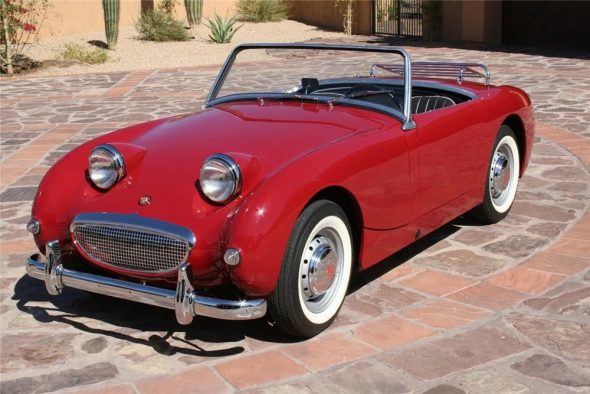
Bugeye Sprite
In 1959 the Austin Healey 3000 was launched, a car that was quickly christened the ‘Big Healey’ by the public and the press alike. The car was a sensation, as not only did it look fantastic, it sounded good and performed very well on the road. The engine was a development of the 100/6 2.6-litre unit and now had a capacity of 2912cc, which produced 124bhp.

AH 3000 MKI BT7
The front brakes were up rated to discs, a relatively new idea at the time, and the body was offered in both a two-seater and as a revised 2+2. The introduction of the 4-seater, which had been modified in its design to give the occupants and their luggage more space, was much more acceptable to the buying public and eventually it was outselling the two-seater version that was being produced at the same time.
In 1961 the Mk11 was launched featuring a triple carburettor set up on the engine, which significantly increased the engine power output to 132bhp, as well as its thirst for fuel!

AH 3000 MK2 Tri-Carb
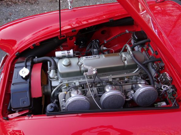
AH 3000 MK2 Tri-Carb
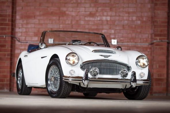
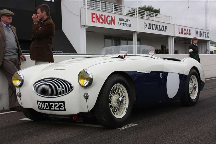
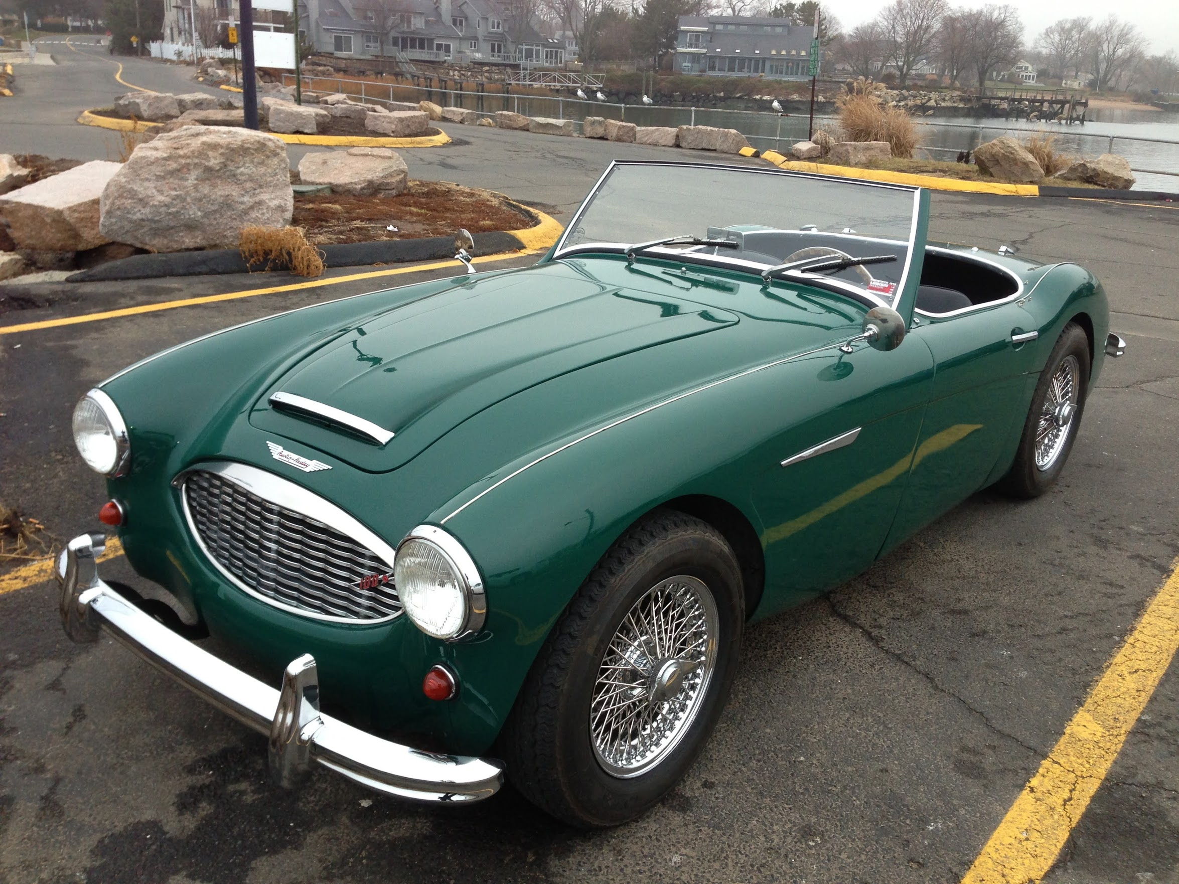
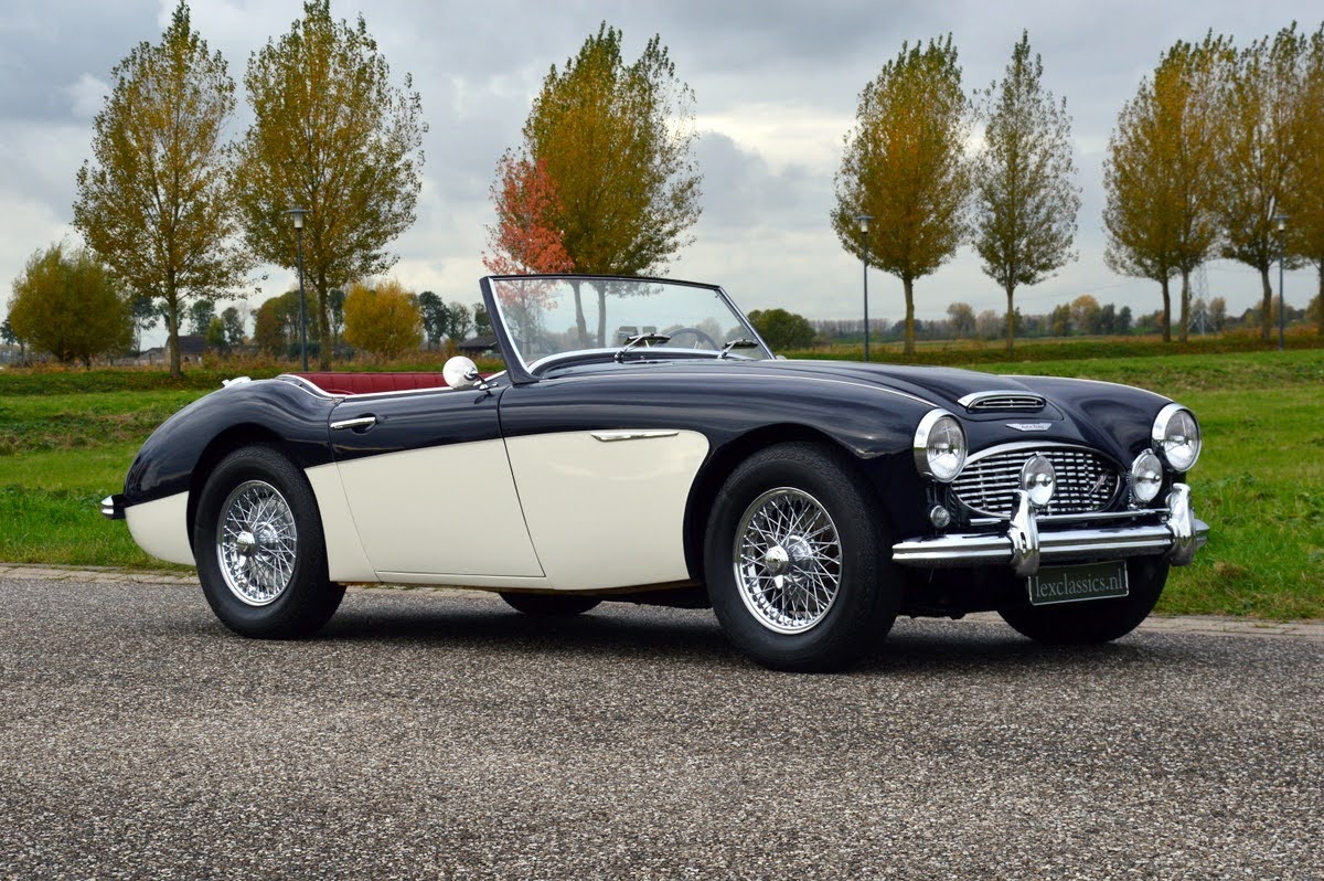
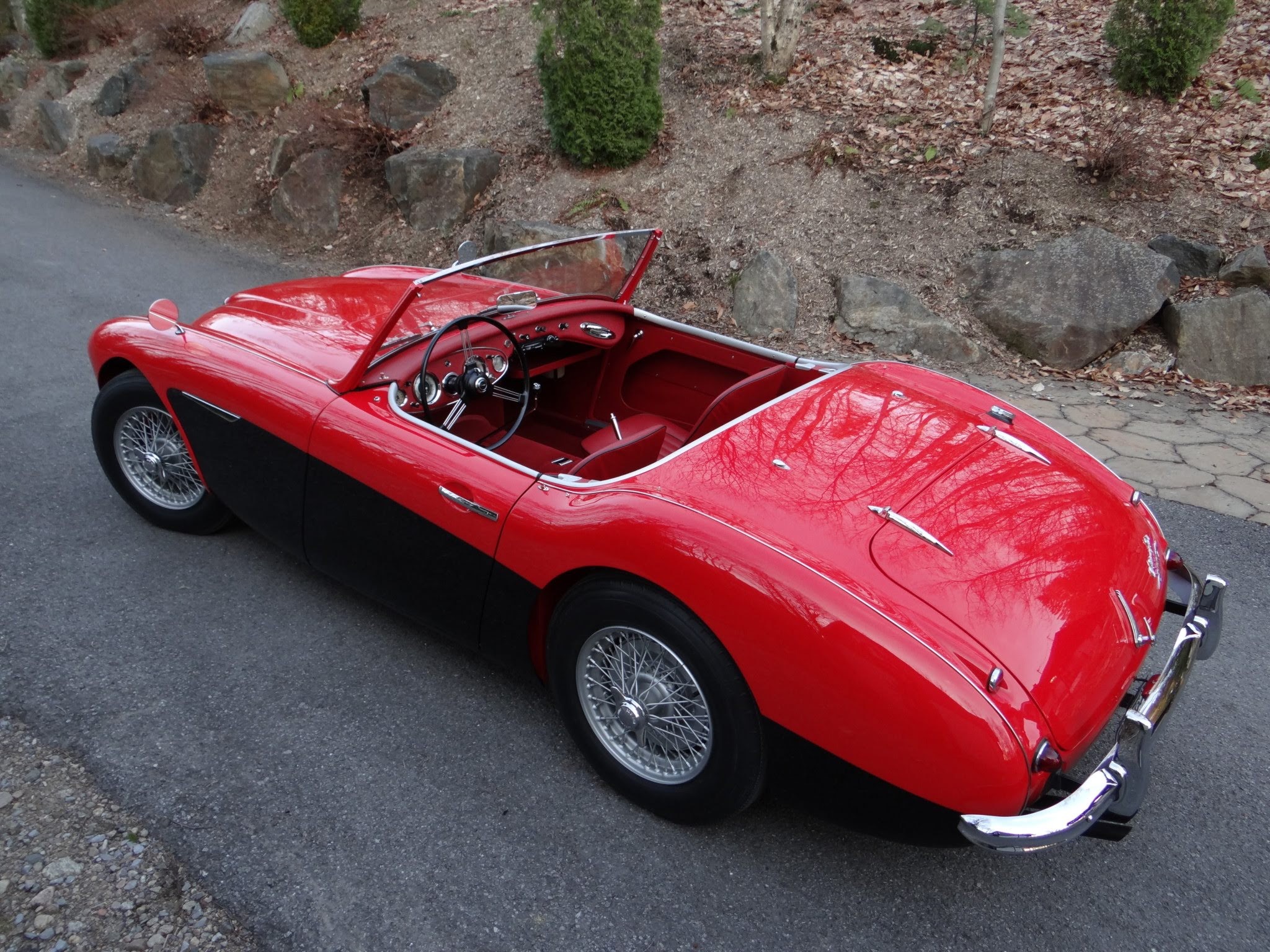
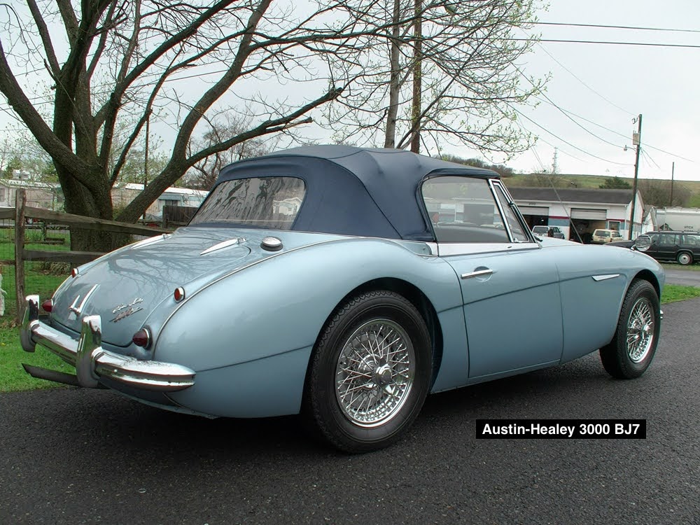
However, in January 1962 the Mk 11 emerged with two large carburettors replacing the triple carburettor design, and for the first time the car received windup side windows. This model became known as the BJ7.

AH 3000 BJ7
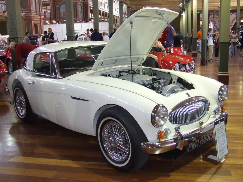
In 1963, in the Austin-Healey 3000 MkIII, the 3-litre engine received a new design in camshaft, coil springs for the valves, bigger twin HD-8 carburettors increasing the power output to 148bhp.
AH 3000 BJ8 One-Light
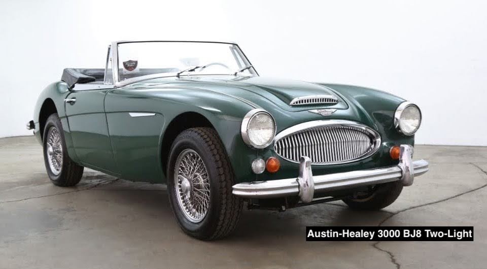
The car received a whole new interior, including a new dash panel layout. Another innovation was that the car was no longer started up by use of a button, but by use of the ignition key. In May 1964 the car was again modified with alterations being made to the chassis to give the rear axle more vertical travel, to improve the ride quality of the car, and the leaf-spring suspension increased to six-leaves. On the outside of the car the auxiliary ‘flasher’ lamps at the front were enlarged in size to match the headlights.

AH 3000 BJ8 Two Light
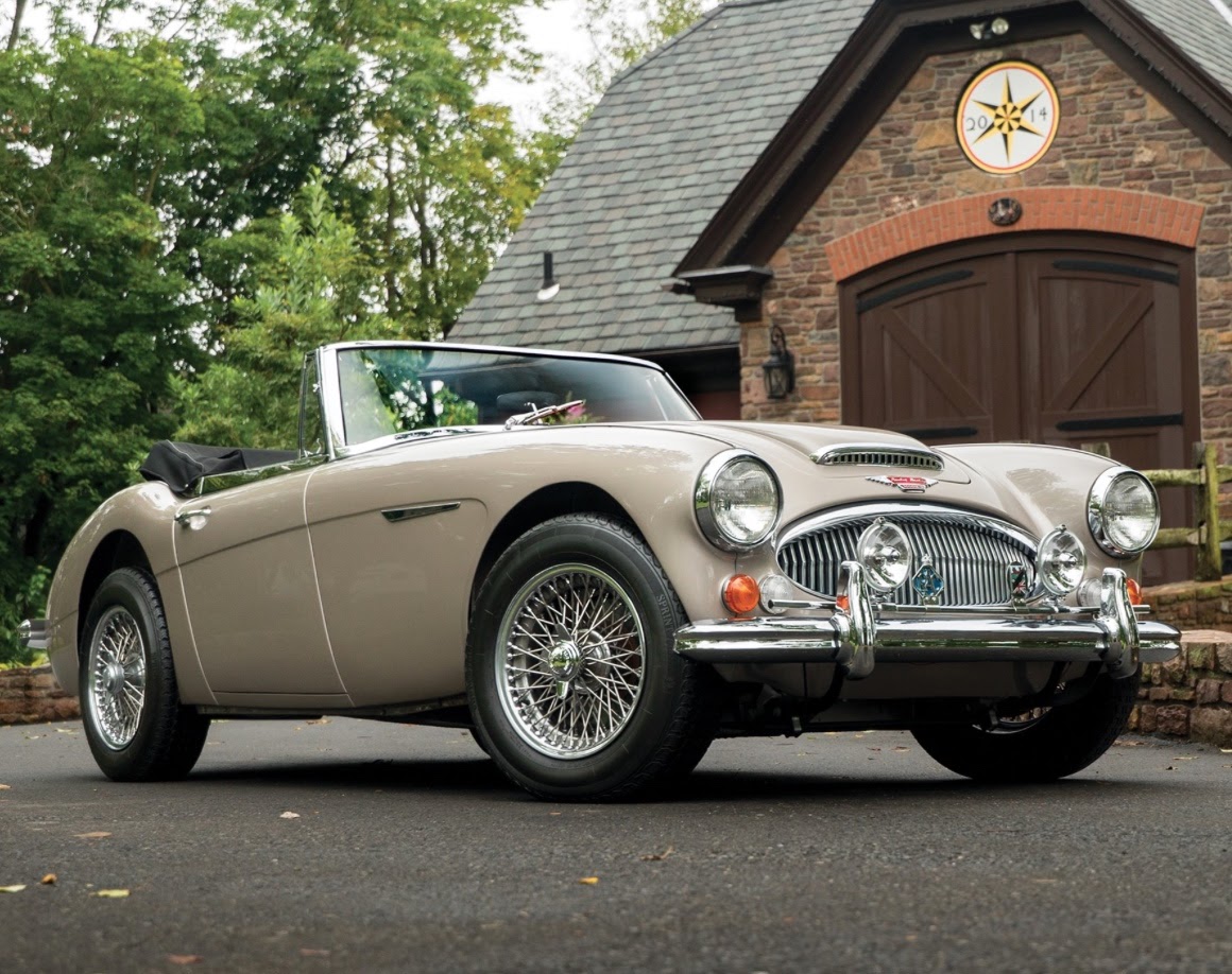
1967 was the last full year in which the Big Healey was built, with 3051 models leaving the factory and with the last examples, manufactured during November and December of that year, being finished in gold paint and black interior – a car that has become known as ‘The Golden Healey.’

Beige Gold metallic BJ8
Due to the total breakdown in relations between Donald Healey and the new owners of BMC, British Leyland Motor Corporation, in March 1968 only one Austin-Healey 3000 was built in right hand drive form after which all production of the car ceased.
This was not the end of Donald Healey’s involvement in car production. In the closing years of the 1960s, the Jensen Motor Company was in deep financial difficulty. The Austin-Healey 3000 had been discontinued and with no other model to replace it the contract they had with Donald Healey, together British Leyland Motor Corporation, had come to an end. Compounded with that there were build quality problems with the Interceptor, a factor that was putting off many potential buyers for the car. To get away from this heavy financial burden, the Norcross Group sold the company to merchant bankers, William Brandt. Sons & Company limited, and through careful management the production of the Interceptor was increased to try and improve sales – and then decreased later to improve build quality. However all of this was futile and the Jensen Motor Company looked like it was going nowhere, seemingly destined for collapse. However, having been severely battered by his experience with the new British Leyland Motor Corporation, who had pulled out of the production of Austin-Healey sports cars, Donald Healey once again formed an association with Jensen and went on to build a new sports car together with a San Fransisco businessman, Mr, Kjell Qvale.
Qvale operated a very successful company selling Jaguar, Rolls-Royce and other British cars in the United States. He too was dismayed at the discontinuance of the Austin-Healey 3000 and learning of the role played by Jensen in the construction of the big Healey, he was interested in Donald Healey’s plans to build a new sports car. Before long Qvale became a majority shareholder within the Jensen Motor Company and took control, appointing Donald Healey as Chairman, with Geoff Healey as one of the directors, an event that completely and finally severed all involvement between Donald Healey and British Leyland.
From the newly formed relationship there came a new car with a new brand name, the Jensen-Healey. This was a whole new vehicle that promised much, but turned out to be very disappointing.
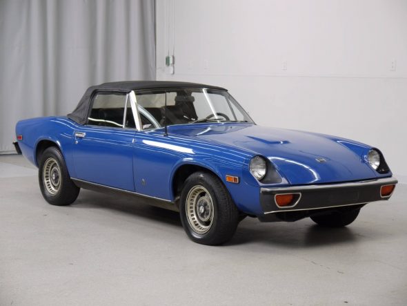
Jensen-Healey
Right from the outset there were problems with the build quality and with engine reliability. First the car had a Vauxhall engine, and then one from BMW was considered, before an untested and under developed Lotus unit was used. This engine seemed a wise choice as not only did it satisfy the new US exhaust emission regulations, but it was designed to be fitted at an angle of 45 degrees, which meant it was not very tall providing the opportunity to use a low profile body. However, Qvale was impatient and insisted upon the engines being delivered early, way before they had been fully developed, and the finished car made its debut at the Geneva Motor Show in March 1972 to the initial approval of the press.
It wasn’t long though before the faults became apparent, something that cost the Jensen Motor Company a considerable amount of money, money they could not afford to spend. In August 1972 the Mk11 version was released. This was a vastly improved car and was shortly improved again in November 1974 with the fitting of the German Getrag five-speed gearbox. However, Donald Healey had become totally disillusioned with the whole Jensen organisation and left the Jensen Board, refusing to allow his name associated with the fixed-head, hatch-back GT version of the Jensen car introduced in July 1975.
With the connection between Jensen and Austin, as well as the relationship between Donald Healey and Austin, being a distant memory, Jensen lurched from one problem to the next, but it was the energy crisis of 1974 that carried Jensen to the brink of total collapse. A plea to the serving Labour Government at the time was rebuffed and in May 1976, Jensen Motors Ltd ceased trading forever.
Following the demise of Jensen, Kjell Qvale purchased the company assets from the Receiver and went on to form another company that specialised in servicing and renovating Jensen cars, a project supplemented by the importation and distribution of Subaru and Hyundai cars.
After the demise of the Austin Healey 3000 in 1968 it transpired that The Donald Healey Motor Corporation had been secretly dabbling with a new model to succeed it – a car that never made it to production. It appears that three of them were built, and although it may have looked familiar from a distance, upon close inspection it really was quite a different animal.
What Donald Healey had done was to take the body from an Austin Healey 3000, cut is in half longwise and weld it back together with a six-inch fillet inserted between the two halves. Rumours have suggested that there had been a fourth car, but so far these are found to be untrue. Under the bonnet was a Rolls Royce engine, complete with Rolls Royce markings, an engine the same as that fitted to the Austin Princess R.

Healey 4000 Prototype
It makes sense for this to have been the choice of the factory because of the association between Healey and Austin at that time, and for its availability. The power unit was made from alloy, making it somewhat lighter than the cast iron example of the Healey 3000. This would mean that the weight distribution would be better, and with the widened track, would undoubtedly have better handling properties. The gearbox appears to have been from Jaguar, as fitted to the E-Type, and the rear axle was either a normal Healey 3000 item, or the one from the MGC. Two of the three cars were fitted with automatic gearboxes, the third being a manual with an overdrive unit fitted, but acting only on fourth gear.
This story of the secret building of these three cars by the old Donald Healey company is indeed a magical one and of a kind that fairytales and dreams are usually made of, except that this one is a real one.
No doubt, if the car ever had been taken into production, this Rolls Royce powered model would have gone down very well, especially in the USA.
The ‘Big’ Healey is regarded as perhaps the epitome of British sports car manufacture and is undoubtedly one of the most sought after classic cars of today – an observation supported by the huge sums of money they fetch when they occasionally appear at auction. As long as there are those that are enthusiastic enough to look after the remaining cars they will always continue to invite awe and admiration as one of the greatest sports cars of the twentieth century.
As for Donald Healey, on 15th January 1988, in his native village of Perranporth in Cornwall, he passed away a few months before his 90th birthday. A legend to motoring enthusiasts the world over his cortege fittingly included many representatives of the cars that bear his name. 


