Chapter 12 – Disassembly

February 2, 2003

Front Suspension Components. 

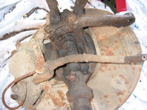
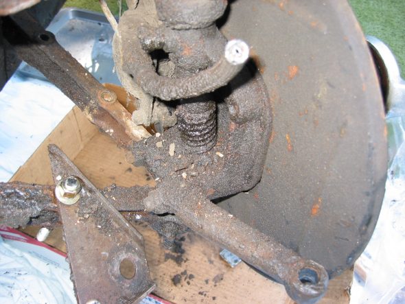
Removed the steering arm by loosening two 11/16” nuts with tab washer connector flattened. Note that the steering arm angles toward the dustshield – not the motor.

Stub Axle Carrier, King Pin, Caliper, Dust Shield

Stub Axle Carrier, King pin, Dust Shield

Brake Caliper – Removed by first unscrewing the brake pipe union. Remove two nuts securing the brake hose support bracket. Remove bracket. Unscrew two caliper retaining bolts.

Removed two rubber bushings from the upper trunnion.

Swivel Pin – Removed split pin at the swivel pin nut and tap swivel pin out with hammer.

Loosen cotter on the swivel pin and retract. Loosen two large nuts (bushings) on “A” arms and remove. Pull out pin and remove “A” arms.

Grease Cup – Pulled out grease cup from hub – fabricated tool with long manifold nut and 5/16” x 3” bolt and the slide hammer.

Straighten and retract split pin on castle nut through the hole in the splines on the hub. Not easy to do!!

Remove castle nut. Brake rotor and hub then lift off of the dust shield and spindle.

From the swivel axle spindle removed the dust cover spring and upper and lower dust covers. Separated the rotor from the hub. 4 bolts  – 2 long ones hold the brake caliper and bracket. 2 short bolts hold the plate to the swivel axle.

Removed rubber “U” seal from around the dust shield opening for the swivel axle.

March 12, 2003

Steering Idler and Steering Box

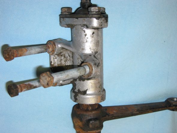
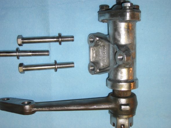
The steering idler and steering box are next for cleanup. I will have these  rebuilt by someone who knows what they are doing. Probably Bruce Phillips at Healey Surgeons.

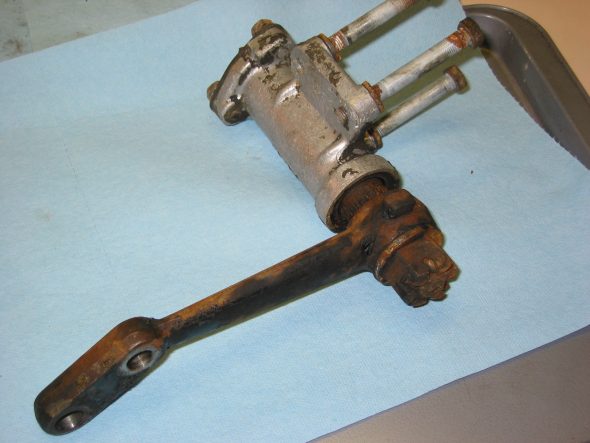
Steering Idler 2

Steering Idler Clean

Steering idler 3

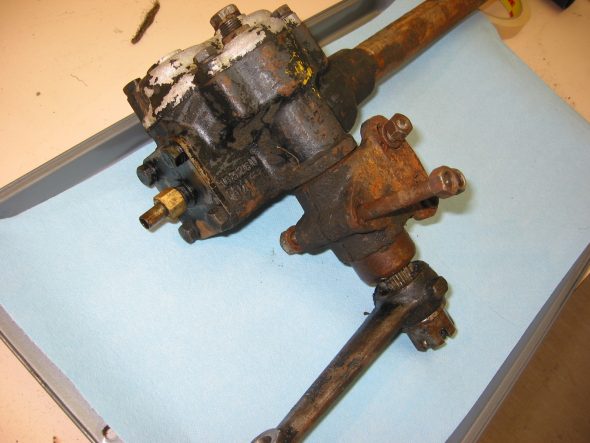
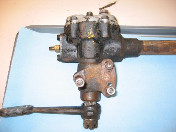
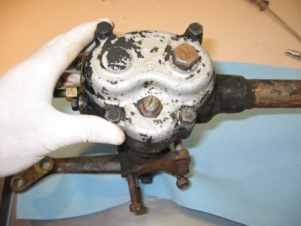
Steering Box 6

Steering Box 5

Steering Box 7

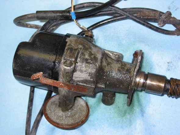
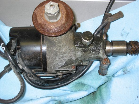
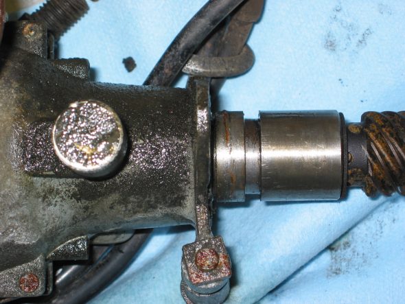
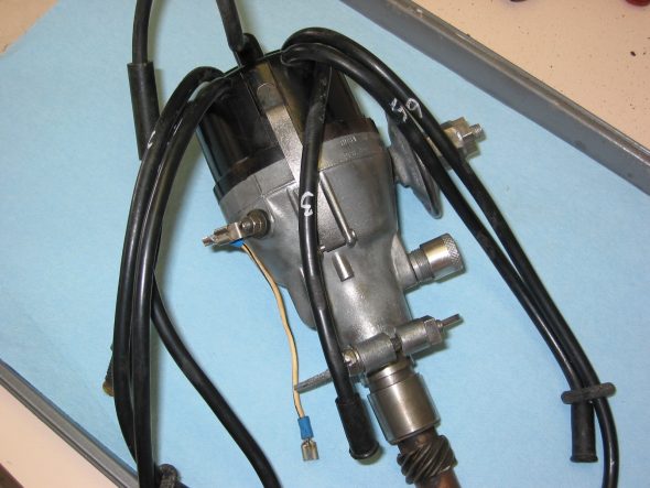
Distributor

The distributor was also in good shape and easy to clean. We may still switch to an electronic unit, but cleaned up the Lucas just in case.

Distributor 7

Distributor 8

Distributor 9

Distributor Clean

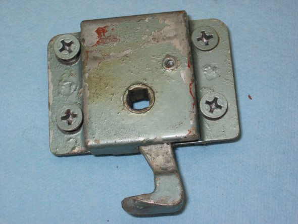
Boot Latch and Lock Assembly

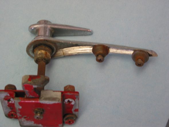
The boot latch and lock assembly was in reasonable shape but the chrome will have to be replaced as it is cracked rather badly.

Boot Lock

Boot Handle & Lock

Master and Slave Cylinders

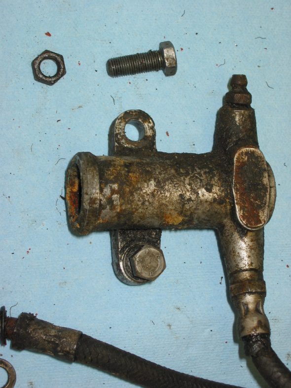
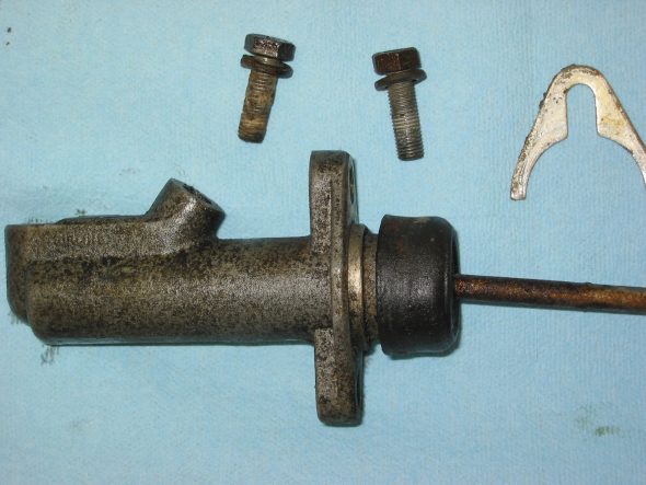
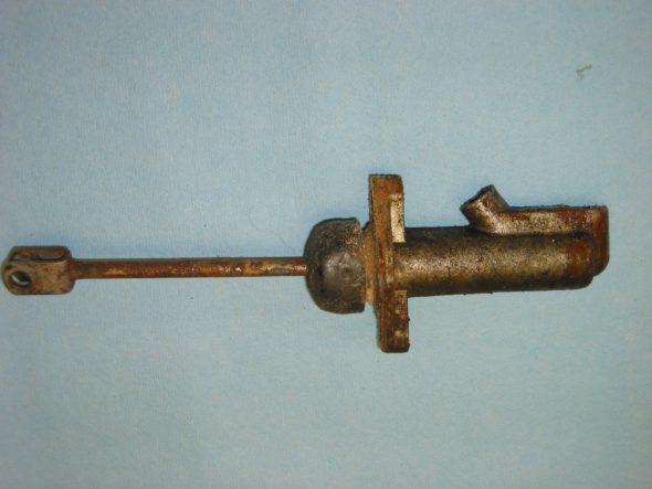
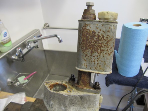
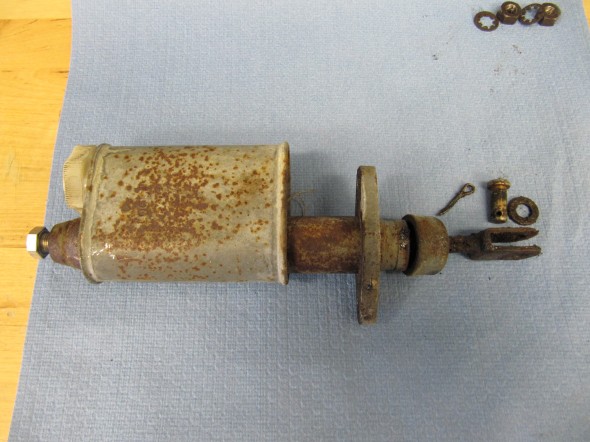
The clutch master and slave cylinder will both be replaced with new items.

Clutch Slave Cylinder

Clutch Master Cylinder with aluminum spacers

Master Cylinder Brake

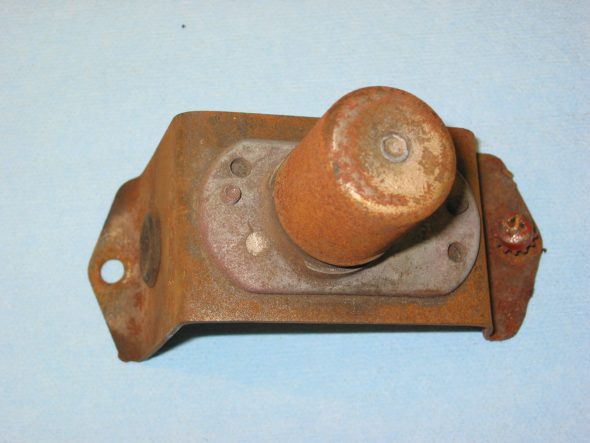
Headlamp Dip Switch

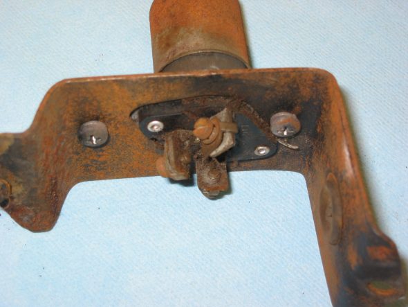
 The switch didn’t look too good, but it worked fine and would clean up.

Dipper Switch

Dipper switch 4

Brake and Clutch Pedals 

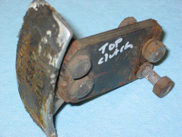
Curiously, one of the previous owners of the car added spacers on the brake and clutch pedals to minimize reach. We won’t use the spacers.

Clutch Pedal 1

Clutch Pedal 2

Clutch Pedal 3

Brake Pedal 4

Brake Pedal 5

Windscreen Wiper Motor

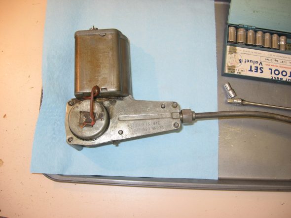
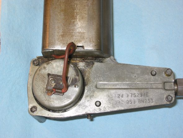
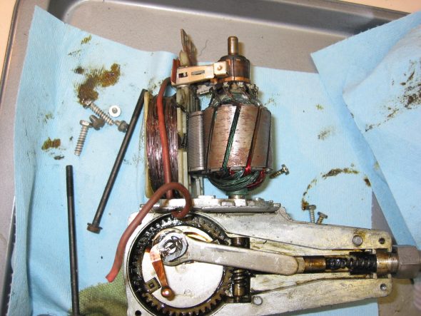
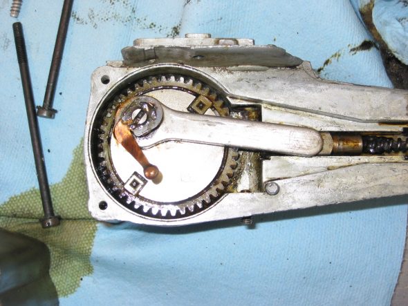
The next item to tackle was the windscreen wiper motor. It was disassembled, cleaned, lubricated, and painted. I tested the motor and it seemed to work fine.

Wiper Motor 3

Wiper Motor 4

Wiper Motor 6

Wiper Motor 7


Brake Servo & Hydraulics

Brake Servo & Hydraulics

Brake Servo and Hydraulics Schematics
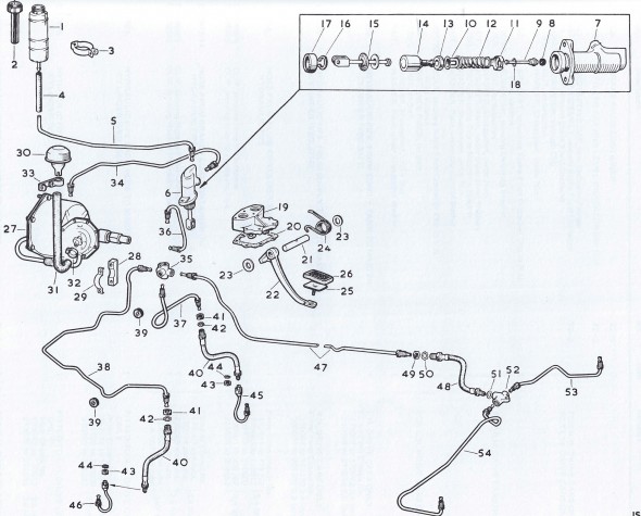
Brake Servo & Piping
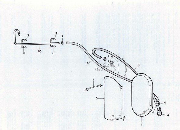
Reservac, Stoneguard & Piping

Brake Servo

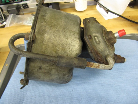
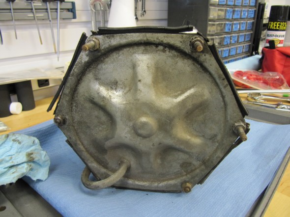
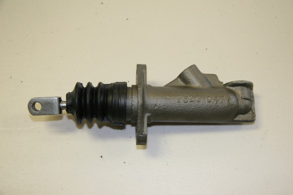
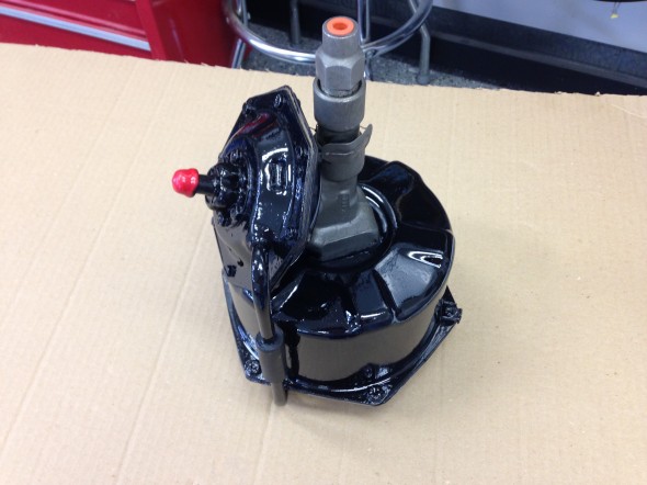
The MK2 uses a Lockheed 6 7/8″ brake servo. I decided to have my servo rebuilt rather than purchasing a new unit. Rich Chrysler, an Austin Healey friend always swore by John Stuart Power Brake  in Ontario so I decided to use them to refurbish the servo and to sleeve (with Stainless Steel) the Girling 875 master cylinder.
Brake Servo
Brake Servo
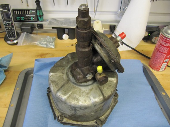
Brake Servo
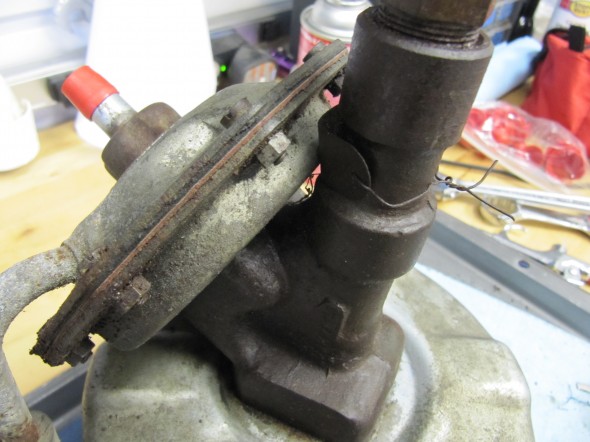
Brake Servo

Brake Servo

Brake Servo

Brake Servo

Brake Servo

Rebuilding the servo and master was not an inexpensive proposition! But both components have been bench tested and are now ready for installation.
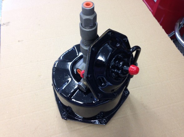
Brake Servo Painted for Installation
Brake Servo Painted for Installation

Rebuilt Master
Rebuilt Master

Brake Servo Painted for Installation
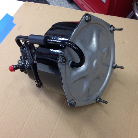
Brake Servo Painted for Installation

Brake Servo Painted

Brake Servo Painted

Stoneguard and Reservac Tank

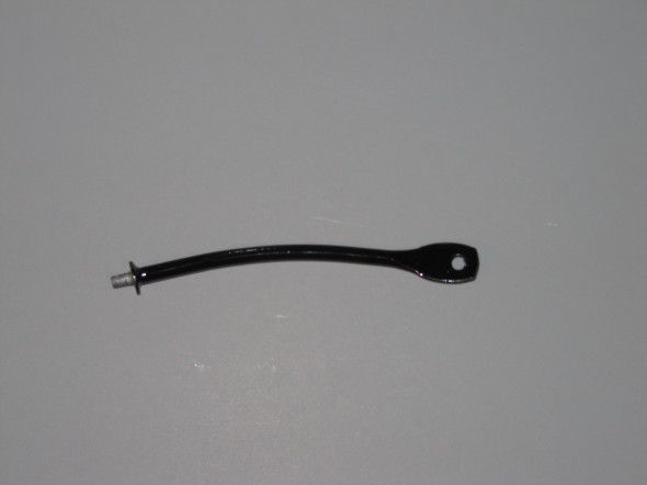
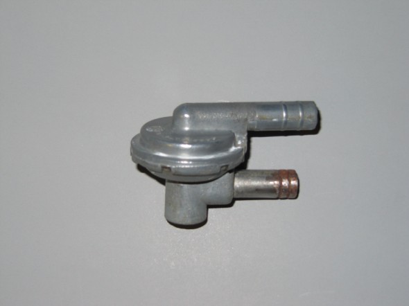
I decided to go with a brand new Stoneguard and Reservac Tank purchased from SNG Barrett. I may change the color later but I decided to paint these two components with gloss black POR 15. The tank was fastened to the stoneguard with four hex head #10 -32 x 5/8″ bolts, shakeproof washers, and hex nuts. The support rod attaches to the stone guard/tank assembly with a #10 hex nut and washer. The original check valve is shown below but I will replace it with a new device.
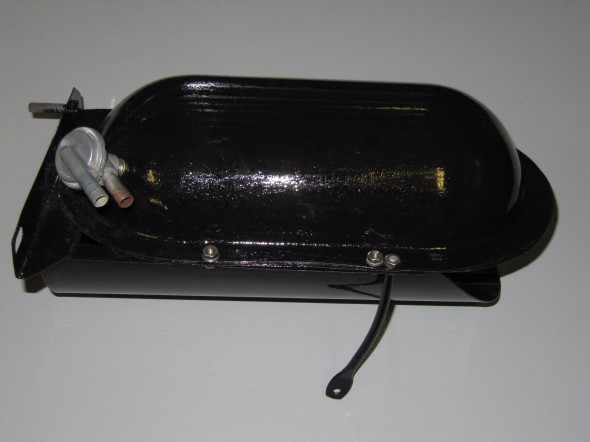
Reservac Tank Assembly
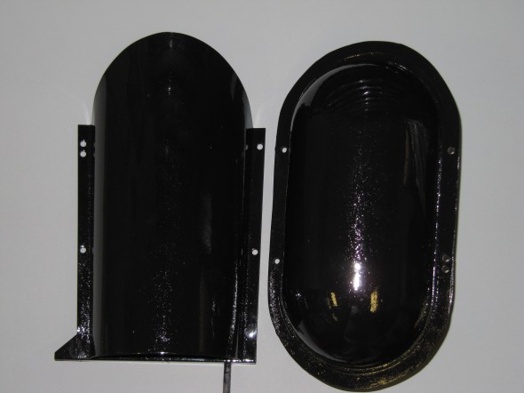
Reservac Tank Assembly

Stoneguard & Reservac Tank
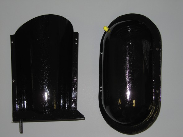
Stoneguard & Reservac Tank
Stoneguard & Reservac Tank

Stoneguard & Reservac Tank

Rod for Reservac Tank
Rod for Reservac Tank

Reservac Check Valve

Reservac Check Valve


Servo Mounting

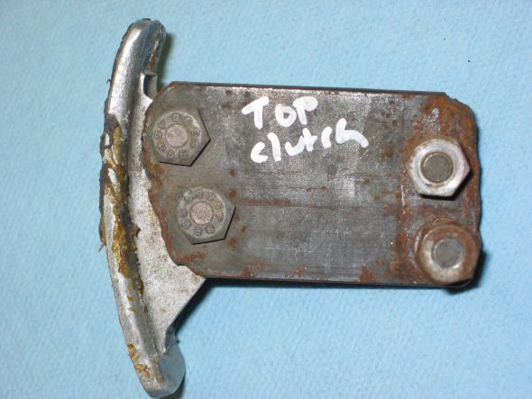
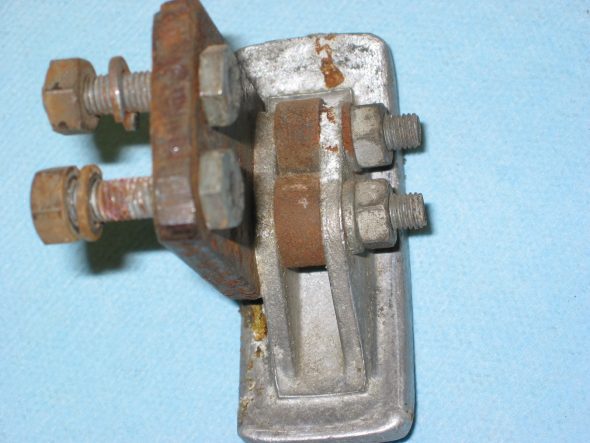
The Support Block and Clamp for Mounting of Servo to the Front Wing Valance is comprised of the curved clamp with two 1/4″ – 28 x 1″ hex head bolts spot welded to the clamp connected through the aluminum block, a rubber grommet with a metal spacer into the valance and two hex nuts with shakeproof washers.
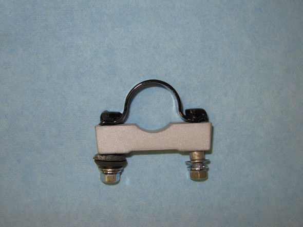
Support Block & Clamp

Support Block & Clamp

Air Cleaner for Brake Vacuum Servo

I did clean up and paint the rusted air cleaner.
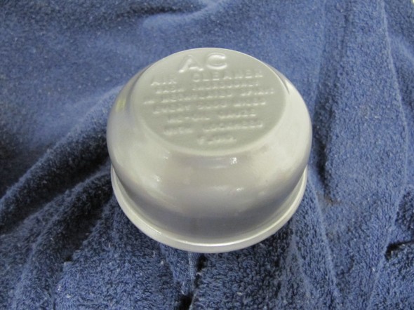
Air Cleaner for Servo

Air Cleaner for Servo

I purchased a new Hose from the Brake Vacuum Servo to the air cleaner and cleaned up and painted the Supporting Clip that used a hex head #10 – 32 x 1/2″ bolt, shakeproof washer and hex nut to tighten the clamp on the hose and air cleaner.
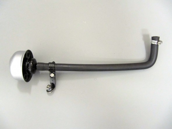
Air Cleaner, Hose, Support Clip and Clip for Vacuum Servo

Air Cleaner, Hose, Support Clip and Clip for Vacuum Servo


Brake Servo Vacuum

I purchased vacuum hose from XKs Unlimited and was very pleased with the fabric covering on the hose that looks very original. I also cleaned and cad plated the original 9/16″ clamps.
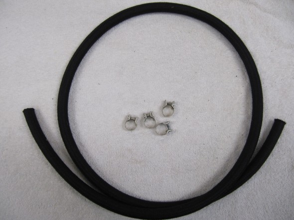
Vacuum Hose and Clamps

Vacuum Hose and Clamps


Brake Servo Vacuum Pipe

The Pipe is connected to the top rear of the inlet manifold and routes to the servo parallel to the cylinder block. The pipe is paired with the Front Return Pipe for the Heater and secured to the side of the block with the same brackets (see https://valvechatter.com/?p=4681). I loosened the flaired pipe fitting nut and removed the pipe.
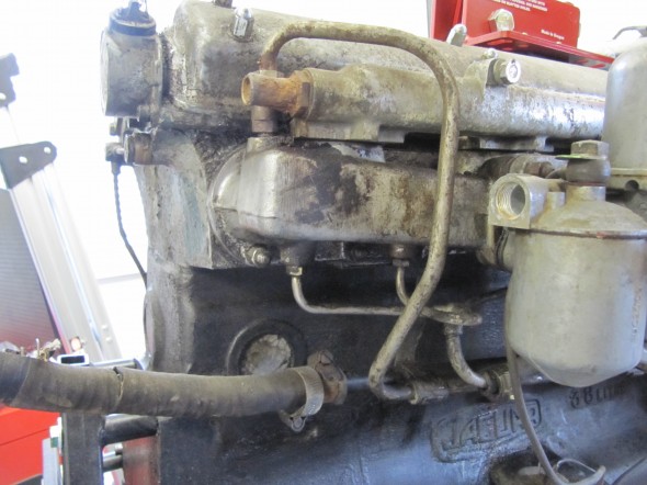
Front Return Pipe at Side Of Cylinder Block

Vacuum Pipe Mounted to Inlet Manifold
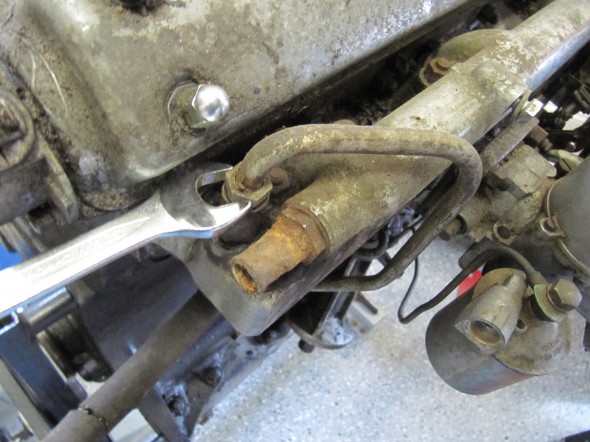
Servo Vacuum Pipe
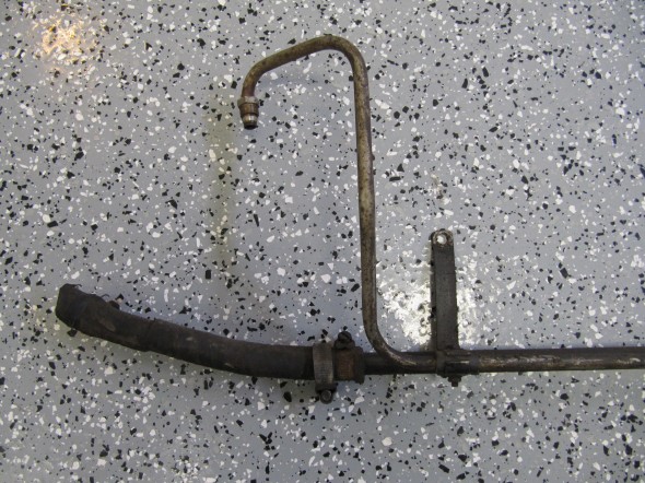
Servo Vacuum Pipe
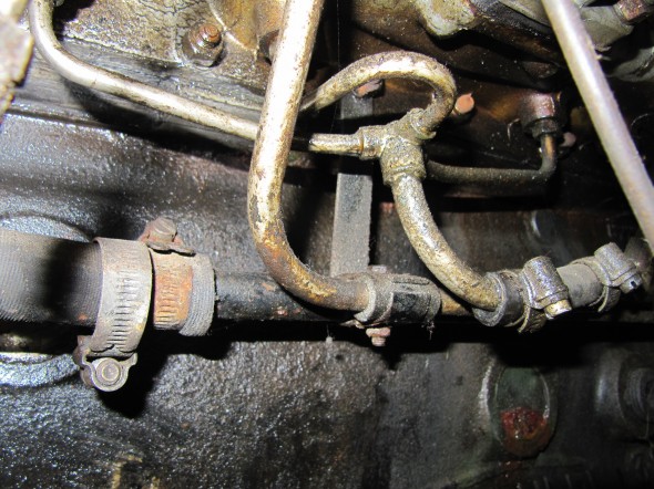
Servo Vacuum Pipe

Servo Vacuum Pipe

Rear View

Rear View

This is the pipe after cleaning and zinc plating.
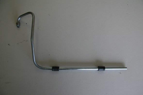
Brake Servo Vacuum Pipe Re-zinced

Brake Servo Vacuum Pipe Re-zinced

Hydraulic Lines

Calipers

The two front caliper hoses were replaced with Goodridge stainless steel braided hoses sourced from Coopercraft in England. These hoses use different size fasteners than the original rubber hose.
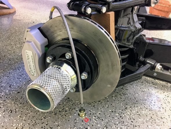
Goodridge Stainless Front Caliper Brake Hose
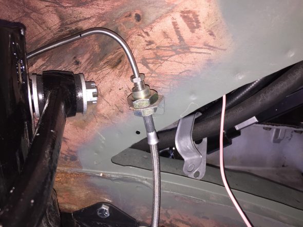
LH Front brake hydraulic line junction to caliper

After examining the image above, a fellow MK2 owner, Bruce Murray, pointed out to me that the hard brake line fitting was not threading very far into the flexible stainless steel hose emanating from the caliper and certainly not as far as one can observe with the original Girling hoses/fittings. Upon closer examination I concurred with his assessment that this is not an ideal situation. I am not saying that this is unsafe or that the arrangement won’t work satisfactorily; however, in my view one shouldn’t be taking any chances with braking systems. I like the claimed improved performance of stainless steel brake hoses and I like their looks, but I am going to switch to standard rubber hoses. An alternative would be to cut the hard line and install a fitting appropriate to the stainless steel flex line, but I will just go with the rubber hoses.

I will post more comparative information when my rubber hoses arrive.  

Rear Axle

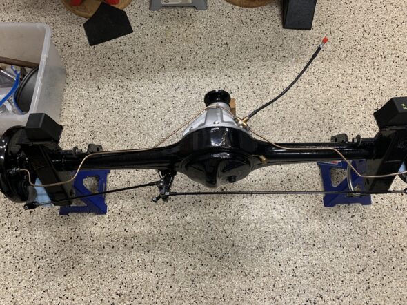
The hydraulic pipes connecting the rear brakes travel along the rear axle and are held in place by three clamps with 1/4″ – 28 x 1″ cheesehead screws and hex nuts and shakeproof washers. A flexible hose is used to connect the long hydraulic pipe that runs the length of the right hand side of the frame to the axle piping. The original hose was provided by Lucas and was rubber, and I had planned to use a Goodridge stainless flexible hose replacement that was sourced from Coopercraft in England. However, for the reasons stated above regarding the stainless hoses for the calipers, I will revert to the rubber hose upon final installation.
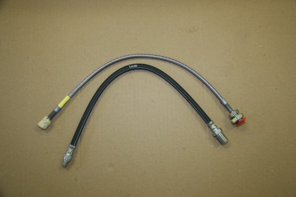
Rear Flexible Brake Hose Lucas Rubbere and Goodridge

Rear Flexible Brake Hose Lucas Rubber and Goodridge
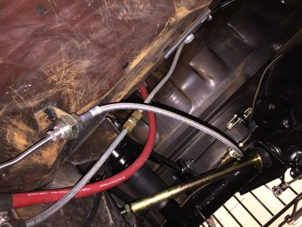
Goodridge Stainless Flexible Hose from Pipe to 3-way Adaptor with Copper Gasket Installed
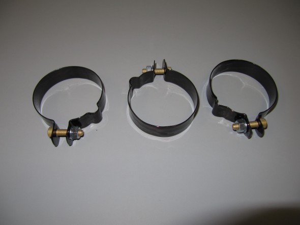
Clips Securing Hydraulic Pipes to Rear Axle

Clips Securing Hydraulic Pipes to Rear Axle

Hydraulic Pipes

I took the more expensive, but much easier way out with the hydraulic pipes and purchased pre-bent stainless steel piping. The fit on several pieces was actually not very close but eventually everything was installed.

Clutch

There are two clutch hard lines. One from the master cylinder to a firewall brace and the other from the firewall to the slave cylinder.  
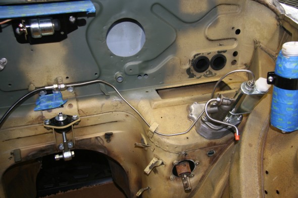
Clutch Pipe from Master Cylinder to firewall
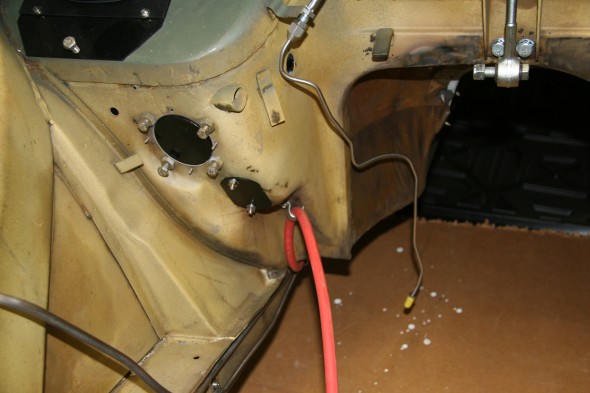
Clutch Pipe from Master Cylinder to firewall

Clutch Pipe from Firewall Mount to the Slave Cylinder

Clutch Pipe from Firewall Mount to the Slave Cylinder

Brakes

Master Cylinder

Note in the photos above that I have the master cylinder rotated 180 degrees from its position when I removed it from my car. See photo below:
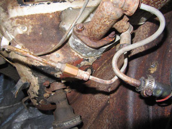
Master Cylinder and Hydraulic Pipe with fitting

The original arrangement used an intervening pipe, a coupler, and a banjo fitting to the master.
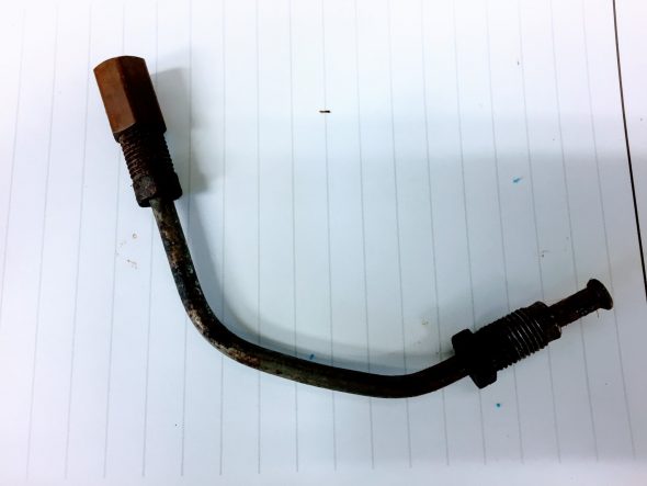
Master Cylinder Connection Pipe and Fittings

I am no expert on brake hydraulics, but it seemed to me that the use of the connection pipe introduces at least three additional opportunities for fluid leaks as compared to a direct mounting of the brake pipe from the master to the 4-way junction or union. 

Consequently, I decided to cut the end of the hard pipe coming from the 4-way union, fit a new SAE fitting nut, re-flare the end of the pipe with a new double flare and screw the pipe directly into the master. To make this easier to accomplish, I rotated the master the 180 degrees.

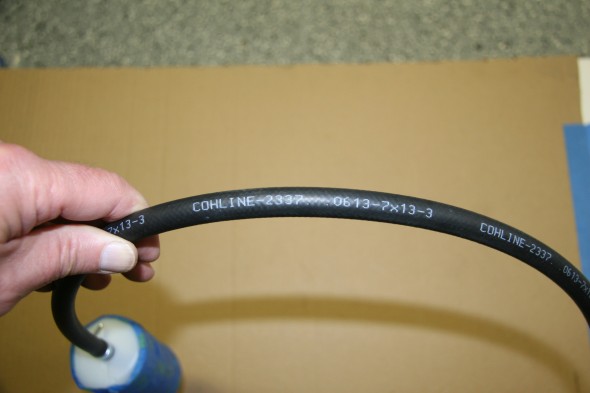
Brake Pipe from Reservoir Through Flexible Hose to Master Cylinder – This short pipe is joined to a hose specifically designed for use with hydraulic fluid that connects to the brake fluid reservoir. The hose was sourced from SNG Barratt COH Line – 2337, 0613-7 x 13-3. SNG Barratt supplied a 5/8″ clip to secure the hose, but I found the clip to be too large and instead used 11-13 mm clips at both ends of the hose. The plastic reservoir is taped to keep it clean while mounted in the car during restoration.
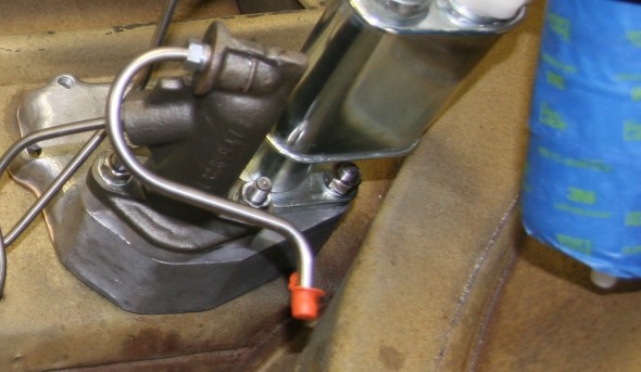
Brake Pipe From Master Cylinder to Flexible Hose
Brake Pipe From Master Cylinder to Flexible Hose

Brake fluid Hose from Reservoir to Master Cylinder Pipe
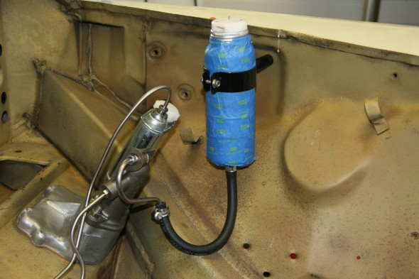
Brake fluid Hose from Reservoir to Master Cylinder Pipe

Brake Fluid Hose from Reservoir to Master Cylinder Pipe

Brake Fluid Hose from Reservoir to Master Cylinder Pipe

Brake Pipe From Master Cylinder to Four-Way Junction – This pipe curves around the firewall, along the RH engine bay valance and connects with the junction. It is held in place by two welded folding clips.
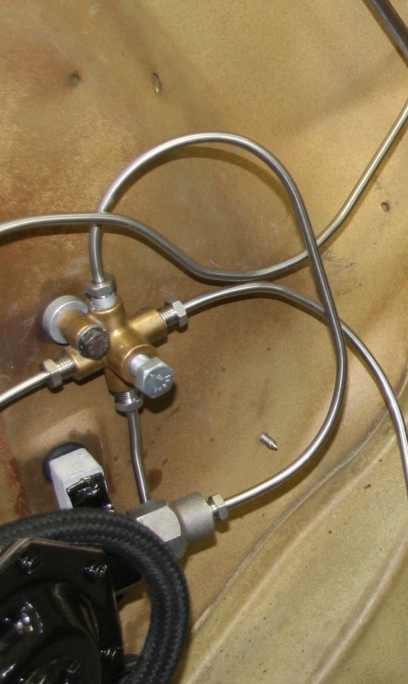
Brake Pipe from Servo to the Four-Way Junction

Brake Pipe from Servo to the Four-Way Junction

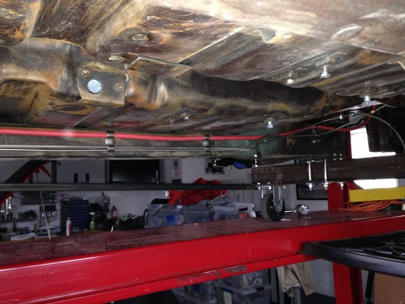
Brake pipe to rear axle from from-way adapter – A long pipe running from the four-way adapter, along the RH frame rail to a metal tab fitting welded to the body at the end of the frame connects to a flexible Goodridge hose to the rear axle. This pipe shares routing with the full line and battery cable, all secured by a series of stainless steel double clips.
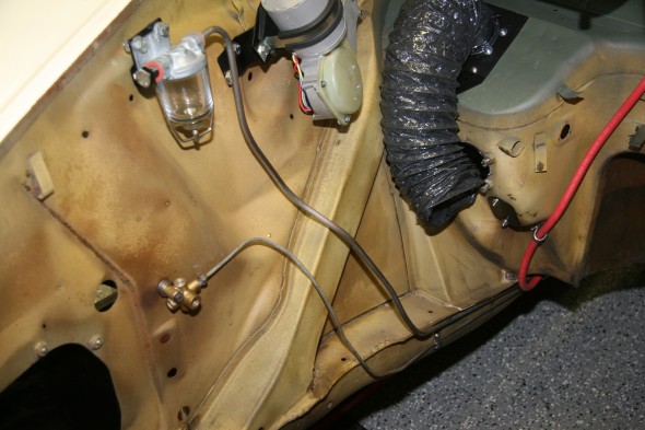
Fuel and brake Lines routed to Rear
Fuel and brake Lines routed to Rear

Fuel Line, Brake Pipe, Battery Cable Routing
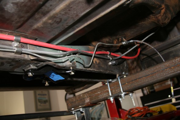
Fuel Line, Brake Pipe, Battery Cable Routing

Brake Line Connection to Flexible Hose

Brake Line Connection to Flexible Hose

LH Front Brake Pipe – This line runs from the four-way adapter, around the front frame under the radiator, and through a LH engine bay valance rubber grommet, to a welded metal clip on the outside of the valance where it joins a Goodridge flexible hose to the brake caliper. It is secured by three white zinc 1/4″ clips with 7/32″ holes and  stainless self-tapping screws. A bendable tab at the front center of the frame helps to hold the pipe in place.
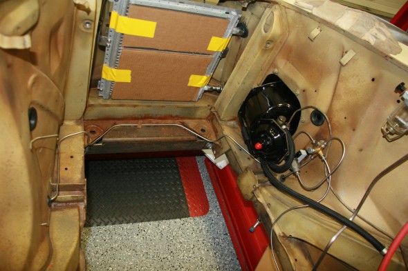
LH Brake Pipe to Junction

LH Brake Pipe to Junction

RH Front Brake Pipe – This line runs from the four-way adapter, through a RH engine bay valance rubber grommet, to a metal welded clip on the outside of the valance where it joins a Goodridge flexible hose to the brake caliper. It is secured by one white zinc 1/4″ clip with a 7/32″ hole and a stainless self-tapping screw.
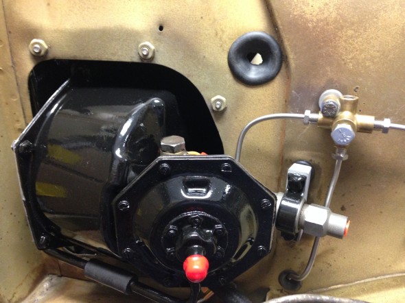
RH Front Brake Pipe From Four Way Junction to Caliper
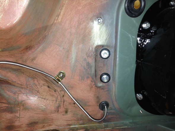
RH Front Brake Pipe From Four Way Junction to Caliper

RH Front Brake Pipe From Four Way Junction to Caliper

RH Front Brake Pipe From Four Way Junction to Caliper

Brake Pipe Tools

I will be using new pipe hardware for the Jag. This will require shaping the pipe (or straightening it), and while I have a few tools for this purpose, Brake Quip sells some very nice brake system tools and fittings.

http://www.brakequip.com/tools

Brake Fluid Container & Clip

The container and clip were replaced with new items including the filler cap and level indicator switch. The Clip has a distance piece through which a 1/4″ – 28 x 2 1/4″ hex head bolt, shake proof washer, and a hex nut are used to mount the container to the LH wing valance. A #10 -32 x 3/4″  machine screw, shake proof washer, flat washer and hex nut is used to tighten the container clamp. Both the clip and the distance piece were painted with gloss black POR-15.
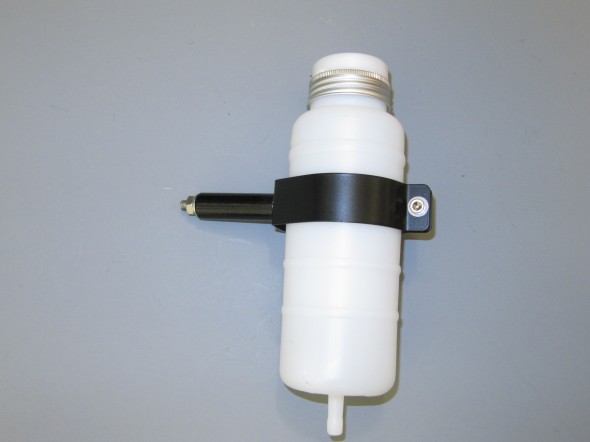
Brake Fluid Container, Filler Cap & Level indicator Switch, Clip and Distance Piece

Brake Fluid Container, Filler Cap & Level indicator Switch, Clip and Distance Piece

Brake Pipe 4-Way Adaptor

This component simply needed cleaning and it was ready to use once more:
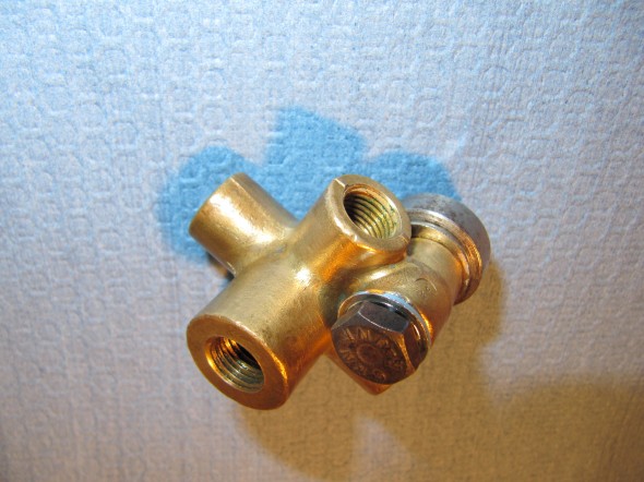
Brake Pipe 4-Way Adaptor
                                                  Brake Pipe 4-Way Adaptor

Mechanical Brake Switch

The MK2 originally used an hydraulic brake switch to activate the rear brake lights when the brakes are applied. The hydraulic switches currently available seem to experience a higher than normal failure rate. I encountered this same issue with my Austin-Healey 3000. In the Healey I replaced the hydraulic switch with a plug in the 4-way adaptor and installed a mechanical switch at the brake pedal. The wiring is the same as for the electrical switch. The mechanical switch was sourced from Watson’s Streetworks.

Watson’s Streetworks Mechanical Brake Switch
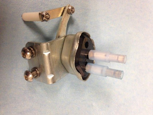
Watson's Streetworks Mechanical Brake Switch

Watson’s Streetworks Mechanical Brake Switch

Brake Servo and Cowl

The brake servo sites in a Cowl, On The RH Wing Valance Enclosing Brake Servo Unit. I cleaned this metalwork and painted it with POR-15. The Cowl fastens to the bodywork with seven 1/4″ – 28 x 1/2″ hex head bolts with accompanying flat and shakeproof washers.
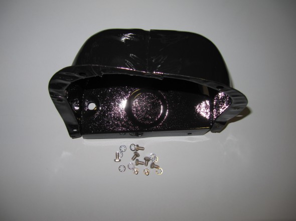
Cowl on RH Wing Valance Enclosing Brake Servo Unit

Cowl on RH Wing Valance Enclosing Brake Servo Unit

I trial fit the cowl and the Reservac with shield when building the air conditioning system. The cowl has three rubber grommets and steel spacers fitted for the studs on the servo. The steel spacers have the following dimensions: height .255″, O.D. .375″, I.D. .270″. These are secured with hex nuts and internal tooth lock washers.The servo is also supported with two studs from the Support Block and Clamp for Mounting of Servo to the Front Wing Valance referenced above.
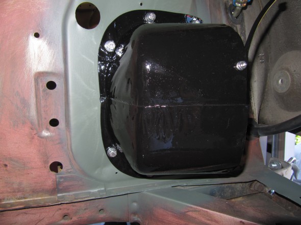
Brake Booster Cowl Mounted
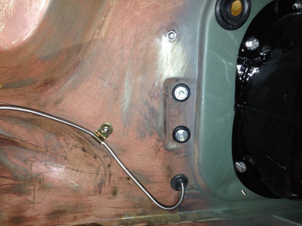
Brake Booster Cowl Mounted

Brake Servo RH Valance Grommets and Steel Spacers
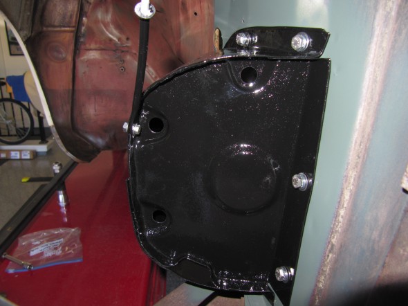
Brake Servo RH Valance Grommets and Steel Spacers

Brake Booster Cowl Mounted
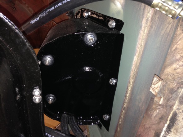
Brake Booster Cowl Mounted

Brake Servo Installed in Cowl with Breather Hoses
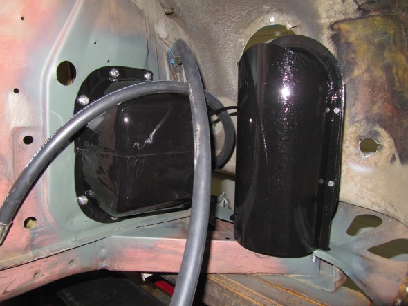
Brake Servo Installed in Cowl with Breather Hoses


Brake Booster Cowl and Vacuum Tank Mounted
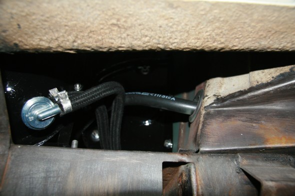
Brake Booster Cowl and Vacuum Tank Mounted

Check Valve and Breather Hose

Check Valve and Breather Hose

Brake Servo Mounted
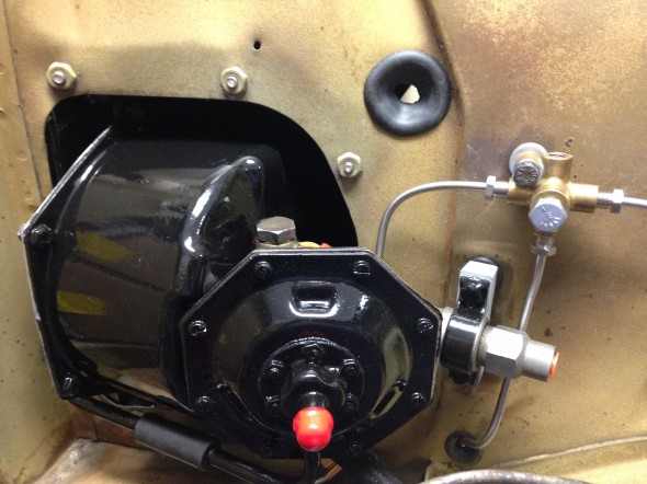
Brake Servo Mounted
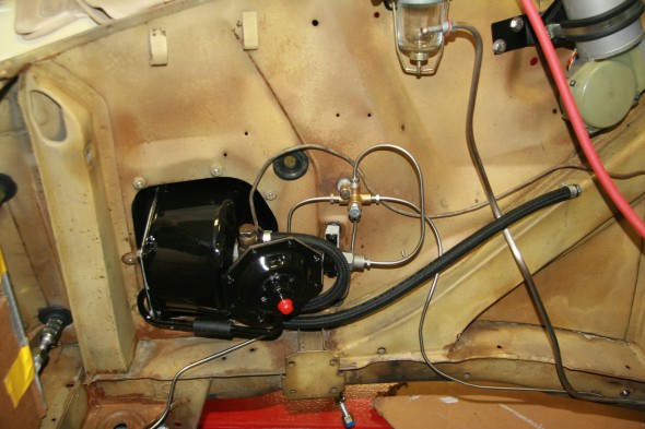
Brake Servo Mounted

Brake Hydraulic Lines at Servo

Brake Hydraulic Lines at Servo

The air cleaner will need to be secured to the radiator shroud after it is installed. The bracket has been refurbished and painted with new fasteners and a restored air cleaner is pushed onto the new rubber hose.
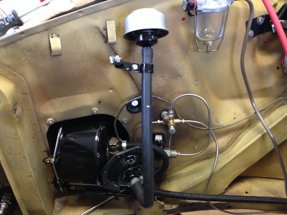
Brake Servo Breather Pipe and Air Cleaner

Brake Servo Breather Pipe and Air Cleaner

These are a few images of the Brake Vacuum Servo Air Cleaner and Hose installed after the engine and radiator are fitted.
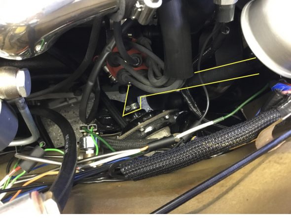
Air Cleaner Hose for Brake Vacuum Servo Hose Installed
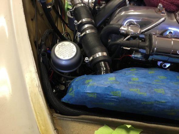
Air Cleaner for Brake Vaccum Servo installed

I thought the original support bracket mounted to the upper right stud on the radiator (shroud) held the air cleaner too close to other items that would cause rubbing so I used a 3/4″ threaded extender to move the air cleaner slightly rearward. 

Brake Pedal and Master Cylinder 

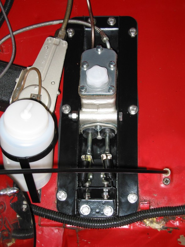
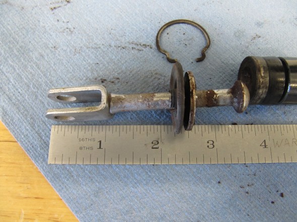
I previously removed the brake and clutch housing complete with master cylinders and pedals. To refurbish this unit, I began with disassembly of the brake components. I first separated the Girling 875 Master Cylinder from the housing. An aluminum spacer is sandwiched between the master cylinder and the housing, and held in place by two 5/16″ hex nuts and shakeproof washers on 5/16″ – 24 studs. The 5/16″ x 3/4″ clevis pin with flat washer is removed from the pedal freeing the push rod for removal.
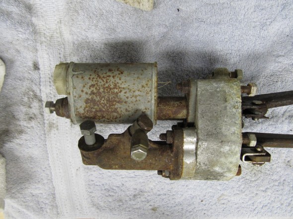
Pedal Assembly
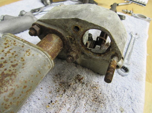
Pedal Assembly

Master Removed

Master Removed

The Girling 875 Master Cylinder has a 7/8″ bore. The master was sleeved with stainless steal and a rebuild kit with new seals was installed.
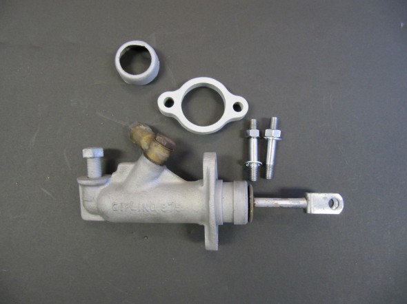
Master components
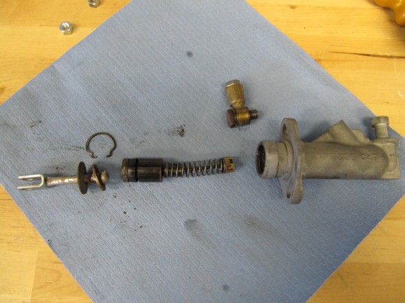
Master components

Master Components

Master Components

Push Rod Length

Push Rod Length

These images show the aluminum brake and clutch housing with the pedals, return springs and fibre washers.
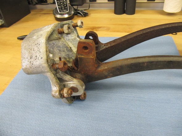
Pedal Housing
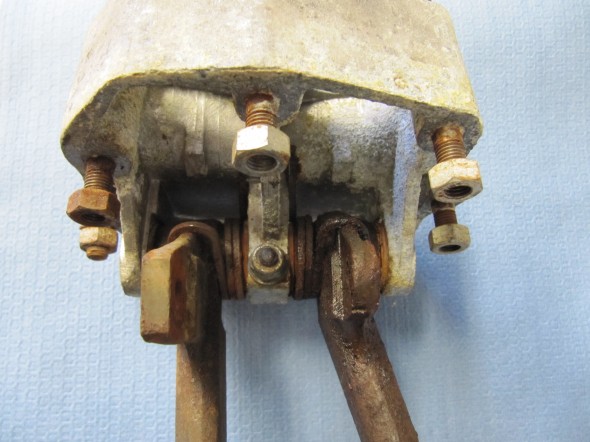
Pedal Housing

Pedals in Housing

Pedals in Housing

Return Springs

Return Springs

The clutch master cylinder and reservoir removal is described under the “Gearbox and Clutch” post found at this link: https://valvechatter.com/?cat=639.

After the clevis pins are removed, the 1/4″ – 28 x 1 1/2″ hex bolt and nylock nut can be removed from the central pedestal. This bolt holds the pedal shaft in place. The shaft was then knocked out with a punch and hammer. Each pedal could then be removed along with the return springs and two fiber washers for each pedal. All parts were cleaned and the housing was then reassembled.
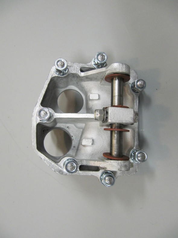
Brake & Clutch Master Cylinder Housing and Pedals
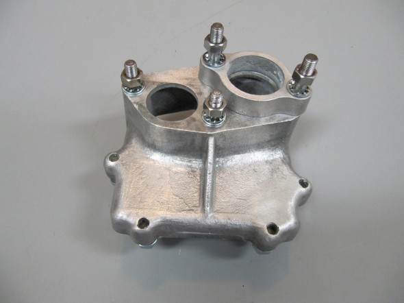
Brake & Clutch Master Cylinder Housing and Pedals


Brake & Clutch Master Cylinder Housing and Pedals

Brake & Clutch Master Cylinder Housing and Pedals

Seven 5/16″ – 24 studs are located in the housing to secure the assembly to the car’s body structure with hex nuts and a double paper gasket (two gaskets).

I had some difficulty ordering new pedal return springs for the clutch and brake pedals, but after several weeks I finally received the proper parts. I first placed the twin paper gaskets that go between the master cylinder housing and the body on the housing (you cannot get it on after the pedals are on the shaft). I then installed the freshly painted pedal arms and pedals along with new rubber pedal pads. The clevis pins were in good shape so I simply cleaned them up, greased them and reinstalled with new split pins. I then placed the new clutch master cylinder/reservoir on the studs on the housing and tightened the two nuts and shake proof washers.
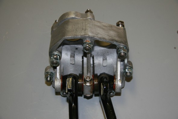
Master Cylinder Housing
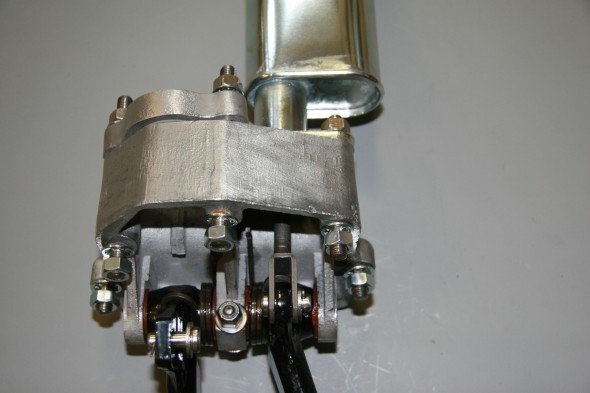
Master Cylinder Housing

Pedals mounted to Housing
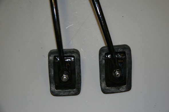
Pedals mounted to Housing

New Pedal Rubbers
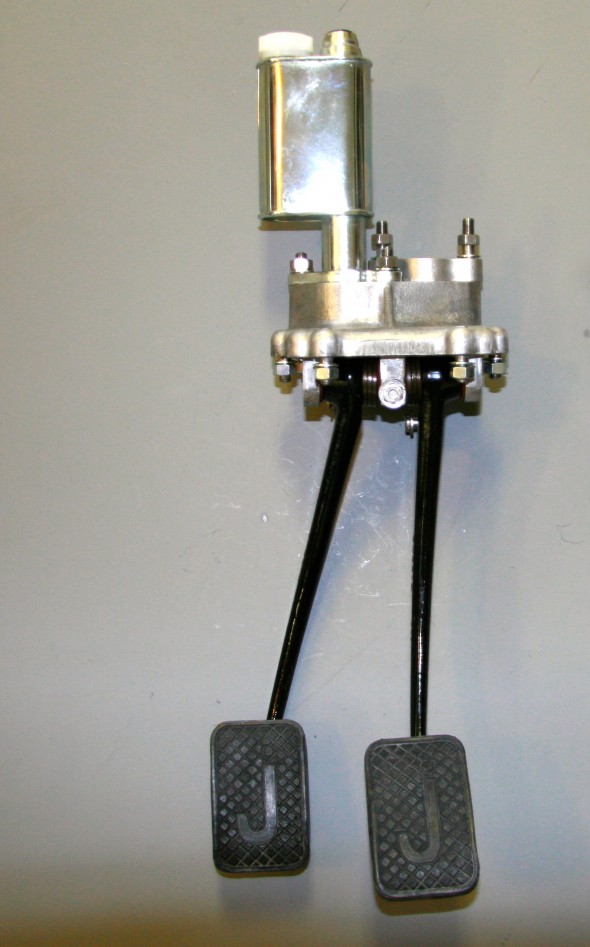
New Pedal Rubbers

Clutch Master Cylinder, Reservoir Mounted to Housing with new Pedal Rubber

Clutch Master Cylinder, Reservoir Mounted to Housing with new Pedal Rubber

The pedal assembly was installed in the car. A double gasket was mounted between the aluminum base and the car body. The assembly can be inserted through the hole in the body if the pedal pads are removed. After installation the brake master was fitted and the clevis and split pin were inserted to connect the pedal to the master cylinder push rod.
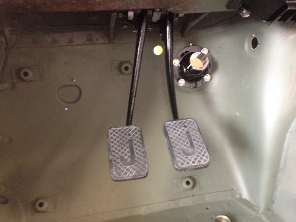
Pedal Assembly Installed

Pedal Assembly Installed

Bleeding the Hydraulic System

After checking all of my connection points one more time to make sure everything was tight, I put a couple of inches of DOT 4 brake fluid into the fluid reservoir and let that drain for a few minutes to see if I had any leaks close to the reservoir. It turned out that I did, but I was able to take care of that in fairly short order. I then filled the reservoir and let gravity work its magic for about thirty minutes. 

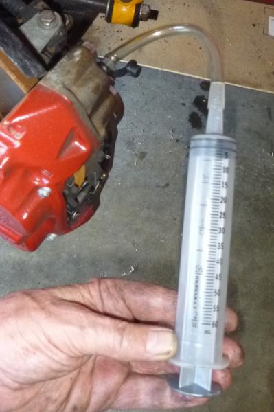
I like to use a syringe to pull fluid through the pipes to the bleeder valves. I use one like this with a clear hose about 10″ long to connect the syringe to a bleeder valve.
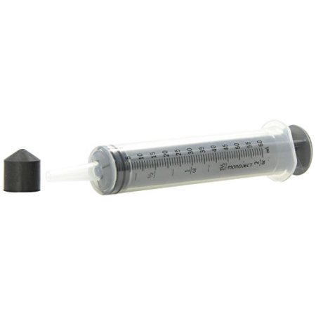
Brake Fluid Syringe

I find that using the syringe speeds up the bleeding process. Everyone has their preferred ways of bleeding. I put some grease around the bleeder screws to help prevent any air from entering the system through the bleeder threads and then I attach the syringe hose to the bleeder, crack open the valve and slowly pull the syringe extracting air and ultimately fluid from the line.

I start with the LH rear bleeder, move to the RH rear bleeder, then the LH front bleeder and finally the RH front bleeder. In this fashion I move from the bleeder farthest away from the four-way hydraulic junction mounted on the RH engine bay valance to the closest.

Since my system was completely dry, I had to suck air out of the LH rear bleeder valve five or six times before I began to draw fluid with the air bubbles. I would open the bleeder, draw the syringe, close the bleeder, and release the syringe tube from the bleeder to push the syringe piston fully downward in the cylinder and expel the air. I would then reconnect to the bleeder and repeat the process. The LH rear bleeder valve always takes the longest. Each successive bleeder takes fewer and fewer applications of the syringe. 

After completing the process, I still ask for the assistance of my wife to push the brake pedal for me as I continue to monitor each of the brake bleeders in the same sequence. I open a bleeder valve, she pushed the pedal down and leaves it down. I then close the valve and tell her to release the pedal upward. I then open the valve again and she pushes to the floor once more and that process continues until all air is expelled.

For the “pedal pushing process” I use a small container with fluid in the bottom and a short clear hose to collect the fluid that is expelled from each bleeder. Because the syringe process gets the vast majority of air out of the system, the “pedal pushing” takes very little time. I find that my spouse prefers this two step method of the syringe followed by pedal pushing because it keeps her in the garage for much less time than when one relies on “pedal pushing” alone!

Fortunately, we encountered no additional leaks and the process produced a nice firm pedal. 

I then basically replicated the process for the clutch. The slave cylinder can at times be a challenge and I find drawing the fluid through the slave with the syringe is particularly helpful. Once I got a good flow of fluid through the slave cylinder, my able assistant used the “pedal pushing process” to finish the job once more. Again, with positive results. 


Gearbox, Clutch and Propshaft

Clutch and Gearbox

Clutch Master Cylinder

I will replace the master and reservoir seen here with a new unit.

Clutch Master/Reservoir

Clutch Master/Reservoir

Clutch Master/Reservoir

Clutch Master/Reservoir

Since the clutch master and the brake master share the same housing and pedal box, information about those components is addressed under the brake servo and hydraulics post at this link: https://valvechatter.com/?cat=615

Clutch Master Cylinder, Reservoir Mounted to Housing with new Pedal Rubber

Clutch Master Cylinder, Reservoir Mounted to Housing with new Pedal Rubber

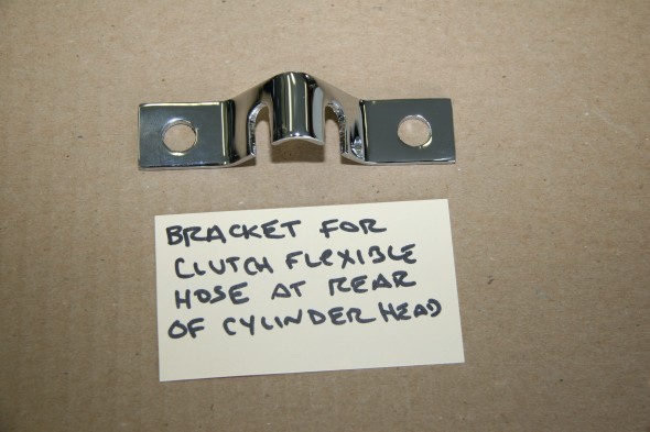
Bracket for Flexible Clutch Hose at Rear of Cylinder Head

This little bracket is in a conspicuous location and called for re-chroming.

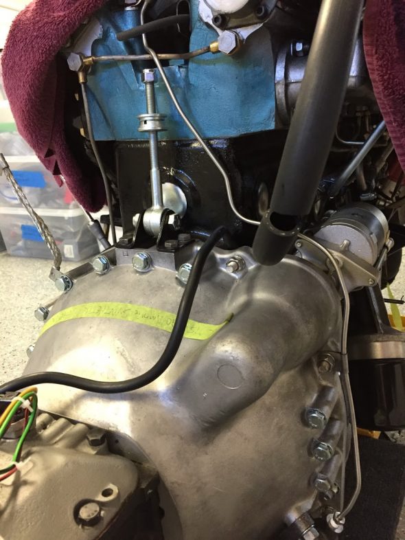
Clutch Flexible Hose Bracket at Rear of Cylinder Head

Clutch Flexible Hose Bracket at Rear of Cylinder Head

Slave Cylinder Hydraulic Pipe

A hard line attaches to the flexible stainless steel hose at the cylinder head bracket (shown above) and connects to the slave cylinder. It is held securely by one clip attached to the bell housing. The new line was sourced from Classic Tube along with the pre-bent brake lines.

Slave Cylinder Hydraulic Line

Slave Cylinder Hydraulic Line

Clutch

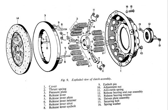
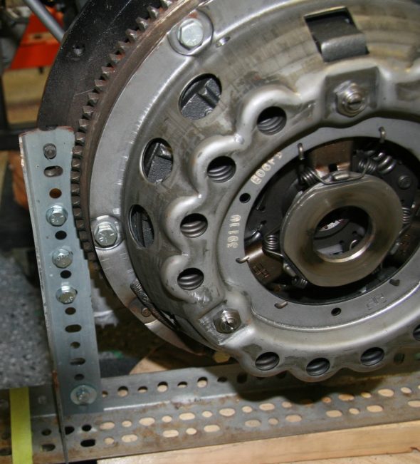
The 1964 MK2 used a spring-loaded, hydraulically-operated, driven plate assembly with cover and a graphite release bearing. Later models switched to a diaphragm clutch. While the diaphragm cultch is probably easier to operate, I decided to stick with the original type in my restoration. The entire clutch assembly was purchased from SNG Barratt and installed by my engine builder, Mike Gassman, from Gassman Automotive. The unit was balanced with the engine for smoother running.

MK2 Clutch Diagram

MK2 Clutch Diagram

MK2 Clutch Assembly

MK2 Clutch Assembly

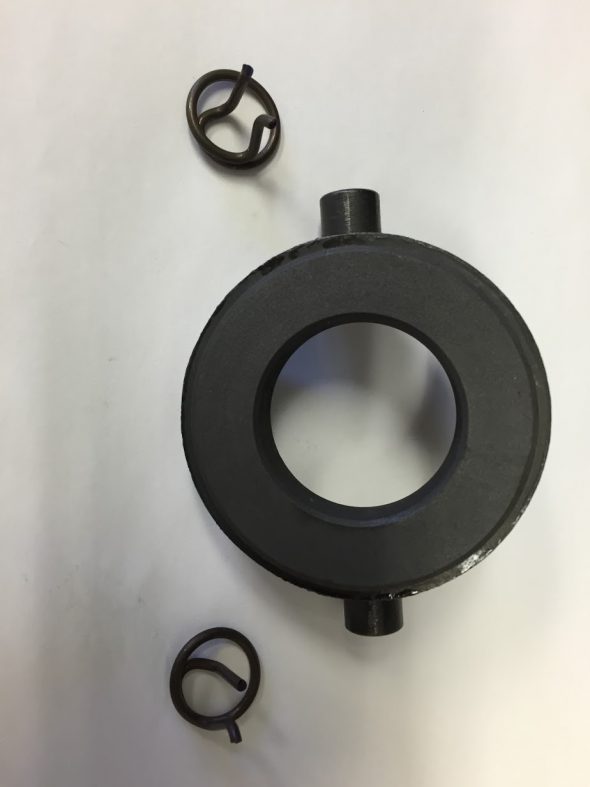
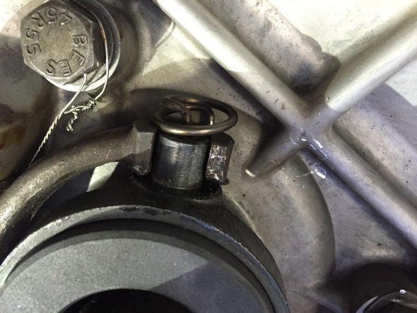
Release Bearing and Clips

Release Bearing and Clips

Release Bearing Mounting Clips

Release Bearing Mounting Clips

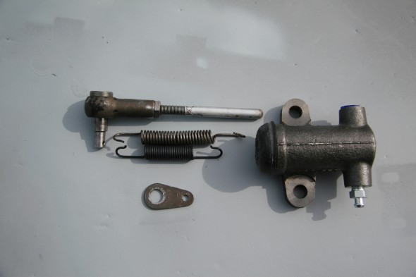
Clutch Slave Cylinder

Fortunately, the replacement slave cylinder sourced from SNG Barratt is exactly the same as the original. the rubber boot is somewhat different, but otherwise identical. The new return spring is; however, shorter than the spring currently on the car. Not sure if it is a different spring or if the original is stretched. In any case, I shall try the new one (which did have the proper Jaguar part number) and see how everything functions.

Slave Cylinder Assembly

Slave Cylinder
Assembly

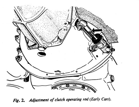
The Jaguar Service Manual states that “there should be 3/4″ free travel or unloaded movement at the pedal pad before feeling the resistance of the clutch thrust springs. The free travel is most easily felt by depressing the pedal pad by hand until a marked resistance is felt. Adjustment is effected by slackening the lock nut and turning the operating rod between the slave cylinder and the clutch withdrawal lever. Screwing the rod into the knuckle joint will increase the pedal travel; screwing the rod out will decrease the free travel.”

MK2 Clutch Slave Cylinder Adjustment

MK2 Clutch Slave Cylinder Adjustment

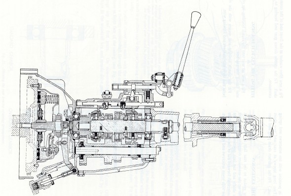
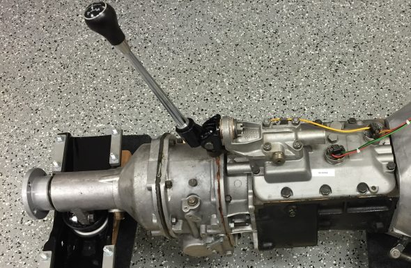
Gearbox and Overdrive The gearbox is a four-speed type with synchromesh on the second, third, and top gears. The overdrive is a Laycock de Normanville. First and reverse gears are 12.731:1, Second is 7.012:1, Third is 4.836:1, and fourth is 3.77:1; with the overdrive engaged the top gear ratio is 2.933:1. A synchronized fiord gear was added later in production.

According to Nigel Thorleys excellent book – Original MK1/MK 2 the all synchro box was fitted in Sept 1965 from chassis no 119200 – 2.4 RHD 127822 – 2.4 LHD 169341 – 3.4 RHD 180188 – 3.8 LHD

MK2 Gearbox

MK2 Gearbox


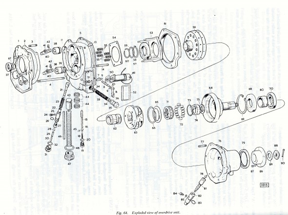
MK2 Overdrive

MK2 Overdrive

Mike Gassman, http://www.gassmanautomotive.com refreshed the overdrive and the gearbox was sent to Quantum Mechanics in Connecticut. Both units were in good repair with the exception that the 3rd to fourth shift fork was bent and was replaced. The gearbox also had all bearings, synchronizers, seals and gaskets replaced. The gears were in good shape. The overdrive was cleaned, an overdrive rebuild kit installed and reassembled in good working order. A new solenoid was affixed and the system was tested.

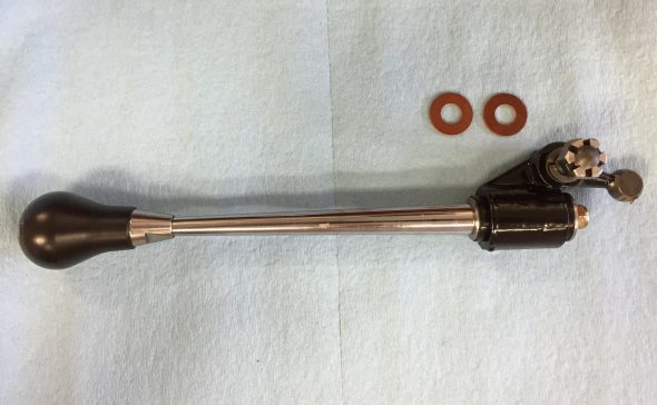
Change-Speed Lever Assembly (Gear Shift) The  change-speed lever has single flat washer above the selector lever.

There is a two part rubber bush inside the selector lever through which the selector shaft passes. There is a flat washer at each end of the bush. The washers have different diameter holes appropriate to the shaft size at each end of the lever. I cleaned the selector lever and painted it with POR-15. New rubber bushes were also installed.

Change-Speed Lever

Change-Speed Lever

Selector Lever

Selector Lever

Painted Selector Lever

Painted Selector Lever

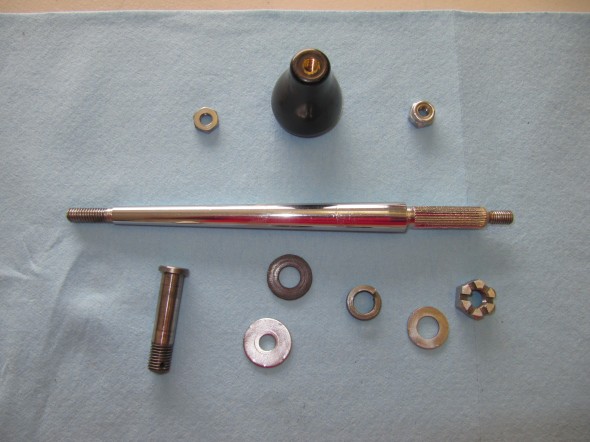
Assembly Components

Assembly Components

There is a bronze bushing in the selector lever through which the pivot pin passes. This bush was also replaced with a new component. A new fiber washer is located on each end of the pivot pin. A double spring washer  is located on the pivot pin and the assembly is held together with a slotted nut and a split (cotter) pin.

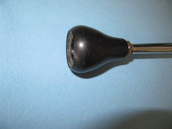
Change Speed Lever Knob

Change Speed Lever Knob

The correct lever knob for the early Moss gearbox (without first speed synchro) is a tear drop shape. The later box used a round shifter ball. A locking nut secures the shift knob to the shaft.

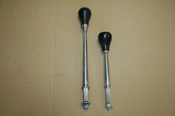
I ordered a new lever shaft and discovered that what is being supplied now is 3 inches shorter than the original. I will probably have my original lever shaft rechromed and use it.

Original Shifter on Left and New Part on Right

Original Shifter on Left and New Part on Right


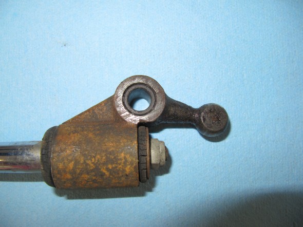
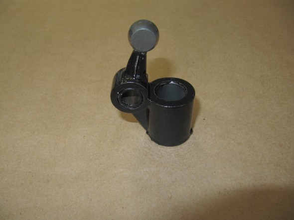
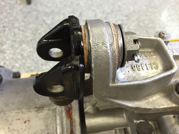
Pivot Jaw Holding Selector Lever

This device connects the Change-speed Lever (gear shift) to the Gearbox Top Cover. In the image below it is the black yoke which was cleaned and painted with POR-15.

Pivot Jaw Housing Selector Lever

Pivot Jaw Housing Selector Lever

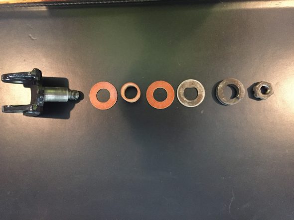
The following image shows the components of the Pivot Jaw assembly: The Pivot jaw, two fibre washers, a bushing, a flat “D” washer, a spring washer and a slotted nut with split pin.

Pivot Jaw Assembly Components

Pivot Jaw Assembly Components

This image shows the Pivot Jaw Housing, the Change-speed Lever, and the Selector Lever all assembled and in place on the gearbox:

Assembled Gear Selector Assembly

Assembled Gear Selector Assembly

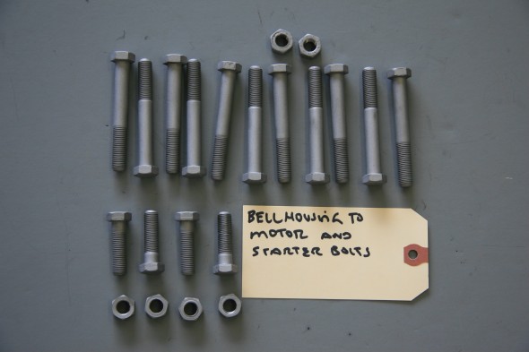
Fasteners for Gearbox to Engine The original fasteners were in good shape, no doubt due to the thick coat of oil and grease that encapsulated them! I media-blasted the bolts and nuts and had them zinc plated for use upon reassembly. There are eleven hex head bolts 3/8″ – 24 x 2 7/8″ with two 3/8″ – 24 nuts and shakeproof washers, and four 3/8″ – 24 x 1 3/8″ hex head bolts with four 3/8″ – 24 nuts and shakeproof washers.

Bellhousing fasteners

Bellhousing fasteners

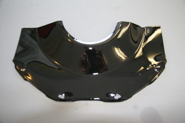
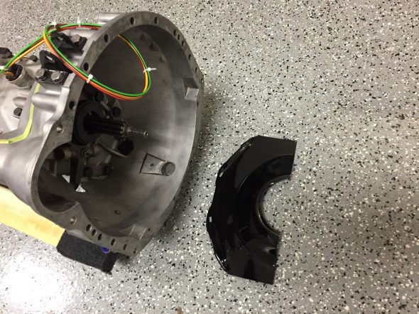
Cover Plate at Front of Clutch Housing  The cover plate is fastened to the engine backplate with four #10-24 x 1/2″ hex head bolts and shakeproof washers. It is installed when the gearbox is mated to the engine when the two components are separated by approximately 2″. At that time the cover plate is slid into position and tightened against the lip of the gearbox bell housing with the four bolts.
Clutch Cover Plate

Clutch Cover Plate

Clutch Cover Plate at Bell Housing

Clutch Cover Plate at Bell Housing

Gearbox/Engine Mating

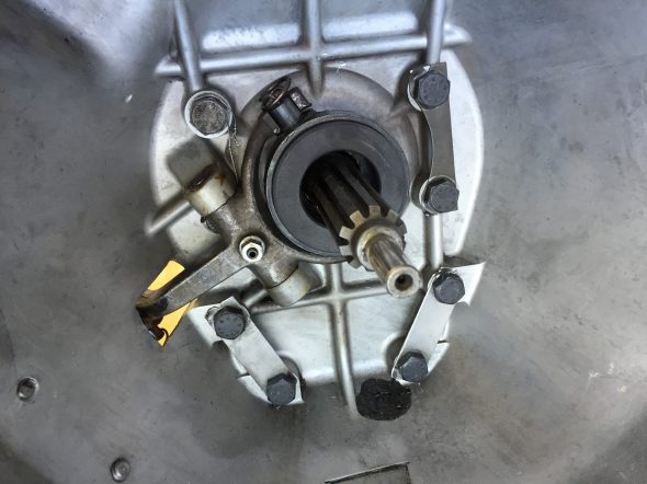
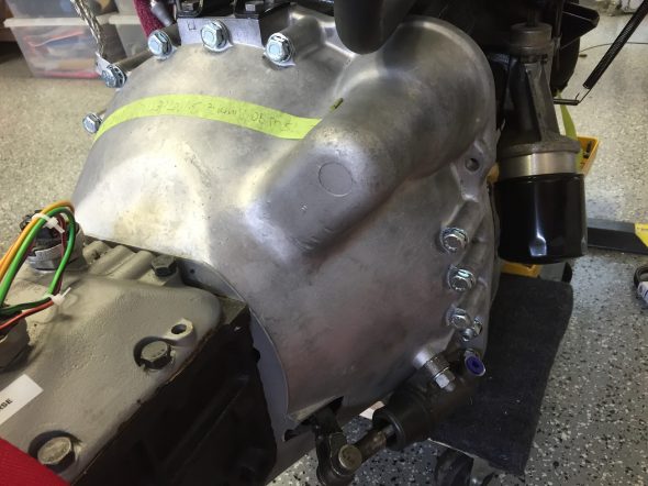
On June 18, 2016 in preparation for the preliminary installation of the engine and gearbox into the car for testing, I mated the two components together using the bolts referenced above. In the cases where nuts are used, all nuts are found on the bell housing side. I had to wrestle with the gearbox a bit to get it to seat properly, but I eventually got there. One must be careful to keep the gearbox mainshaft level with the crankshaft to avoid bending the shaft.

Gearbox Mainshaft

Gearbox Mainshaft

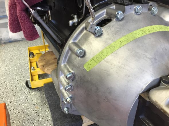
I used my engine hoist to hold the gearbox at proper height during the exercise. Several long 3/8″ bolts were used to align the bell housing and the backplate of the engine, prior to inserting the proper bolts and pushing the gearbox home. As mentioned above, then the two components are approximately two inches apart, the clutch cover needs to be inserted and bolted in place.

RH Side of Bell Housing Mounted to Engine

RH Side of Bell Housing Mounted to Engine

LH Side Of Bell Housing Mounted to Engine

LH Side Of Bell Housing Mounted to Engine

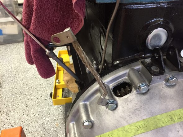
Ground Strap

The ground strap was connected to the engine/bell housing prior to installation in the car. A new ground strap was sourced from SNG Barratt. Note the proper location of the strap:

Ground Strap Mounted

Ground Strap Mounted

Propshaft

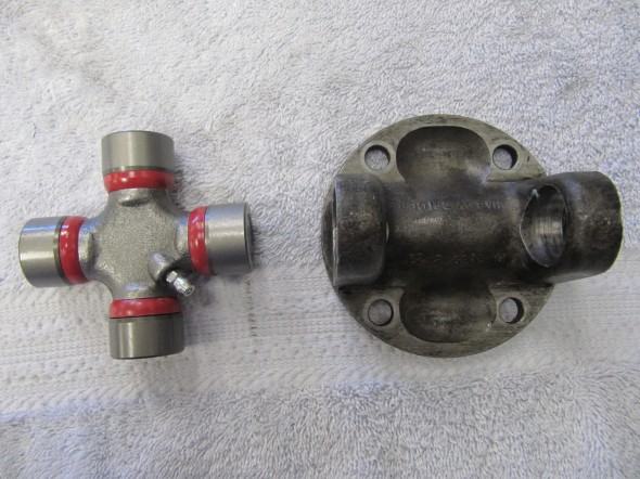
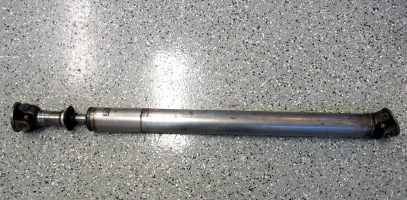
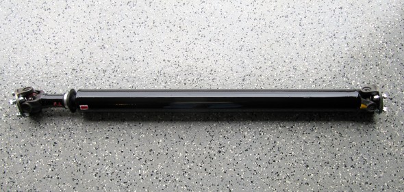
The propshaft with the two flange yokes attached is just under 48″ long. The shaft seems to be in good shape, but I went ahead and replaced the two universal joint journals and bearings. Following installation of the universal joints I greased the two units and then cleaned the shaft well to send to Driveshaft Specialists in San Antonio, TX  http://www.driveshaftspecialist.com  (Jeff, 866-455-6622) for balancing.

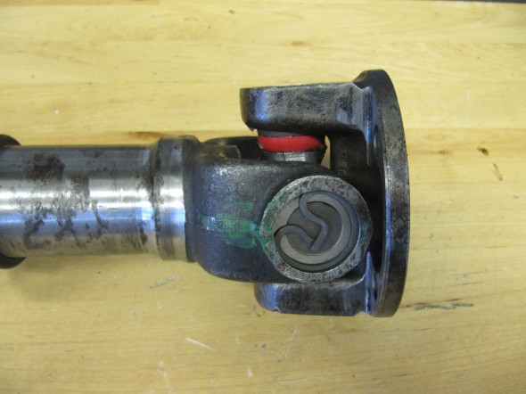
Universal Joint Replacement

Universal Joint Replacement

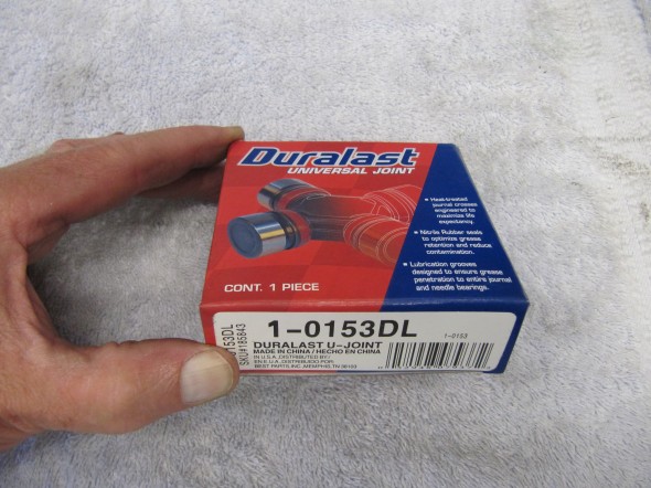
Duralast Universal Joints

Duralast Universal Joints

Universal Joints Installed

Universal Joints Installed

Upon return from Driveshaft Specialists, I painted the propshaft with POR-15.

Propshaft with new Universal Joints

Propshaft with new Universal Joint

Balanced & Painted Propshaft

Balanced & Painted Propshaft

Gearbox/Overdrive Lubrication

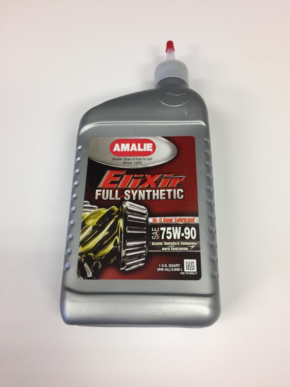
After installing the engine and gearbox in the car I filled the gearbox and overdrive with oil. Mike Gassman, at Gassman Automotive, recommended using Amalie Elixir Full Synthetic GL-5 Gear Lubricant. The Jaguar MK2 Service Manual indicated that 4-3/4 pints of lubricant should be used.

Amalie Elixer Full Synthetic GL-5 Gear Lube 75W-90

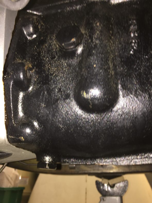
This image, although a little out of focus, shows the fill plug near the top and the drain plug at the bottom of the gearbox. The overdrive fills though an internal hole from the gearbox to the overdrive.

Drain and Fill Plugs for the Jaguar MK2 Gearbox

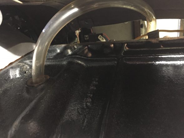
While I could have used my hand pump to pump the gear lube from below into the fill hole, since my interior is not installed I removed the fiberglass gearbox cover and filled from above. I inserted a clear tube into the fill hole and routed it to the interior. I found that it actually took a little closer to 4- 1/2 pints to fill the units, even after waiting some time to allow the fluid to flow to the overdrive. I filled the gearbox until the gear lube began to leak out of the fill hole.

Fill Tube for Gearbox


Bloody Beast Maintenance

Maintenance

October, 2014 – 

Returning home from the Shenandoah Valley British Car Club show in Waynesboro, VA I noticed that the clutch pedal was slippery. Sure enough the seals in the master cylinder failed and I had some nasty brake fluid leaking from the cylinder. I removed both the brake and clutch masters figuring that I might as well rebuild them both at the same time. Both were brand new when installed in the car, so other than cleaning the bores I did not bother with a full rebuild including honing or lining the bores. I have fewer than 12,000 miles on the originals, but it has been five or six years and who know how long they were on the shelf before I installed them?

Both of my masters were 5/8″ bores and I decided to purchase a new 3/4″ bore for the brake system. Ordered one from British Parts Northwest.

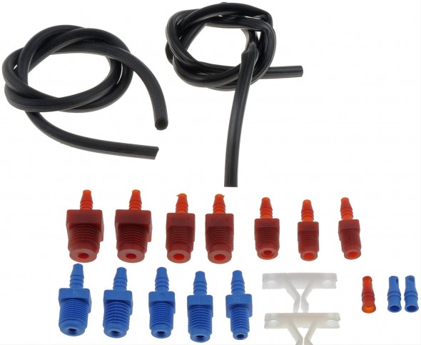
In preparing to bench bleed the two masters I decided to purchase a little “HELP” kit from Summit Racing for all of $6.00. I did substitute clear hose for the black vinyl so that I could observe the air bubbles flowing to the fluid reservoir. The Healey master cylinders use the 3/8″ –  24 and the 7/16″ – 20 fittings, but many others are supplied in the kit.

Dorman Bench Bleeder Kit

Dorman Bench Bleeder Kit

Steve Gerow on the British Car Forum recommended “pulling” the air from the brake calipers rather than pushing the fluid from the reservoir:

“This bleeding syringe worked a charm, obviating the need for bench-bleeding. My Healey-neighbor Dennis Williams suggested packing the area around the nipple with grease to prevent air leakage. You just pull the air out of the system until you’ve got clear, bubble-free juice in the syringe. Keep an eye on the reservoir, of course.”

Cardone Brake Bleeding Syringe

Cardone Brake Bleeding Syringe


Steve often comes up with the innovative ways of approaching maintenance issues so I thought I would give it a try. These are the directions that came with the syringe:

Cardone 10-5000MCB Master Cylinder Bleeder Tool Directions

I was overdue for a complete brake fluid flush so I pumped out all of the old stuff while I was at it.

Motive Power Bleeder

I have had a Motive Power Bleeder http://www.motiveproducts.com for several years and never used it. I ordered the special reservoir cap specified for the Healey – Part number 1100 I believe. It did not fit!

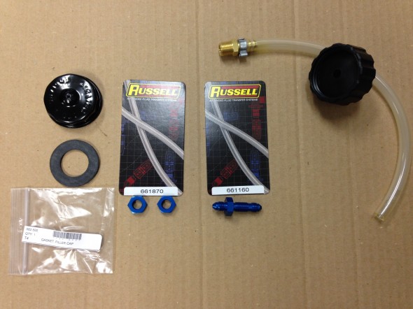
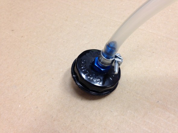
This master cylinder episode got my inspired to solve this little problem. I ordered another master cylinder reservoir cap and seal from Moss Motors. Part numbers 596-210 and 582-500. I then went on a search for a 1/4 brass fitting to install in the cap. The fitting was easy to find but after trying two automotive parts stores, a “they have it all” hardware store and a large plumbing supplier I gave up on finding a nut with the proper pipe thread! Finally, at a local fabrication shop I found these Russell fittings and they worked perfectly. The hose and cap #1100 to the right in the image below were supplied with the Motive Bleeder. I just disconnected the hose from the cap that did not fit.

Reservoir Cap Modification for Motive Bleeder

Reservoir Cap Modification for Motive Bleeder

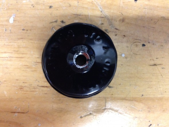
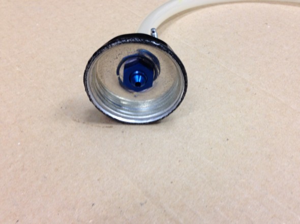
I then drilled a hole in the center of the Healey reservoir cap to tightly fit the Russell hardware. This required flattening the center of the cap which is raised on its top and bottom. Flattening the top is easier to do AFTER the hole is drilled in the top.

Drilled Hole in Cap

Drilled Hole in Cap 

The Russell fitting was then pushed/screwed through the cap and the nut was tightened on the reverse side.

Russell Fitting Secured in Cap

Russell Fitting Secured in Cap

Russell Fitting Secured in Cap

Russell Fitting Secured in Cap

To help ensure the fitting would be air tight, I then smeared a fairly heavy coating of Clear RTV Silicone around the fitting and nut in the reservoir cap. Finally the rubber seal provided by Moss Motors was inserted into the inside of the cap.

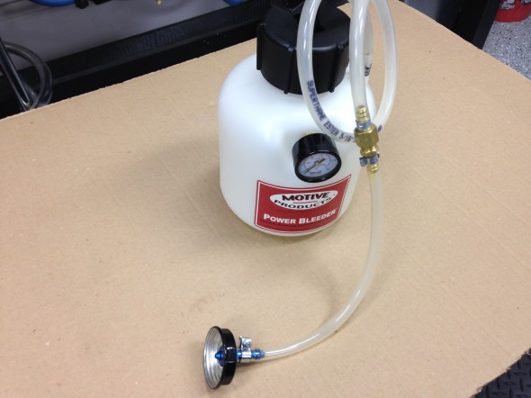
The new custom hose extension can then be attached to the pump hose and we are then ready to use the Motive Bleeder on a Big Healey.

Healey Custom Extension Connected to the Motive Power Bleeder

Healey Custom Extension Connected to the Motive Power Bleeder


June 12, 2014 – 

Conclave 2014 is to be held at the Homestead Resort, only two hours away from home. Judith and I will attend an plan to drive The Bloody Beast to the event. The car is generally in good condition, only needing a few things tended to before driving to Hot Springs, VA for the event.

  • Inspected and replaced the spark plugs, NGK BP6Es – stock number 7333.
  • Installed a new silicone rocker cover gasket, glued to the cover with permatex high temp red RTV silicone gasket maker. I then used Hylomar Advanced Formulation sealer (blue) between the gasket and the head. This work seemed to be effective in eliminating previous cover leaks. I have had problems with the gasket leaking with my cast alloy cover from Cape International. So, I will try this one from Gasket Innovations.http://www.gasketinnovations.com/index.php/gasket-innovations/product/110-gah-al6 
  • Polished the aluminum rocker cover and carb dashpots.
  • Repaired a bent exhaust hanger and leak.
  • Adjusted the adjustable steering wheel. The wheel had gradually moved toward the driver in an uncomfortable position. I was able to free the boss with channel locks and push the wheel to the dash fascia.
  • Removed each wire wheel and tire and polished all chrome and stainless steel. Approximately 1 1/2 hours per wheel.
  • Tightened the nuts on the rear tie down hooks. Both had become loose.
  • Checked all key fasteners to make sure they were secure: motor mounts, shocks, suspensions, propshaft and etc.
  • Washed the entire car, polished and waxed a few places.
  • Touched up paint in a few areas.
  • Cleaned all leather and vinyl surfaces and treated with Lexol.
  • Vacuumed carpets.
  • Polished chrome trim and cleaned windscreen and mirrors.

October 5, 2013 – 

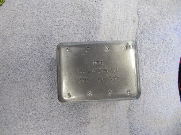
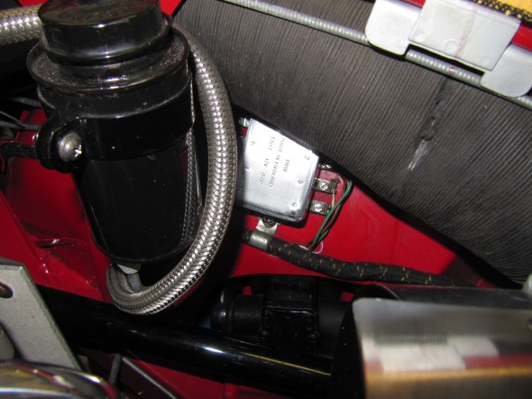
I was doing a little engine bay wipe down after having the Bloody Beast on a little road rally in Northern Virginia when I noticed that the surface of the light relay box mounted on the left front inner wing had deteriorated in appearance. I should have put a clear coat on the zinc when the cover was new, but did not think about it at the time. Any way, I removed the cover, sanded and polished it the best I could and then clear coated it before re-installation. Back to looking good once again.

Light Relay Box Cover Clear Coated

Light Relay Box Cover Clear Coated

Clear Coated Relay Box In Place

Clear Coated Relay Box In Place

May 24, 2013 – 1,580 miles

  • Removed the itg air filter, cleaned it and sprayed it with dust retention spray.
  • Replaced the purolator fuel filter just in front of the carbs with a new one.
  • Replaced the thermostat with a 195 degree unit and added a new gasket.
  • Changed the oil (20W-50), 6.4 quarts.
  • Installed new K&N oil filter – HP.2009
  • Greased all grease fittings.
  • Cleaned the underside of the car including wheel wells.
  • Touched-up paint in a few places.
  • Checked tire pressures.

Hub Nuts

I had some problems with loosening hub nuts on the rear hubs and upon closer examination discovered that the proper Healey hub nuts do not fit the hub stud opening as they should. My conclusion is that the reproduced Healey hubs mimic the angle of more contemporary hub nuts. Dorman  #611-014 hub nuts fit much better than the original nuts.

A New (And Proper) Master Cylinder

Although I had converted the front drum brakes to disc brakes not long after purchasing the Bugeye, I had not been able to find the proper 3/4” piston version that would have been used on the 1098 cars. My dad was able to source one from California during the previous winter, and in early August he installed it. He ordered the new master cylinder from Gerard Chateauvieux at Gerard’s Garage http://www.gerardsgarage.com Both the clutch and the brake master bores are 3/4″. The push rods are also shorter than the originals. More information is available from theses two pdf files:

Disc Brake Upgrade

BrakeCylinder.com– Midget Sprite Spridget Master Cylinders Disc Brake Upgrade

After bleeding the brakes and clutch we did end up with improved brake pedal feel and stopping power. He removed the entire pedal box, installed the new master and then re-installed the pedal box.

Master Cylinder

Master Cylinder

Bugeye Brakes Improvement

We have never been very happy with the brakes on the Bugeye. We installed front disc brakes but the pedal travel was way too much and the master cylinder always seemed to leak slightly. We were going to replace the master cylinder with the correct one for the 1098 car, but others suggested that the original 948 MC would work fine if everything else was working properly. Having the rear brakes adjusted properly and using aeroquip stainless steel brake lines were the primary suggestions for brake improvement.

We installed the stainless brake lines, and fitted new green stuff disc brake pads in the front, with new shims also. Purchased and installed new copper alloy brake lines throughout the car. Paul Asgeirsson was a big help on the proper process for adjusting the rear brakes.

Put the springs on the brake shoes from the back plate side BEFORE putting in the adjuster. Lots easier.

To put in the adjusters with the springs in place, just pry down the bottom shoe away from the wheel cylinder with a screwdriver.

Disconnect the parking brake cable from the cylinder brake arm.

Put the drum on over the shoes and put on the 2 drum holding screws.  These originally are pozi-drive screws and the phillips head screwdriver just chews them up.  Get some new ones that are phillips head.  They are 1/4 X 28 X 3/4″  flat head machine screws.  Readily available.

Now adjust the brakes up as tight as you can.  Press on the brake pedal pretty hard to seat the shoes.  Check the shoe adjustment by rotating the drum if you can.  If you can tighten up the adjuster nice and snug and back off one click.  Do both sides this way.  Should be able to rotate the drum OK, but typically not freely.

Hook up the parking brake clevis.  If it’s too short, loosen the adjuster inside the car.  5/8″ deep socket and hold the cable with a 1/4″ wrench on the flat spot.  Loosen until you can hook up the clevis.  Do both sides this way.

Now you need to final adjust the parking brake.  Take up the slack on both cables until they are just beginning to affect the rear brakes.  Make both cables equal tension.  Easy to check when you pull on the handle like you are parking the car.

Now the parking brake handle should only go up about 15 to 20 degrees.  Now this is important.  Never change the adjustment inside the car again until you reline the rear brakes again.

As the brakes wear, the handle will come up to maybe 45 degrees or so. That’s a signal to readjust the rear brakes.  When you do that, the park brake handle will only pull up 15 or 20 degrees again.

Paul also provided some brake adjusters for the rear drums that were in good shape and we used those. New brake shoes were also installed. Speed bleeders were used on the front calipers and the rear wheel cylinders. While working on the rear axle it seemed that the time was right to add new seals and gaskets.

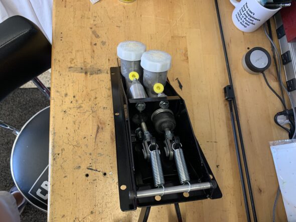
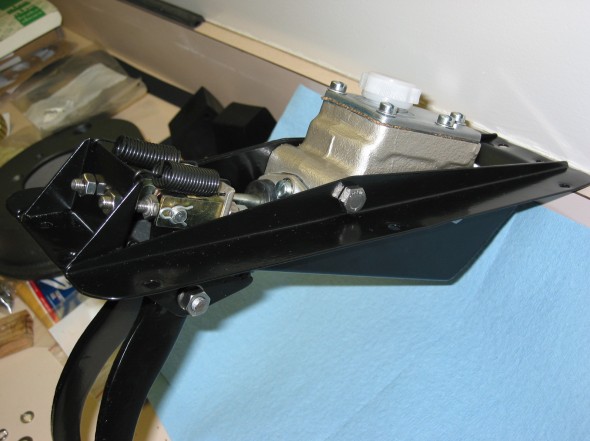
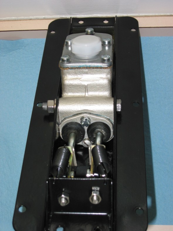
The old pedal box was a mess from leaky brake fluid so the box was pulled, cleaned up and powder coated for a more permanent finish. New gaskets were added to the master cylinder along with new push rods, clevis pins and etc. Also added new aluminum racing pedals to the brake and clutch pedals.

Finally, the system was bled and all the hard work was worthwhile!! Improved brake pedal and now we eagerly await actually putting the car on the road.

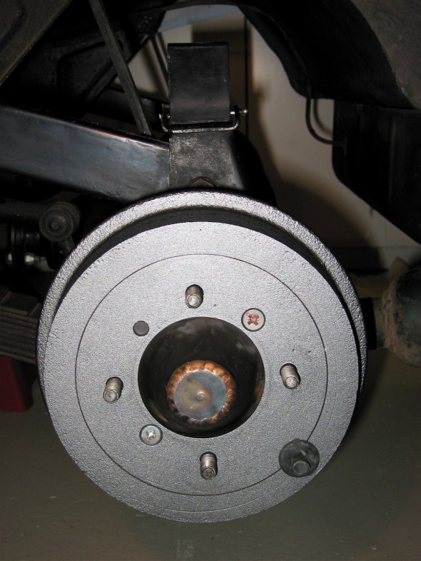
Powder Coated Drums

Powder Coated Drums

Ugly Pedal Box

Ugly Pedal Box

Powder Coated Box

Powder Coated Box

Pedal Box Restored

Pedal Box Restored