
Maintenance
October, 2014 –
Returning home from the Shenandoah Valley British Car Club show in Waynesboro, VA I noticed that the clutch pedal was slippery. Sure enough the seals in the master cylinder failed and I had some nasty brake fluid leaking from the cylinder. I removed both the brake and clutch masters figuring that I might as well rebuild them both at the same time. Both were brand new when installed in the car, so other than cleaning the bores I did not bother with a full rebuild including honing or lining the bores. I have fewer than 12,000 miles on the originals, but it has been five or six years and who know how long they were on the shelf before I installed them?
Both of my masters were 5/8″ bores and I decided to purchase a new 3/4″ bore for the brake system. Ordered one from British Parts Northwest.
In preparing to bench bleed the two masters I decided to purchase a little “HELP” kit from Summit Racing for all of $6.00. I did substitute clear hose for the black vinyl so that I could observe the air bubbles flowing to the fluid reservoir. The Healey master cylinders use the 3/8″ – 24 and the 7/16″ – 20 fittings, but many others are supplied in the kit.

Dorman Bench Bleeder Kit
Steve Gerow on the British Car Forum recommended “pulling” the air from the brake calipers rather than pushing the fluid from the reservoir:
“This bleeding syringe worked a charm, obviating the need for bench-bleeding. My Healey-neighbor Dennis Williams suggested packing the area around the nipple with grease to prevent air leakage. You just pull the air out of the system until you’ve got clear, bubble-free juice in the syringe. Keep an eye on the reservoir, of course.”
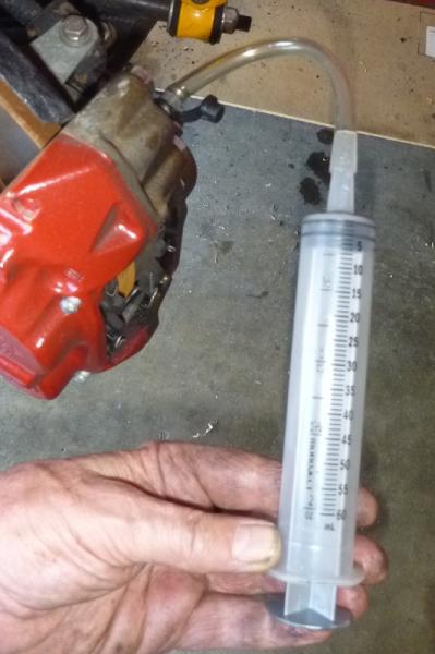
Cardone Brake Bleeding Syringe
Steve often comes up with the innovative ways of approaching maintenance issues so I thought I would give it a try. These are the directions that came with the syringe:
Cardone 10-5000MCB Master Cylinder Bleeder Tool Directions
I was overdue for a complete brake fluid flush so I pumped out all of the old stuff while I was at it.
Motive Power Bleeder
I have had a Motive Power Bleeder http://www.motiveproducts.com for several years and never used it. I ordered the special reservoir cap specified for the Healey – Part number 1100 I believe. It did not fit!
This master cylinder episode got my inspired to solve this little problem. I ordered another master cylinder reservoir cap and seal from Moss Motors. Part numbers 596-210 and 582-500. I then went on a search for a 1/4 brass fitting to install in the cap. The fitting was easy to find but after trying two automotive parts stores, a “they have it all” hardware store and a large plumbing supplier I gave up on finding a nut with the proper pipe thread! Finally, at a local fabrication shop I found these Russell fittings and they worked perfectly. The hose and cap #1100 to the right in the image below were supplied with the Motive Bleeder. I just disconnected the hose from the cap that did not fit.
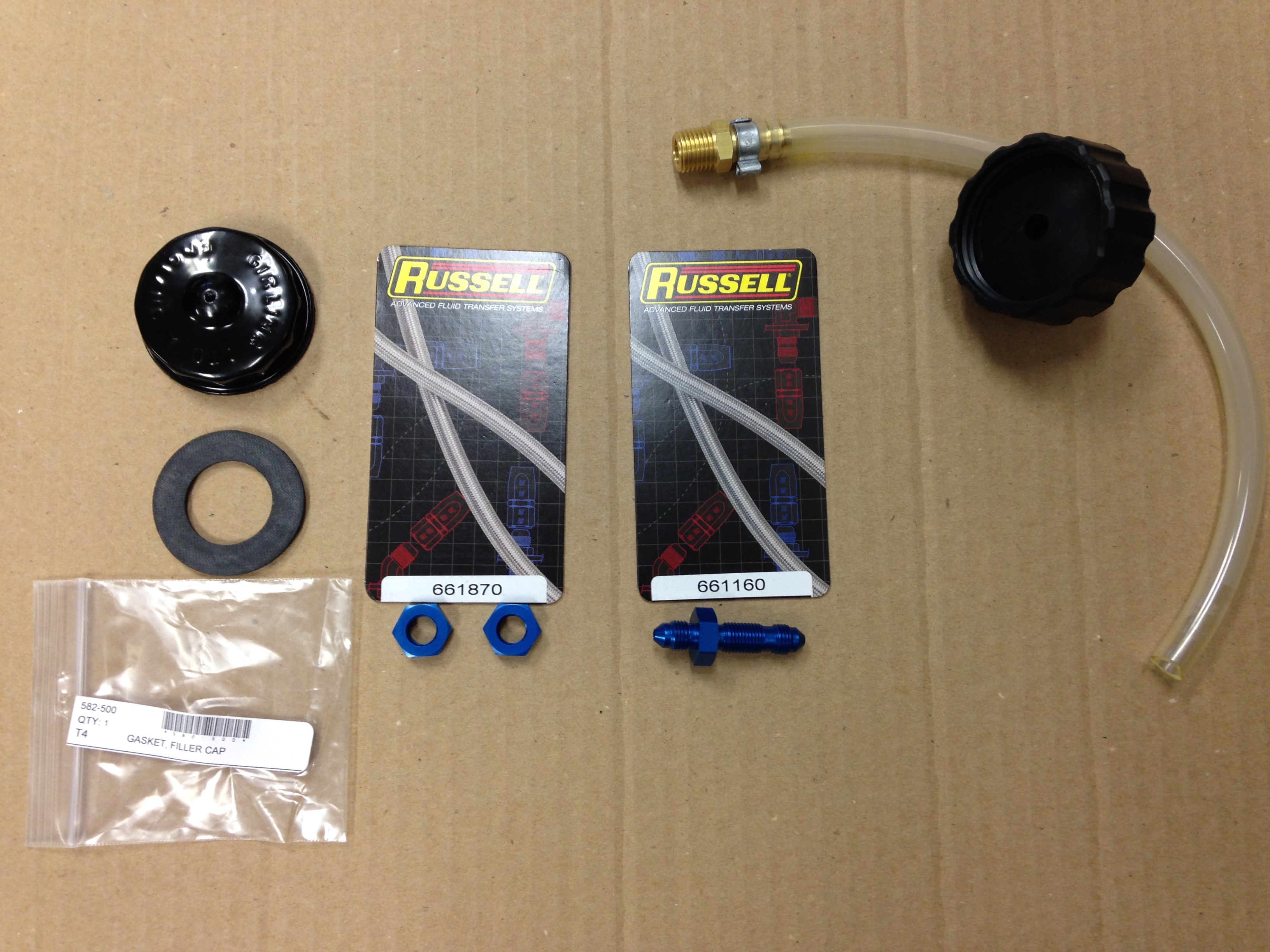
Reservoir Cap Modification for Motive Bleeder
I then drilled a hole in the center of the Healey reservoir cap to tightly fit the Russell hardware. This required flattening the center of the cap which is raised on its top and bottom. Flattening the top is easier to do AFTER the hole is drilled in the top.

Drilled Hole in Cap
The Russell fitting was then pushed/screwed through the cap and the nut was tightened on the reverse side.
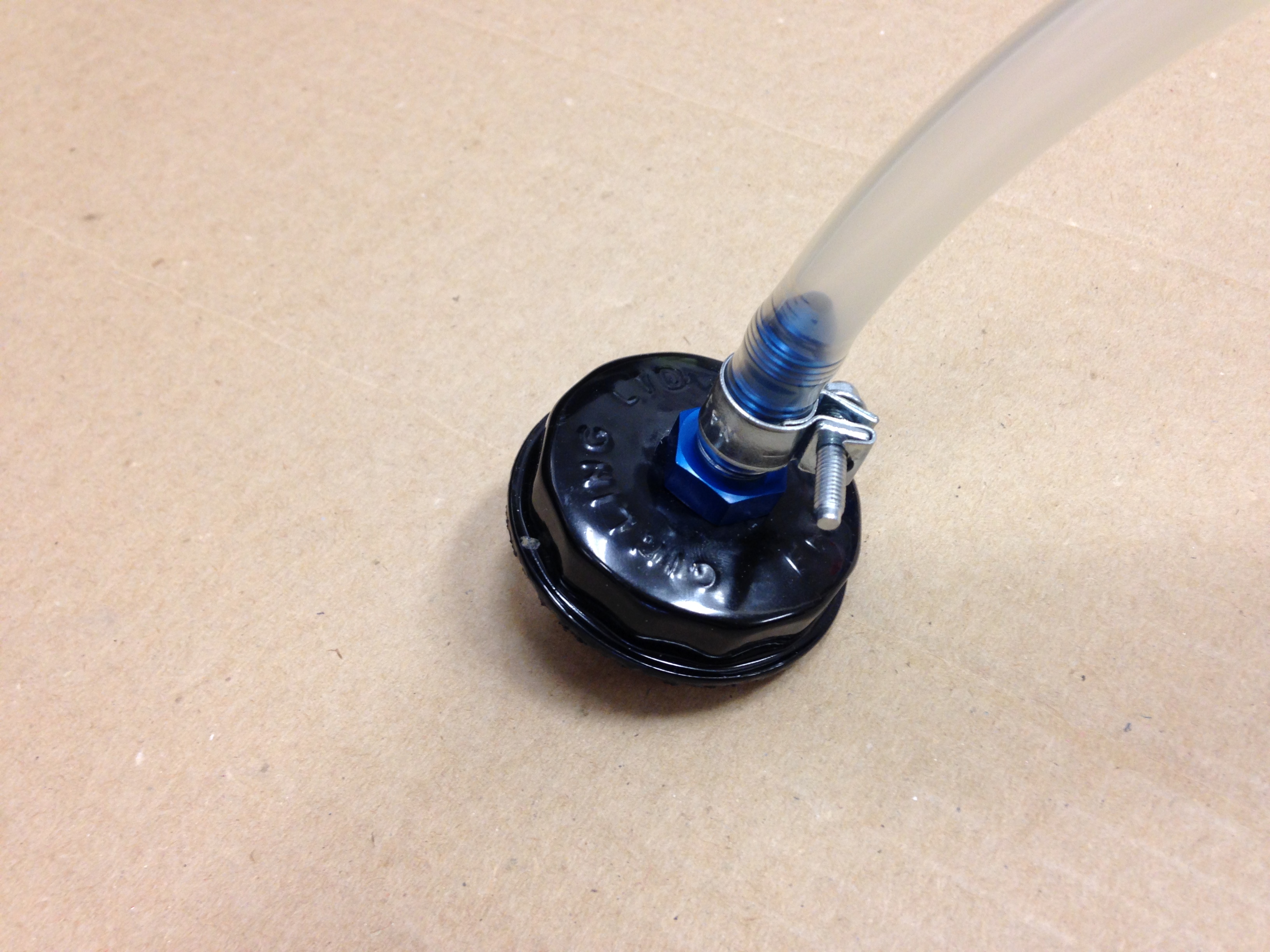
Russell Fitting Secured in Cap

Russell Fitting Secured in Cap
To help ensure the fitting would be air tight, I then smeared a fairly heavy coating of Clear RTV Silicone around the fitting and nut in the reservoir cap. Finally the rubber seal provided by Moss Motors was inserted into the inside of the cap.
The new custom hose extension can then be attached to the pump hose and we are then ready to use the Motive Bleeder on a Big Healey.
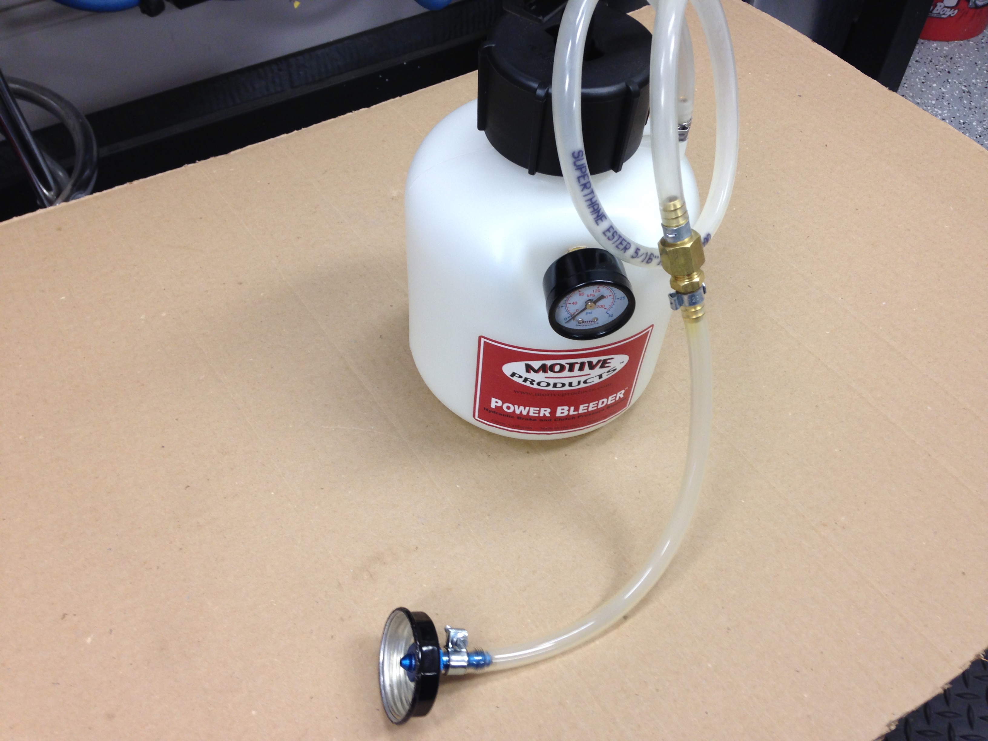
Healey Custom Extension Connected to the Motive Power Bleeder
June 12, 2014 –
Conclave 2014 is to be held at the Homestead Resort, only two hours away from home. Judith and I will attend an plan to drive The Bloody Beast to the event. The car is generally in good condition, only needing a few things tended to before driving to Hot Springs, VA for the event.
- Inspected and replaced the spark plugs, NGK BP6Es – stock number 7333.
- Installed a new silicone rocker cover gasket, glued to the cover with permatex high temp red RTV silicone gasket maker. I then used Hylomar Advanced Formulation sealer (blue) between the gasket and the head. This work seemed to be effective in eliminating previous cover leaks. I have had problems with the gasket leaking with my cast alloy cover from Cape International. So, I will try this one from Gasket Innovations.http://www.gasketinnovations.com/index.php/gasket-innovations/product/110-gah-al6
- Polished the aluminum rocker cover and carb dashpots.
- Repaired a bent exhaust hanger and leak.
- Adjusted the adjustable steering wheel. The wheel had gradually moved toward the driver in an uncomfortable position. I was able to free the boss with channel locks and push the wheel to the dash fascia.
- Removed each wire wheel and tire and polished all chrome and stainless steel. Approximately 1 1/2 hours per wheel.
- Tightened the nuts on the rear tie down hooks. Both had become loose.
- Checked all key fasteners to make sure they were secure: motor mounts, shocks, suspensions, propshaft and etc.
- Washed the entire car, polished and waxed a few places.
- Touched up paint in a few areas.
- Cleaned all leather and vinyl surfaces and treated with Lexol.
- Vacuumed carpets.
- Polished chrome trim and cleaned windscreen and mirrors.
October 5, 2013 –
I was doing a little engine bay wipe down after having the Bloody Beast on a little road rally in Northern Virginia when I noticed that the surface of the light relay box mounted on the left front inner wing had deteriorated in appearance. I should have put a clear coat on the zinc when the cover was new, but did not think about it at the time. Any way, I removed the cover, sanded and polished it the best I could and then clear coated it before re-installation. Back to looking good once again.
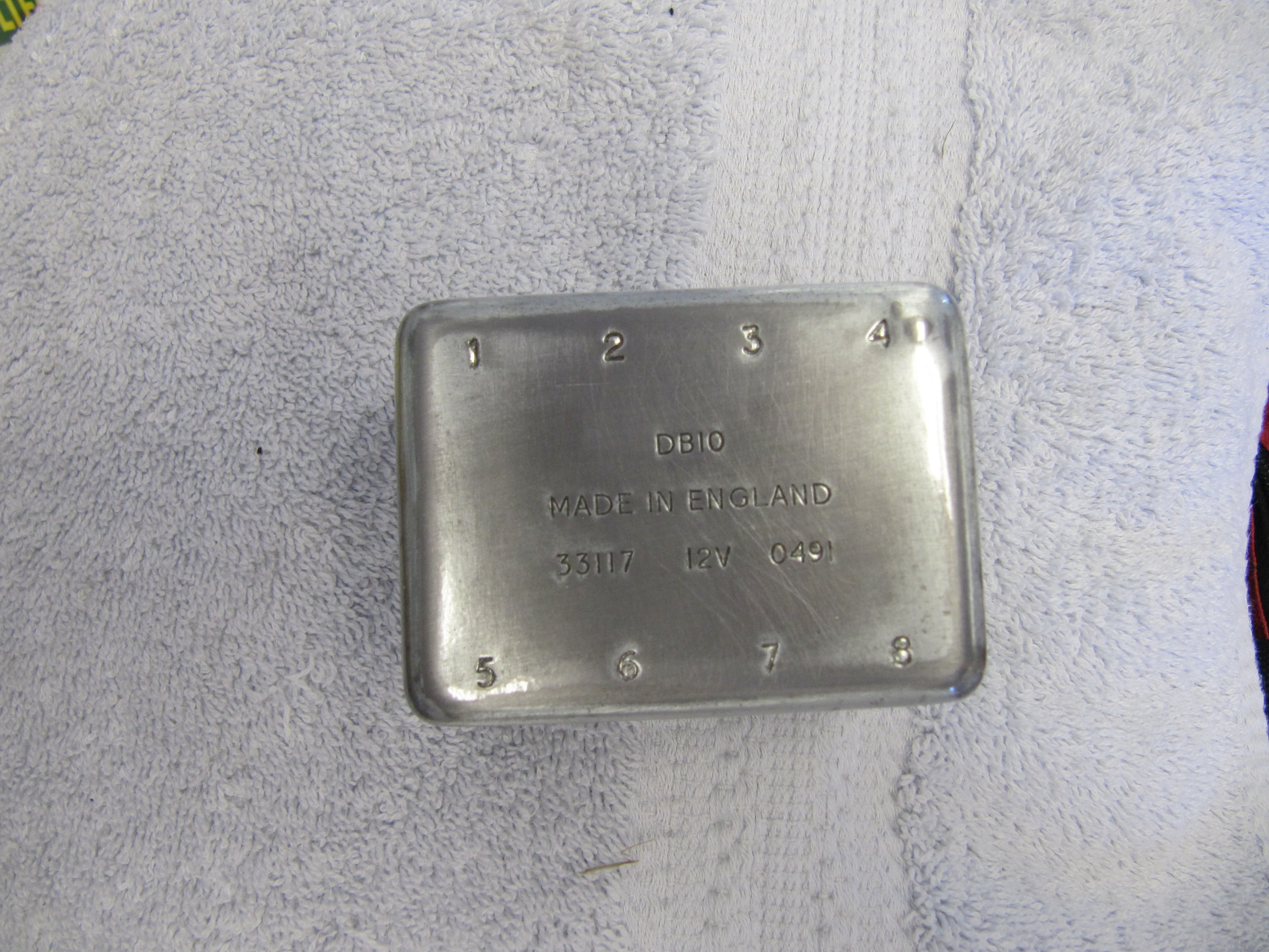
Light Relay Box Cover Clear Coated
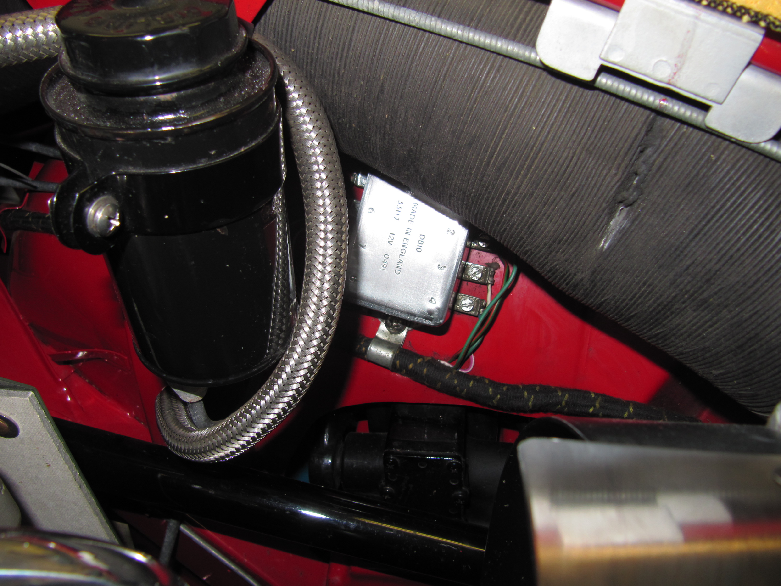
Clear Coated Relay Box In Place
May 24, 2013 – 1,580 miles
- Removed the itg air filter, cleaned it and sprayed it with dust retention spray.
- Replaced the purolator fuel filter just in front of the carbs with a new one.
- Replaced the thermostat with a 195 degree unit and added a new gasket.
- Changed the oil (20W-50), 6.4 quarts.
- Installed new K&N oil filter – HP.2009
- Greased all grease fittings.
- Cleaned the underside of the car including wheel wells.
- Touched-up paint in a few places.
- Checked tire pressures.
Hub Nuts
I had some problems with loosening hub nuts on the rear hubs and upon closer examination discovered that the proper Healey hub nuts do not fit the hub stud opening as they should. My conclusion is that the reproduced Healey hubs mimic the angle of more contemporary hub nuts. Dorman #611-014 hub nuts fit much better than the original nuts.