Three Point Retractable Harnesses

We had three point harnesses in the Bugeye before restoration; however, the belts were always getting caught in the doors and could cause paint damage. This time around, we decided to install three point retractable belts. We purchased these from Bugeyeguys. https://bugeyeguyparts.com/products/3-point-inertia-seat-belts They are a little on the burgundy side but we think this color will go better with the red in the car than a bright red would.

We fit them before paint because installation required drilling a number of holes in the chassis. The Bugeye Restoration Shoulder Harness Video shows the installation process. https://vimeo.com/985658212/a3227b71de?share=copy

Custom Brake Switch

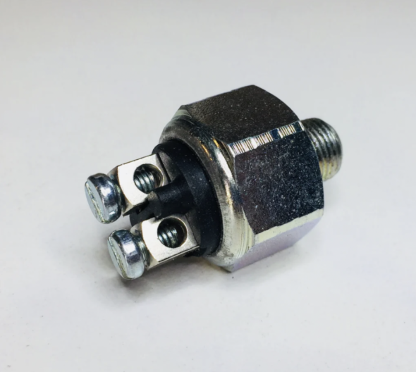
Recently produced hydraulic pressure switches for brake light activation are often faulty and/or don’t last long.

Hydraulic Brake Light Switch

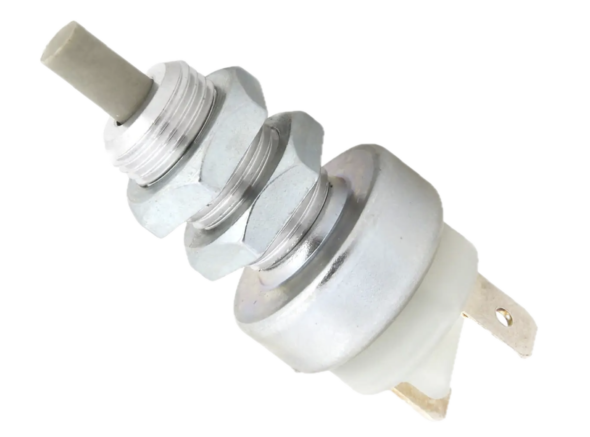
We decided to use an electronic pedal activated pressure switch as a complement to the hydraulic switch. We sourced the switch from Moss Motors, part number 542-371.

Lucas-type Brake Light Switch

We have modified the wiring harness to accommodate both switches. Trevor Fawcett, in the U.K., fabricated a simple bracket to hold a Lucas pedal switch and we used that as a model for our own bracket – similar, but not the same.

Trevor’s Brake Switch and Bracket

Trevor’s Brake Switch and Bracket Mock-up

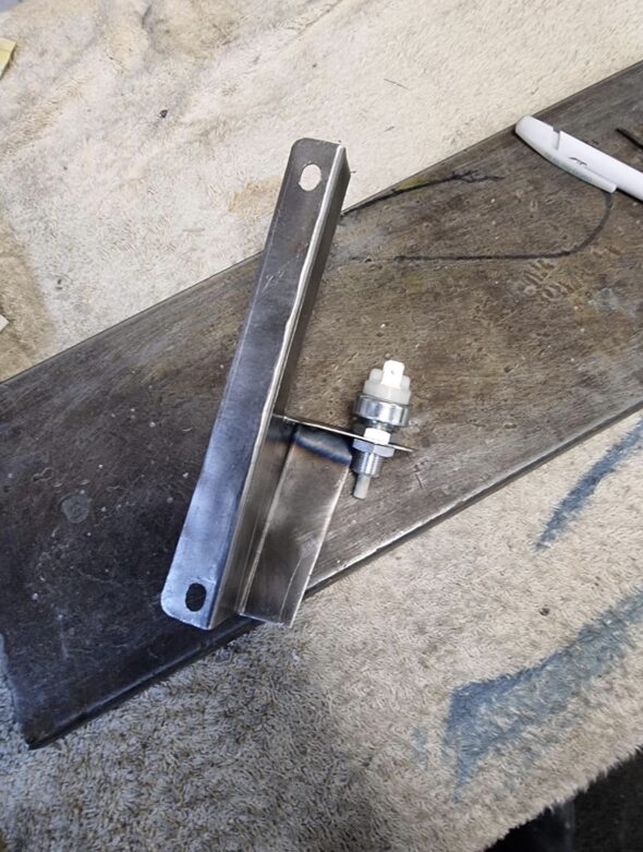
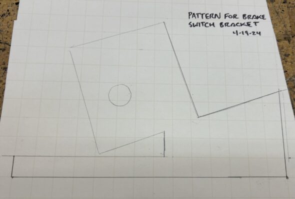
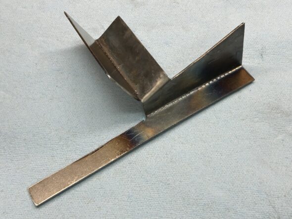
This was our starting pattern (it was slightly modified later), and our bracket after a little bending of a single flat piece of steel in the vice.

Brake Switch Bracket Pattern

Brake Switch Bracket Fabricated

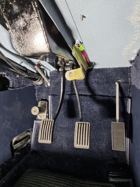
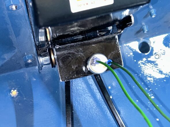
After drilling holes for mounting the bracket to two of the 1/4″ – 28 x 1″ bolts holding the pedal box to the chassis and drilling a 1/2″ hole for the switch we we ready to mount the assembly to the car. Following trial fitting we trimmed a bit here and there, rounded the sharp corners and painted it black.

Pedal Brake Bracket & Switch Mounted to the Pedal Box

Finally, we connected two trial wires to the switch’s spade connectors and tested the sensitivity of the switch with a test light. The results are depicted in the short Bugeye Restoration Video Episode Seventy-three below:

https://vimeo.com/982091053/002655f0fb?share=copy


Custom Master Cylinder, Pedal Box and Hydraulics

Master Cylinders/Pedal Box

We had been using the original tandem master cylinder originally designed for the bugeye; however, it was a master cylinder sourced from Gerard Chateauvieux of Gerard’s Garage that was modified to incorporate 3/4″ bore pistons for the brakes and the clutch.

Twin Chamber 3/4″ Master Cylinder

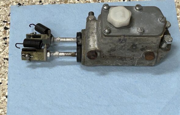
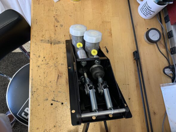
Sebring Sprites used a custom pedal box with two offset Girling master cylinders with their own fluid reservoirs. We purchased a replica of the Sebring Pedal Box from Brookfab in the U.K. https://brookfab.co.uk/

We were quite pleased with the Brookfab assembly including the master cylinders, push rods and springs – very professional job.

Brookfab Pedal Box with Girling Master Cylinders

Brookfab Pedal Box

Brake Pipes and Hoses

All new cunifer copper alloy brake pipes with stainless fittings were formed and installed on the car for the 2024 restoration. In addition, Goodridge Stainless Braided (black) were also installed on the car. Both can be seen in the image below:

Cunifer Brake Pipes and New Fittings

Cunifer Brake Pipes and Goodridge Hoses

Brake Fluid

We have decided that because all of the brake system and clutch system are totally new we will use Dot 5 silicone brake fluid in the Bugeye.

Front Disc Brake Conversion

We bought the Bugeye in 1998 and shortly thereafter the car was taken to Grand Touring Classics, Inc in Stanarsville, VA for a safety inspection and a conversion to front disc brakes. Garland Gentry and his assistant took care of collecting the needed parts from a post 1964 Midget and installing them on the car. After some period of time we changed out the 7/8″ master cylinder for a 3/4″ which worked much better.

Of course, it is not as simple as just switching out the brakes. it is also necessary to install new stub axles and king pins, dust tubes and springs, hubs, back plates, calipers, hose brackets, rotors, pads with pad retaining plates with clips, new hoses with banjo bolts and copper washers. For the complete restoration of the car in 2024 all of the front brake components were updated and/or replaced. Parts were sourced from A.H. Spares and Moss Motors.

The front brakes, steering and suspension are integrated in assembly. Details of all of these  mechanicals are detailed in other posts regarding these subjects. The build up of the front hub assemblies and brakes ,may be found in this post: https://valvechatter.com/?p=13792   A video showing the assembly is included in the post.

Rear Drum Brake Upgrade

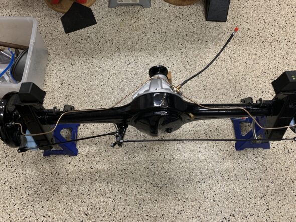
A common upgrade to the braking system for Bugeyes is the replacement of the rear  drum brakes which use a single action 7/8″ rear cylinder with later MG Midget rear brakes using a larger 3/4″ dual action rear cylinder. We were able to acquire the later backing plates, wheel cylinders, and brake shoes with springs, and handbrake levers from Gerard Chateauvieux of Gerard’s Garage. He indicated that the donor car was in the 1968-72 time frame.

Rear Brake Components

LH Rear Brake Assembly with Shoes and Cylinder

LH Rear brake assembly

The conversion also required using new crossbars or rods for the handbrake system as the original Bugeye crossbars are not shaped properly for the later brakes. These were purchased from Mini-Mania.

Adjustable Handbrake Crossbars

We did have problems with the drums rubbing against the backplates and had to grind away some material from the hub edge to avoid the conflict. 

More information about the build-up of the rear brake conversion including an assembly video that details the problems we encountered may be found in two other posts: “Rear Drum Brake Upgrade”  https://valvechatter.com/?p=13399 and “Bugeye Rear Axle Assembly” https://valvechatter.com/?p=13569 in the restoration series. These posts and their included videos show the mounting of the rear hubs and brake assemblies to the rear axle.

Redundant Electric Fuel Pumps

The Bugeye began life with a 948 cc four cylinder motor that had a mechanical fuel pump mounted to the engine block. We converted to an electronic SU negative ground 12 volt fuel pump years ago and it was mounted in the engine bay. Then we mounted the pump in the rear of the car as outlined in an earlier post: https://valvechatter.com/?p=13599

SU electronic fuel pump negative earth

The SU pump was sourced from AH Spares in the UK. After acquiring the Michigan body shell we decided to modify the fuel delivery system yet again to incorporate a redundant electronic pump to have a ready back up in the case of a pump failure. The back up pump was sourced from Pegasus Racing and it is a Facet Cylindrical pump rated at 2.75-4 psi.

Facet Cylindrical 2.75-4 PSI Negative earth electronic fuel pump

The two pumps are installed in series and will be wired with a toggle switch permitting the selection of either pump or no pump at all – an effective theft deterrent. Nut serts (1/4″-20) were installed in the rear bulkhead to serve as mounting points for the rubber isolators, also purchased from Pegasus, that fit between the bulkhead and the pumps. 

A new stainless steel pre-bent fuel pipe was purchased from Summit Racing, modified to accommodate the new pump setup and installed in the car.

Bugeye Interior Personalizations

We have introduced a number of modifications in the interior to suit our interests. These are listed in no particular order below:

Gauges – Speedometer and Tachometer

The right hand drive connector for the speedometer cable on the Rivergate five speed conversion never worked well. Once the cable came loose and a second time the cable broke.

Rivergate Speedo Cable Adapter

Now seemed to be the perfect time to convert to the GPS speedometer sold by Bugeye Guy.

The unit is made by Speedhut instruments and apparently David at Bugeyeguy.com has a custom face made for the unit to look similar to the original Sprite gauge face. Details about installation including the wiring may be found in another post “A New Electrical System.”: https://valvechatter.com/?p=13986

The speedometer uses a gps sensor which routed between the driver’s door and the dash trim and is secured to the top of the dash with a magnetized plate.

Bugeye Guy GPS Speedometer

Bugeye Guy Speedo GPS Sensor

We liked the speedometer so much that we ordered the matching tachometer too!

Speedhut tachometer

Many of the electrical connections for the tachometer take advantage of the wiring loom provided with the speedo so that the tachometer can piggy-back for shorter wiring runs. Really happy with both of these upgrades. At first glance, the new instruments do look very much like the originals.

Hazard Switch and Lights

Of course, the Bugeye did not come equipped with hazard or caution lights. However, in today’s world and particularly with such a small car, hazard lights are really essential. The Classic Technologies relay/fuse box incorporates a hazard flasher relay system. We purchased a Lucas 155SA hazard switch to activate the system.

Lucas Hazard Switch

The switch is a push/pull type and incorporates a flashing warning light in the body of the switch. The switch will be added to the dash panel we built and is installed behind the dash.

The Lucas 155SA hazard switch was used in many British cars, and apparently the one we ordered was used in the 1974-75 triumph TR6 and the 1973-77 Triumph Spitfire. Details about installation including the wiring may be found in another post “A New Electrical System.”: https://valvechatter.com/?p=13986

Variable Speed Wiper Controller

Some years ago Ed Esslinger authored an article on a Sunbeam Tiger web site about a kit he put together to provide unlimited variable control of the speed of the Lucas wiper motor. We tried one of his kits on the Big Healey and liked it. Great for handling mist and light rain. Unfortunately it doesn’t make the wipers go any faster! 

We installed the control knob for the variable speed rheostat on the vertical panel we made and installed behind the dash. We took advantage of the blanking bolt nuts intended for the steering column bracket in a RH drive car as a location for mounting the  controller electronics. No holes were drilled in the chassis. Details about installation including the wiring may be found in another post “A New Electrical System.”: https://valvechatter.com/?p=13986

LED interior gauge lamps

All of the lights were converted from the original incandescent bulbs to LEDs sourced from Moss Motors.

LED Interior footwell and boot courtesy lights

LED interior footwell, map and boot courtesy lights operate remotely by a key fob or manually with a toggle switch on the panel behind the dash.  We ordered the RF Relay and key fob from Amazon. DieseRC 433Mhz Universal Wireless Remote Control Switch DC 12V 1CH RF Relay Receiver Module with 1 Transmitter, EV1527 Learning Code Remote Switch. Details about installation including the wiring may be found in another post “A New Electrical System.”: https://valvechatter.com/?p=13986

RF Courtesy Light Controller

The boot has two aimable LED lights. Each one is mounted on the LH and RH rear interior quarter panels. These lights were sourced from SuperBright LEDS. 

Boot LED Light


In the front footwells we also installed LED lights sourced from Better Car Lighting in the UK. 

Footwell Lights and Brackets

Turn Indicator Warning Buzzer

The turn indicator switch in the Bugeye is not self-canceling. While there is a warning lamp on the dash located between the speedometer and the tachometer, it is often not sufficiently bright to let the driver know to turn the switch to the off position. We installed a little buzzer sourced from Radio Shack to provide an audible alert when the flashers are turned on. 

Modified Windscreen Washer Pump (plunger) 

The Bugeye came equipped with a windscreen washer system that was activated by pushing a plunger mounted in the dash. The pressure created by pushing the plunger moved the cleaning fluid out to the windscreen. The process worked well enough, but when the Big Healey was restored we became aware of Stu Brennan, an owner of a Sunbeam Tiger, who had converted his hand activated pump windscreen washer to an electric washer. Stu’s idea was to put an electric momentary micro switch inside the aluminum pump canister thereby eliminating the need to install an additional switch somewhere. Since the washer in the Tiger is the same as the one in both the Big Healey and the Bugeye we decided to give it a try.

Two items needed to be purchased for the conversion. An electric pump typically used on later Sprites was ordered from Moss Motors.  A Home Depot switch was purchased, Gardner-Bender, Push Button, GSW-22, SPST always-off. Details about installation including the wiring may be found in another post “A New Electrical System.”: https://valvechatter.com/?p=13986

Washer Pump Parts

Under Dash Parcel Tray

Later Sprites and MG Midgets had a parcel shelf mounted under the dash on the passenger side of the car. We decided that it might make sense to add one to the Bugeye as well because there just isn’t much space for storing small items. The shelf was originally made from some type of fiberboard. We located a fellow in the U.K. who makes the shelves out of aluminum and for an extra commission will add the front rubber cushion to the shelf too. All at a very reasonable price.https://www.ebay.com/sch/i.html?item=116168223491&rt=nc&_trksid=p4429486.m3561.l161211&_ssn=bicycle55cps

This is an image of the shelf sans the rubber cushion. All of the mounting holes are incorporated. We will cover the shelf in red vinyl to match the interior.

Aluminum Parcel Shelf


Seat Belt Harnesses

Upgrading to shoulder harnesses was a must, but unlike the belts we had in the car previously, we decided on retractable units this time around. We ordered our belts from BugeyeGuys.

Red Retractable Seat Belts

While we generally try to do everything we can to avoid drilling new holes in the Bugeye sheet metal, it is required for this installation. Four holes in the interior floor and two holes in the rear wheel wells.

Seat belt mounting holes

Shoulder Harness Retractor Holes


This is a brief video showing the installed belts:

https://vimeo.com/942791115/4a83c628a8?share=copy

cccccc

Carburetor Swap to HIF 44

The Bugeye originally had 1 1/4″ twin SU carburetors. We upgraded to twin 1 1/2″ HS2 carbs shortly after purchasing the car. With the current restoration we are going to try a single 1 3/4″ HIF44 carb. We hope to attain equal performance without the need to balance twin carbs. The single HIF carb was routinely used on Minis with essentially the same engine. The HIF 44 is SU’s most modern carb of the period. The float bowl is integrated into the bottom of the carb body rather than a separate float bowl as with the HS2s. 

Using the HIF carb requires the use of an appropriate heat shield with integrated securing points for the throttle and choke cables. I ordered this one https://www.ebay.com/itm/163969687994  not only is it polished stainless, it also provides an angled extension under the bottom of the carb (where the float bowl is located) to provide a little extra heat protection. This is a very nice piece.

Modified stainless HIF 44 Heat Shield

 A custom intake manifold is also required on the Bugeye. Sourced from Maniflow in the UK. This manifold lowers the carb so that it will not foul against the bonnet.

Maniflow 1 3/4″ Intake Manifold Jet-Hot Coated

After purchasing the HIF44 we sent it to A.C. Dodd in the UK to have him modify it slightly. The biggest change was converting the unit from manifold vacuum to ported vacuum. Bugeye Restoration Video Episode Fifty-nine reviews the features of the HIF 44 and explains the modifications made to it by A.C. Dodd to prepare it for use in the Bugeye.

https://vimeo.com/924772088/d53a91b278?share=copy

Episode Fifty-nine includes the following content:

0:05 – HIF 44 carb documentation

0:45 – Applications of the HIF 44 carb in other cars

1:37 – HIF 44 carb needle

2:20 – Manifold and Ported vacuum

2:26 – HIF 44 Carb heat shield

2:32 – Maniflow intake manifold

2:50 – Choke cable retaining clip

3:23 – A.C. Dodd HIF 44 modifications

5:33 – HIF 44 Hose fitting legend

5:39 – HIF 44 Throttle and choke cable connections 

Setting up the HIF 44 for initial running is really quite simple. (more info to follow shortly!)

HIF 44 Carburetor (RH Side)

HIF 44 Carburetor (LH side)

Setting the fuel mixture is the first step. This is accomplished by turning the fuel mixture screw shown in the image above. The image below shows the proper level of the jet:

HIF 44 Proper Jet Height for Start-up

Turning the adjustment screw to the left will lean out the mixture by raising the jet thereby letting less fuel enter the manifold. Turning it to the right will enrich the mixture. This screw should only be adjusted to effect a change in the idle. It should not be adjusted  to improve the drivability of the car at speed.

The fast idle, or choke, is set by adjusting the fast idle screw against the cam. The images below show the proper setting. The fast idea screw is turned down until it just touches the throttle lever. Once in that position it can be turned down one full turn. A feeler gauge with .018 blades is then inserted between the fast idle screw and the throttle lever. The choke lever is then rotated to line up with the center of the throttle adjusting screw. This is achieved by turning the adjusting screw until it just touches the arrow.

HIF 44 Adjusting the Choke

A small spring clip is used to secure the choke cable end fitting to the heat shield choke bracket. It is a friction fit and is just pressed down over the end of the cable ferrule.

HIF 44 Choke Cable Clip

A two piece cable stop is used to secure the choke cable to the choke lever:

HIF 44 Choke Cable Stop

 We also decided to improve air flow into the carb by installing an aluminum stub stack sourced from M.E.D. Engineering in the UK.

MED Stub Stack

Their site describes the billet stub stack this way:

The MED aluminum stub stacks have been extensively tested on our 110 Superflow flow bench to optimise the elliptical radius on the stub stack. The result is improved air flow to the carburettor/throttle body and a proven increase in performance – on a wide range of different engines and rolling roads.

The stub stack is temporarily mounted in this photo. Eventually the K&N air filter back plate will be installed first with the stub stack mounted inside the filter assembly.

Stub stack temporary installation

Much of the tuning of the HIF 44 carb is accomplished through needle adjustment, spring choice and variations in damper oil weight. Our carb came with a BFY spring loaded needle. Upon initial running (but before we have connected an AFR gauge) the engine seemed to run well at higher rpm but lugged a bit at idle and required the use of the choke for longer than expected. We wondered if the BFY needle was the cause of insufficient fueling at idle, so we decided to try a BDL needle. 

The .100″ jet needles (the middle needle below) are measured in 16 increments:

Needle Metering Increments

The following chart depicts the difference between the BFY Needle and the BDL Needle. As can be seen, the needles are very similar. The only differences are in positions 2,3,4 and 5. This should leave us with a slightly richer condition at idle and maintain the same fuel condition in the higher rpm range. Hopefully we will not need as much choke this time. Additional running will tell us if we have improved our running at idle or not.

BFY and BDL Needle Comparison

Finally, we are using a K&N Cone-type air filter for the carburetor. We sourced this one from Moss Motors:

K&N Air Filter

K&N Filter Packaging


Powerspark Electronic Distributor

We previously used a Crane Fireball electronic ignition module in conjunction with the original Lucas 25D. We had the distributor rebuilt and recurved based on our engine modifications by Jeff Schlemmer at Advanced Distributor, However, after some research and discussion with A. C. Dodd, a U.K. “A series” engine tuner we decided to make a wholesale conversion to modern technology and purchased a Powerspark Lucas 45D Distributor. The Lucas 45D distributor replaced the 25D in 1975.

Powerspark manufactures the new distributor casting from an original Lucas model, so it visually appears like the original. The distributor is available in a number of variations. We selected a negative ground high energy model with Powerspark’s electronic ignition module with vacuum advance and top entry cap referred to as D5.

Powerspark 45D with Cap

The distributor is a variable dwell design and the electronic module is capable of three times the spark of their standard sport module. This unit uses a non-ballasted .8 ohms coil and is not suitable for use with copper leads so we have used Cobalt carbon leads sourced from Moss Motors.

This YouTube video by A.C. Dodd does a nice job of explaining the desirability of transitioning to a modern electronic ignition distributor:https://youtu.be/nHOQzi-Je1I?si=NehsJxJQ6vHdZg1Z

At the same time that A. C. Dodd was modifying our new HIF 44 carburetor, we had him recurve our Powerspark dizzy to suit the modifications made to our engine. The unit is now set to reach maximum advance at 3,800 rpm.

We also decided to go with the Viper dry resin high energy .8 ohm coil sold by Powerspark.

Viper Dry Resin High Energy .8 ohm Coil

Rear Differential Swap 4.22 to 3.9

A number of Bugeye owners have suggested switching the original 4.22 rear differential for a 3.9 differential from a later Sprite or Midget. We located a 3.9 in North Carolina. We had it checked out by Glenn’s MG in St. Petersburg. He installed a new pinion oil seal and set the pinion pre-load to factory specification. We cleaned up the pumpkin and painted it with silver caliper paint from POR-15. 

The Episode Eight video provides details on the 3.9 differential installation and background.

https://vimeo.com/769556695/420d4bfca6