February 12, 2005
Fitting Shrouds and Wings
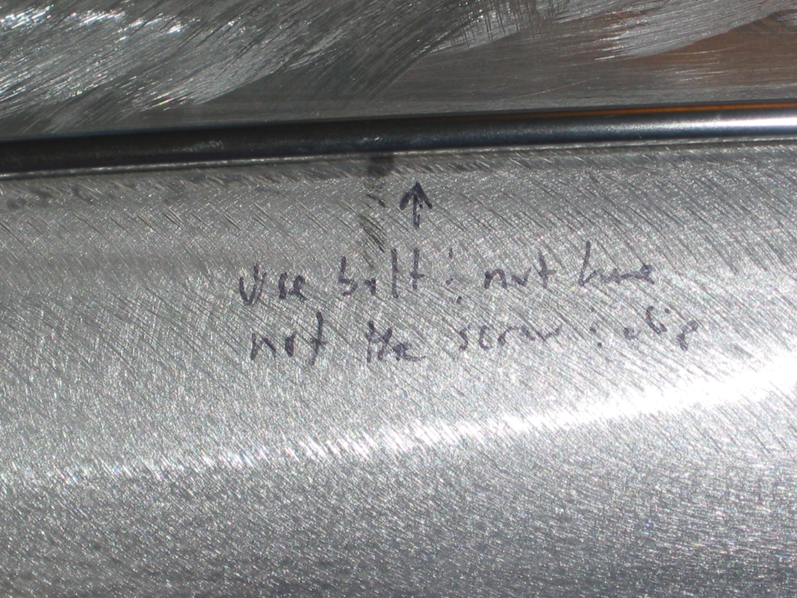
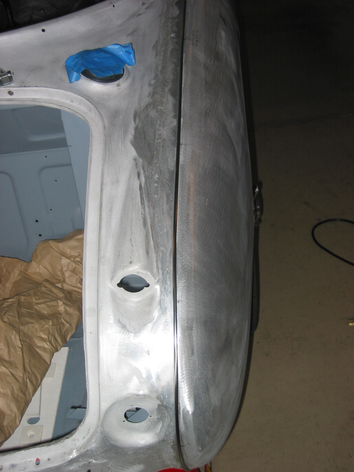
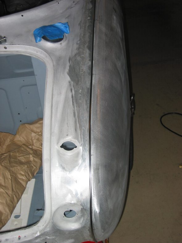
Rear Shroud –After removing all small components from the car I secured the shrouds and wings to the car to prepare it to go to Jeremy Turner for panel fitting and painting. To get the shroud and wings lined up properly, the rear shroud first needs to be riveted to the frame. There are a number of sheet metal screw holes in the superstructure and the shroud that Martin used to position the shroud, they are not needed for final installation.
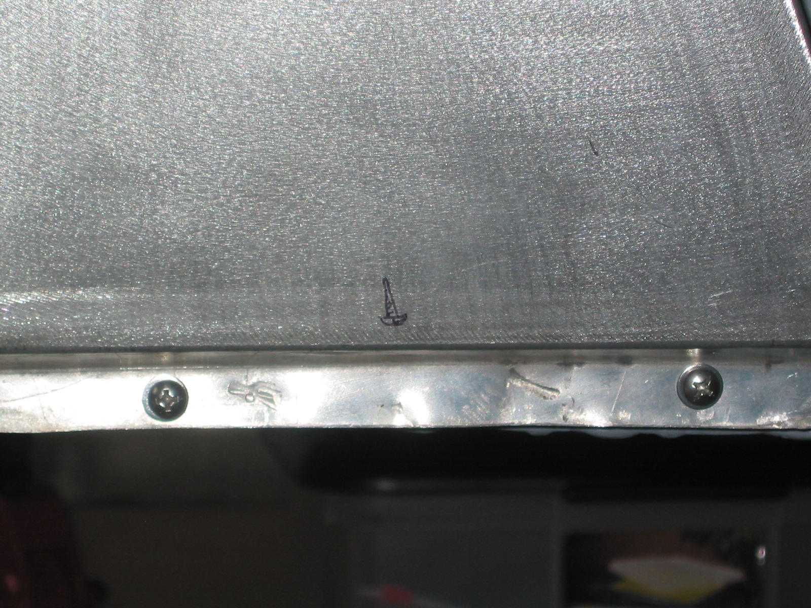
In addition to the rivets, there are six #10 –32 x 1/2” flat head screws and nuts inside the top rear lip of the boot lid channel. Four of the screws attach through the two steel metal clips that provide support for the boot lid hinges.
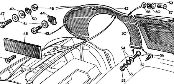
rear fender fasteners
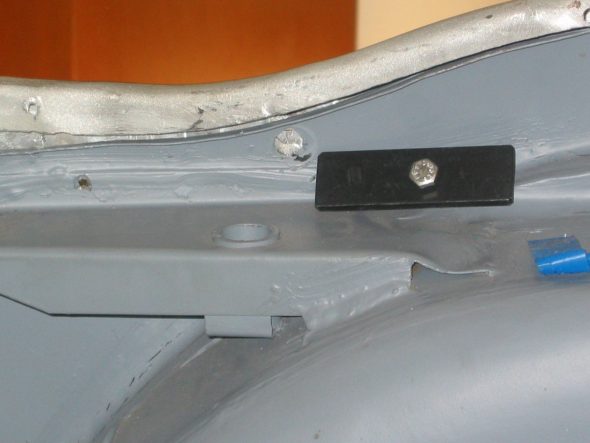
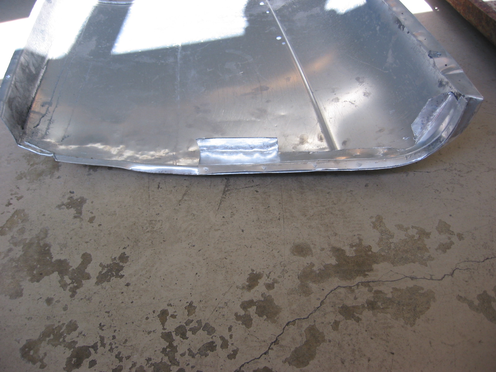
Rear wing securing plate 1
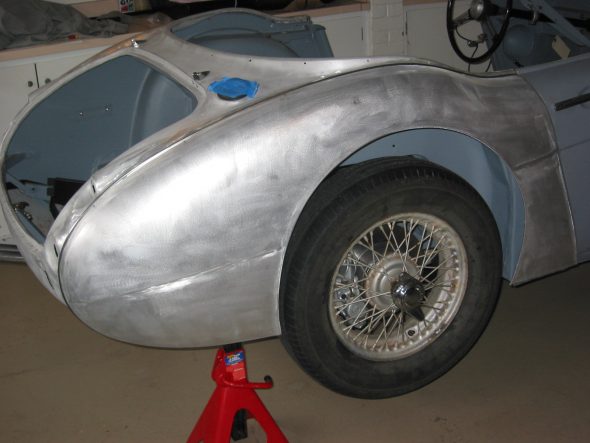
Wing right rear 1
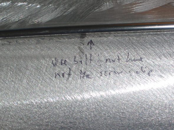
Wing right rear 3
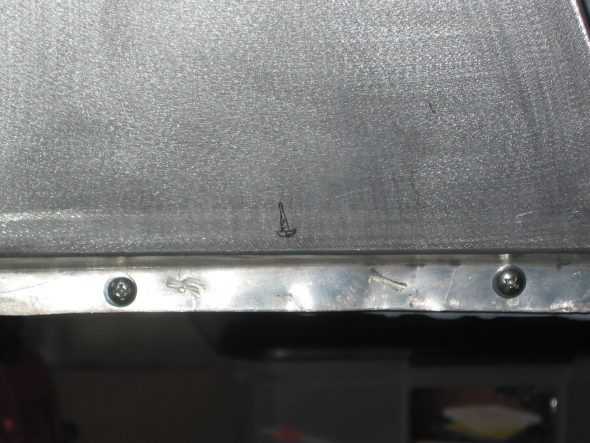
Wing right rear 4
Wing right rear 2
Front Shroud – Installed 3 flat head #10 x 1/2” machine screws in lip at front of the bonnet channel. Must catch the bottom frame rails on the inside first, then angle the back of the shroud up in the air – not easy to do!
Installed 5 flat head #6 x 3/8” sheet metal screws in lip at back of bonnet channel.
Installed two flat head #10 x 1/2” machine screws on each under bonnet vertical bracket. Couldn’t fasten properly on the left side because of the misformed panel at the left front corner of the superstructure.
Front Wings – Started with the fastener closest to the headlight. Then fastened the rearmost fastener. The long screws are used on the top of the wings. The clips with the shorter screws are used at the front of the wing by the turn signal lights.
Wing Right Front flange1
Wing Right Front flange 2

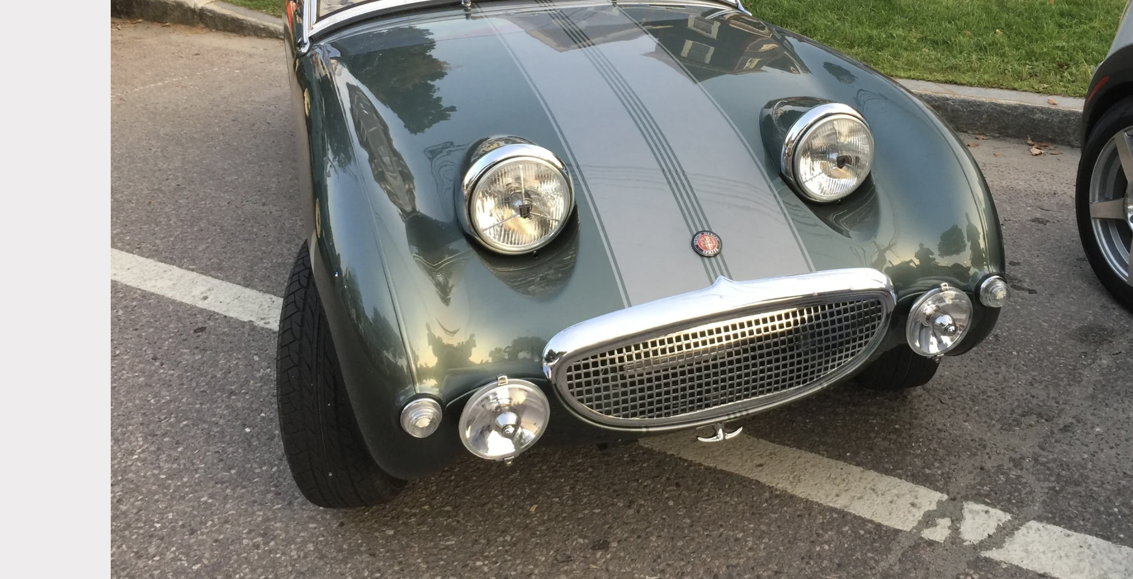
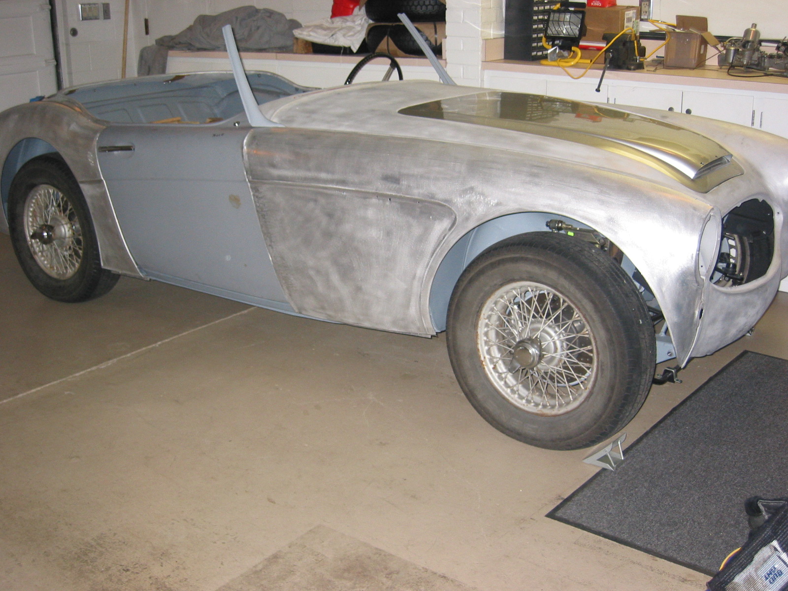
Car with wings 1
Doors – Pulled the door up and out and then tighten the hinge screws. May need to do some shimming to align correctly.
June 19, 2005
Side Curtains – I determined that It was better to purchase new side curtains rather than restoring my old ones. However, while the new frames looked quite good, I thought the old rear brackets were better formed than the new brackets. To dress them up and avoid rust in the future, I decided to chrome plate the old brackets.
Chrome Plating
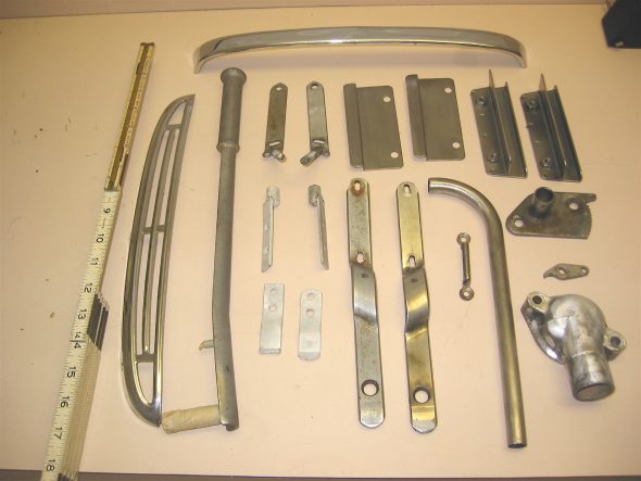
I sent a number of parts to Custom Chrome Plating in Pennsylvania for plating. Some were for replating and others were items that I just decided to chrome. I am a little concerned about getting too much plating in the windscreen frame channels but it will hopefully turn out alright.
1 Breather Pipe
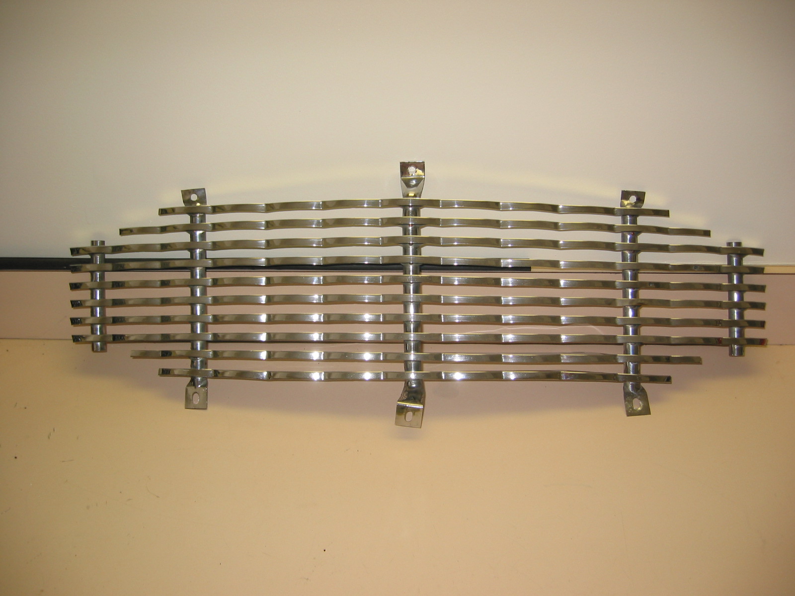
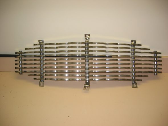
1 Bonnet Grille
1 Bonnet Grill Surround
1 Interior Dash Grab Handle
1 Interior Dash Grab Handle Escutcheon
2 Boot Hinges (2 pieces each)
2 Rear Seat Squab Retaining Channel Assemblies (2 pieces each)
1 Handbrake Handle
1 Handbrake Pawl
1 Handbrake Ratchet Plate
1 Thermostat Cover
2 Rear Seat Back Hinge Hardware (2 pieces each)
1 Windscreen Frame (4 pieces)
1 Front Grille
1 Boot Spare Tire Strap Staple
2 Side Curtain Brackets (2 pieces each)
Parts to chrome 2
Parts to chrome 10
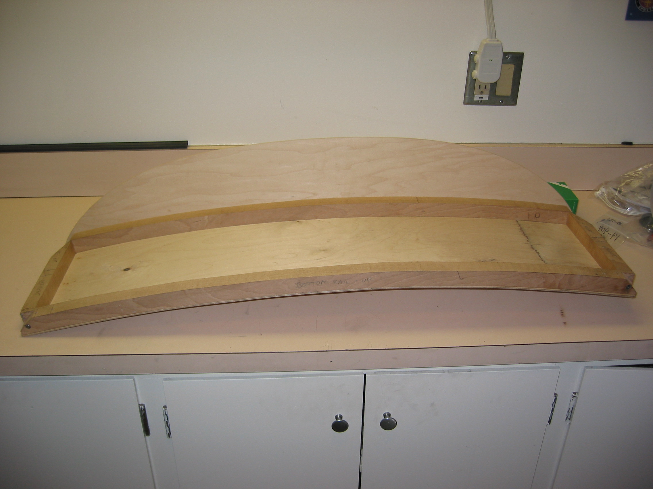
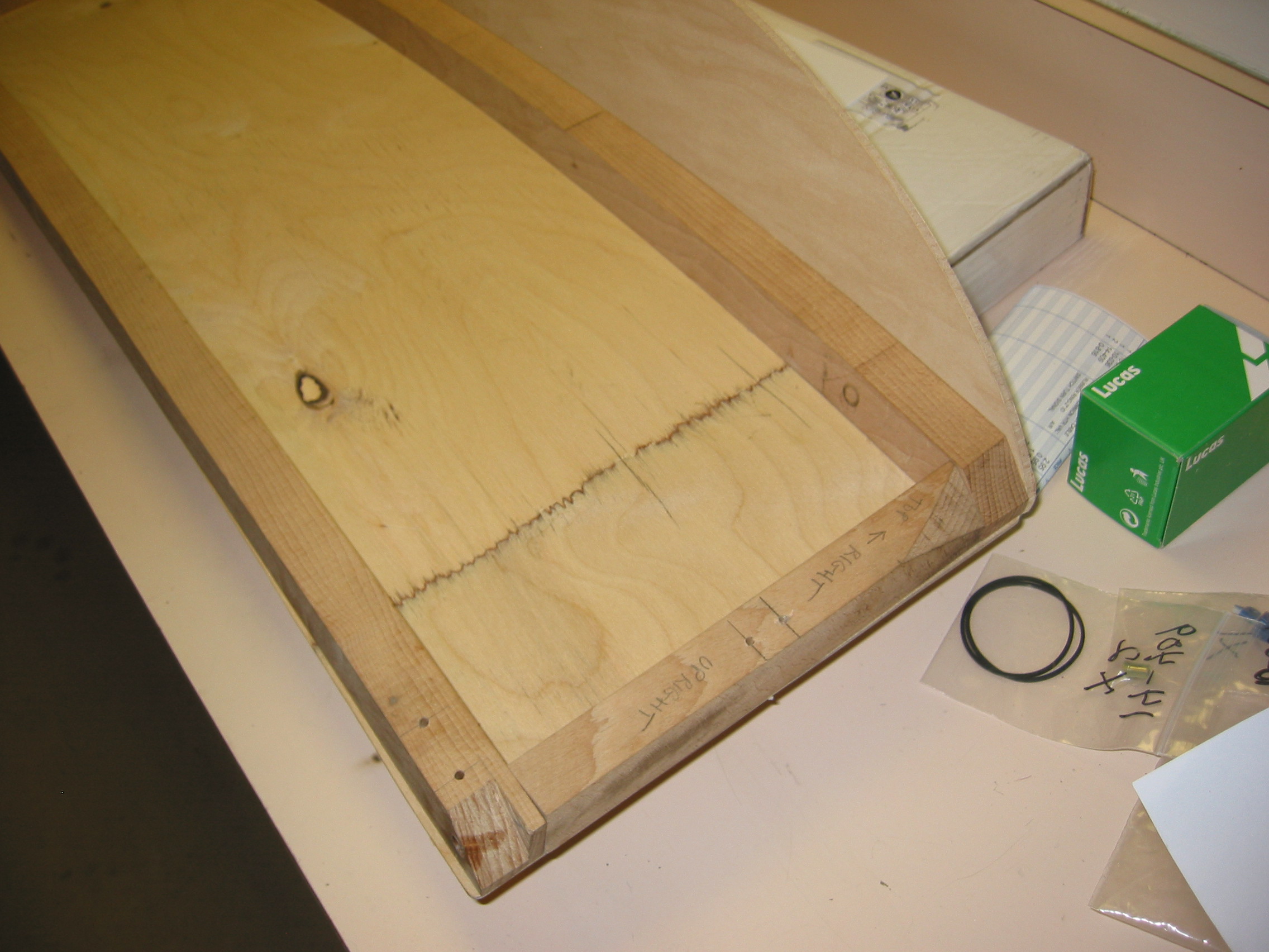
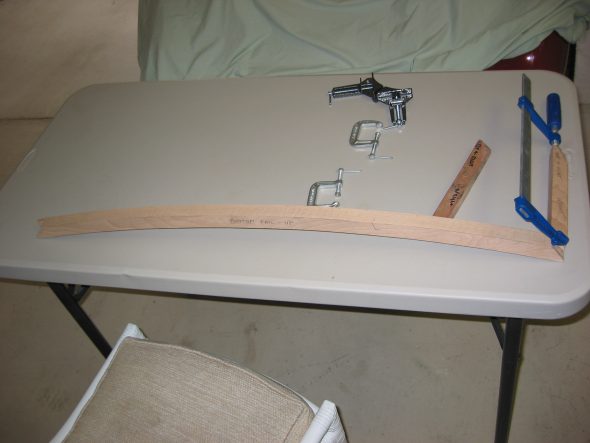
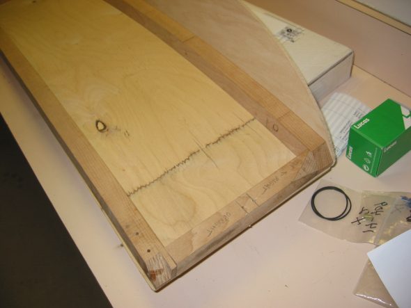
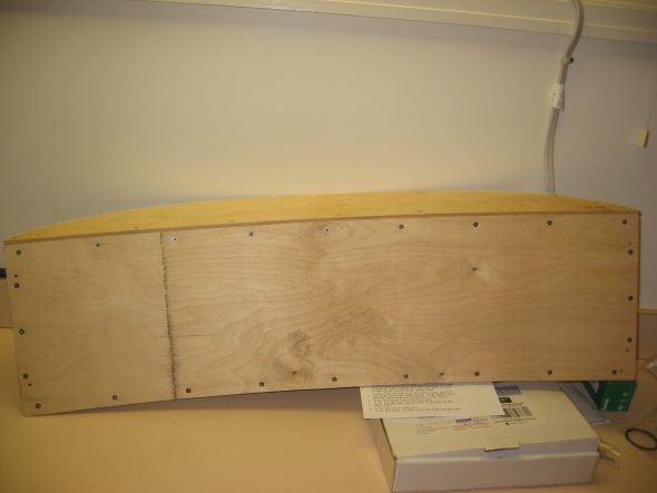
Rear Seat Squab
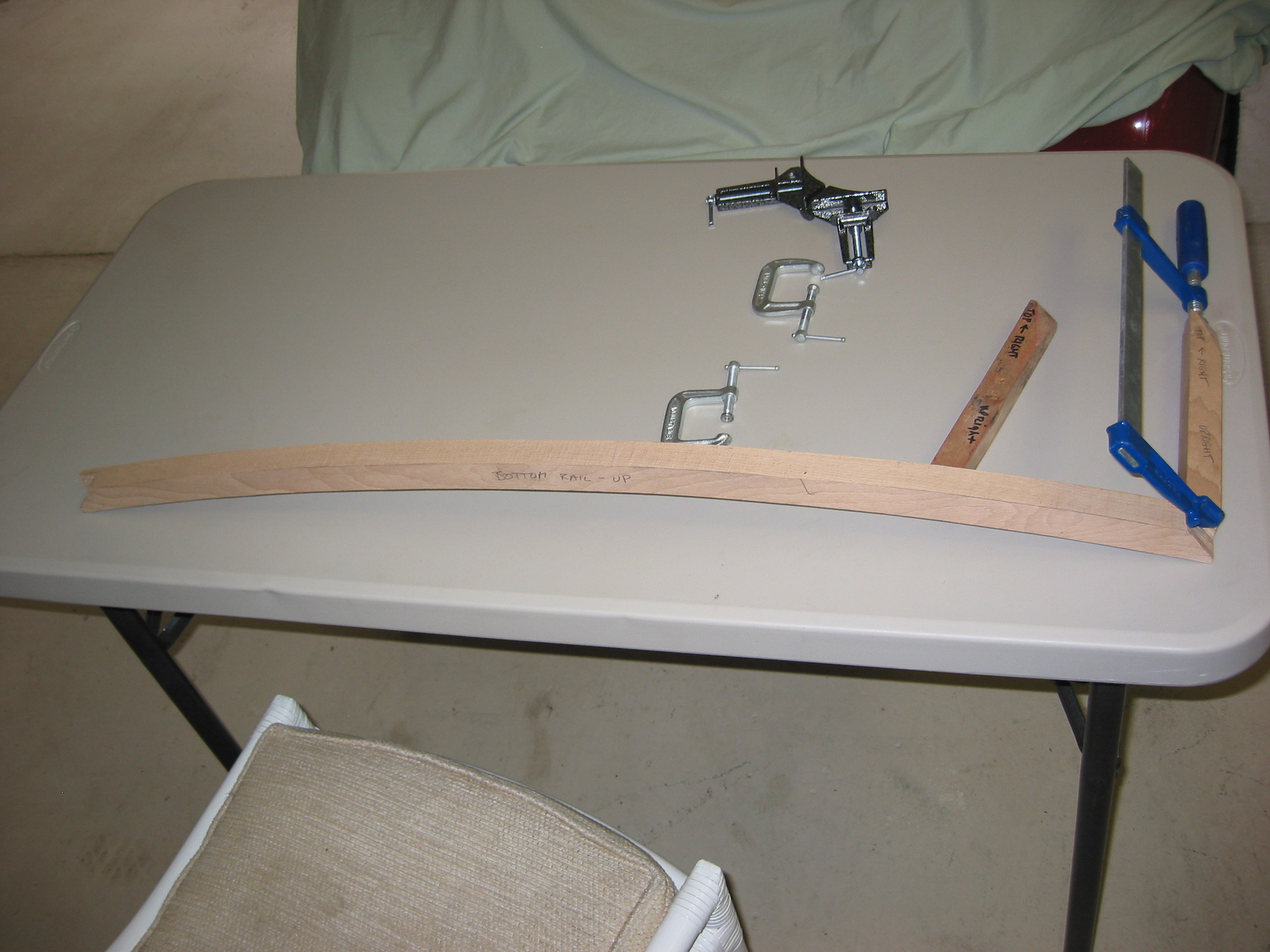
When I owned the car as a twenty year old I decided that rear speakers in the squab were more important than originality! I have decided to have the squab rebuilt by a local carpenter (He made the pieces and I put it together) before sending it to Heritage Upholstery and Trim for upholstery.
Rear Seat Squab assembly

Rear Seat Squab assembly
Rear Seat Squab assembly
Rear Seat Squab assembly
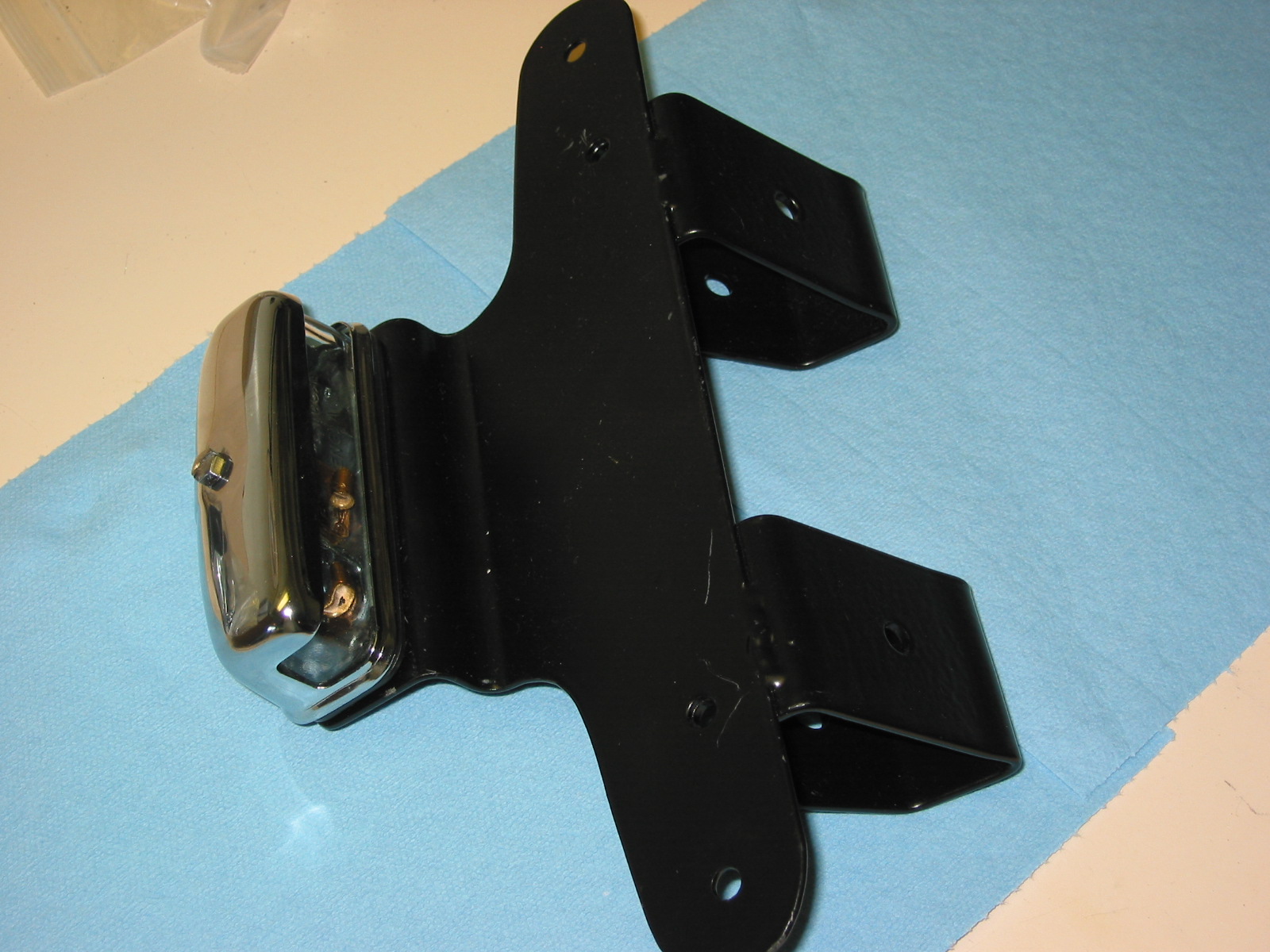
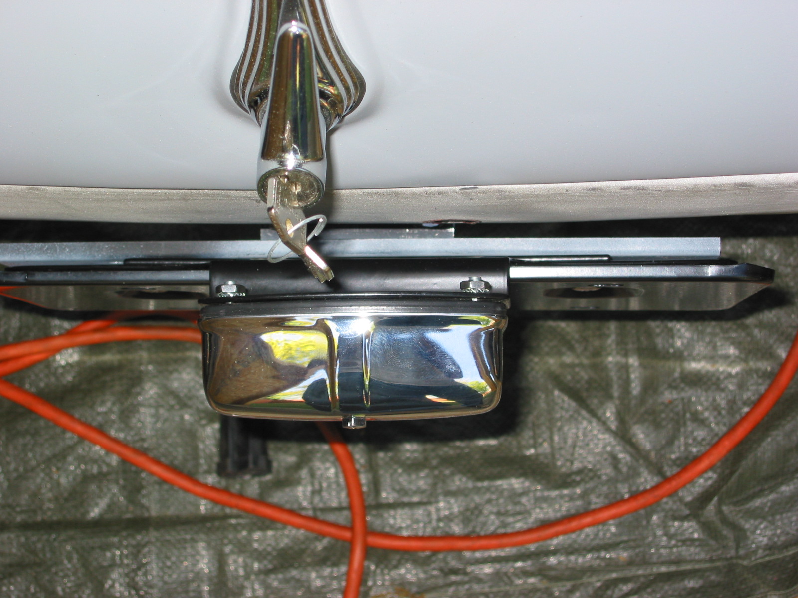
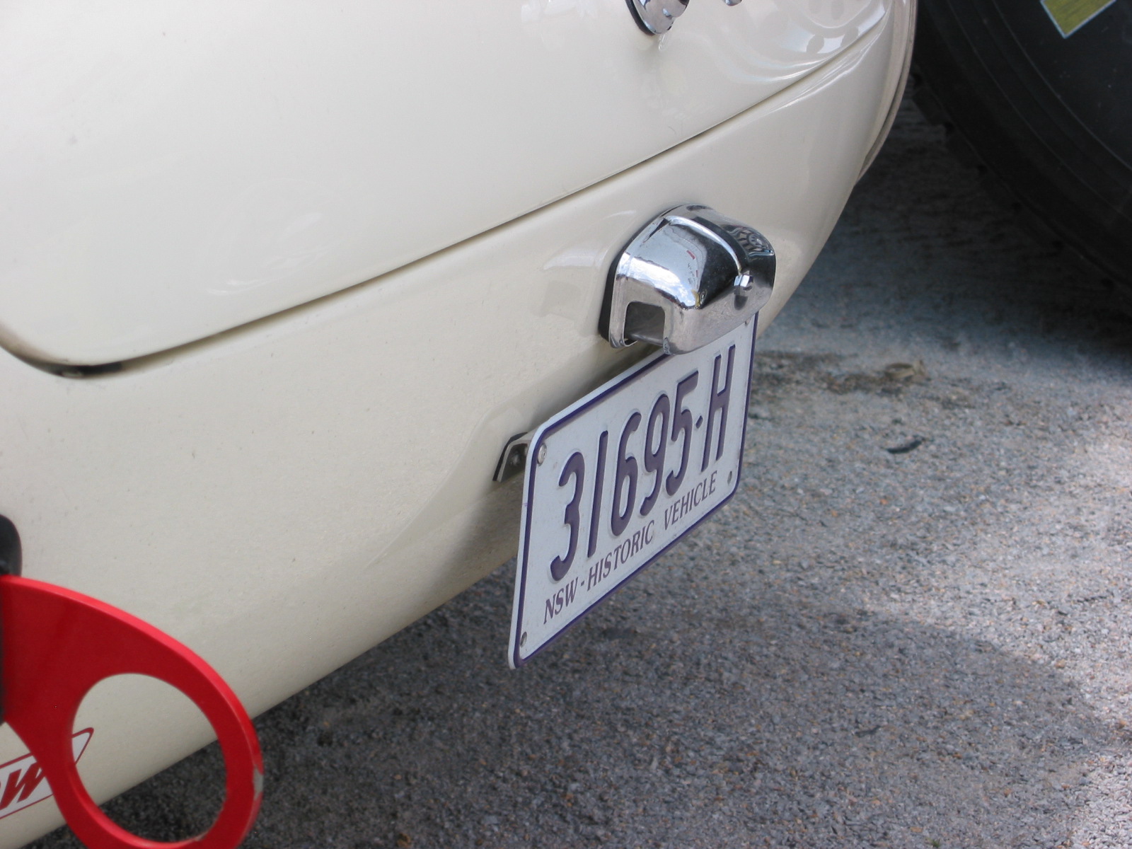
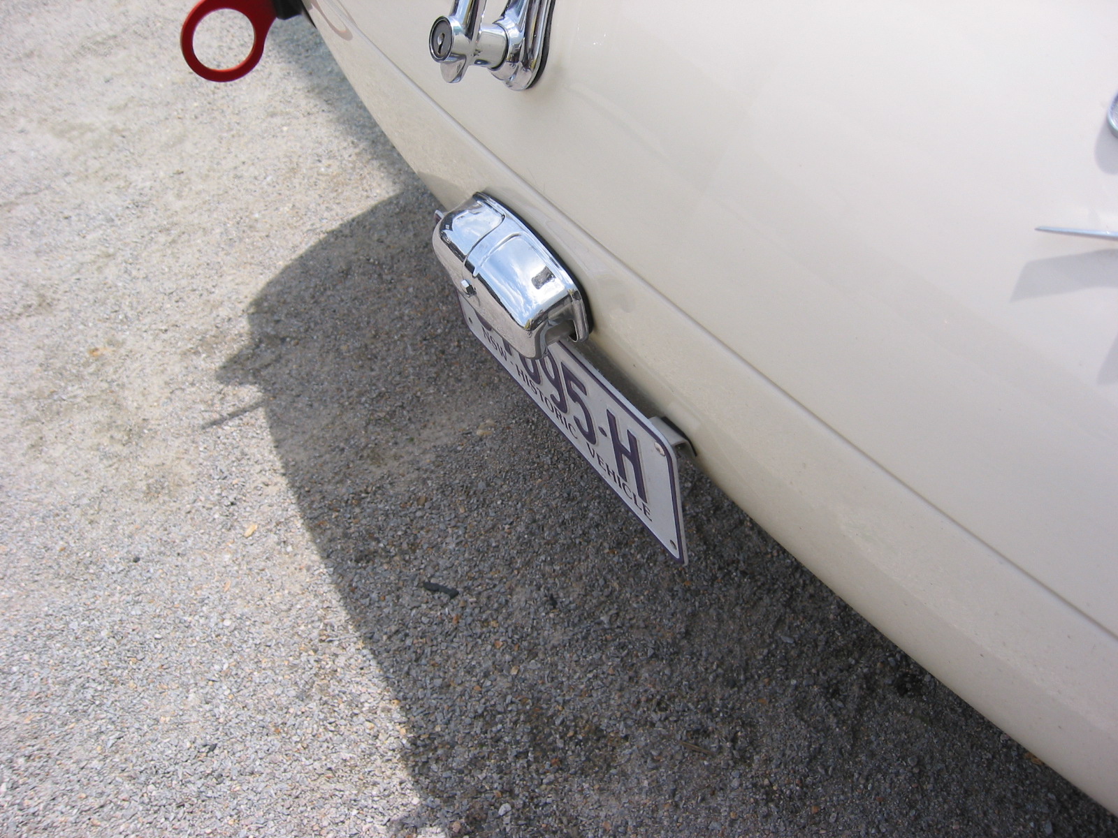
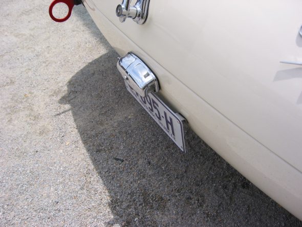
Rear License Plate Bracket and Lamp
Since I am using Rally car bumpers rather than the original full bumper I need to develop a new approach to mounting the plate and the lamp. I had fabricated something myself, but then decided to modify the BJ8 bracket and mount it directly to the car. I saw another approach on Aussie Peter Jackson’s BN7 at VIR and I may still do something like his.
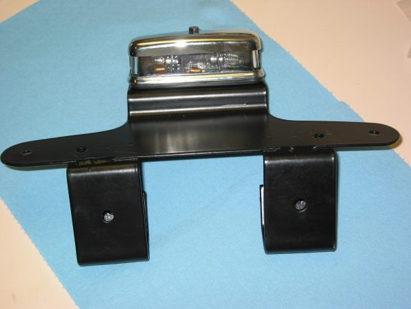
license & Lamp bracket 1
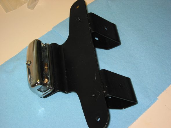
license & Lamp bracket 2
license & Lamp bracket 5
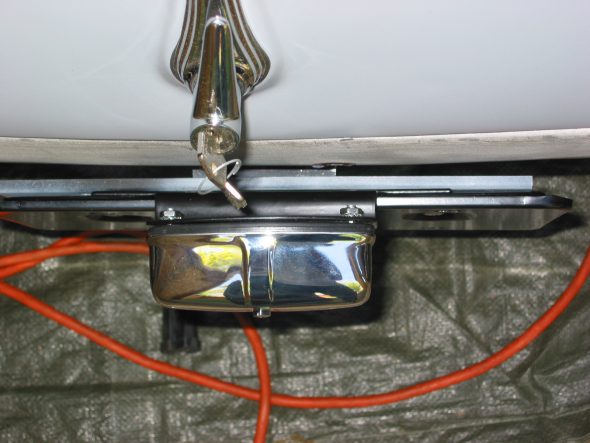
Peter Jackson’s car:
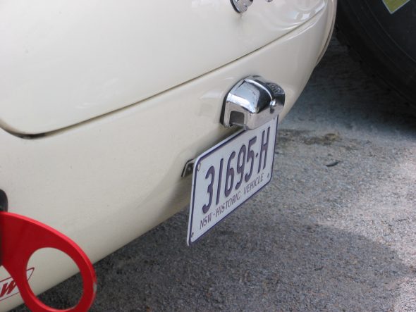
Peter Jackson’s Plate
Peter Jackson’s Plate
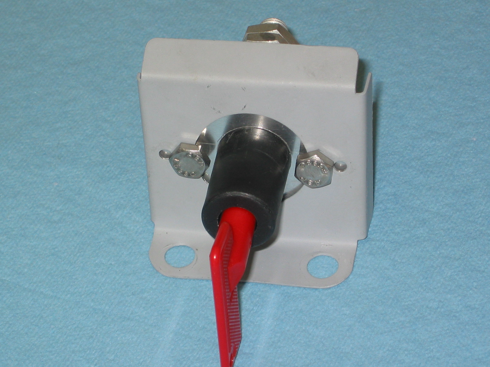
Battery Master Switch
So many have complained about problems with the original master switch that I decided to replace it with a modern equivalent from Hella. I mounted it in the original switch bracket.
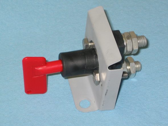
Battery Master Switch 1

Battery Master Switch 2