Chapter 44 Restoration Assembly, Week Eleven 2/26/2007

Time to install my Moto-Lita steering wheel and my rebuilt control head (trafficator) Trafficator(low res).pdf . This pdf will take a little while to download – lots of images! The installation was fairly easy and straight forward.  I inserted a length of thin wire up the tube and wrapped it around the first bullet connector on the wiring harness from the control head. I was then able to pull the wires down through the tube. I centered the wheel and tightened up the olive and nut at the bottom of the tube. Then tightened the three set screws on the steering wheel hub.

Moto-Lita steering wheel

After installing all of the electrical modifications I have made, I wanted to test things to make sure all connections were as they should be before moving on to the next task. So, even though I will disconnect them for final assembly at a later date, I wired the driving lights, headlamps, turn signals/brake lights as well as the license plate lamp.

The battery was then installed and (big breath) power applied to the system. One-by-one I checked the function of all systems. The right rear tail light turn signal did not function, the accessory lights did not turn on when the “clicker – remote control” was activated, the horns did not sound and my driving lights still needed some work. These items will be sorted out, one at a time, until everything is working properly. A little work remains, but I didn’t burn down the house or melt the car – a significant accomplishment!

I rechecked my wiring for the driving lights, made one change, and they are now functioning properly including the indicator light I installed on the new switch panel.

I made sure all of my ground connections were clean and tight and replaced the original flasher canister with a new one and now the flashers are working properly. The terminal connections are different than the original. Terminal X is equivalent to B (battery feed from fuse box — green wire),

Terminal L (Load, i.e., the feed to the bulbs — green/brown wire) and terminal P (Pulse, to the dash lights — light green/purple wire). Just as an aside, I did pop open the new flasher relay box to examine it for potential problems, only to discover the circuit board of a new solid sate unit rather than one with the original design.

Flasher Relay electronic guts

Following a consult with Michael Salter, I concluded that the reason my horn was not working was that the steering box was not grounded due to the paint on the box and the frame. Once some paint was scraped away from both I obtained a solid ground and the horn “honked” properly! I rechecked my wiring for the interior accessory lighting and they now function properly also.

Chapter 37 Restoration Assembly, Week Four 1/8/2007

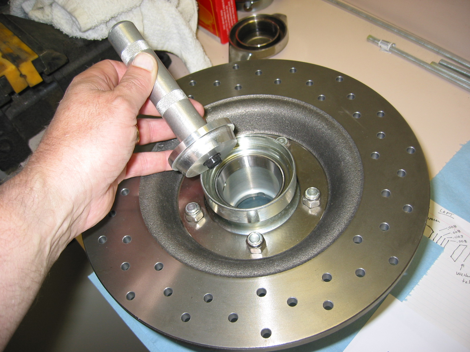
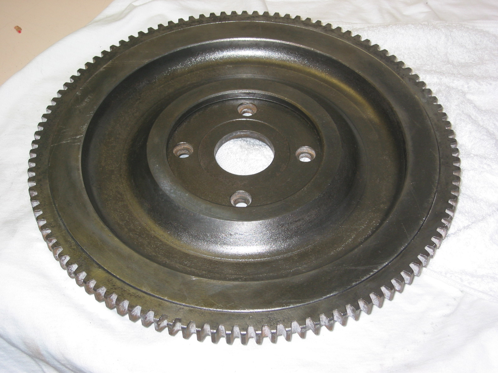
The front hub assemblies were the next parts to tackle. I had previously assembled new hubs to new drilled rotors. I fastened the rotor disk to the hub extension with 5 nylock nuts. Placed bearing races in the freezer so they would be easier to install in the front hub extensions. Then inserted inside bearing race with proper driver with the careful application of a hammer!, being careful to keep the race/driver straight. Turned the hub over and did the same procedure with the outside bearing race.

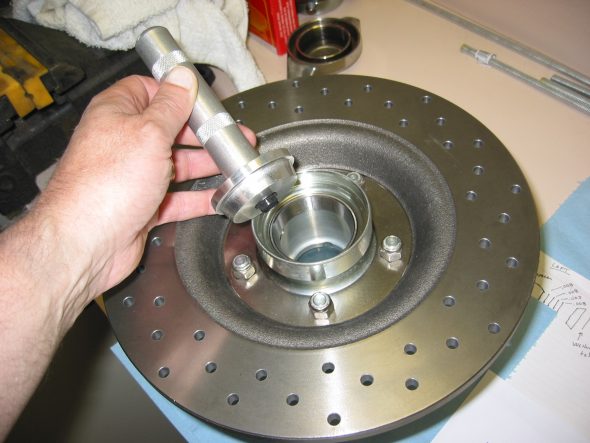
Bearing Race Install

Front Hub Bearings – Norman Nock and Doug Reid Doug Reid’s Front Wheel Bearings.pdf have produced some pieces that were very helpful for this process. I followed directions from Bruce at Healey Surgeons and put 90 weight oil on the inner bearing and offered it up to the spindle. The oil provided protection from damage due to the bearing running dry but at the same time, not give a false reading when trying to shim the bearings.

I then placed the spacer (cone) on the spindle followed by the hub extension. I then put an oil filled outer bearing on the axle followed by the tab washer and castle nut. The seal and shims were NOT added at this stage. The nut was tightened down to seat everything and then the works were disassembled. It can be difficult to get the outer bearing and the tab washer off – I used a magnet that worked quite well.

I then put the inner bearings, the spacer and selected shims on the axle. Starting with the thickest one .030, then .010, .050, .030, ( one of each ). I then put the hub extension on the axle followed by the outer bearing, tab washer and nut. I tightened to 40 lbs of torque and determined if one of the castle nut slots lined up with the hole in the axle for the split pin. I took care that the shims were all the way up on the shoulder of the spindle axle so that they did not get mangled when the nut was tightened. The final proper adjustment is correct when you can tighten on the nut and the wheel does not show any reduction in ease of turning with no play.

Bruce indicated that if the rotor drags when you tighten the castle nut, then you need to add shims. If it is to loose, you need to remove the shims. When it is correct, re-tighten to the correct specs. At this point, the hub should be turning freely, with no end float and no pre-load. This was a trial and error process and took a while to complete.

Once I was satisfied that I had the bearings set up correctly, I removed everything, keeping careful track of the shims! I then packed the wheel bearings with wheel bearing grease and installed the front seal. The seal has the spring facing the bearings. I then placed the spacer in the hub extension and bearings in first, and then reassembled unit.

I torqued the nut to the 40-70 lb setting, lining up the hole in the axle with the nut and placed the split pin through the hole in the spindle axle, and then pulled one tab of the pin forward and bent it back over the axle end. I then pushed the grease cap on to the axle ( do not fill it with grease) and gave it a tap with a drift.

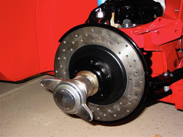
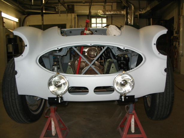
Rotor and Hub Install

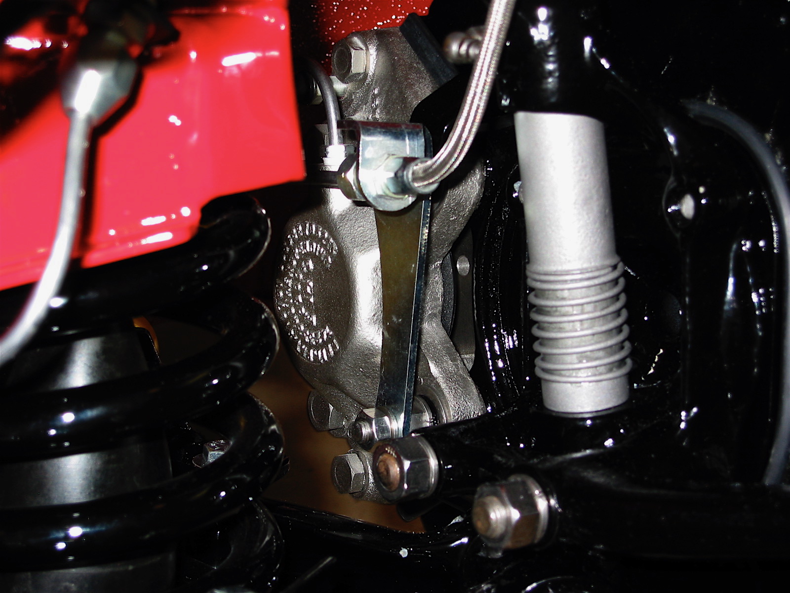
The time has come to install the front brake calipers, the hose brackets and the brake pads. The calipers mount through the brake dust shield and into the swivel axle. My calipers were rebuilt by Healey Surgeons. I used stainless steel flexible brake lines rather than the stock rubber lines.
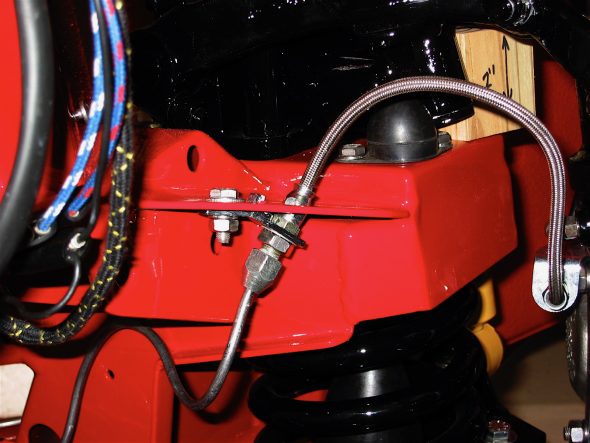
SS Brake Line RH 2


Brake Caliper

Mintex pads, MGB 520, were used initially, although I may switch to “greenies.” Shims were used between the pads and the pistons with an application of Permatex Ultra Disc Brake Caliper Lube #24110. All hose and pipe fittings were checked and tightened with teflon tape used on all threads.

I converted the overdrive relay into a relay for the driving lights. The image to the right illustrates the mounting location, again, using nutserts.

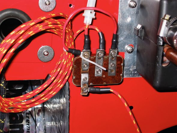
Driving light relay 1

Chapter 29 – Cleaning and Trial Fitting

September 4, 2006

Initial Work on the Engine and Driveline

Clutch and Flywheel – Many who have used the Smitty gearbox conversion have suggested fitting a later BJ8 diaphragm clutch rather than the the spring actutated clutch originally used on the BT7. Now seemed to be the time to do it, so I ordered the clutch plate assembly from Moss. I also took the suggestions of others and sent my flywheel to Bill Bolton in exchange for a lightened (now 24 lbs.) BJ8 flywheel. The wheel that came back from Bill was pretty rusty in the non-contact surface area so a little time was spent with rust remover and the drill and wire brush. Even after cleaning, I still think I will give it to Jeremy to media blast the non-contact surfaces.

BJ8 lightened Flywheel 1

BJ8 lightened Flywheel 2

September 6, 2006

Jeremy Turner’s Work Continues

Rear shroud with filler 2

Rear shroud primed 1

Rear shroud primed 2

rear shroud final primer

Shrouds – Jeremy is working on the “Bloody Beast” with the idea of completing all the priming and final panel fitting withn two weeks. He is focused on my car completely. He has just completed the body filler and priming for the front and rear shrouds.

Front shroud bodywork 2

front shroud poly primed

Front wing final primer

right front wing final primer

Because Martin Jansen did not put the bumper bracket mounting tubes all the way through the frame, Jeremy needed to weld some short tubing into the inside of the frame rails to mount the Cape International driving light/tow hook.

tow hook mount

tow hook mount 2

And now, don’t those Lucas drving lights look nice!

Fitting driving lights 2

Fitting driving lights 1

Fitting driving lights 3

Final priming on doors and rear wings.

Doors final priming

Rear wings final priming

September 11, 2006

Jeremy Turner’s Work Continues

Before going any further, it was a good idea to check the fit of the radiator, fan and the body and bonnet grilles to ensure a good fit. The radiator cap did hit the bonnet so some more work was required to adjust the radiator and shroud. We ended up with about 1/8” clearance between the radiator cap and the bonnet. The bottom trim piece on the body grille wold not fit properly so it was decided to have the original rechromed.

Radiator installed

Fan installed

Bonnet grill installed

Shroud with grille