Chapter 76 Week Forty-Six October 29, 2007

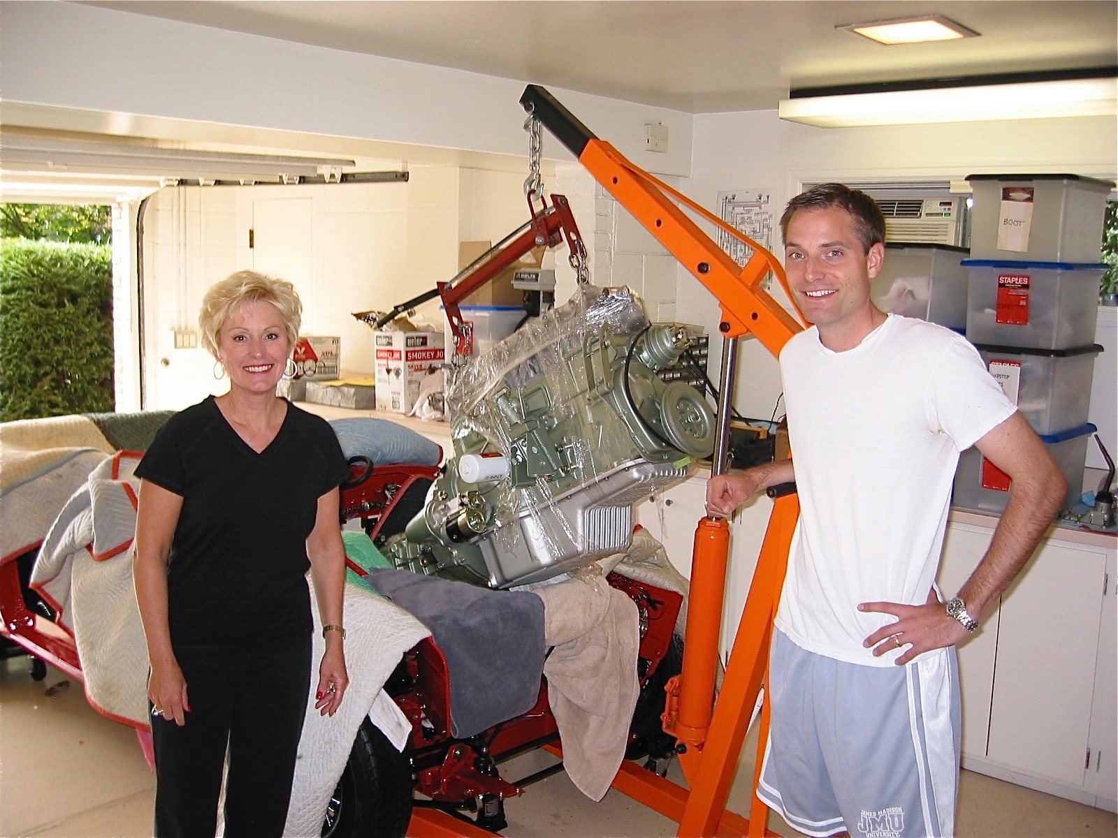
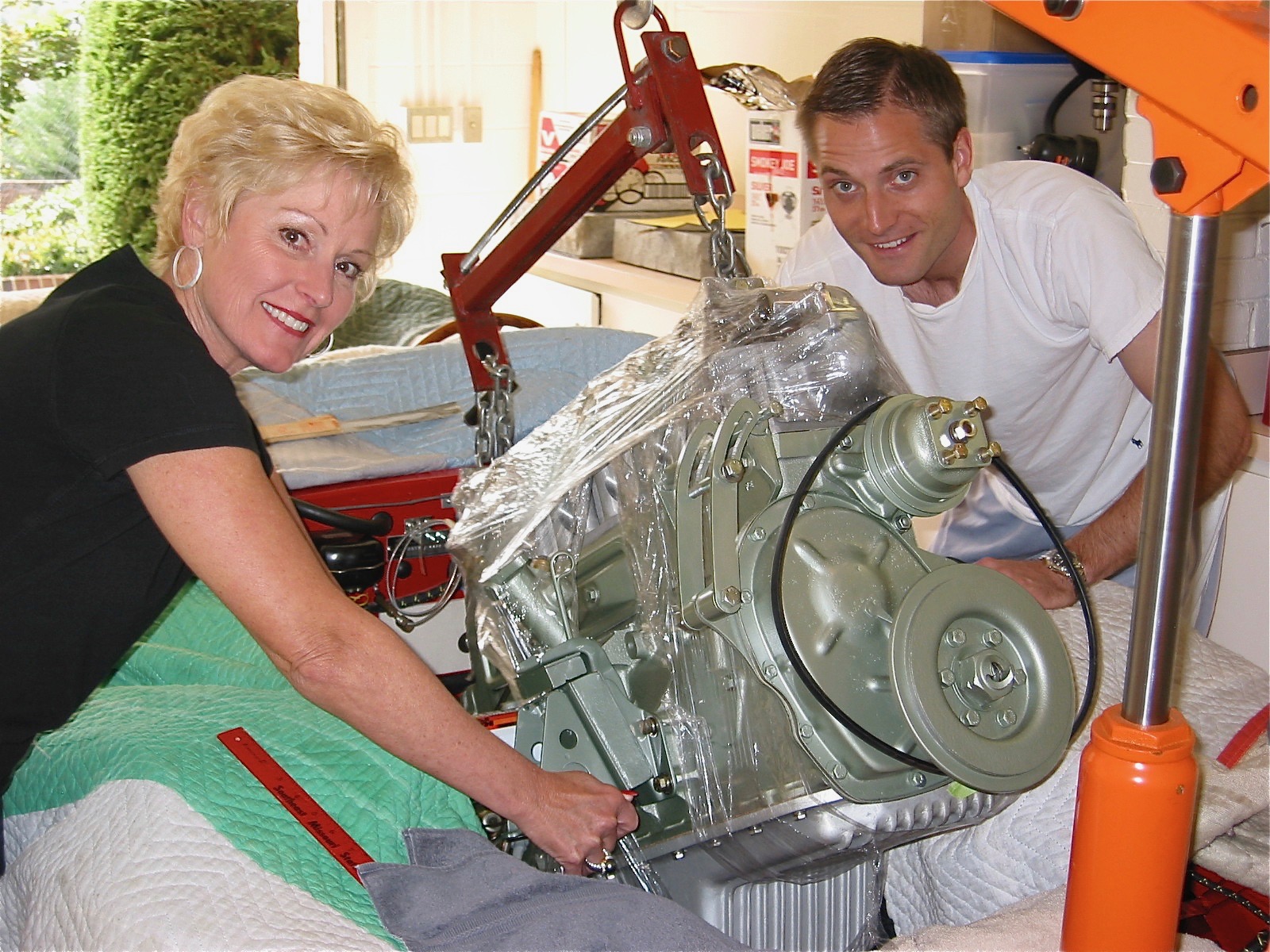
I am not quite ready to start the engine because I am waiting on my custom made propshaft, currently being fabricated by Dale Engineering. However, there were some close to final matters that needed attention as the day to fire up the engine approached. Jack Harper from Coachworks, Ltd. who assembled my rebuilt engine, came to the house to assist with readying the engine.

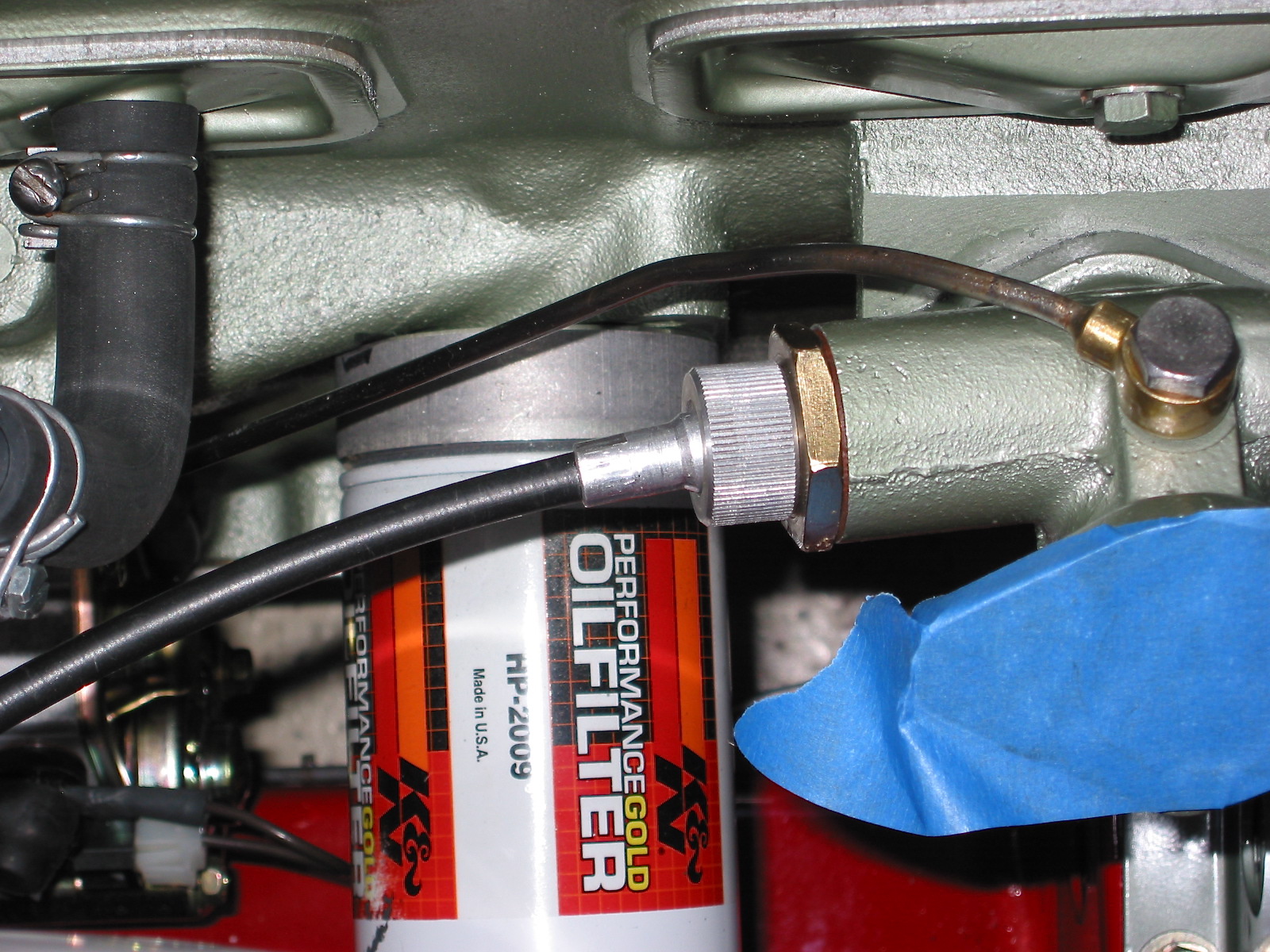
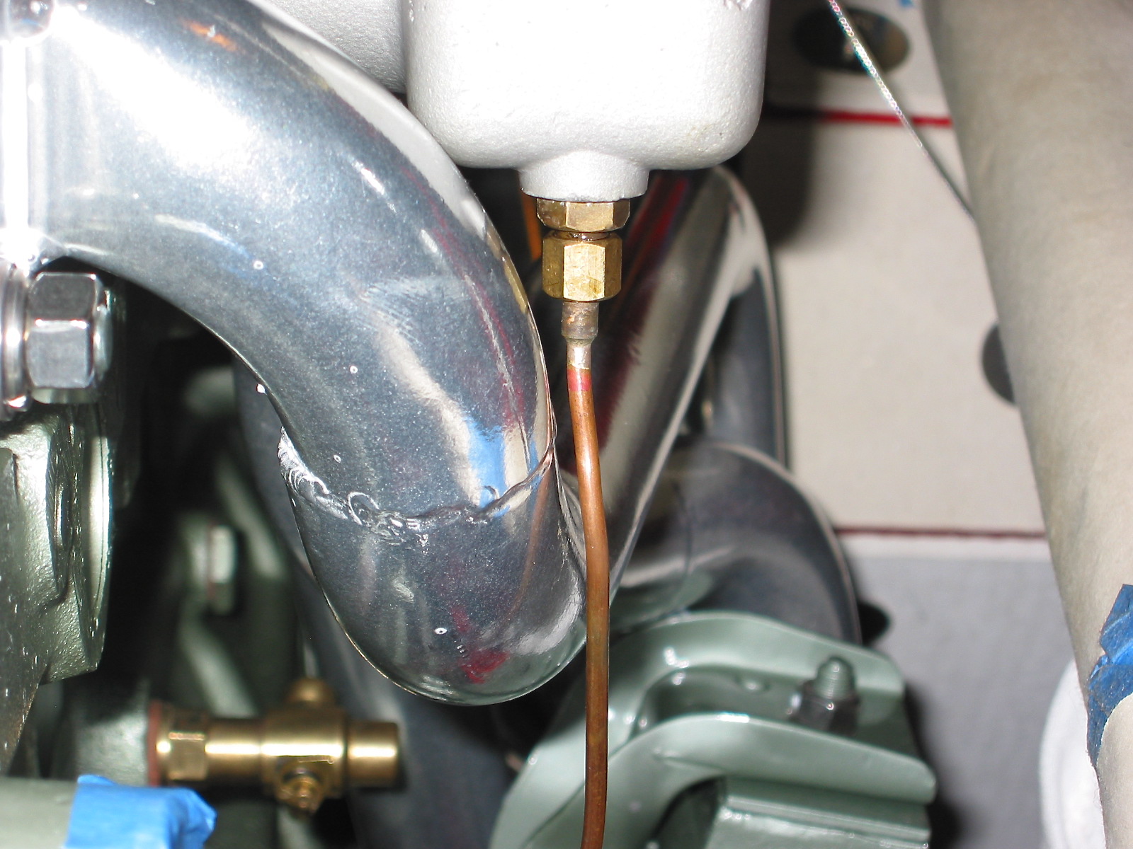
Our first step was to “pump” some engine oil into the engine to ensure that everything was coated. Jack attached a compressed air canister with two quarts of oil to the oil pressure pipe union and then forced the oil into the engine with air pressure. As we neared the end of the oil transfer one could see the oil emerging from the top of the rockers and then the end of the transfer was signaled by a large “burp” that one could easily hear.

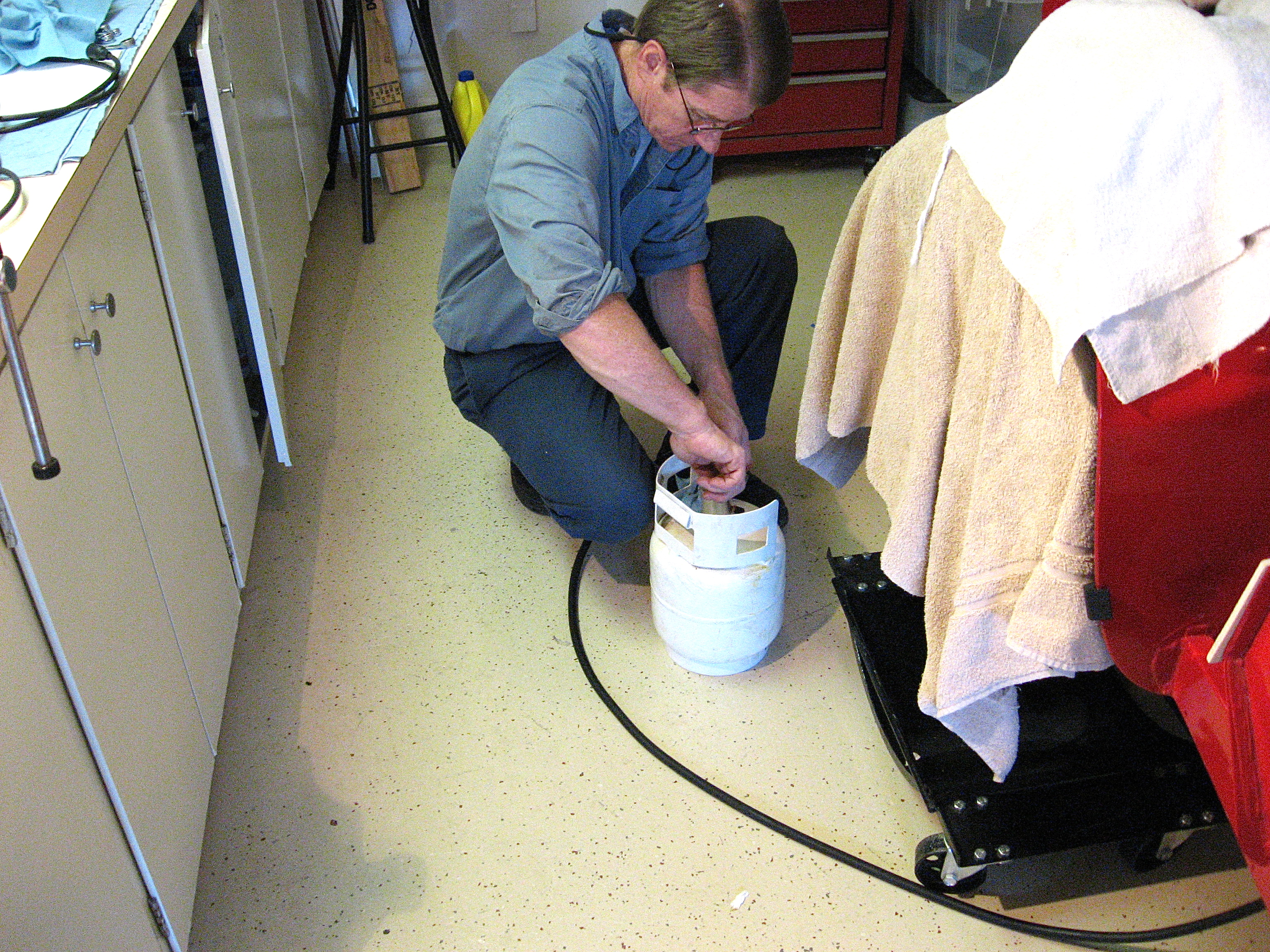
Jack Harper engine oil

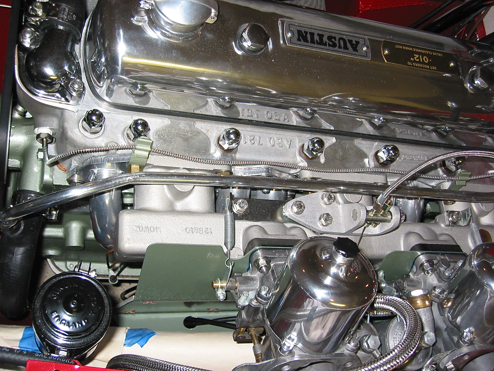
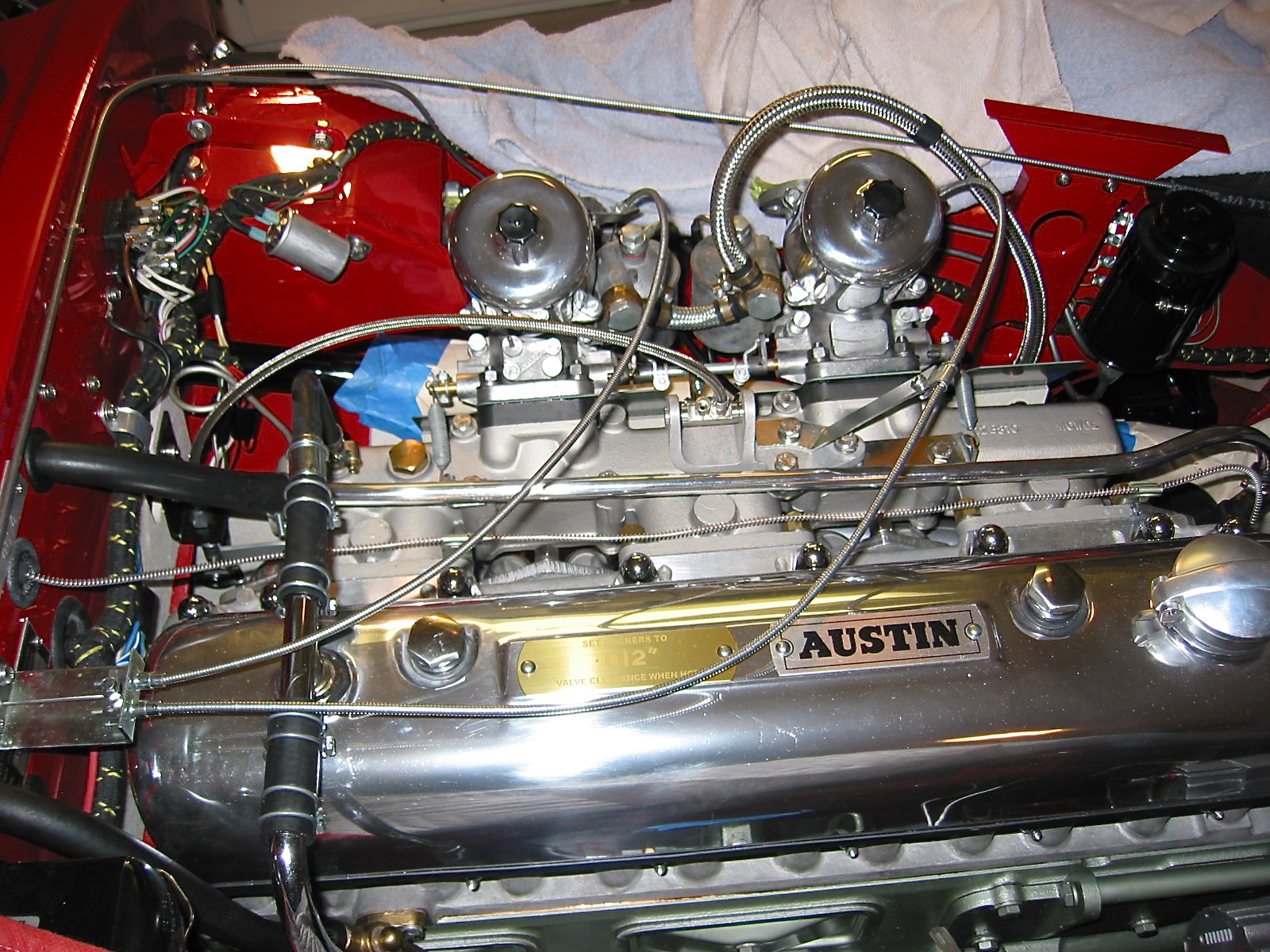
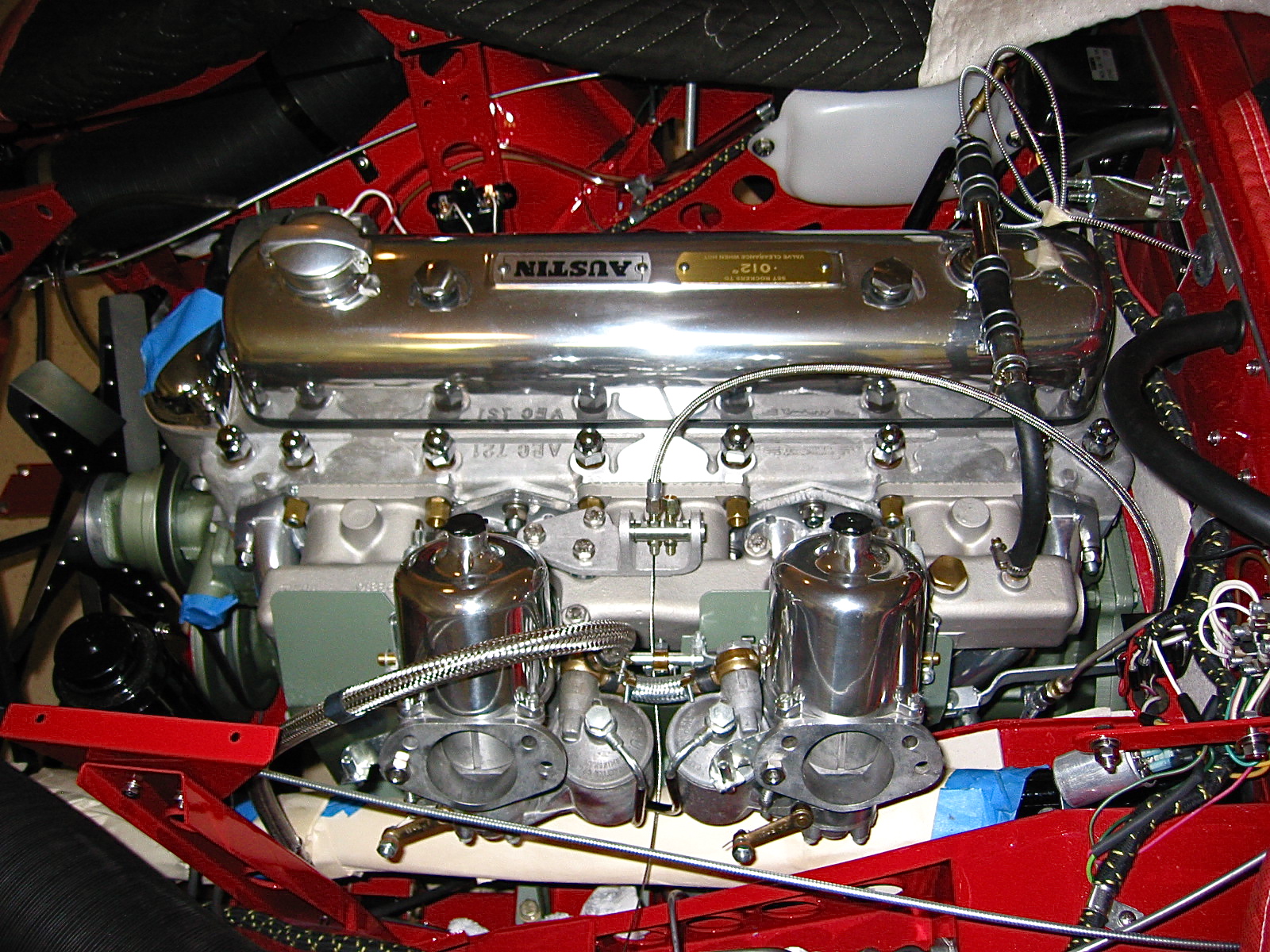
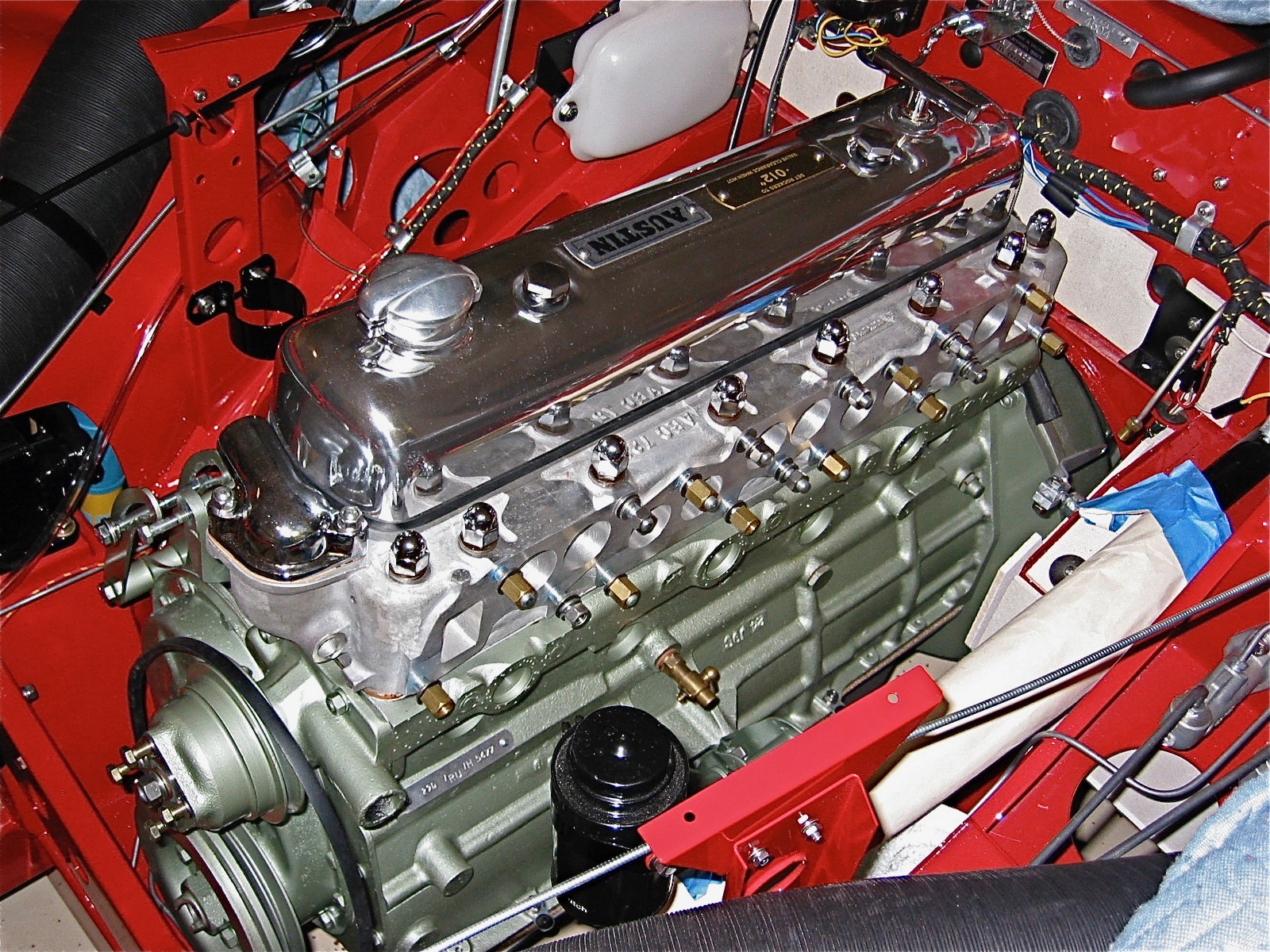
We made sure the pointer and timing mark were aligned and then went about checking the valve gap for the assembly. I used the starter to turn over the crank as we checked each rocker/valve. We then secured the Capesport Alloy rocker cover and added another 5 quarts of oil. The rocker cover was sourced from Cape International.

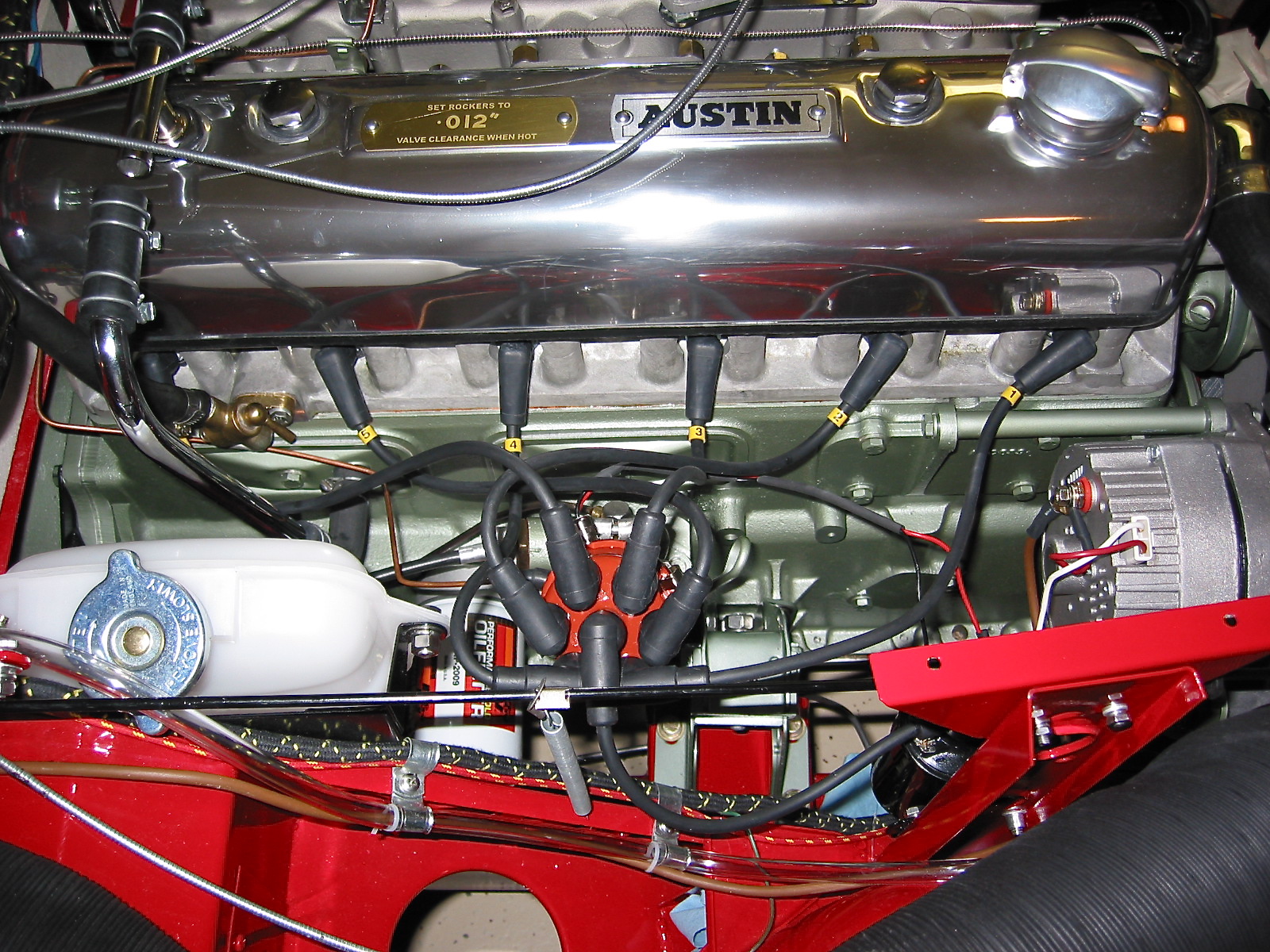
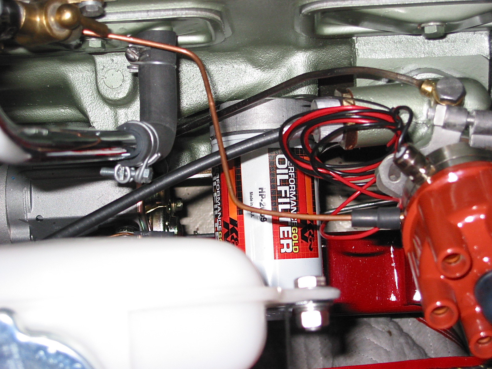
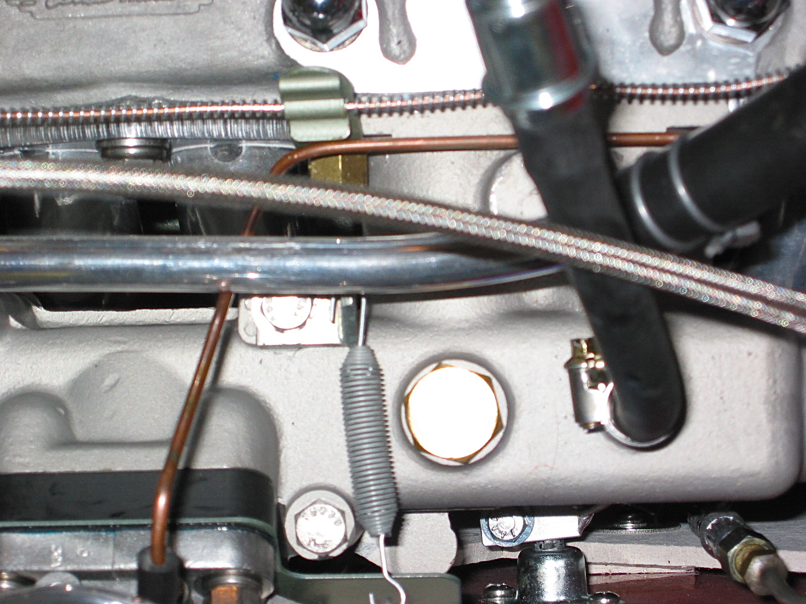
Capesport Rocker Cover & Ignition Wiring

The oil I chose to use is Valvoline racing oil, 20-50 with ZDDP.

Valvoline 20-50 Oil

I had taken the NGK spark plugs out to rotate the engine. We put a little anti-seize on each plug, checked the gap and re-installed each one.

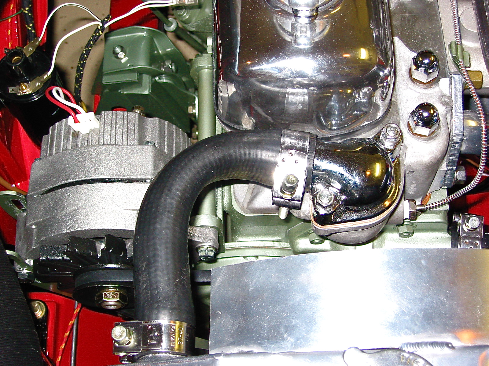
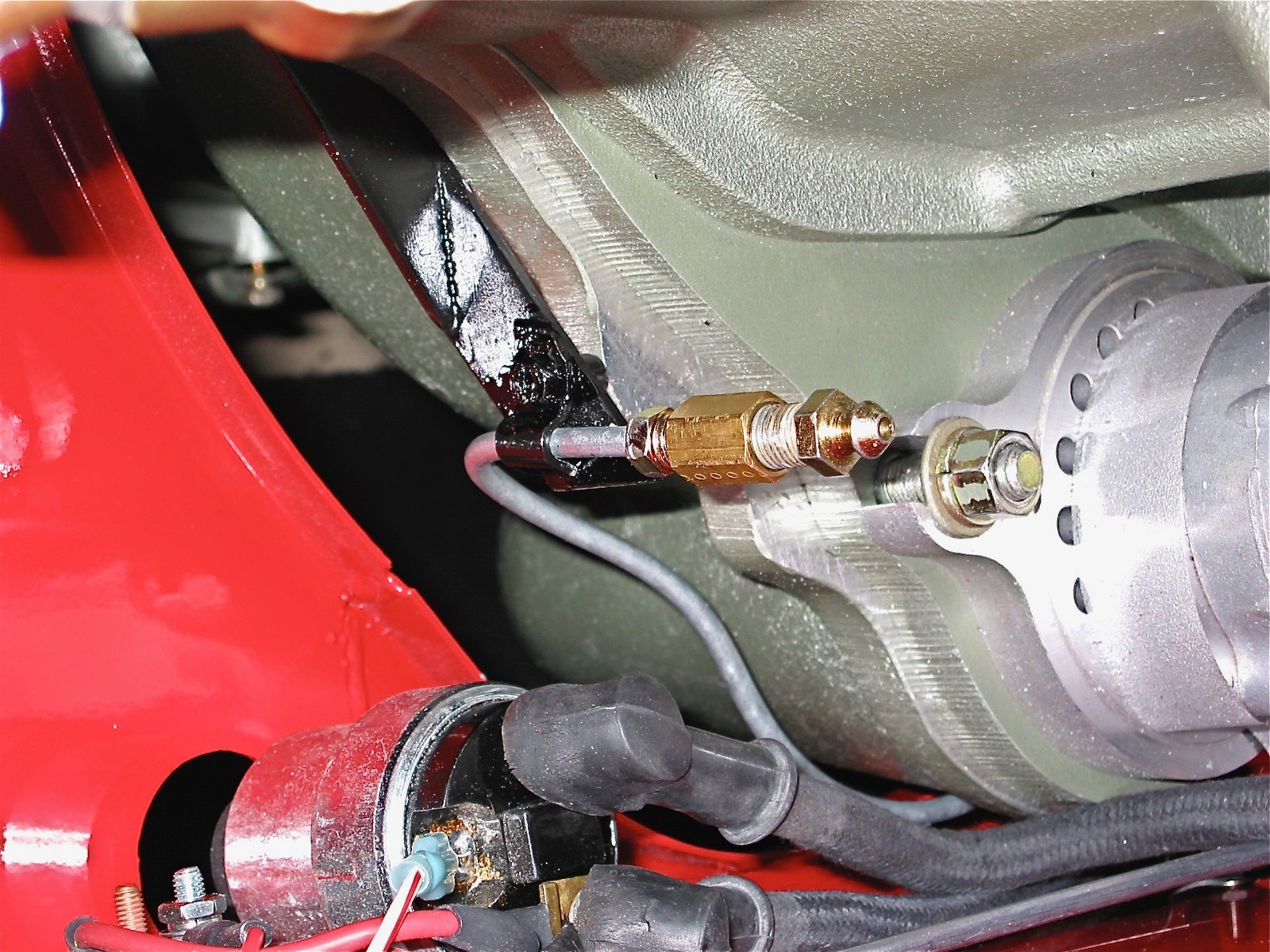
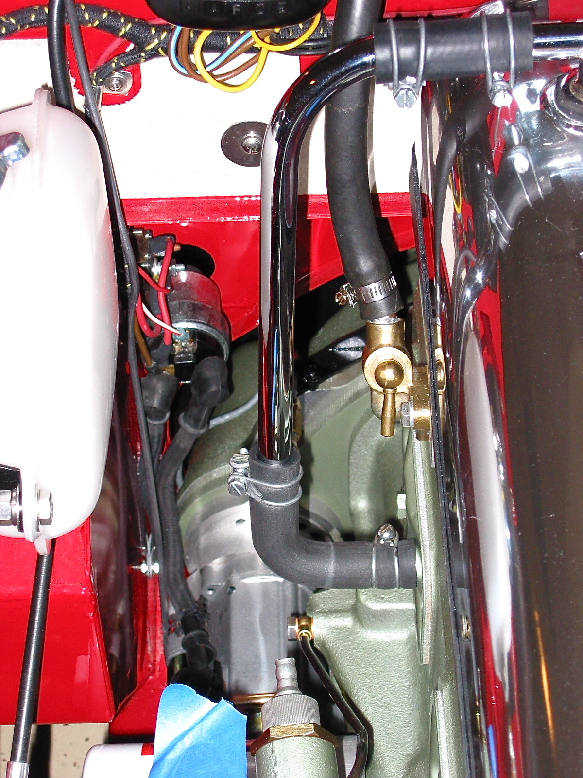
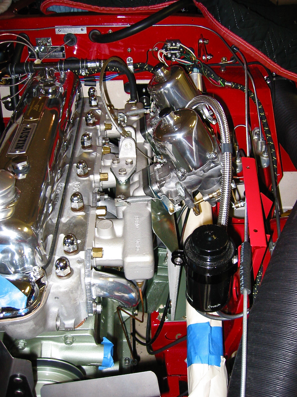
In recent months the 123 distributormanufactured by a Dutch company, 123 Ignition, has received some very good press. I had originally planned to use a Mallory Unilite distributor, but I decided to give the 123 unit a try.  One appealing aspect of the 123 is that the advance curve is determined by simply adjusting the settings by turning an adjustment on the outside of the distributor and “clicking” it into place. For initial set-up, I chose the recommended “B” setting. While the distributor is a “drop-in” in for the BJ8 with an electronic tach, a kit is supplied to adapt it for the mechanical tach drive of the BT7. The shaft did need to be drilled and the drive dog from the original Lucas unit installed with a few spacing washers. My unit was supplied by a German vendor Brits’N’Pieces. Jack installed the distributor and I installed the Pertronix igntion wiring to the plugs and to the Pertronix “Flamethrower” coil. The coil was previously mounted vertically on the shroud brace. Several of the wiring leads on the original wiring harness for the ignition were no longer needed so I simply used plastic ties to fold them down and secure them, in case they might be needed at some point in the future.
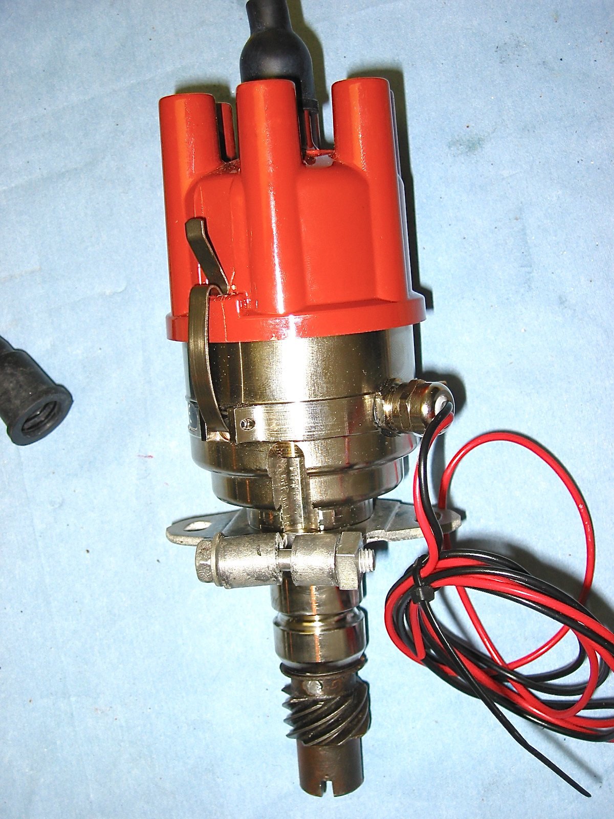
123 Distributor

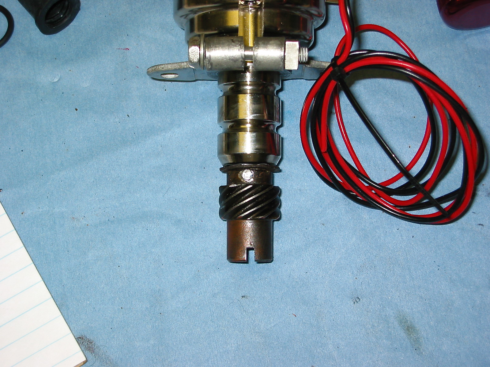
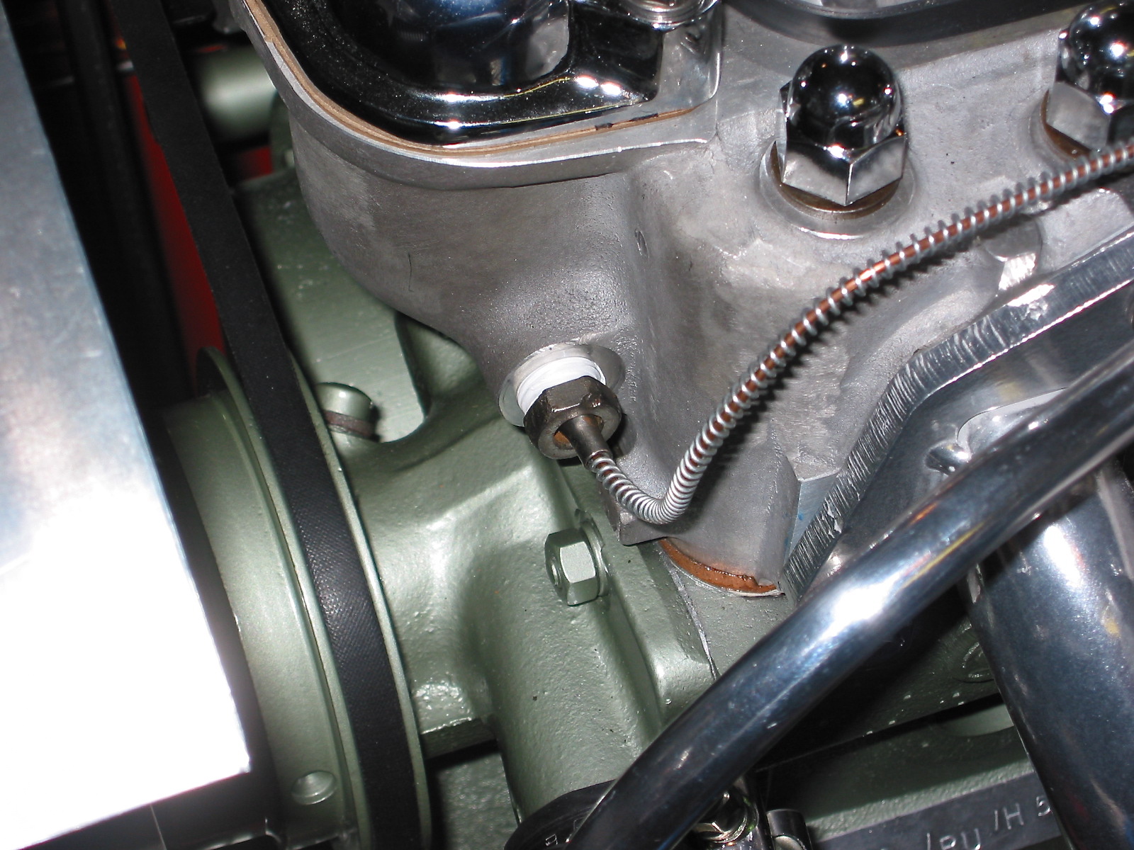
123 Distributor drive dog

123 Distributor.  Purchase Information and instructions.

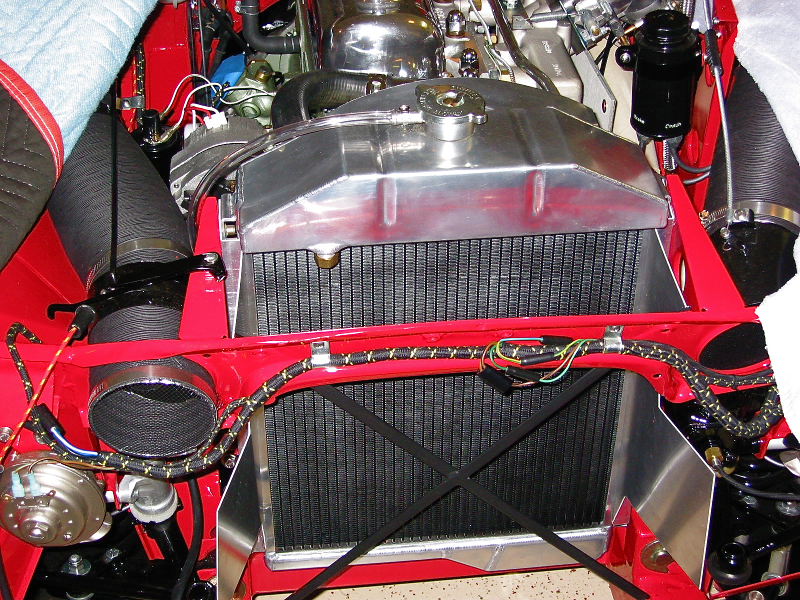
My next step was to add coolant to the radiator. I used Prestone 50/50 premixed formula. Fortunately no leaks!

I had been using an old battery for checking out electrical function throughout the restoration process, but it was now time to buy the battery I would be using in the vehicle when it was a road car and not a garage car! I decided on the Optima. I purchased it at the local Batteries Plus store. They are not cheap at about $160 dollars, but I like the idea of the no-leak gel in the boot of a car. The model number I purchased was: Part Number: 34 (8002-002) RedTop®; Battery; Group 34; Cold Crank Amps 800; Crank Amps 1000; Reserve Capacity 110; Ampere Hour 50; Top Terminal; L-10 in.; W-6 7/8 in.; H-7 13/16 in.; UNBOXED. The battery was secured in place with the battery fixing bar and rods.
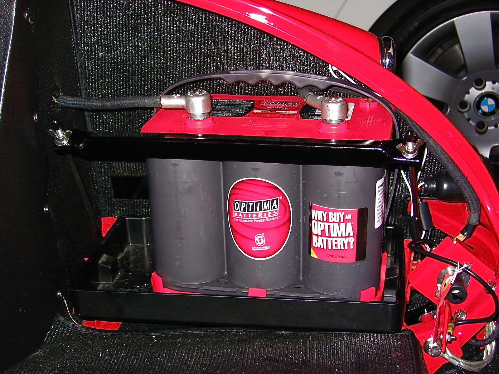
Optima Battery

Because the Smitty Bell housing fit a little high in my car????, I custom fabricated a gearbox cover extension to provide a little more room for the housing. This also required custom fitting carpet. I had ordered a couple of extra yards of carpet when I ordered my interior from Heritage Upholstery and Trim for this purpose. I first covered both sides of the cover with Dynamat Extreme and then cut and glued the carpet to the cover.

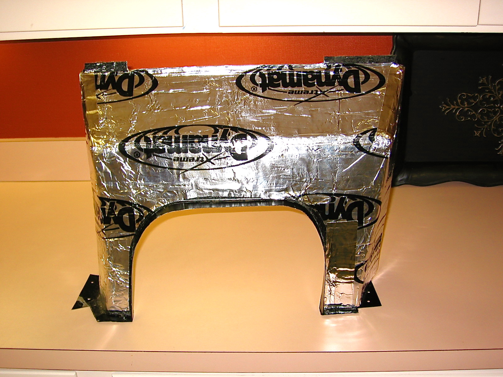
Gearbox cover extension 1

To assist with interior cooling and weight, I ordered a fiberglass gearbox and propshaft cover from British Car Specialist. The original cover was metal and mine was too far gone from rust. Using a fiberglass cover also made it easy to fill the original hole for the side shifter and cut a new hole in the center for the Toyota gear shift. I used an MGB trim ring and rubber seal for the gear shift lever sourced from Moss Motors. Using a helpful hint from Doug Reid, “Mr. Finspanner,” some JB Weld was used to glue four “T” nuts to the bottom of the fiberglass cover so that machine screws could be used to mount the ring, rather than sheet metal screws that overtime would fail to secure tightly in the fiberglass. 

Chapter 75 Week Forty-Five October 22, 2007

I continued with the assembly of various engine components in the forty-fifth week of restoration. I learned the hard way that the vacuum line from the intake manifold to the distributor needs to be one of the first items to install on the engine, not one of the last! However, after a number of trial fittings I did manage to get the pipe installed with only having to disconnect a few hoses. The copper pipe slips into rubber connector fittings at the manifold and distributor.

Vacuum Pipe RH side to distributor

Vacuum Pipe LH side to rear carb

The capillary tube running from the water temperature/oil pressure gauge to the fitting on the LH front of the cylinder head was the next item to install. Two small mounting clips and brackets were first mounted to head bolts securing the intake manifold and the tube was slipped under the clips, and the temperature sensing bulb inserted into the head and screwed home.

Capillary tube mounting

Given all of the typical concerns about overheating with the Healey engine, I decided to use a six blade aluminum fan sourced from British Car Specialists, The fan comes with an aluminum spacer to fit between the water pump pulley and the fan.

Stainless Flex Fan

The aluminum radiator and custom made air deflectors were the next pieces to go on.  The radiator was ordered from Cape International and I must say that the craftsmanship is superb. The aluminum deflectors I had made caused the radiator to be a tight fit, but with patience all components were secured into place. I put a light coat of black radiator paint on the front surface of the radiator to give a standard appearance when looking through the front grille. I am using a 7 lb radiator cap as was standard with the original radiator. I then attached the overflow tank hose as well as the lower and upper hoses to the head and the water pump.

Aluminum Radiator and Baffles

Aluminum Radiator and Baffles

Radiator Hose Top

I replaced the original copper hot water pipe with a polished aluminum pipe simply for aesthetic reasons. I like the look.

Aluminum Heater Pipe

Denis Welch makes a high quality (read, as expensive) throttle cable mounting bracket for a conversion from the original mechanical linkage. I did not use the complete Welch kit but I did use the piece located on the intake manifold. It is a well engineered design and looks like it belongs there. I incorporated a stainless steel sheathed throttle cable from Lokar. Fellow enthusiast Jack Brashear gave me some help on the optimal design for the accelerator pedal lever to which the cable is attached. I lengthened an original BJ8 lever to get the desired result. I previously installed the firewall bracket for the cable assembly.

Throttle Cable Bracket

Lokar Throttle cable

In my restoration, I converted to a BJ8 intake manifold and HD8 2” carburetters. This, of course, meant adding a dual choke mechanism as used on the BJ8s. The parts were sourced from Moss Motors. The choke bracket that converts the single cable from the dashboard fascia to the dual cables running to each of the carbs was mounted to the firewall and choke cables were connected. A small block provides the linkage for the single to dual cable. I drilled and tapped the ends of the remote control choke block for #6 set screws to ensure the proper return of the cables in the bracket since this is a common problem with HD8 carbs.

Choke assembly

Choke Assembly 2

Although Jack at Coachworks had installed the alternator with the engine rebuild, I had to remove it for the engine installation. I then put it back on the engine and wired it. Hendrix Wire Wheel provided photos and a wiring diagram to make this an easy job. The red wire on the alternator plug serves as a jumper to the screw terminal on the back of the alternator. The white wire on the plug was connected to the large yellow wire emerging from the wiring harness, originally intended for the large spade connection on the dynamo. The yellow/green wire originally connected to the dynamo was no longer required. Because the alternator output is more substantial than the dynamo, I elected to use a much heavier wire from British Wiring to run from the battery side of the starter solenoid to the screw post on the back of the alternator.

Alternator wiring

The final job of the week was installing the bonnet latch assembly to the car. I waited until the engine was in the car so that it would not impede the path of the engine as it was seated in the vehicle.

Bonnet Latch Assembly

Chapter 74 Week Forty-Four October 15, 2007

With the engine in place, it was now time to complete the assembly of the various engine components, but first I installed the clutch slave cylinder with the push rod provided in the Smitty conversion kit. It went in without any problem and lined up perfectly. The clutch pedal seemed to work smoothly. The bleeder extension pipe was attached to the bracket I made to support the pipe. Bleeding the slave cylinder will now be a much easier job. Thanks again to Mr. Finespanner – Doug Reid.

Slave cylinder bleeder extension 2

Just to fill the holes and to prevent anything from dropping in unexpectedly I went ahead and loosely fit the NGK Spark Plugs BP6ES, stock number 7333.

To make installation a little easier I attached the gear reduction starter to the engine prior to installation in the car, and it was now time to hook up the wiring. I shortened the heavy duty starter cable that connects the solenoid and the starter and secured it to the starter with rubber insulation boots attached. Since my intention is to still rely on the original starting configuration, that is, using the external solenoid, I connected the small wire on the starter to the terminal post also used to connect the cable from the solenoid.

Starter

The installation of the breather pipe and hoses was next on my list. Since I will be taking off the rocker cover for valve gap adjustment once the engine is started, I left the clamp to the “T” connection on the cover loose. The inlet heater hose from the heater to the heater control tap on the motor. While in that location I went ahead and connected the tachometer cable to the tach drive housing.

Breather Pipe 2

Tach Cable to Drive Gear

Others have suggested the addition of a PCV valve connecting the breather “T” to the intake manifold to assist in minimizing oil pressure leaks. I bought a little kit from the British Car Specialists that included the valve, rubber piping and a connector for the intake manifold. It will be interesting to see if it does aid in respiration.

The oil gauge flexible hose was connected next. It connects to a fitting on the block and to the steel oil line that connects to the back of the oil pressure/water temperature gauge.

Oil Pressure Line


The exhaust headers were next to be installed. These are Phoenix headers and the full big bore exhaust system was sourced from AH Spares. The headers fit perfectly without any adjustments. I had them Jet-Hot coated in the sterling finish to keep them looking nice and to improve thermal qualities. Stainless steel flexible pipe (1 7/8”) was used to connect the headers to the stainless steel silencer and the big bore tail pipes. The front hanger bracket is in the wrong place for a BT7, so I made a custom spacer for that hanger. The rear hanger worked just fine. I was pleased with the final installation of the system.

Headers 1

Headers 3

Rear Hanger 2

Middle Hanger


Tail Pipes 2

I assembled the intake manifold, heat shield and carbs to the Bloody Beast. Those lower mounting nuts are not easy to access! The stainless steel flexible fuel lines were connected to the steel fuel line and to the two SUs. I had to pull everything off the engine when I realized that I had not yet attached the manifold fuel drain pipes!! As it turned out they are very close to the header pipes, but after checking with a few people who are more informed about such matters than me, I think I am comfortable leaving them as they are. They should have been installed along with the vacuum line BEFORE the rest of the engine components!!!!

Front fuel drain line

Engine from above

Engine from right

Engine LH view

Engine front view

Chapter 73 Week Forty-Three October 8, 2007

I returned from Europe with a renewed commitment to get the Healey completely finished by Christmas. With help from my wife, I pulled the engine. The Smitty bell housing was removed from the backplate and refitted to the Toyota gearbox. I used Copaslip on the fulcrum pin and arm as well as the shaft on which the throw out bearing rides. The assembled bell housing and gearbox was then bolted to the rear of the engine. Dowel bolts at 11:00 and 5:00 o’clock.

Again with help, the engine/gearbox was installed in the car.

Engine going in

Engine Installers

Engine Installers 2

Engine installed

Engine installed 2

Just as a change of pace, I installed some small trim pieces to body components. The striker pin assembly was put together and then mounted on the inside of the bonnet.

Striker Pin Assembly 1

Striker Pin Assembly 2

The stainless steel screens were fixed to the custom brackets made for the oil cooler vents. I purchased the steel mesh screen from Pegasus Racing.

Oil Cooler Vent Screens 1

Oil Cooler Vent Measurements

Next was the bonnet grill. The key with this grill is to not overtighten and dimple the brow. I used some leather padding from British Car Specialist between the components. This was followed by the installation of the chrome flashes or spears on the front wings.

Bonnet Grill

I decided to finish the two striker bonnet safety catches in clear zinc rather than paint them since the paint is scratched off of just about every car I have seen. I installed both of these with a loose fit so that they could be adjusted later.

Striker Hood Safety Catch

Next was the bonnet prop rod andrubber catch. As with the boot lid prop rod, I elected to use a stainless steel version custom made by Wicker’s Body and Paint Shop, Inc. (Unfortunately, no longer in business)

Bonnet prop Rod 1

Bonnet prop Rod 3