Cooling System Renewal – 3,600 miles on the odometer

I noticed a very slight wobble in the shaft of the water pump that was ascertained when holding the fan at opposing sides and shaking. Since I am I the midst of a ten-year renewal I decided to go ahead and replace much of the cooling system to include the water pump, mechanical fan, the thermostat and gasket, both radiator hoses, the fan belt and the coolant. 

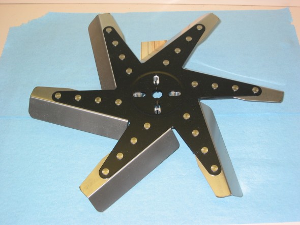
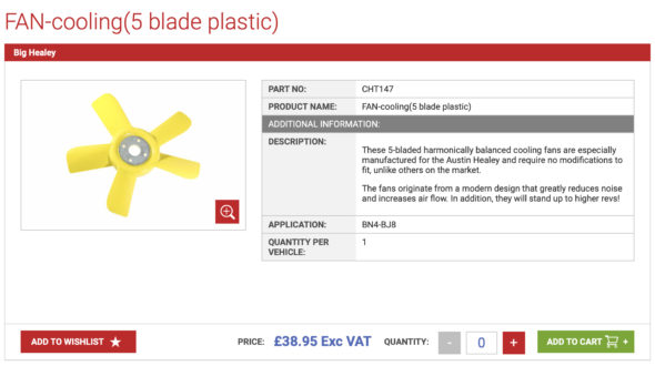
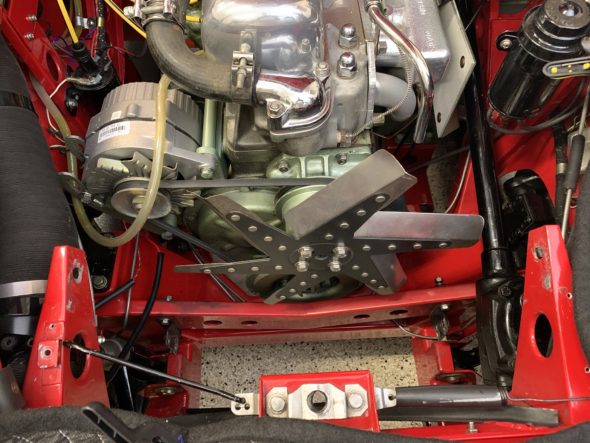
When I restored my car I installed the stainless steel flex fan sold by British Car Specialists. It seemed to work quite well, but was pretty noisy. I noticed that AH Spares was marketing a yellow asymmetrical plastic fan similar to the “Texas Cooler” fan which so many owners seem to favor.

Stainless Fan

Stainless Fan

AH Spares Fan

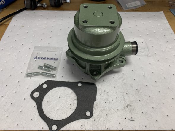
The water pump to be replaced on my car is not the original pump. I am really not sure who produced the pump I used when I restored my car. It does not have any external markings on the pump body. Michael Salter restores original pumps but does not want to deal with replacements so I purchased a newly produced pump marketed by AH Spares which is claimed to be superior to what is commonly available on the market. The pump, as unwrapped, is painted black so I roughed up the painted surface, taped off the vent holes and painted the pump and pulley “Healey Green.” A gasket is applied with the pump. I also ordered new water pump/engine block studs to install.

AH Spares Water Pump, Gasket, and Studs

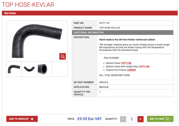
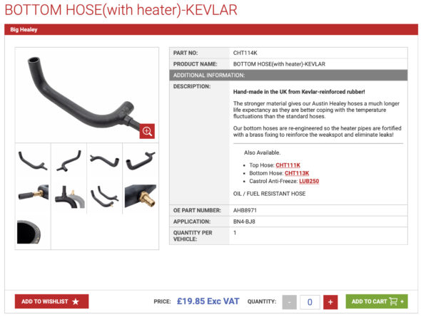
I chose to replace both radiator hoses with Kevlar hoses from AH Spares. The bottom, or lower, Hose has a provision for the heater pipe.

AH Spares Kevlar Upper Radiator Hose

AH Spares Kevlar Lower Radiator Hose With Heater Port

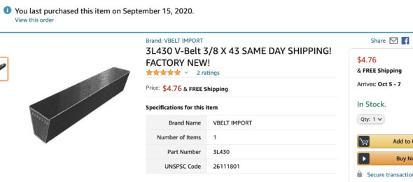
The fan belt is an odd size attributable to the addition of the Delco alternator, but I found one through Amazon from an outfit called Global Power. The belt is a “V” belt 3/8″ x 43.”

Global Power V-belt 3/8 x 43″

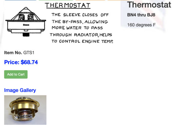
Finally the thermostat. Having lived in Virginia with considerably cooler winter temperatures than Florida, I had been using a 195 degree thermostat. I took this occasion to switch to a sleeved 160 degree unit supplied by David Nock at British Car Specialists.

British Car Specialists Thermostat

That concludes the list of parts used on this project. Now to the removal of the old and the installation of the new!

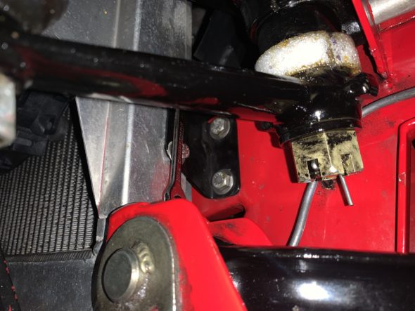
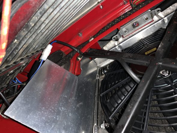
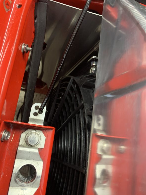
My first step is to remove the stainless panel between the shroud and the radiator. This requires loosening the top radiator mount bolts so the radiator can be pushed rearward slightly. Then disconnect the bonnet pull rod by pulling out the split pin, followed by the four stainless self-tappers.

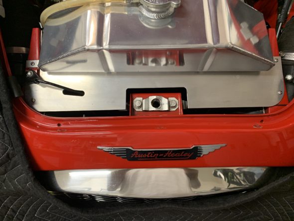
Radiator Front Stainless Panel

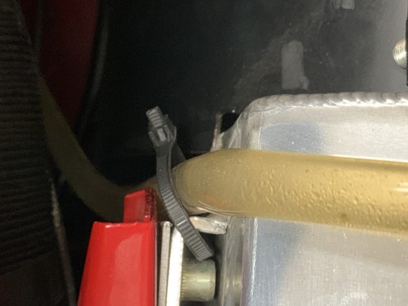
The radiator mounting bolts are metric. 6mm requiring a 10mm wrench. A zip tie is used to secure the coolant overflow tube to the radiator mount so that it cannot foul against the alternator fan.

coolant overflow hose

I then removed the four lower radiator mounting bolts all with 10mm wrench.

Lower Radiator Mounting Bolts

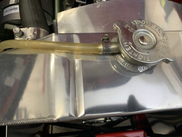
Disconnected the overflow hose from the radiator cap.

Radiator Overflow Tube Clamp at Radiator neck

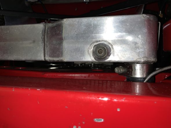
Removed the radiator drain plug with a 6mm hex Allen wrench and drained the coolant from the radiator. With the mounting bolts removed and the coolant drained one can push the bottom of the radiator forward providing easier access to the lower radiator hose clip. I then loosened the clip with a 10mm socket wrench and freed the hose, of course, more fluid drained out.

Radiator Drain Plug 6mm hex

I then loosened the upper radiator hose bracket at the radiator, again with a 10mm socket. To remove the hose I had to loosen the upper mount for the radiator shroud. It is a 10-32 hex head machine screw.

Radiator Hose Clamp for Upper Hose 10mm

I Loosen the hose clamp at the thermostat housing and tilted the hose upward where I will leave it until I replace it with a new hose.

Upper Radiator Hose

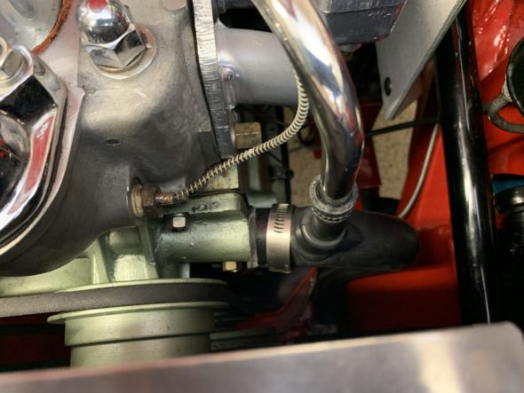
Then I moved on to loosening the clamp on the lower radiator hose for the heater pipe. This clamp requires a 7mm socket. I then loosened the clamp for the lower radiator hose at the water pump  with a 8mm socket.

Lower radiator Hose Clamps

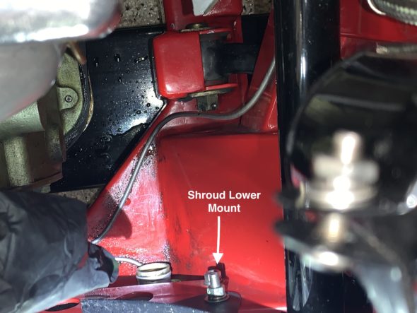
The next step is to remove the lower shroud mounts on both sides of the radiator which is connected to the lower radiator mount. This requires a half inch socket with a long extension for the right side.

Radiator Shroud Lower Mounts

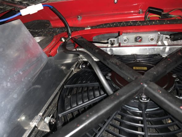
I then disconnected the wiring to the electric radiator fan. This requires unplugging the electrical connector and disconnecting the clamp securing the wire.

Electric fan Wiring Connector

Electric Fan wiring and clip disconnected

I was then able to lift the radiator out from the car as well as the left and right baffles.

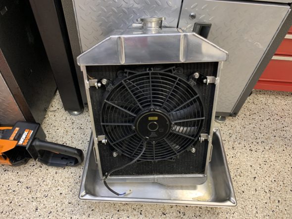
Radiator and Fan Assembly Removed From Car

Engine Bay Sans Radiator and Baffling

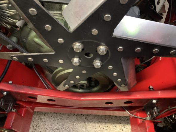
The next step is to remove the engine fan and its spacer. Four bolts with 1/2” wrench.

Engine Fan Mounting

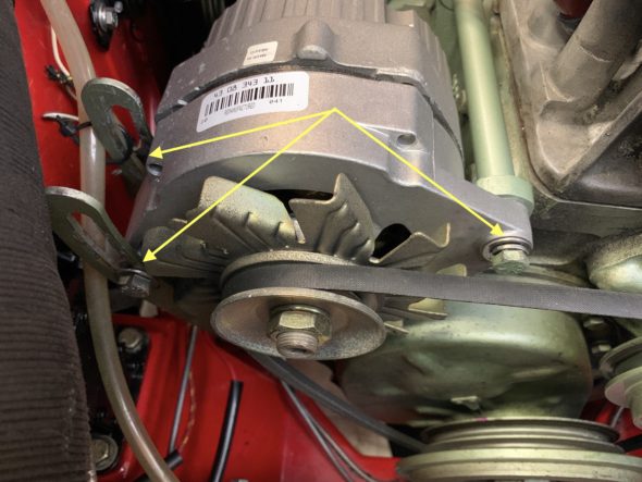
I then needed to take tension off of the fan belt by loosening the alternator swing bracket and locking nut. The locking nut is 13mm while the others are 9/16”.

Alternator loosening points

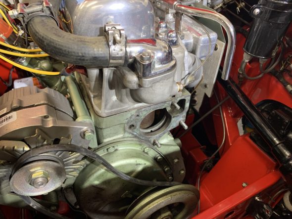
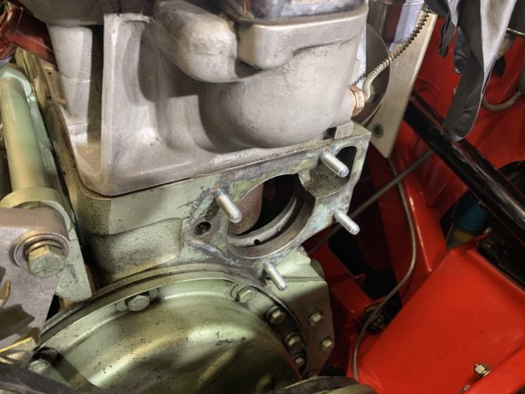
Following removal of the old fan belt, I removed the nuts and split washers on the four water pump studs, gave the pump body a few taps and removed the pump. Again, be prepared for coolant spillage. The lower center nut is a bit hard to access, but it is doable. I then used a blade and some brake cleaner and cleaned up the surface of the block to prepare for the pump gasket.

Water pump removed

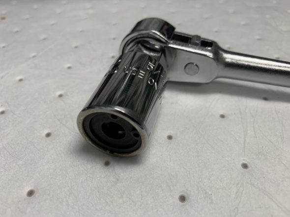
I removed the four water pump studs from the engine using my handy-dandy stud remover which worked beautifully.

5/16″ Stud Removal Tool

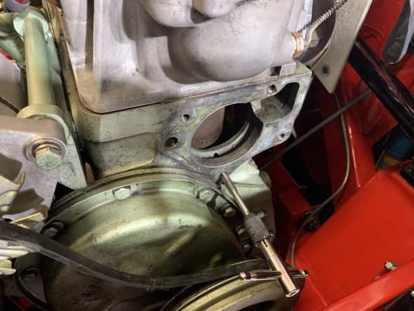
I then chased the threads in the block just to be sure that they were nice and clean.

Cleaning water pump stud threads

Then using the two nut method I installed the new studs with a little blue Loctite on the engine end.

New studs installed with a little blue locktite on the threads of the engine side:

Water Pump Studs Installed

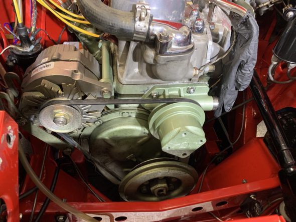
After installing the new water pump using Permatex Water Pump and Thermostat Housing RTV silicone sealant and the new gasket, I then installed a new Gates 43” fan belt and tightened the alternator in place.

Water Pump, Pulley and New fan Belt Installed

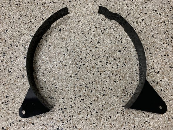
While they were out I freshened up the two pieces of the fan shroud just a little sanding and some fresh paint.

Fan Radiator Shroud Repainted

I then loosely installed the shroud to the frame of the car.

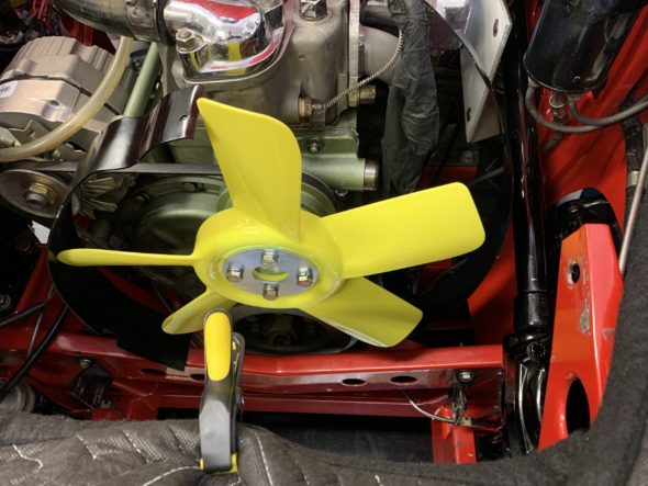
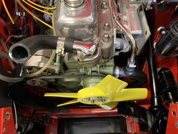
Next was the installation of the new fan from AH Spares with four 5/16-24 x 7/8” hex bolts.

AH Spares Fan Installed

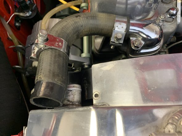
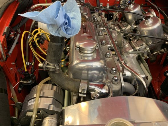
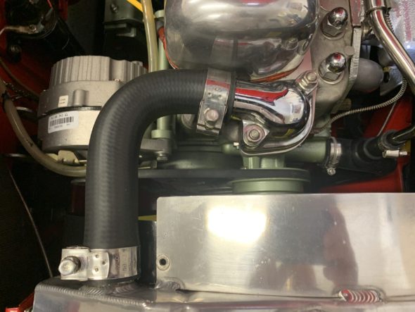
I then installed the new Kevlar radiator hoses. So they are ready to connect to the radiator once in.

New Hoses Installed

I lifted the radiator into position and loosely attached the upper two mounting bolts. I then raised the car on the lift to get to the lower mounting brackets.

I reinstalled the radiator drain plug, connected and clamped the lower radiator hose, and loosely fitted the four screws into the lower brackets.

Then the biggest challenge was to install the two air baffles around the radiator. I installed both from below. Difficult but got them in.

RH Radiator Baffle Installed

I then tightened the heater pipe hose clamp and the clamps for the upper radiator hose and the water pump hose. These need to be pretty tight to be effective and eliminate leaks!

Hose Clamps Installed and Tightened

I then raised the car and from the underside reconnected the electric fan and tightened the four lower radiator mount bolts.

Electric Fan Wiring Reconnected

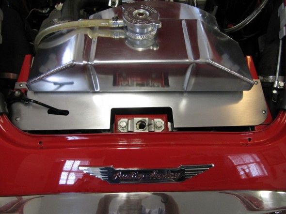
I then purchased some new tubing from the local hardware store for the overflow hose to the radiator neck, installed the aluminum cover panel, and reconnected the bonnet opening rod lever.

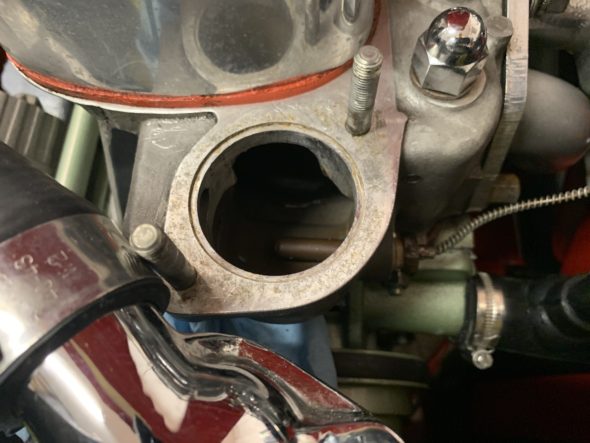
I then backed up a bit and loosened the two nuts and lock washers on the thermostat cover and lifted it away from the head. I removed the old thermostat and cleaned up the mating surface on the head and the cover to prepare for the new gasket.

Thermostat seating in the cylinder head.

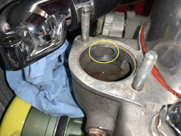
I decided to use a sleeved thermostat this time around to try to enhance cooling functionality. The following photo shows the hole in the cylinder head permitting recirculation of engine coolant to the engine. The sleeve of the thermostat blanks off the opening until the thermostat opens and coolant from the radiator is introduced to the system.

Coolant bypass opening circled

I again used Permatex Water Pump & Thermostat Housing RTV silicone on both surfaces of the gasket and installed the gasket and thermostat. I then tightened the two split washers and nuts and cleaned up around the edges where the sealant pushed out of the joint.

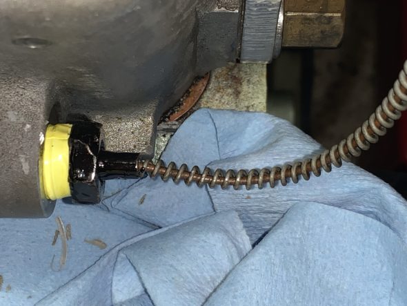
I decided while I was at it that I would check the accuracy of my dash fascia temperature gauge so I unscrewed the sensor from the head, freed the capillary tube from its two holders and put it in hot water and measured the temperature. While it didn’t exactly match the thermometer I was using in the hot water it was within a few degrees so I felt good about the accuracy of my gauge. I then put a little paint on the nut and reinstalled the sensor to the head using some yellow plumbers tape intended for oils.

coolant temperature sender reinstalled

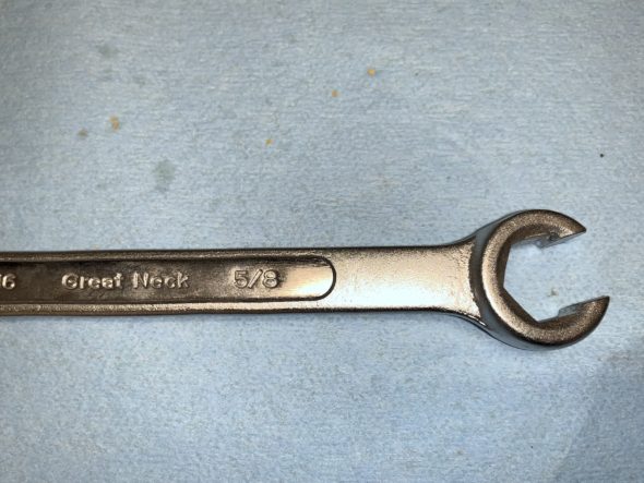
The sensor nut is hard to access. I used a flare wrench to do the job.

Flare Wrench 5/8″

After buttoning everything up, I took the car out for a short trip around the block and then inspected the engine bay to make sure that I had no coolant leaks. Having none, I then went out for about a thirty minute drive to “heat-soak” the engine. All systems were “go” with no problems and the engine getting no hotter than about 165 degrees. 

Kent Lambert in Oregon located an original proper water pump (AEC206), pulley, key, lock washer and nut for me. It requires rebuilding so I have sent it to Michael Salter in Canada to have that job completed. I will then keep it as my spare water pump for the future! Thank you Kent and Michael.

Another ten-year renewal job checked off the list!


Cooling/Heater

Managing the heat generated by the operating engine, whether in the engine itself, in the engine bay, or in the interior is an issue in the Big Healey. What may not have been an issue in more temperate Great Britain, is a different story in the U.S. Over the years Healey owners have gotten progressively better at managing the heat issues. I made a number of enhancements to The Bloody Beast to help with cooling or at least improved insulation from the heat.

 The Original Cooling System

The capacity of the cooling system, excluding the heater, is 21.6 U.S. pints. The original thermostat was 158 degrees.

Cooling System Modifications

Aluminum Radiator

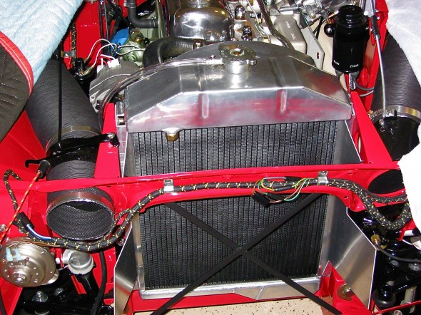
Recoring the original radiator with a more efficient tubing system is one option pursued by many enthusiasts, another is replacement of the original radiator with an aluminum alternative.  I chose the replacement route with an alloy radiator sourced from Cape International. In addition to the benefit of improved cooling, the polished aluminum header tank looks great in the engine bay! I painted the core with black radiator paint so that the “X” brace in the front of the car would “disappear” when looking through the grille.

Aluminum Radiator

Aluminum Radiator

Air-Intake Deflectors

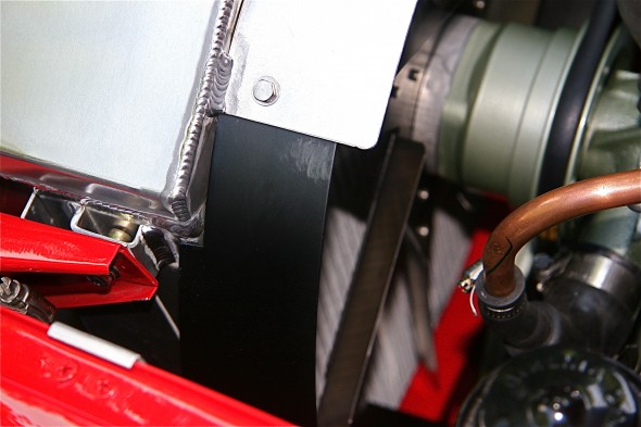
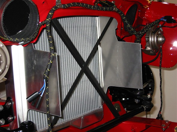
The Healey has a multi-piece air-intake deflector assembly as original equipment; however, I was not happy with the gap that exists between the assembly shrouds and the radiator. This permitted air to escape around the radiator into the engine bay. The original deflectors are also a bit of a pain to install. I decided to fabricate some deflectors from aluminum stock. After constructing cardboard patterns I had the aluminum bent at a metal working shop. The deflectors are slotted to fit alongside the radiator in the standard radiator mounts to the frame. The image below shows the fitting of the deflectors before the radiator core was painted. As you can see this produced a tight fit around the radiator sides – no air escapes now!

Radiator Baffles

Radiator Baffles

Upper Radiator Shroud

My friend, Mick Nordquist, had an upper shroud made for his Healey radiator to keep the air coming through the grill directed to the radiator rather than escaping over the radiator. He supplied the pattern for me and I had one cut with a plasma cutter from 2mm aluminum plate and installed it with four stainless steel #8 self-tapping screws. In addition to improving cooling, I think it also offers a nice cosmetic improvement.

Radiator Top Shroud

Radiator Top Shroud

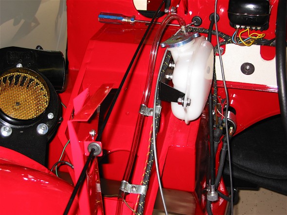
Coolant Recovery System

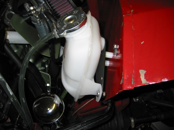
The original cooling system design provided for no ability to capture coolant whether just an expansion tank or a true pressurized recovery system. Healay owners, particularly if they have filled their radiators to maximum capacity are use to their car’s “burping” in the parking lot after being driven. I purchased my coolant recovery system components from Cape International.

Coolant Recovery System

Coolant Recovery System

Six Blade Stainless Steel Fan with Spacer

A number of alternatives to the original fan are available to the Healey owner today. The “Texas Cooler” and the variable pitch stainless steel fans are probably the most popular. I initially decided to go with the stainless fan available from British Car Specialists. However, the fan is pretty noisy so I switched the fan in 2020 for a nylon/plastic asymmetric fan similar to the “Texas Cooler” fan. The new fan was sourced from AH Spares. Time will tell but the new fan seems to keep the engine temperature under control and it is quite a bit quieter than the stainless steel fan.

Stainless Fan

Stainless Fan

AH Spares Fan

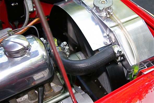
Fan Shroud

The custom air deflectors improved air control on the intake side of the radiator. To help channel the air on the fan side of the radiator and to add a safety component (those stainless fan blades are very sharp!!) I added a two piece shroud also available from British Car Specialists. It did not fit exactly as it would to the stock radiator, but a little tinkering and it fit beautifully. Since it was added after the restoration of the Bloody Beast was completed, I can say that the shroud was definitely responsible for some additional temperature reduction.

Radiator Shroud

Radiator Shroud

Radiator shroud

Radiator shroud

The Original Heater/Interior Cooling

The original heater was a Smith’s hot water circulating unit, part # 8G9048. It was assisted by a fan blower secured to the right front wheel arch assembly. Fresh air was supplied to the driver’s side of the interior by a 4” paper/metal hose controlled by a fresh air assembly mounted at the front of the car.

Heater/Interior Cooling Modifications

Sealing all of the holes in the firewall is the first thing to be done if one is to keep the heat and fumes out of the interior. A helpful tip someone shared with me was to wait until dark and put a light in the engine bay. This way any holes or leaks can be easily spotted from the interior.

Dynamat Extreme and Aluminum Duct Insualtion

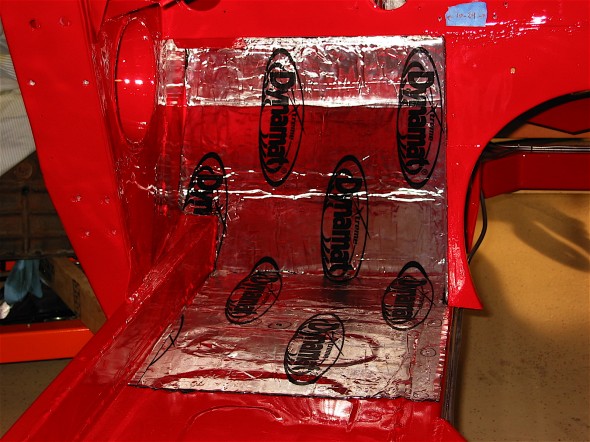
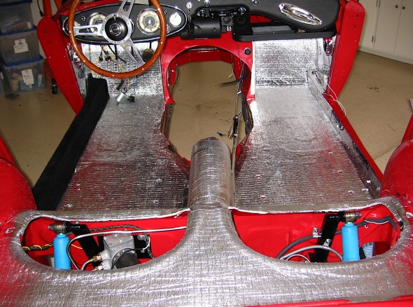
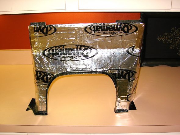
A number of products are on the market to help reflect heat and offer both heat and sound insulation. Dynamat Extreme is certainly on of the most popular. I applied Dynamat Extreme heat reflective and sound insulation material to my interior first. I then applied aluminum duct insulation on top of the Dynamat and under the carpet. All seams were sealed with aluminum tape. These two together have proven to be very effective in keeping the heat out!
Dynamat Extreme

Dynamat Extreme

Aluminum Duct Insulation

Aluminum Duct Insulation

Modern Heater

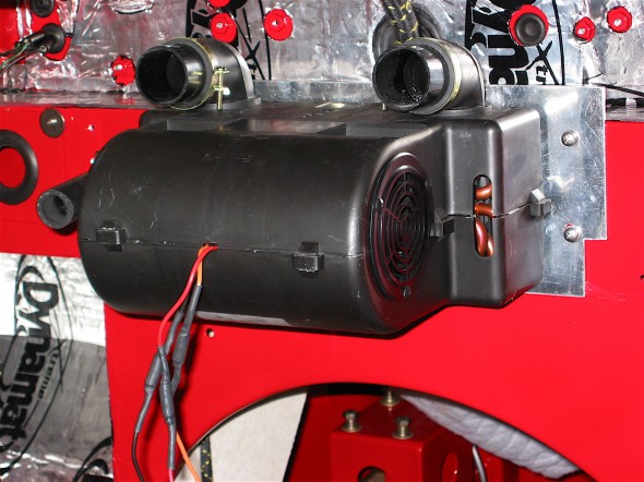
For those (rare) occasions when I would choose to have more heat in the interior spaces, I chose to replace the Smith’s Heating unit with a contemporary unit supplied by Cape International. This unit has an internal two speed fan.

Cape International Heater

Cape International Heater

Fresh Air Supply

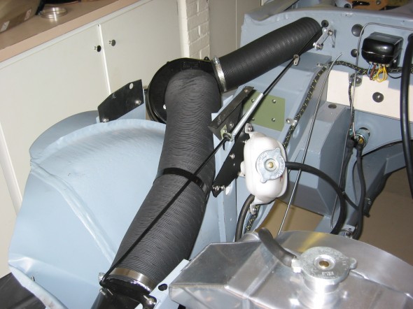
The original design of the car provided for some fresh air being delivered to the LH driver’s side of the car. Given that the Cape International Heater has its own fan, that left the original Smith’s blower to be used to blow fresh air into the passenger side of the car. I installed an air intake valve (upside down) just like the one on the LH side of the car, on the RH side, and then wired the blower to provide fresh air on the passenger side when desired. To be honest, I have found this to be useful for some ventilation when one has the hardtop in place, otherwise I am not sure that it was worth the effort! There are more details about this project in the restoration blog.
Ventilation Hose Assembly

Ventilation Hose Assembly

zz

Chapter 76 Week Forty-Six October 29, 2007

I am not quite ready to start the engine because I am waiting on my custom made propshaft, currently being fabricated by Dale Engineering. However, there were some close to final matters that needed attention as the day to fire up the engine approached. Jack Harper from Coachworks, Ltd. who assembled my rebuilt engine, came to the house to assist with readying the engine.

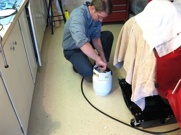
Our first step was to “pump” some engine oil into the engine to ensure that everything was coated. Jack attached a compressed air canister with two quarts of oil to the oil pressure pipe union and then forced the oil into the engine with air pressure. As we neared the end of the oil transfer one could see the oil emerging from the top of the rockers and then the end of the transfer was signaled by a large “burp” that one could easily hear.

Jack Harper engine oil

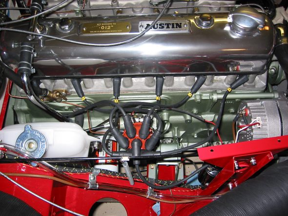
We made sure the pointer and timing mark were aligned and then went about checking the valve gap for the assembly. I used the starter to turn over the crank as we checked each rocker/valve. We then secured the Capesport Alloy rocker cover and added another 5 quarts of oil. The rocker cover was sourced from Cape International.

Capesport Rocker Cover & Ignition Wiring

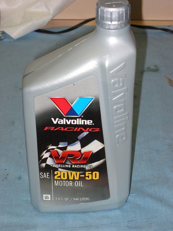
The oil I chose to use is Valvoline racing oil, 20-50 with ZDDP.

Valvoline 20-50 Oil

I had taken the NGK spark plugs out to rotate the engine. We put a little anti-seize on each plug, checked the gap and re-installed each one.

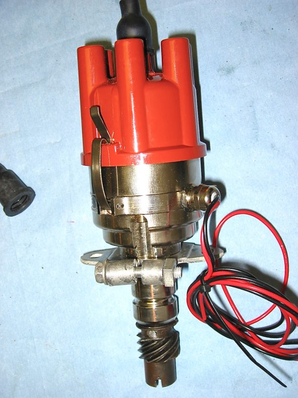
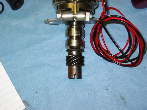
In recent months the 123 distributormanufactured by a Dutch company, 123 Ignition, has received some very good press. I had originally planned to use a Mallory Unilite distributor, but I decided to give the 123 unit a try.  One appealing aspect of the 123 is that the advance curve is determined by simply adjusting the settings by turning an adjustment on the outside of the distributor and “clicking” it into place. For initial set-up, I chose the recommended “B” setting. While the distributor is a “drop-in” in for the BJ8 with an electronic tach, a kit is supplied to adapt it for the mechanical tach drive of the BT7. The shaft did need to be drilled and the drive dog from the original Lucas unit installed with a few spacing washers. My unit was supplied by a German vendor Brits’N’Pieces. Jack installed the distributor and I installed the Pertronix igntion wiring to the plugs and to the Pertronix “Flamethrower” coil. The coil was previously mounted vertically on the shroud brace. Several of the wiring leads on the original wiring harness for the ignition were no longer needed so I simply used plastic ties to fold them down and secure them, in case they might be needed at some point in the future.

123 Distributor

123 Distributor drive dog

123 Distributor.  Purchase Information and instructions.

My next step was to add coolant to the radiator. I used Prestone 50/50 premixed formula. Fortunately no leaks!

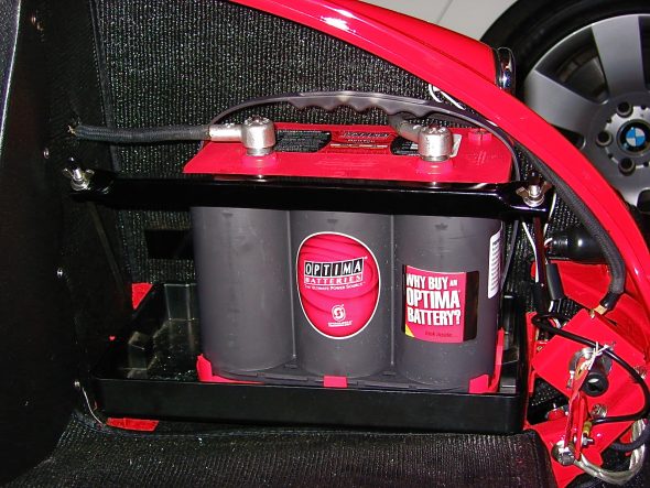
I had been using an old battery for checking out electrical function throughout the restoration process, but it was now time to buy the battery I would be using in the vehicle when it was a road car and not a garage car! I decided on the Optima. I purchased it at the local Batteries Plus store. They are not cheap at about $160 dollars, but I like the idea of the no-leak gel in the boot of a car. The model number I purchased was: Part Number: 34 (8002-002) RedTop®; Battery; Group 34; Cold Crank Amps 800; Crank Amps 1000; Reserve Capacity 110; Ampere Hour 50; Top Terminal; L-10 in.; W-6 7/8 in.; H-7 13/16 in.; UNBOXED. The battery was secured in place with the battery fixing bar and rods.

Optima Battery

Because the Smitty Bell housing fit a little high in my car????, I custom fabricated a gearbox cover extension to provide a little more room for the housing. This also required custom fitting carpet. I had ordered a couple of extra yards of carpet when I ordered my interior from Heritage Upholstery and Trim for this purpose. I first covered both sides of the cover with Dynamat Extreme and then cut and glued the carpet to the cover.

Gearbox cover extension 1

To assist with interior cooling and weight, I ordered a fiberglass gearbox and propshaft cover from British Car Specialist. The original cover was metal and mine was too far gone from rust. Using a fiberglass cover also made it easy to fill the original hole for the side shifter and cut a new hole in the center for the Toyota gear shift. I used an MGB trim ring and rubber seal for the gear shift lever sourced from Moss Motors. Using a helpful hint from Doug Reid, “Mr. Finspanner,” some JB Weld was used to glue four “T” nuts to the bottom of the fiberglass cover so that machine screws could be used to mount the ring, rather than sheet metal screws that overtime would fail to secure tightly in the fiberglass. 

Coolant Recovery System

Coolant Recovery System

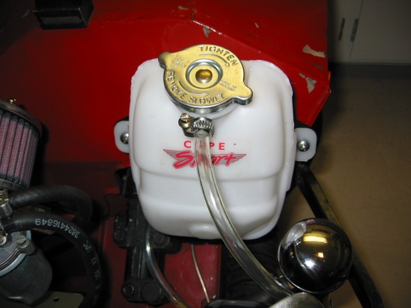
To help with water temperature cooling we decided to add a coolant recovery tank. Purchased a tank from Cape International. Installed it on the left front inner fender in the engine compartment. A new clear hose was used to connect the radiator to the coolant tank and the original drain hose was used to provide a line from the coolant tank. The drain line was run through the clips on the side of the radiator.

Coolant Tank

Coolant Tank

Coolant Tank Mount

Coolant Tank Mount