Managing the heat generated by the operating engine, whether in the engine itself, in the engine bay, or in the interior is an issue in the Big Healey. What may not have been an issue in more temperate Great Britain, is a different story in the U.S. Over the years Healey owners have gotten progressively better at managing the heat issues. I made a number of enhancements to The Bloody Beast to help with cooling or at least improved insulation from the heat.
The Original Cooling System
The capacity of the cooling system, excluding the heater, is 21.6 U.S. pints. The original thermostat was 158 degrees.
Cooling System Modifications
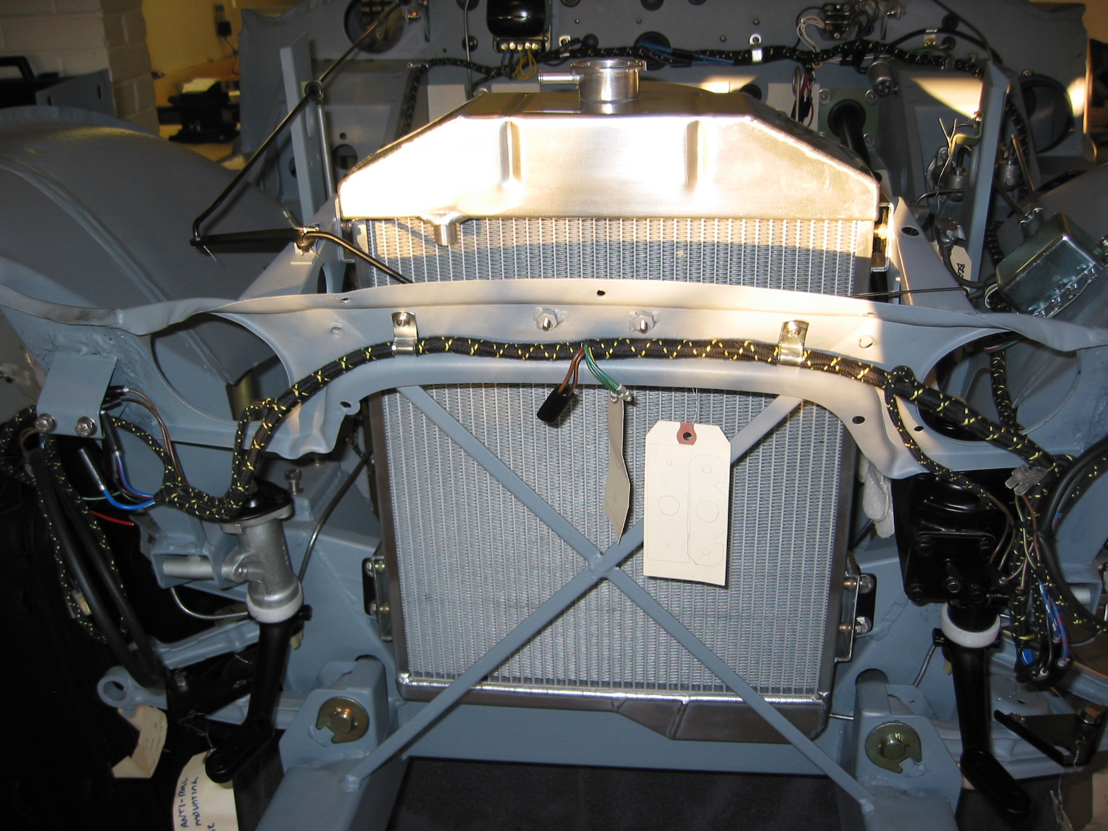
Aluminum Radiator
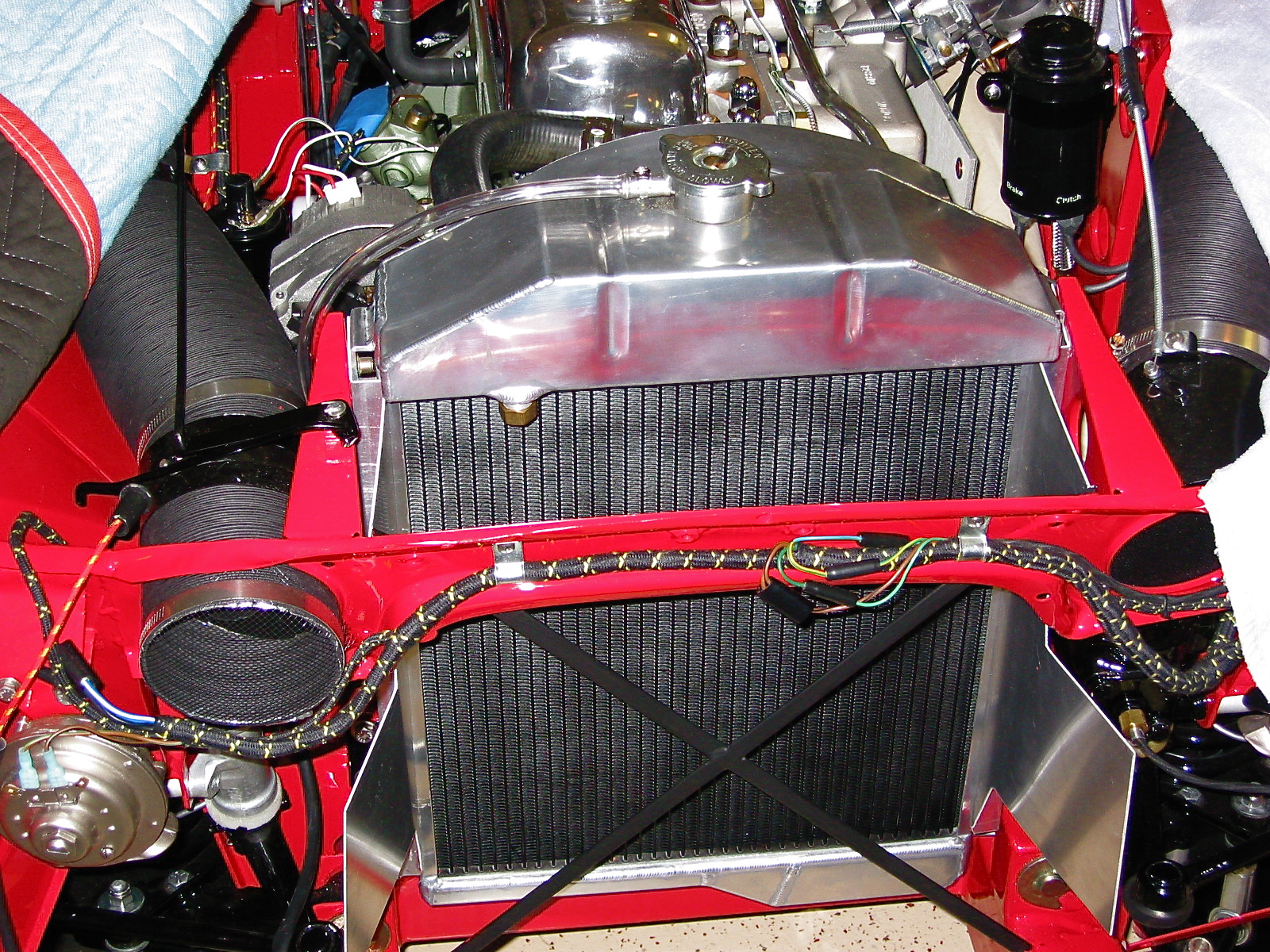
Recoring the original radiator with a more efficient tubing system is one option pursued by many enthusiasts, another is replacement of the original radiator with an aluminum alternative. I chose the replacement route with an alloy radiator sourced from Cape International. In addition to the benefit of improved cooling, the polished aluminum header tank looks great in the engine bay! I painted the core with black radiator paint so that the “X” brace in the front of the car would “disappear” when looking through the grille.

Aluminum Radiator
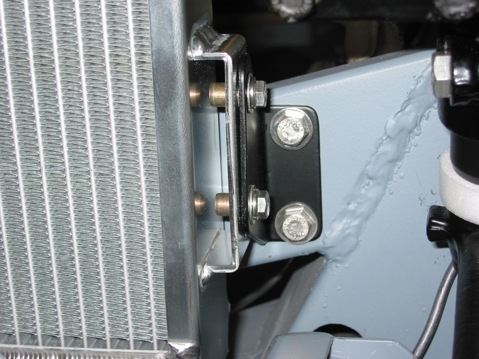
Air-Intake Deflectors
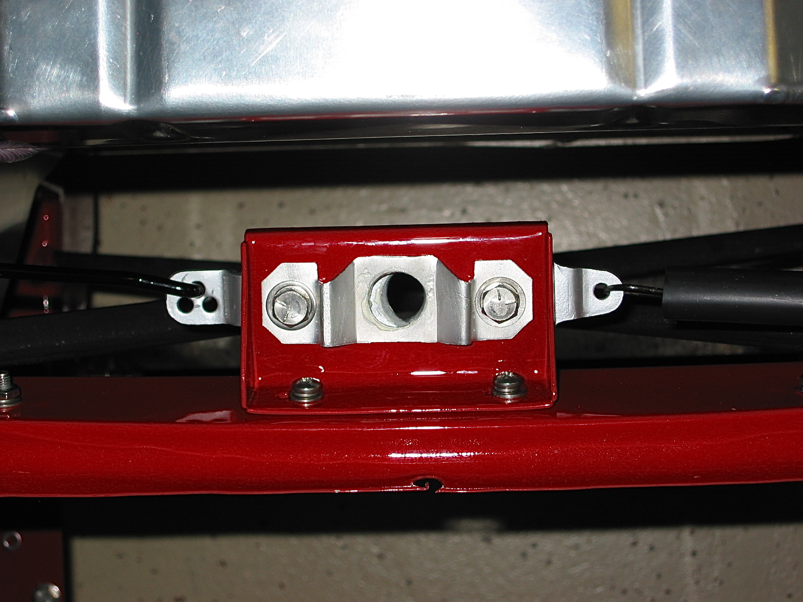
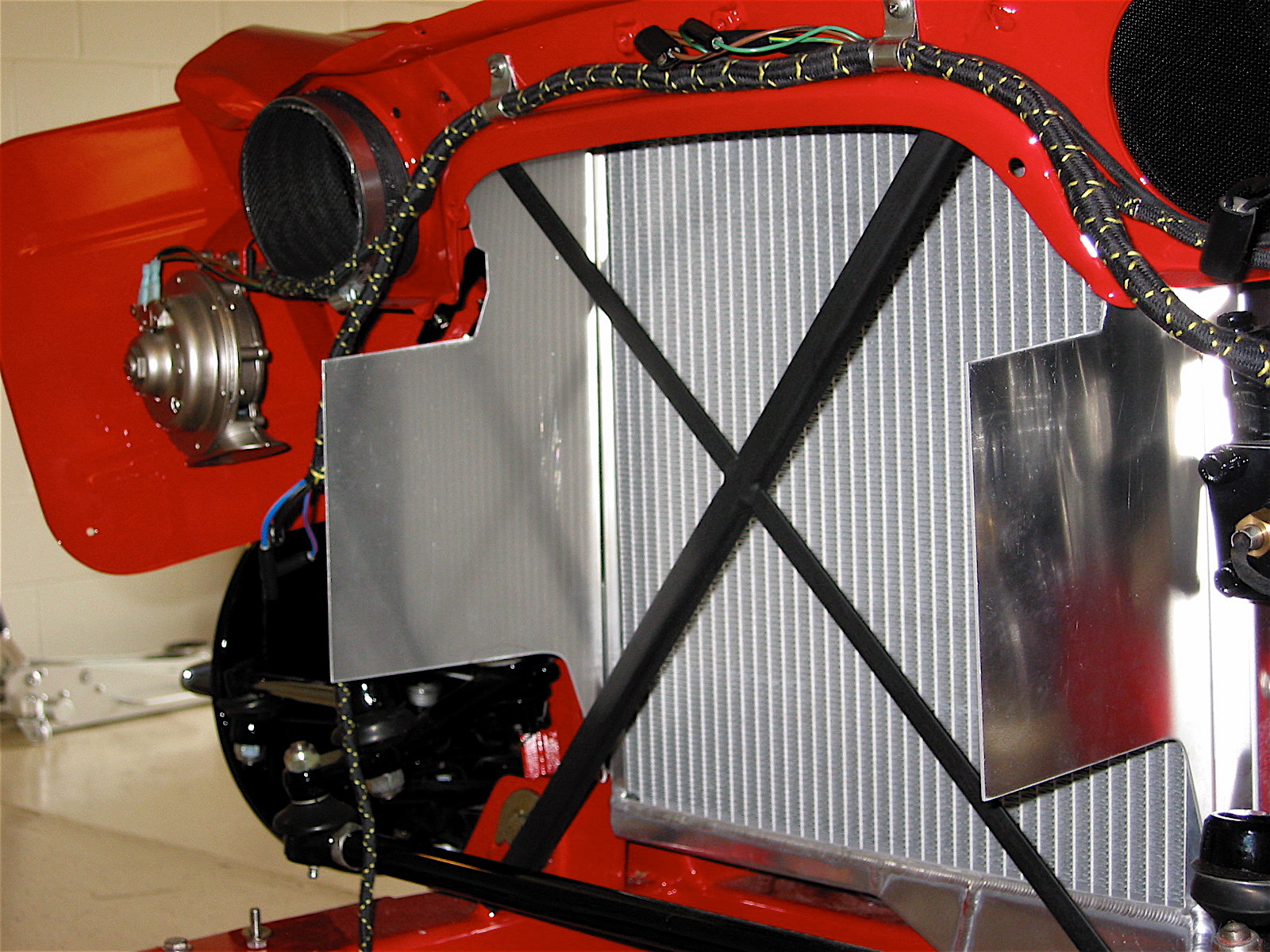
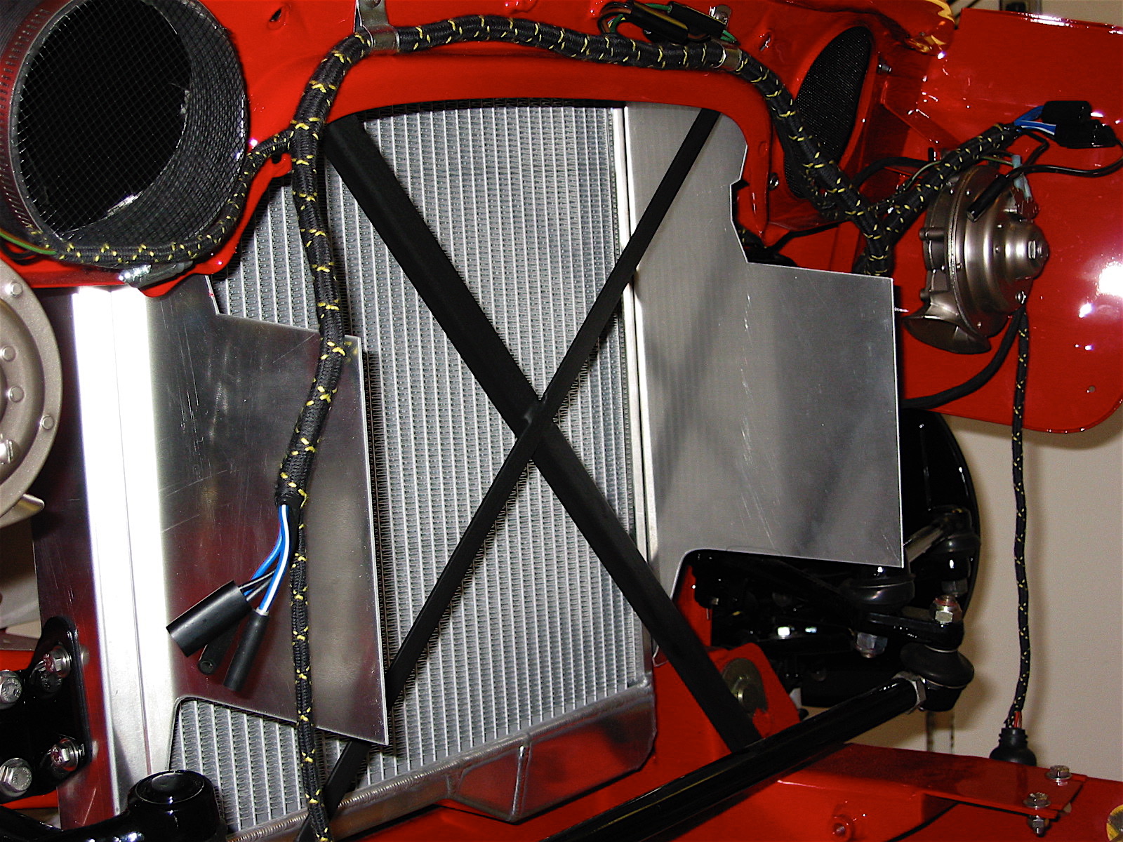
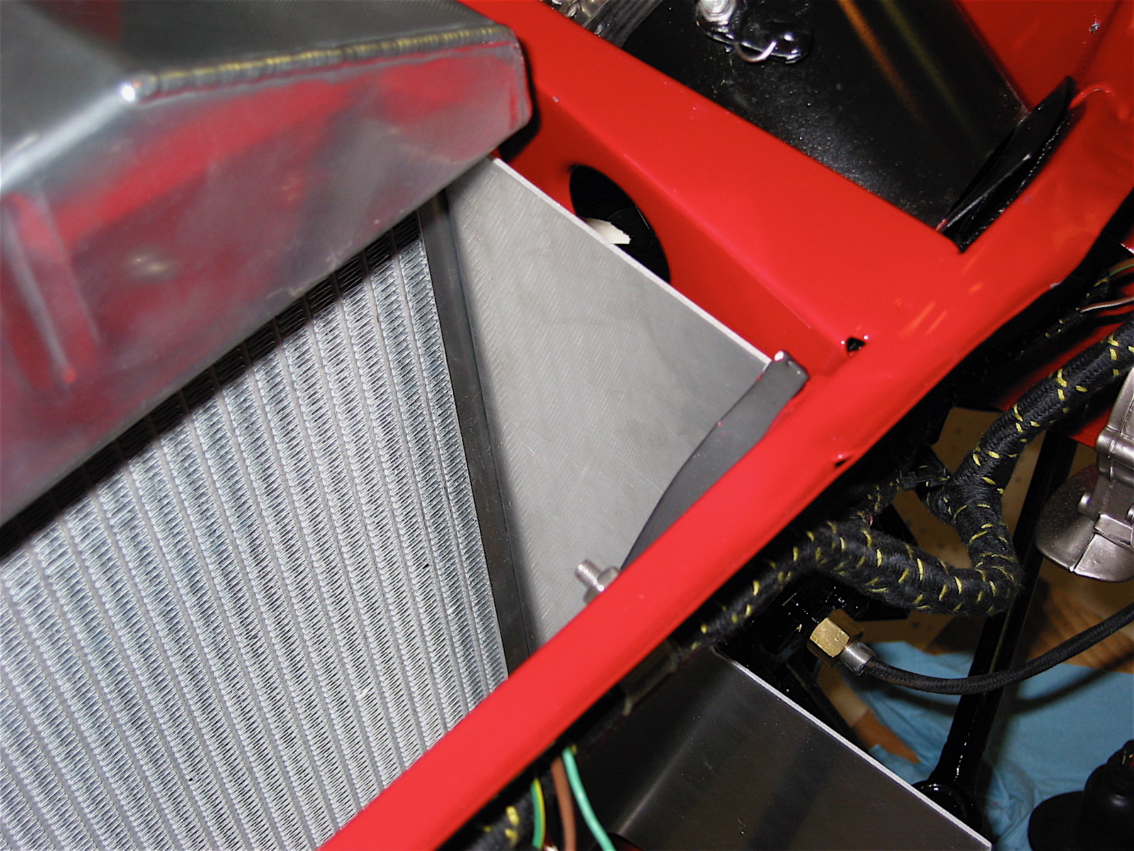
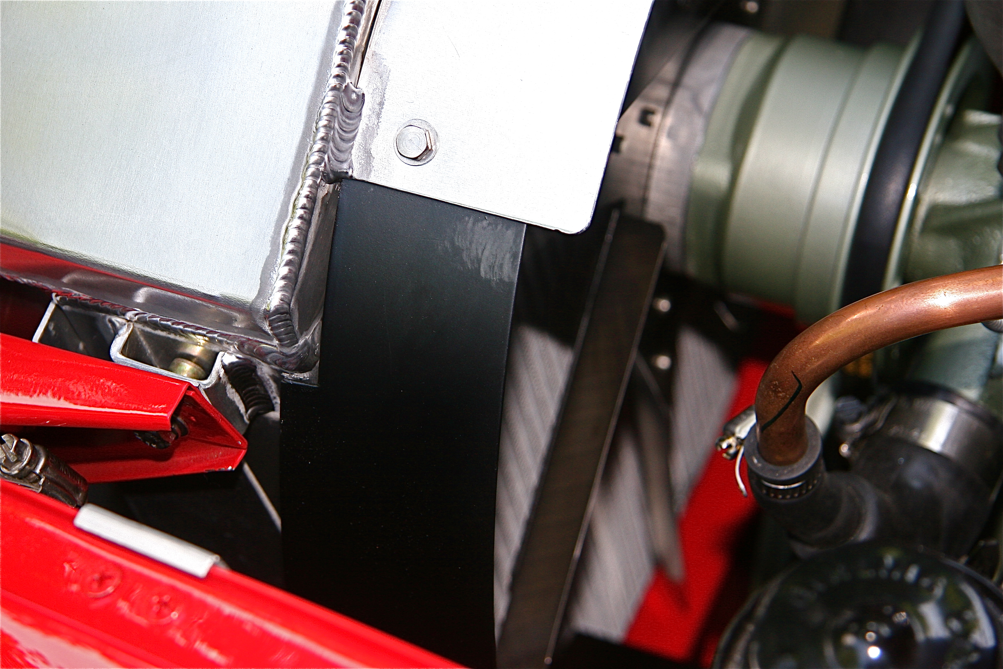
The Healey has a multi-piece air-intake deflector assembly as original equipment; however, I was not happy with the gap that exists between the assembly shrouds and the radiator. This permitted air to escape around the radiator into the engine bay. The original deflectors are also a bit of a pain to install. I decided to fabricate some deflectors from aluminum stock. After constructing cardboard patterns I had the aluminum bent at a metal working shop. The deflectors are slotted to fit alongside the radiator in the standard radiator mounts to the frame. The image below shows the fitting of the deflectors before the radiator core was painted. As you can see this produced a tight fit around the radiator sides – no air escapes now!

Radiator Baffles
Upper Radiator Shroud
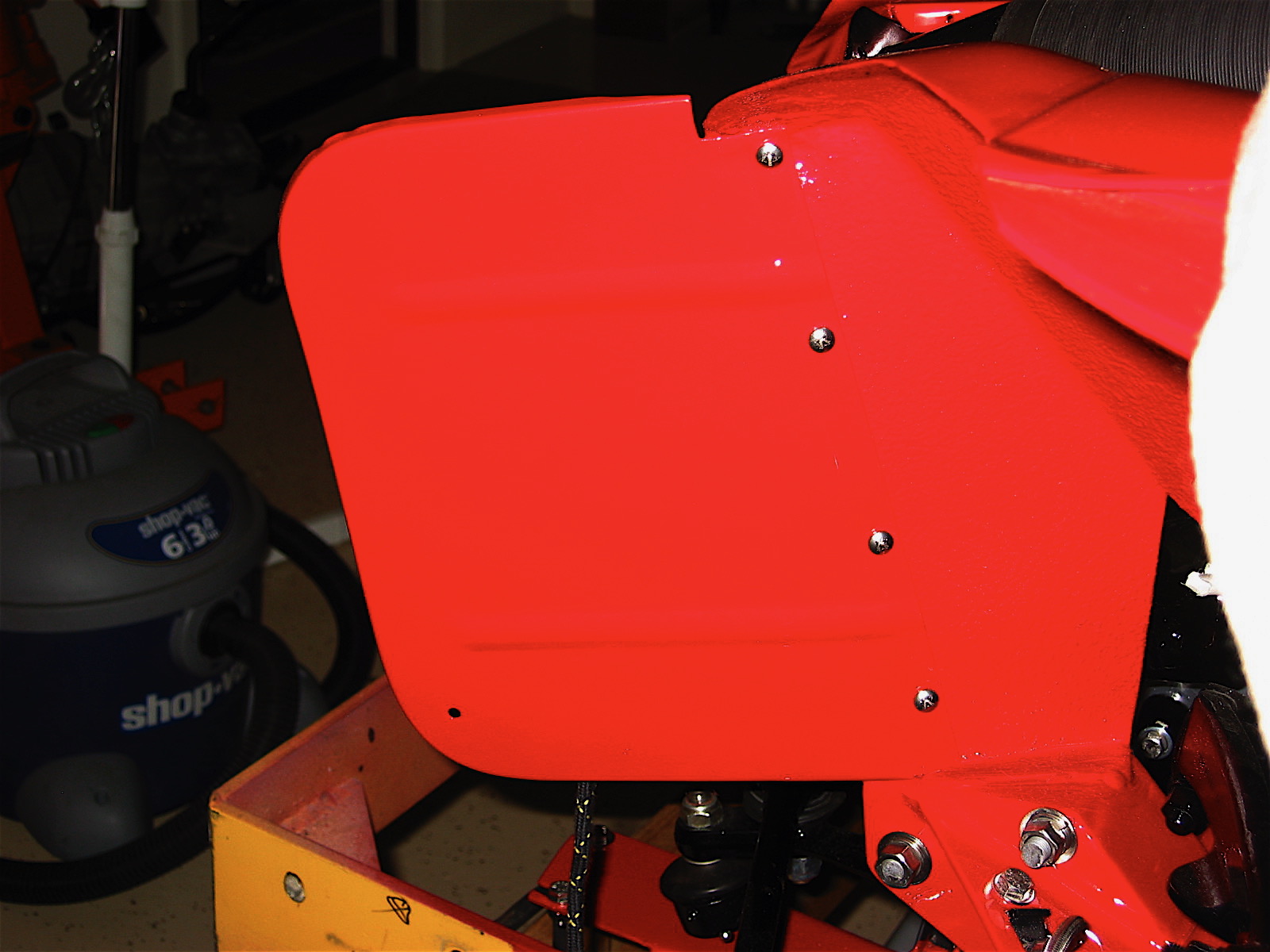
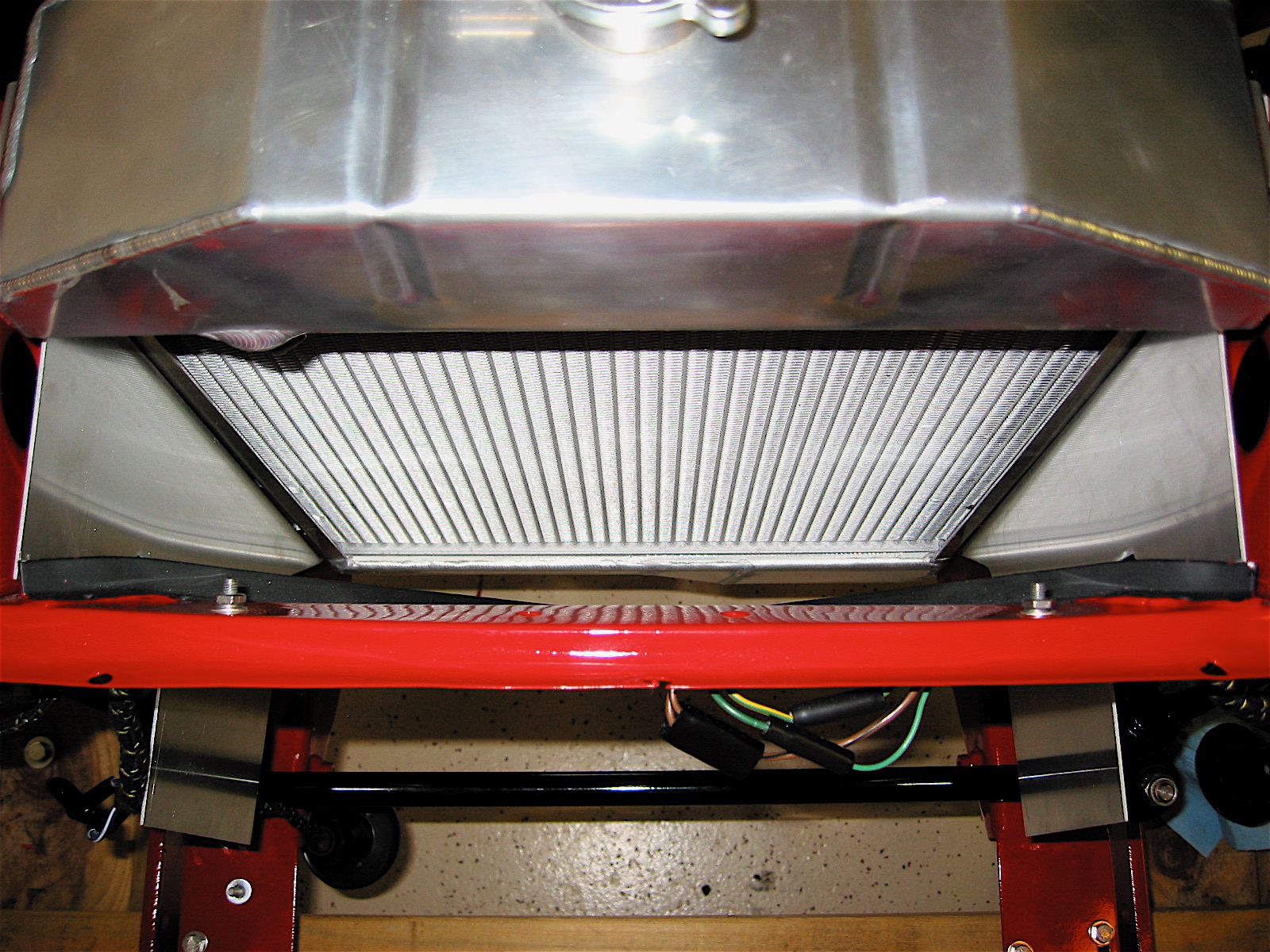
My friend, Mick Nordquist, had an upper shroud made for his Healey radiator to keep the air coming through the grill directed to the radiator rather than escaping over the radiator. He supplied the pattern for me and I had one cut with a plasma cutter from 2mm aluminum plate and installed it with four stainless steel #8 self-tapping screws. In addition to improving cooling, I think it also offers a nice cosmetic improvement.
Radiator Top Shroud
Coolant Recovery System
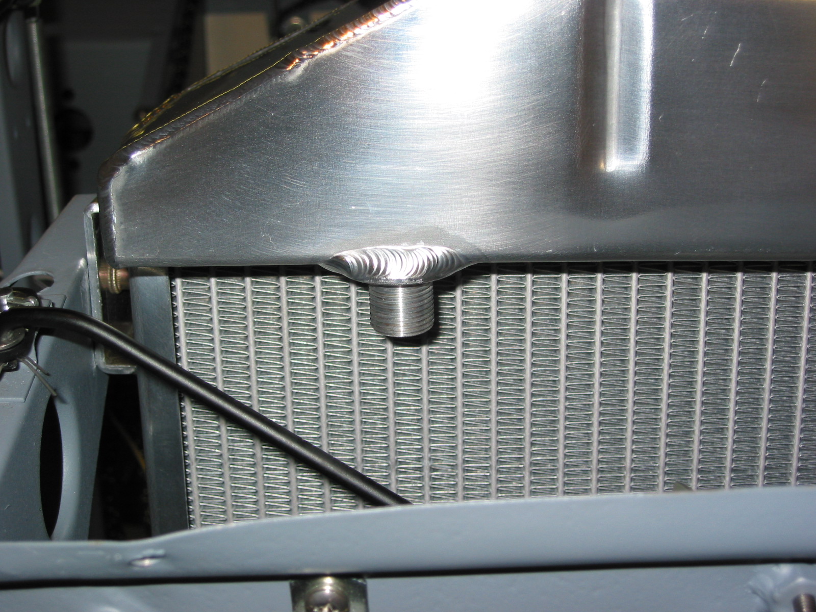
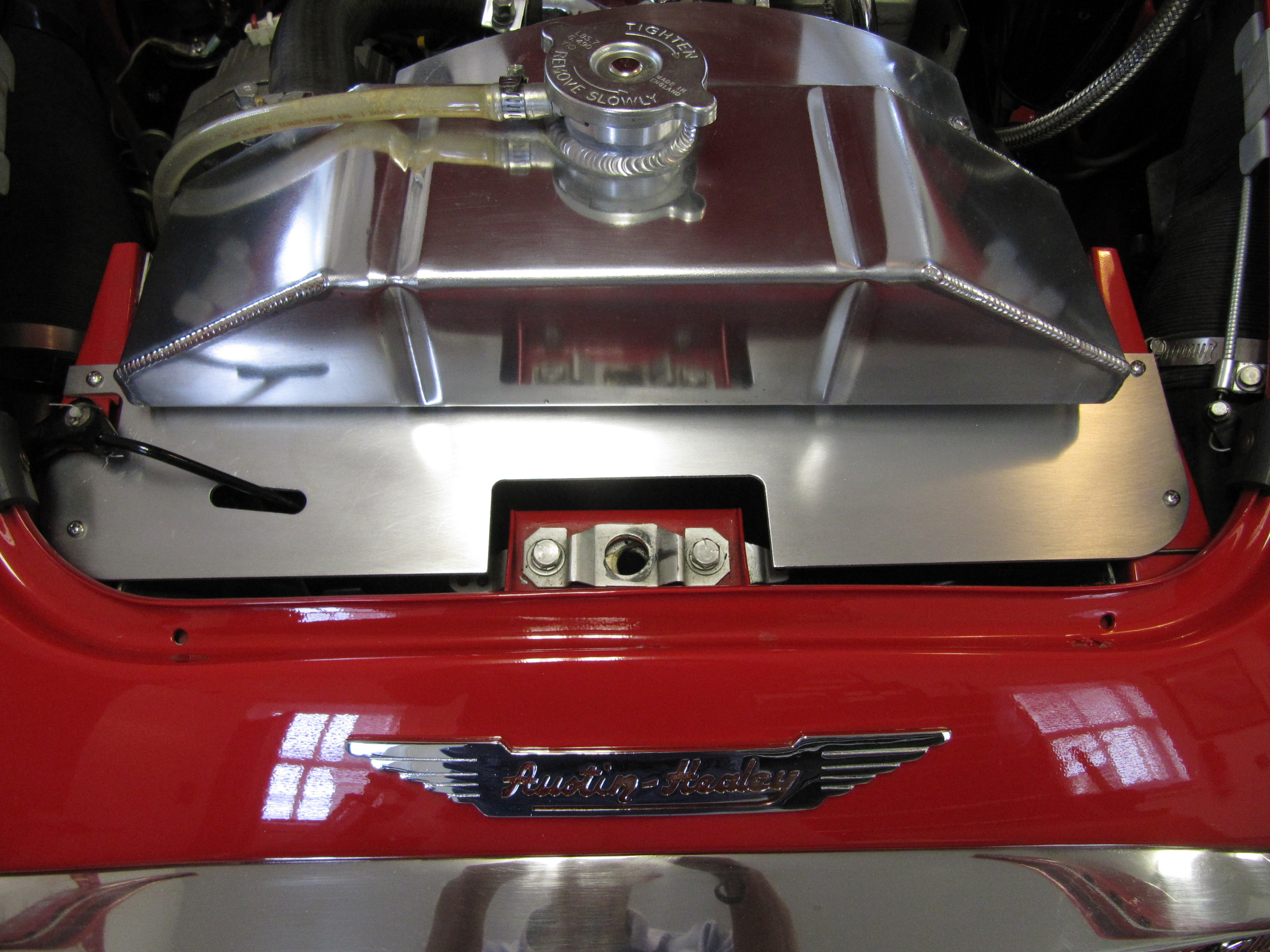
The original cooling system design provided for no ability to capture coolant whether just an expansion tank or a true pressurized recovery system. Healay owners, particularly if they have filled their radiators to maximum capacity are use to their car’s “burping” in the parking lot after being driven. I purchased my coolant recovery system components from Cape International.

Coolant Recovery System
Six Blade Stainless Steel Fan with Spacer
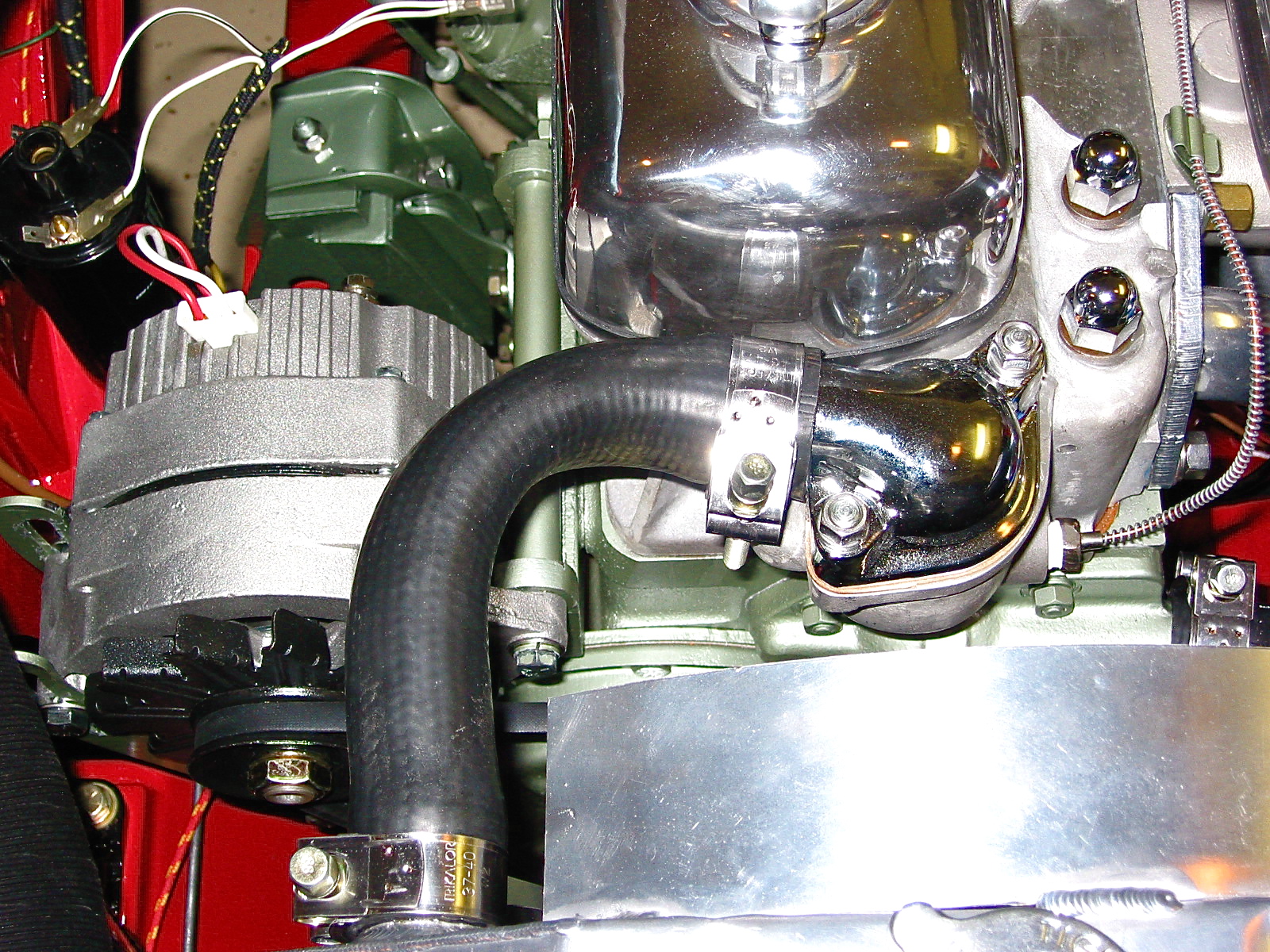
A number of alternatives to the original fan are available to the Healey owner today. The “Texas Cooler” and the variable pitch stainless steel fans are probably the most popular. I initially decided to go with the stainless fan available from British Car Specialists. However, the fan is pretty noisy so I switched the fan in 2020 for a nylon/plastic asymmetric fan similar to the “Texas Cooler” fan. The new fan was sourced from AH Spares. Time will tell but the new fan seems to keep the engine temperature under control and it is quite a bit quieter than the stainless steel fan.

Stainless Fan
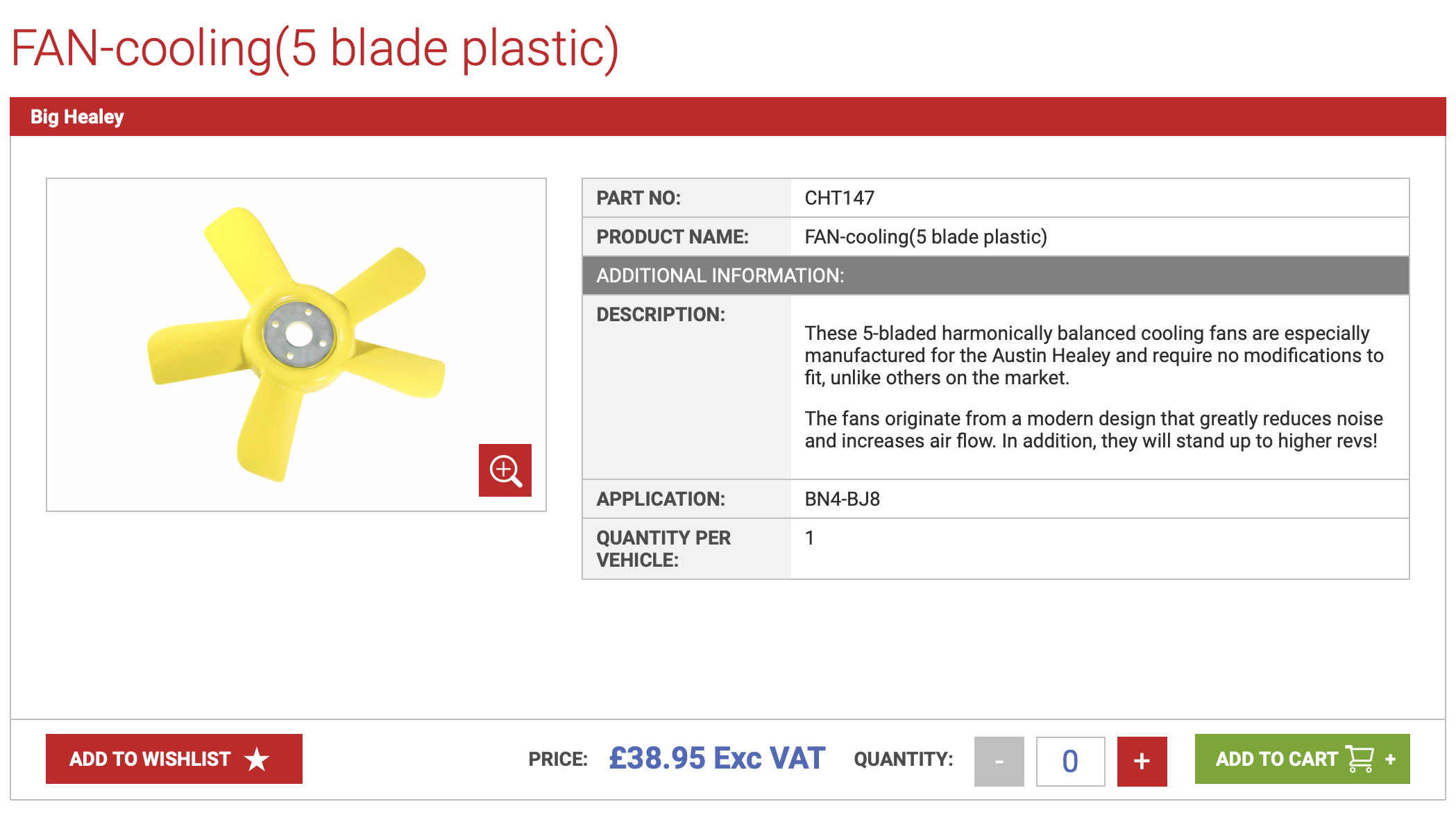
AH Spares Fan
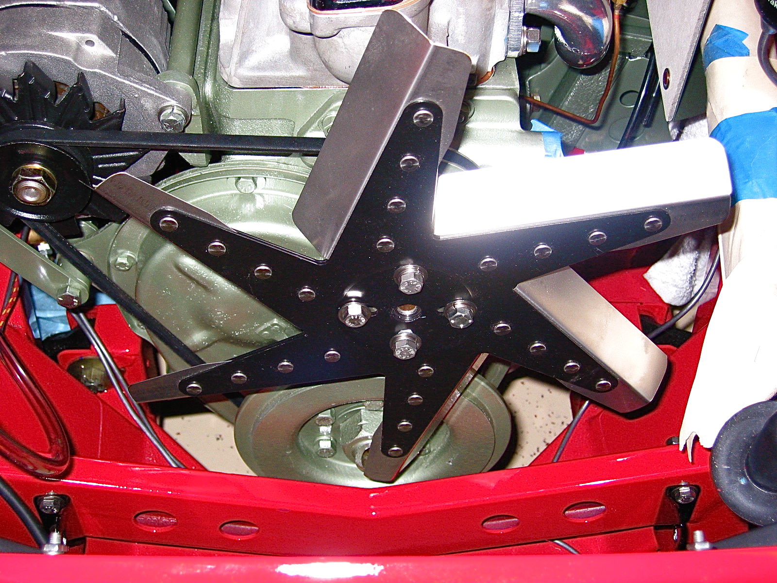
Fan Shroud
The custom air deflectors improved air control on the intake side of the radiator. To help channel the air on the fan side of the radiator and to add a safety component (those stainless fan blades are very sharp!!) I added a two piece shroud also available from British Car Specialists. It did not fit exactly as it would to the stock radiator, but a little tinkering and it fit beautifully. Since it was added after the restoration of the Bloody Beast was completed, I can say that the shroud was definitely responsible for some additional temperature reduction.
Radiator Shroud
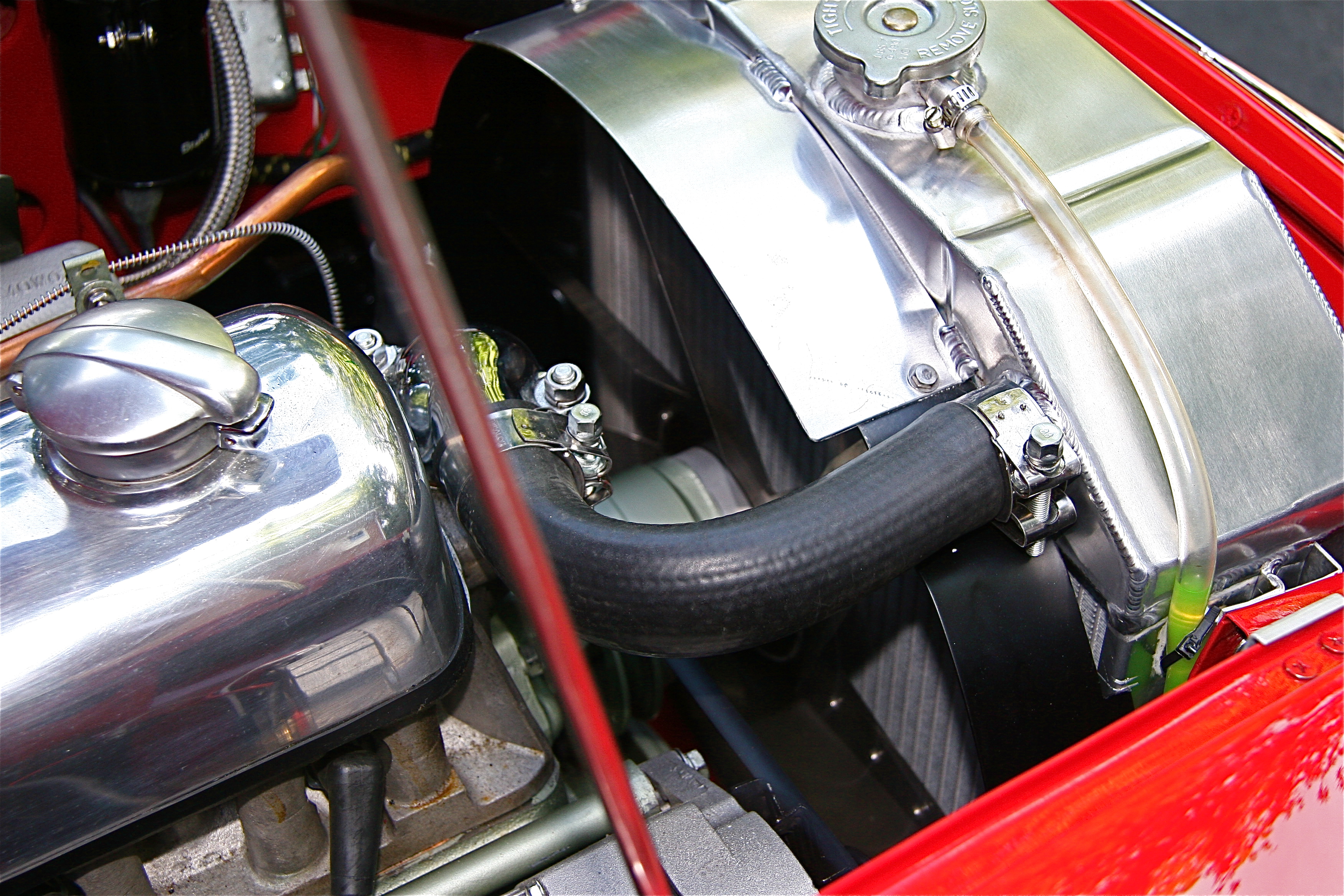
Radiator shroud
The Original Heater/Interior Cooling
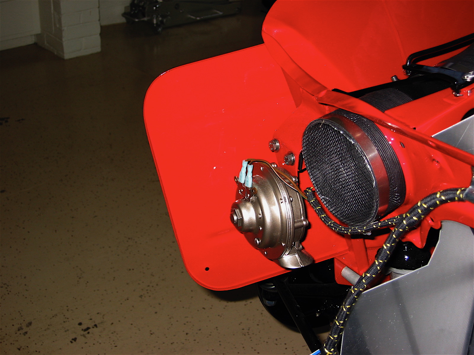
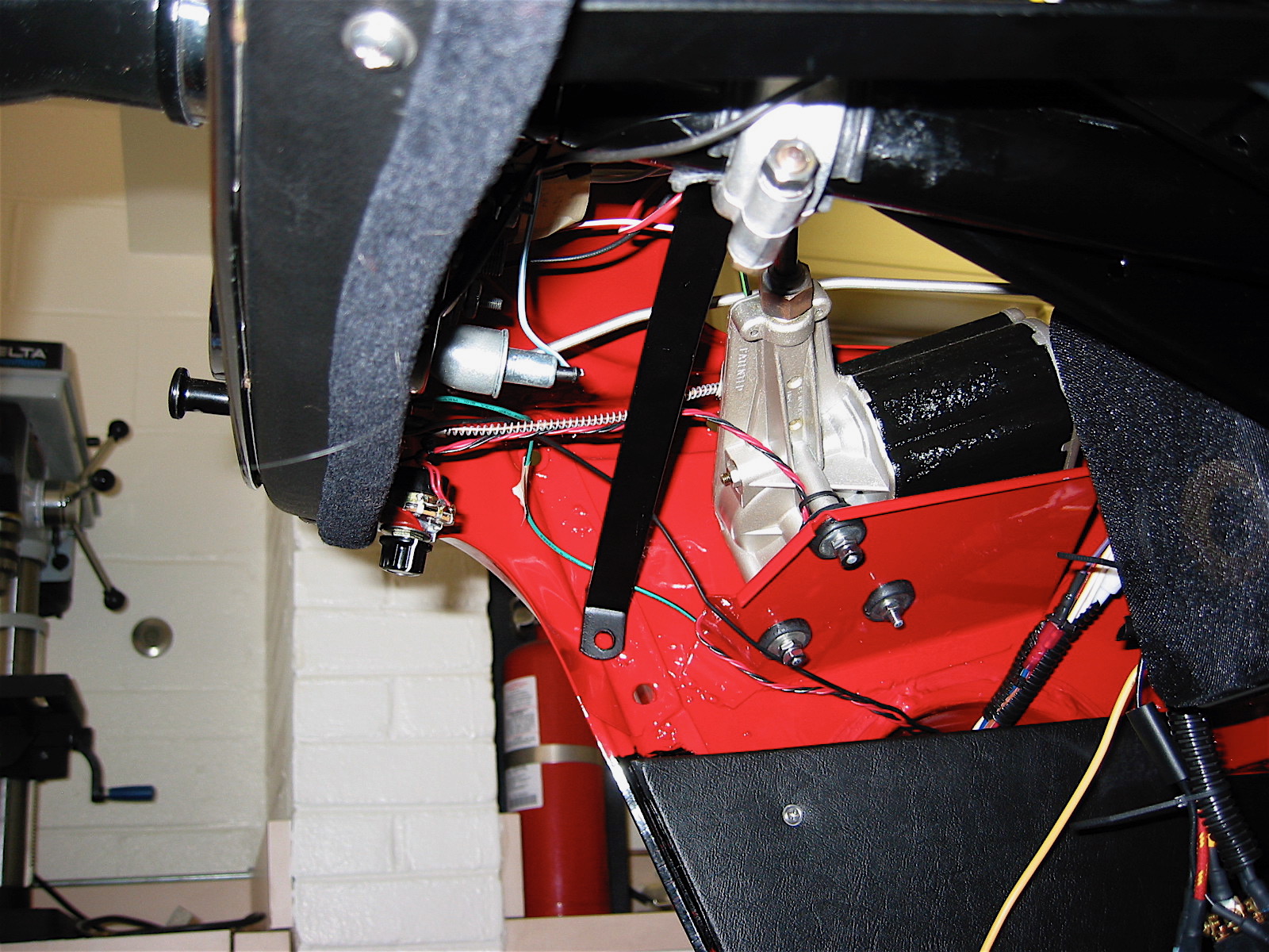
The original heater was a Smith’s hot water circulating unit, part # 8G9048. It was assisted by a fan blower secured to the right front wheel arch assembly. Fresh air was supplied to the driver’s side of the interior by a 4” paper/metal hose controlled by a fresh air assembly mounted at the front of the car.
Heater/Interior Cooling Modifications
Sealing all of the holes in the firewall is the first thing to be done if one is to keep the heat and fumes out of the interior. A helpful tip someone shared with me was to wait until dark and put a light in the engine bay. This way any holes or leaks can be easily spotted from the interior.
Dynamat Extreme and Aluminum Duct Insualtion
A number of products are on the market to help reflect heat and offer both heat and sound insulation. Dynamat Extreme is certainly on of the most popular. I applied Dynamat Extreme heat reflective and sound insulation material to my interior first. I then applied aluminum duct insulation on top of the Dynamat and under the carpet. All seams were sealed with aluminum tape. These two together have proven to be very effective in keeping the heat out!

Dynamat Extreme

Aluminum Duct Insulation
Modern Heater
For those (rare) occasions when I would choose to have more heat in the interior spaces, I chose to replace the Smith’s Heating unit with a contemporary unit supplied by Cape International. This unit has an internal two speed fan.

Cape International Heater
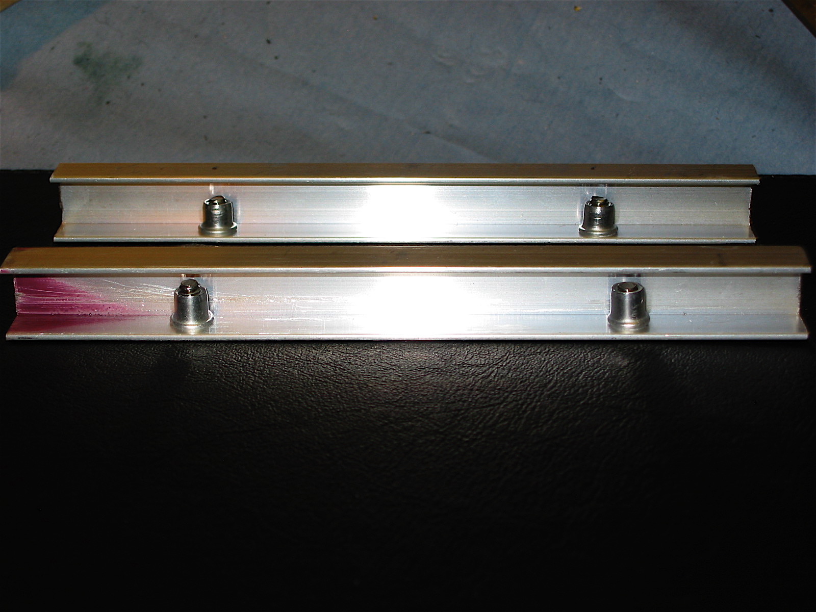
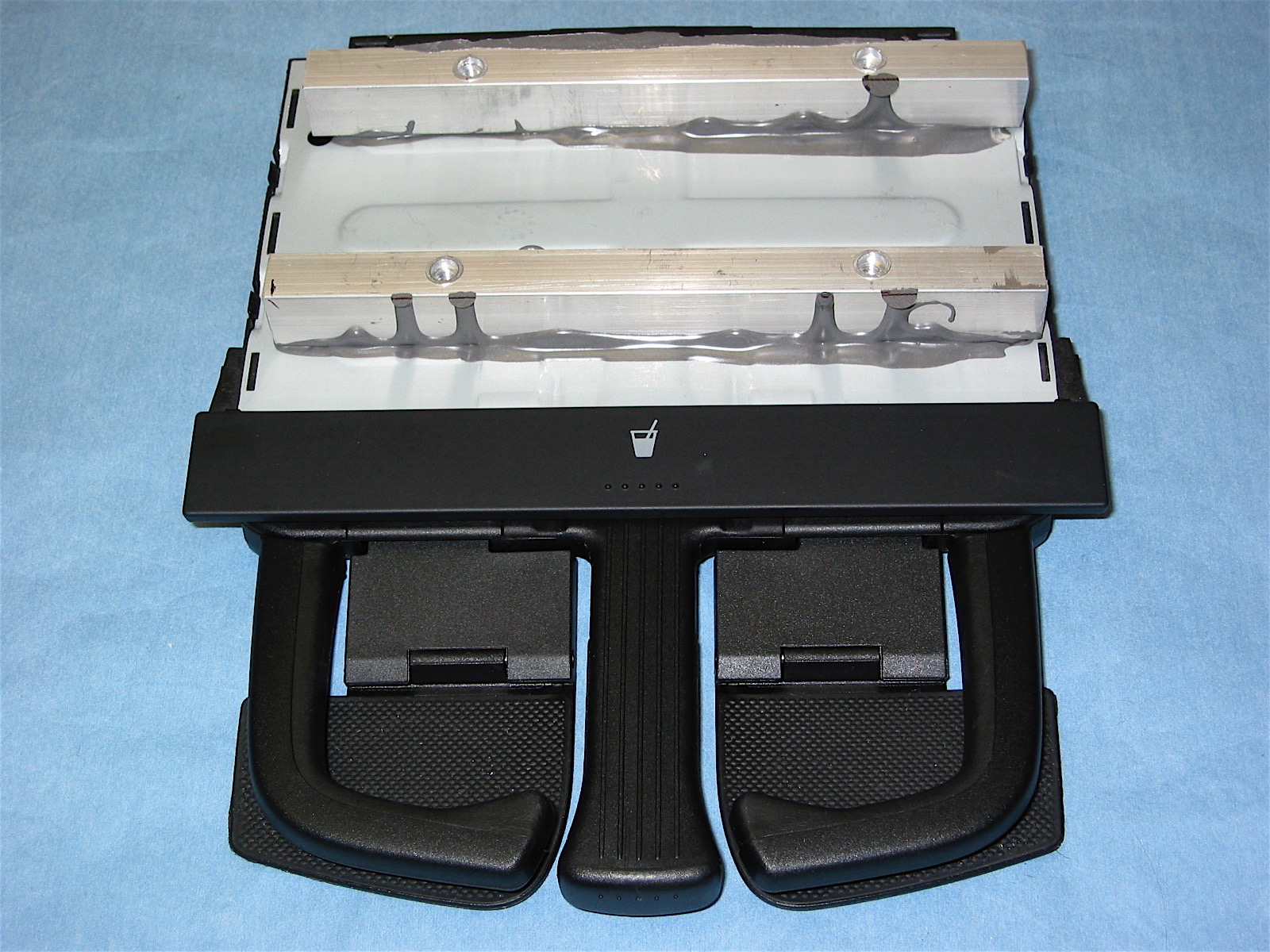
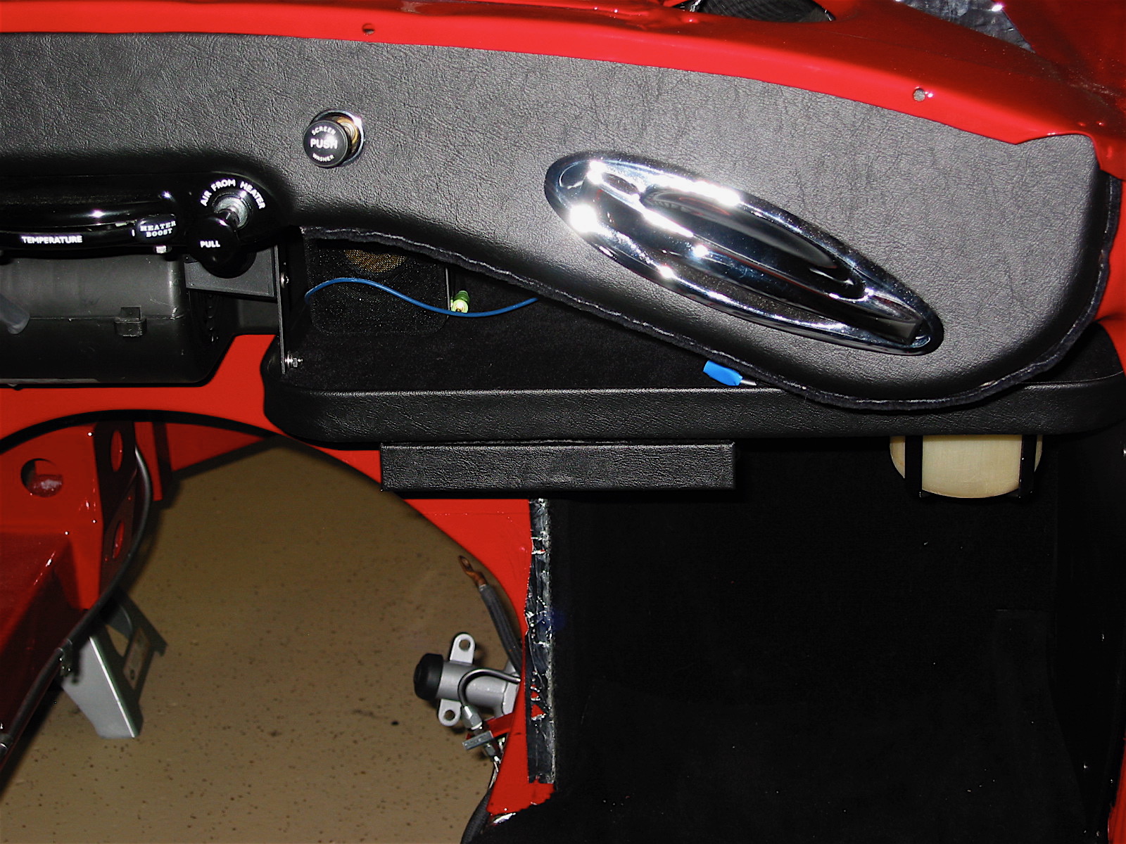
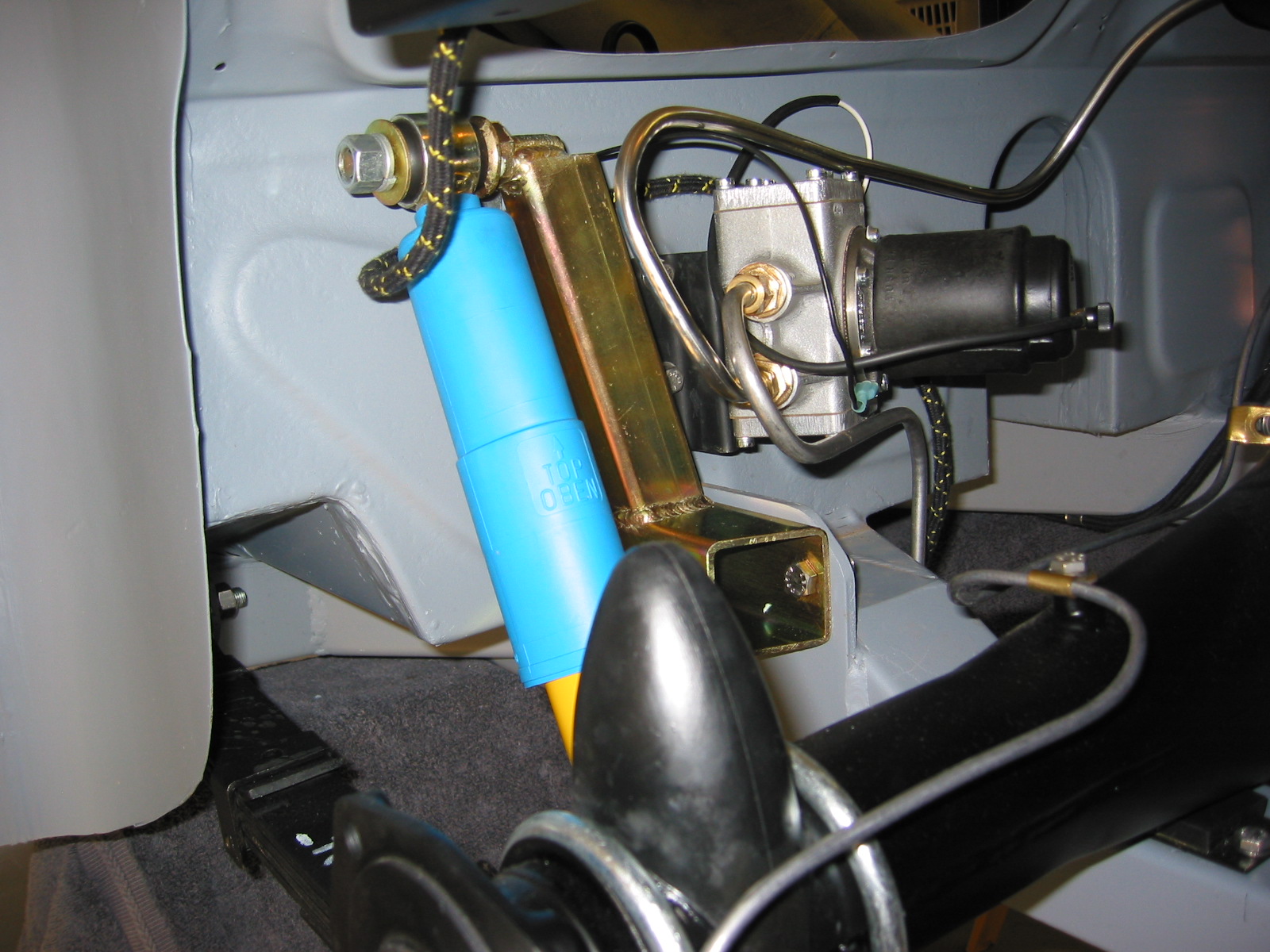
Fresh Air Supply
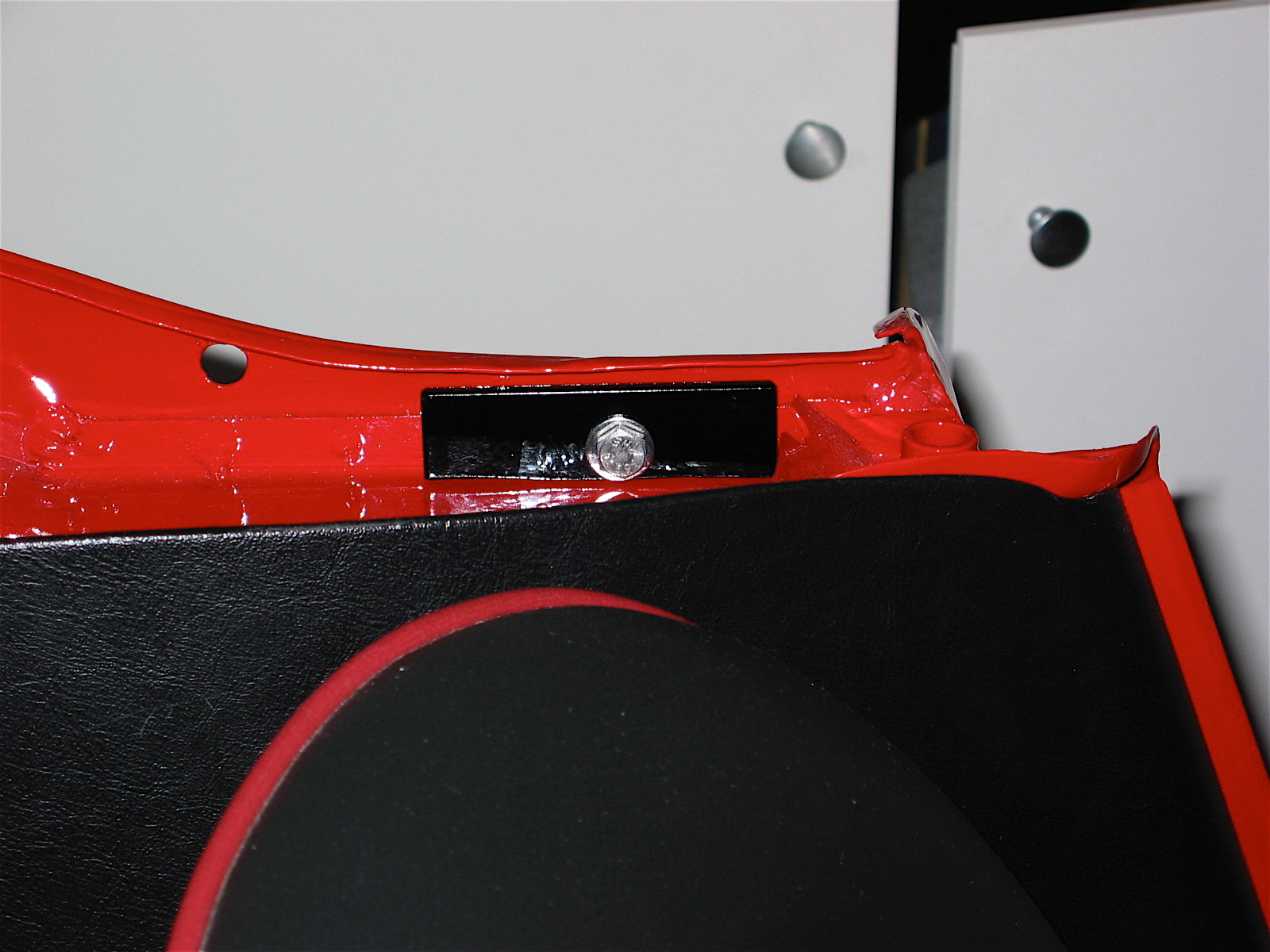
The original design of the car provided for some fresh air being delivered to the LH driver’s side of the car. Given that the Cape International Heater has its own fan, that left the original Smith’s blower to be used to blow fresh air into the passenger side of the car. I installed an air intake valve (upside down) just like the one on the LH side of the car, on the RH side, and then wired the blower to provide fresh air on the passenger side when desired. To be honest, I have found this to be useful for some ventilation when one has the hardtop in place, otherwise I am not sure that it was worth the effort! There are more details about this project in the restoration blog.

Ventilation Hose Assembly
zz