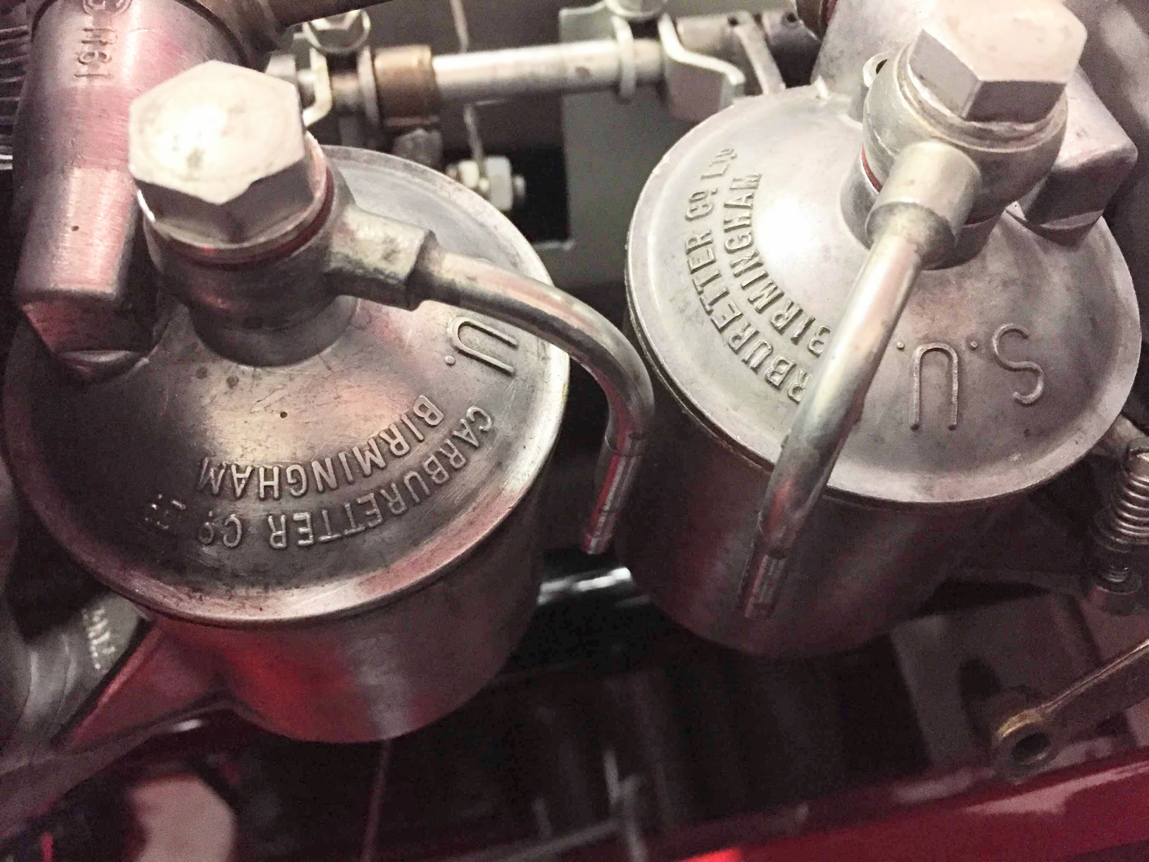
The Bugeye originally had 1 1/4″ twin SU carburetors. We upgraded to twin 1 1/2″ HS2 carbs shortly after purchasing the car. With the current restoration we are going to try a single 1 3/4″ HIF44 carb. We hope to attain equal performance without the need to balance twin carbs. The single HIF carb was routinely used on Minis with essentially the same engine. The HIF 44 is SU’s most modern carb of the period. The float bowl is integrated into the bottom of the carb body rather than a separate float bowl as with the HS2s.
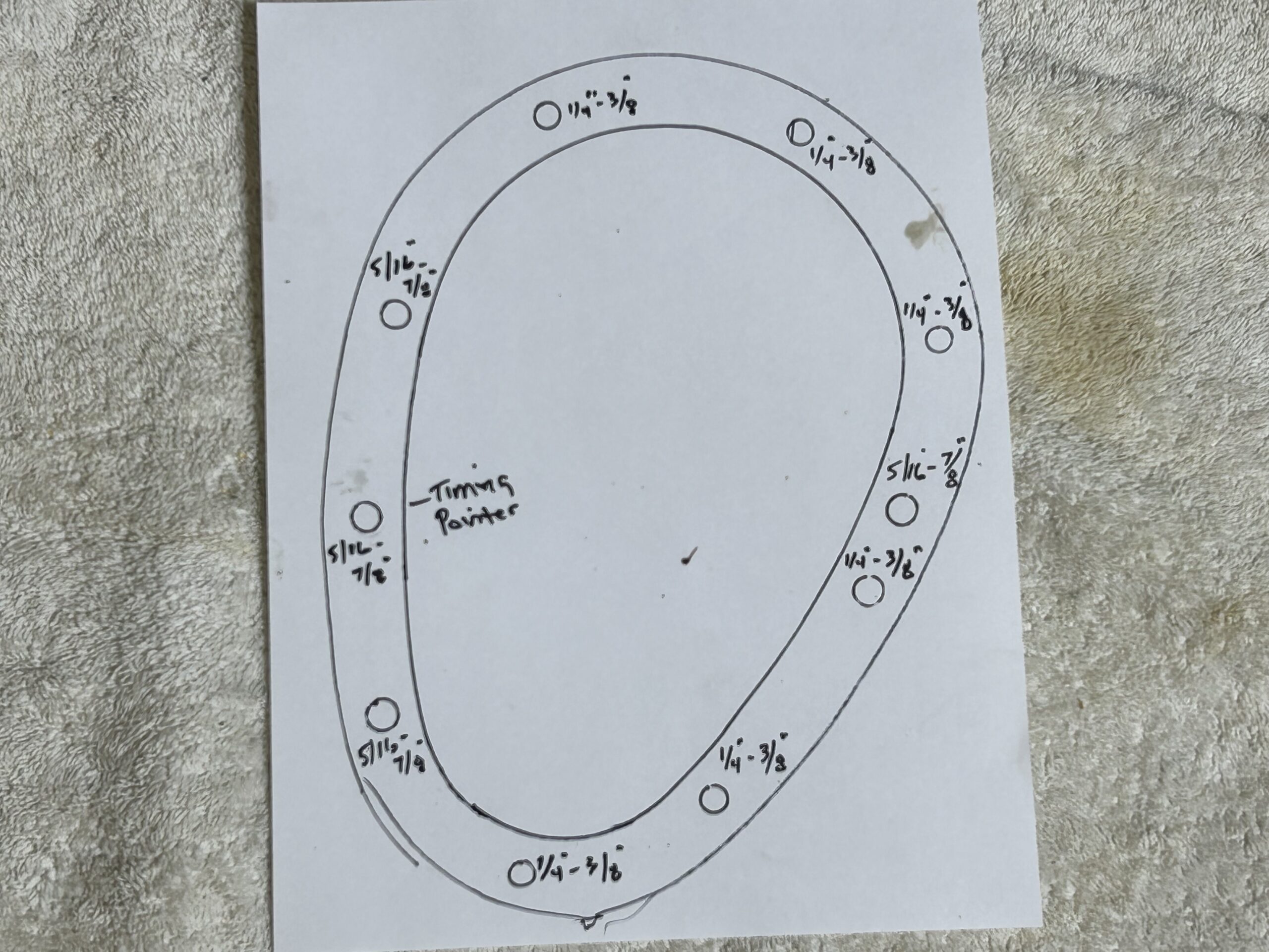
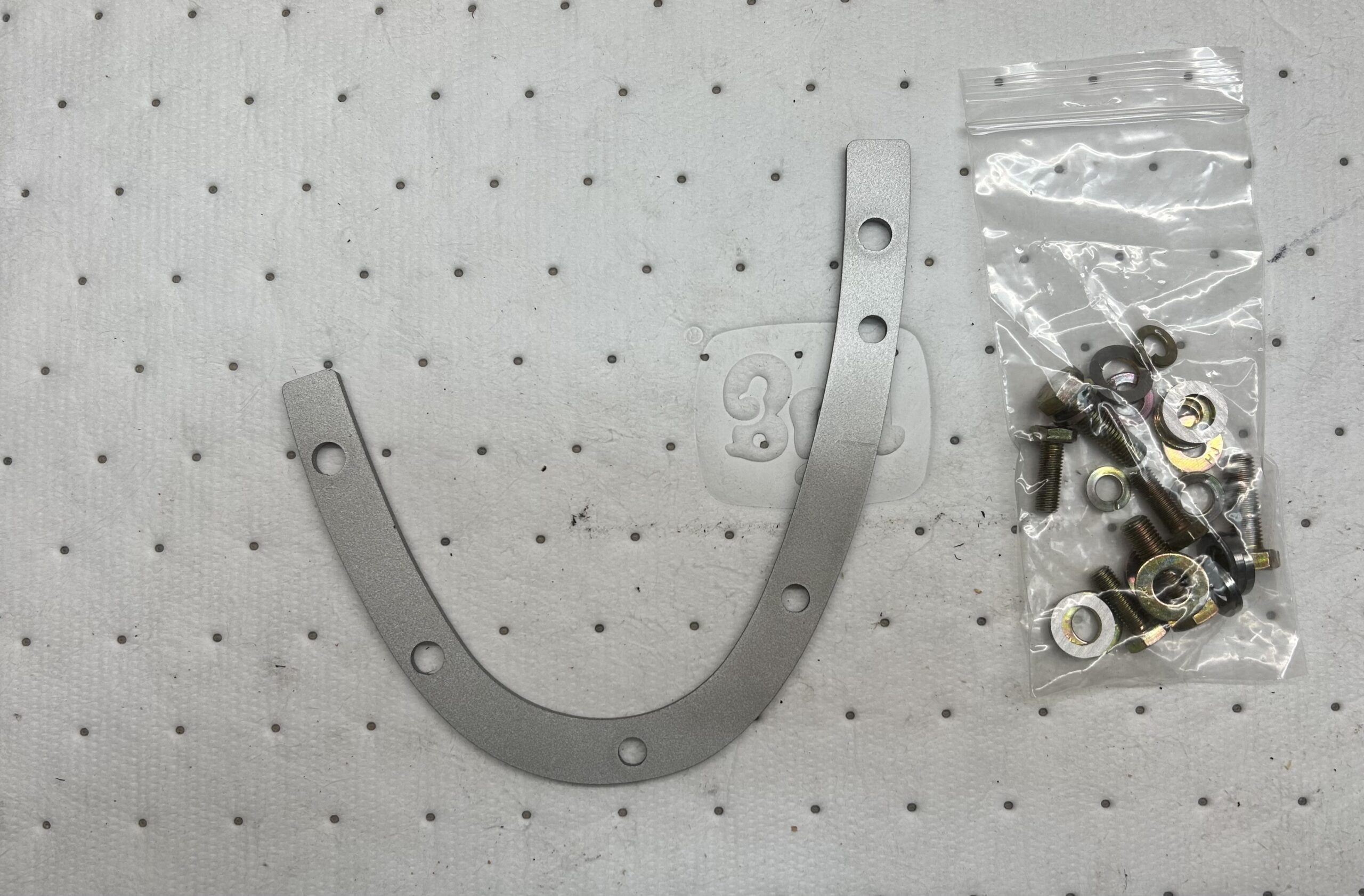
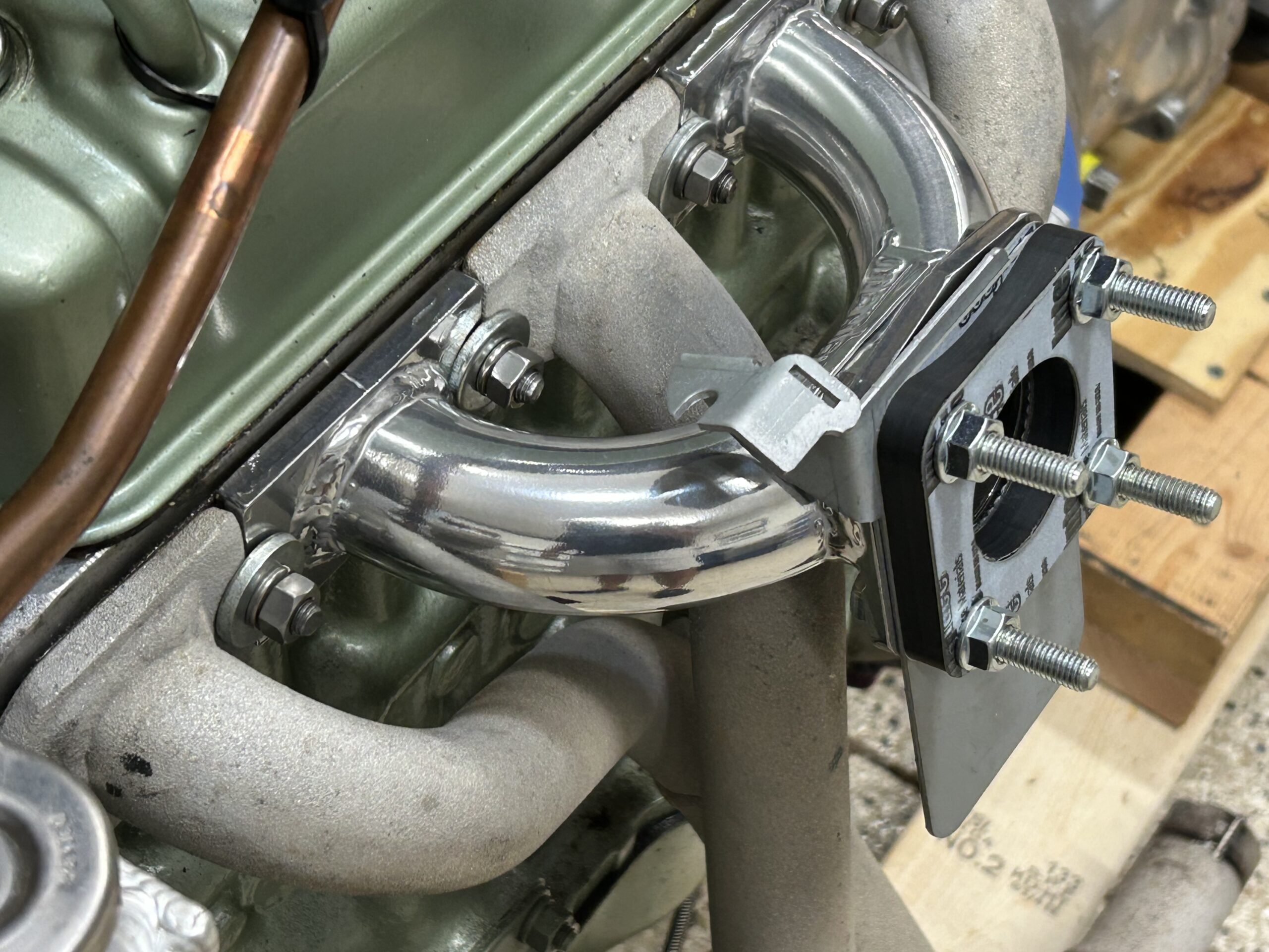
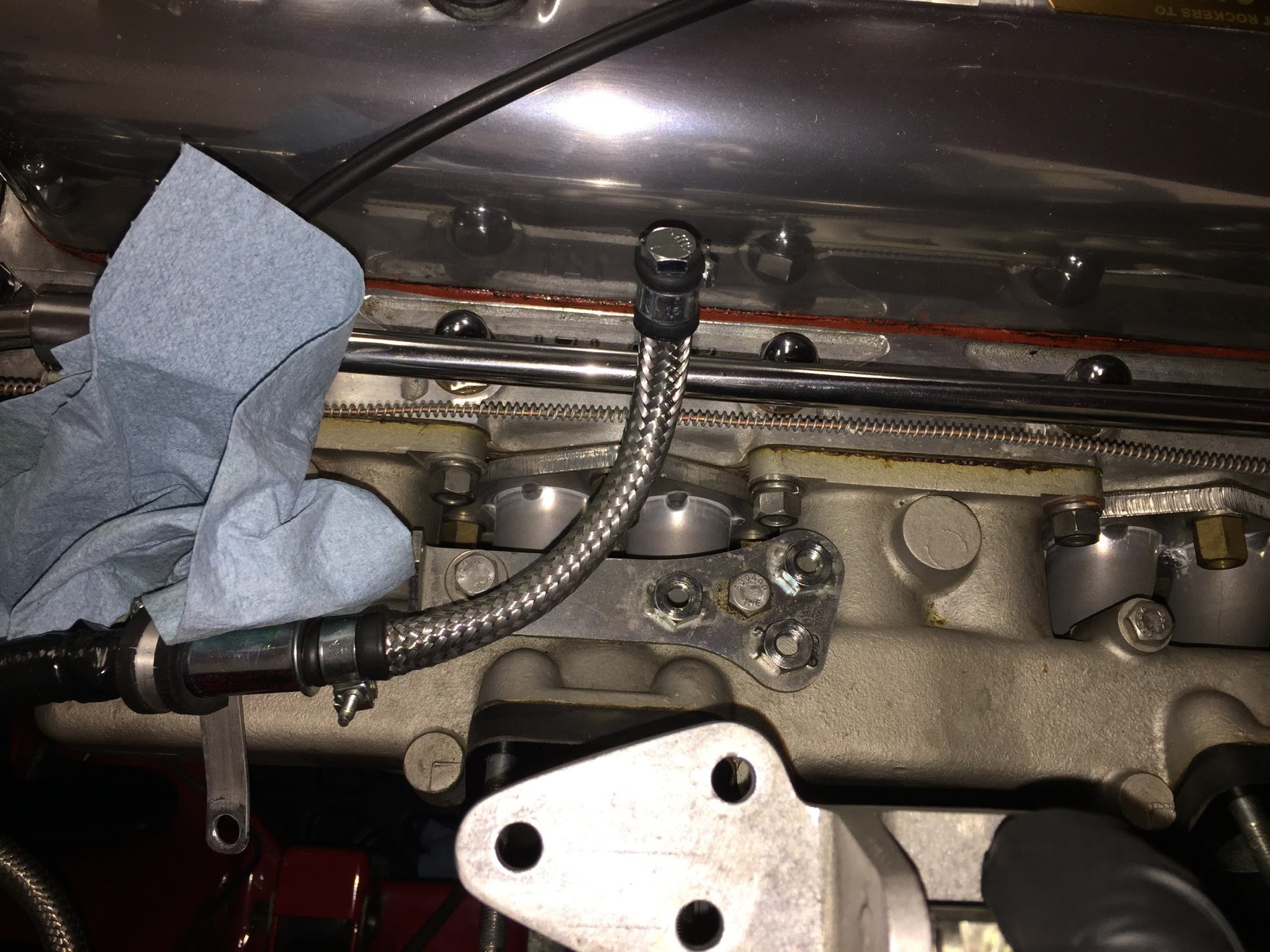
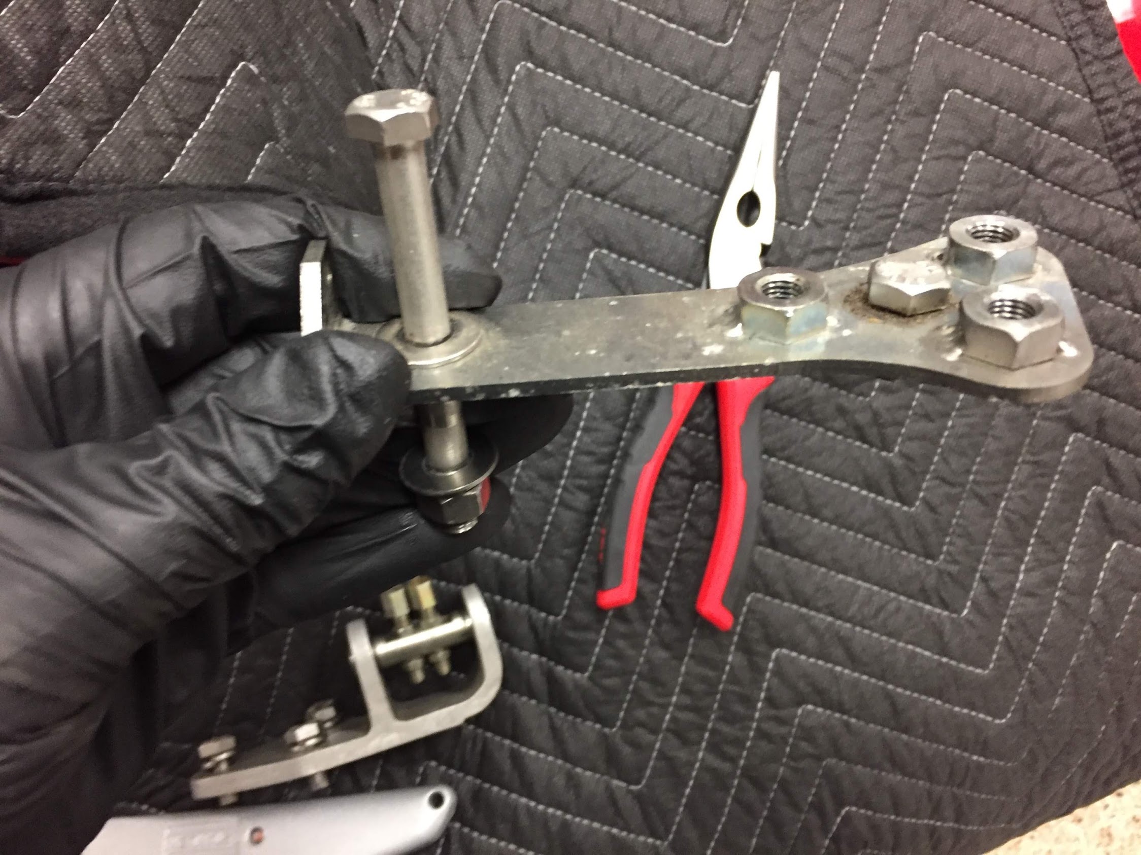
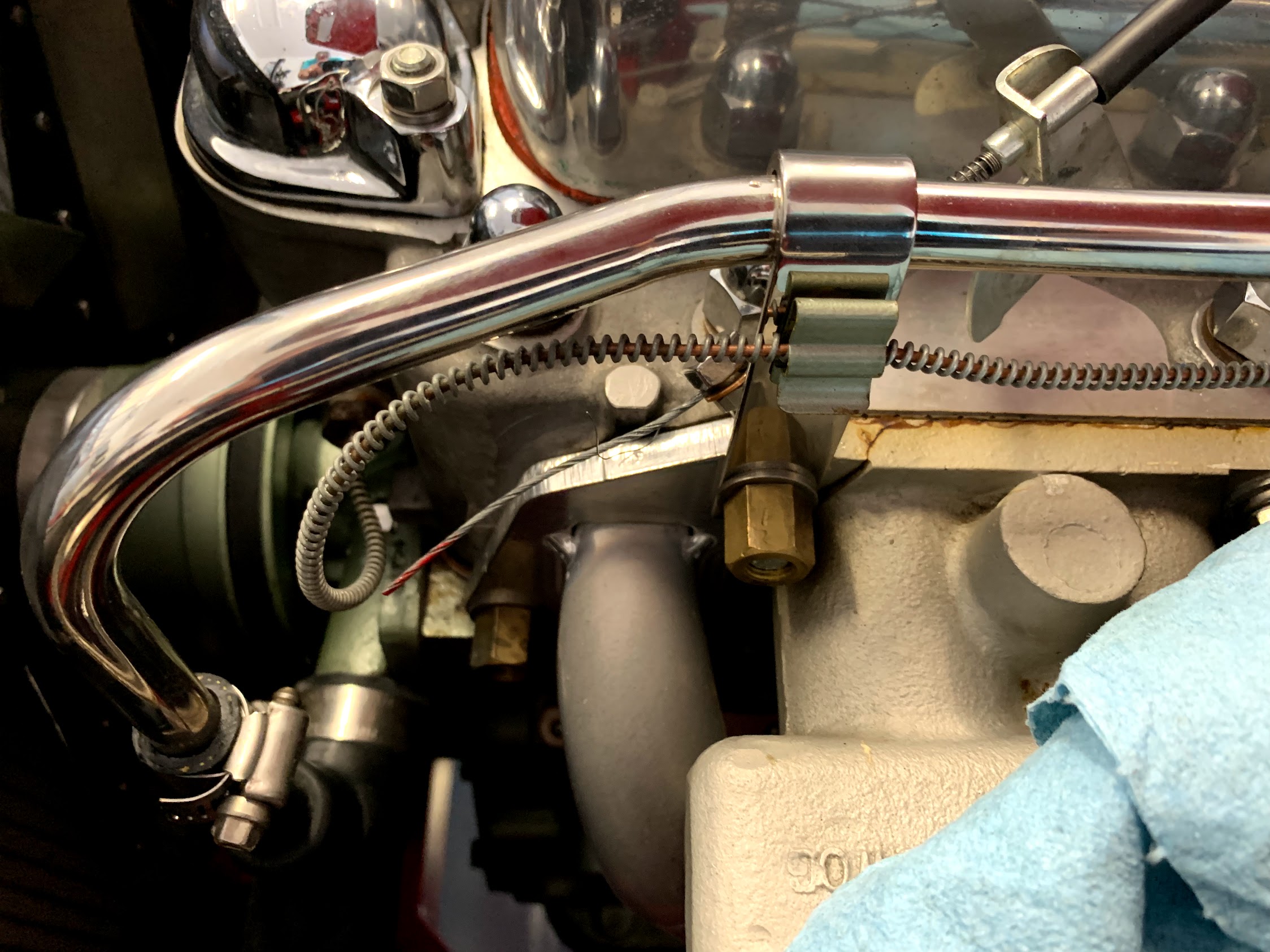
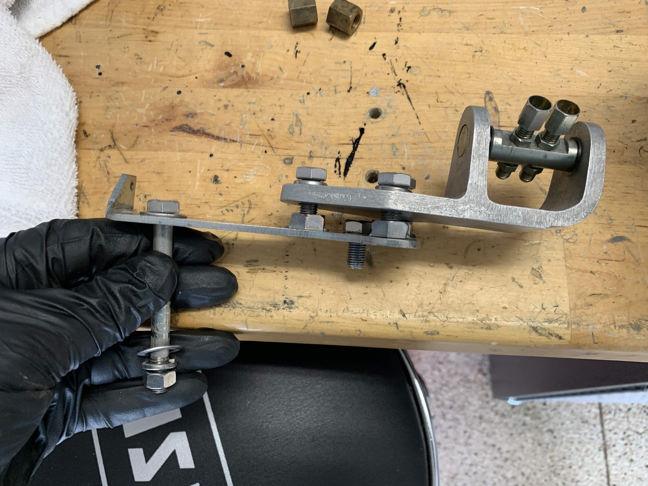
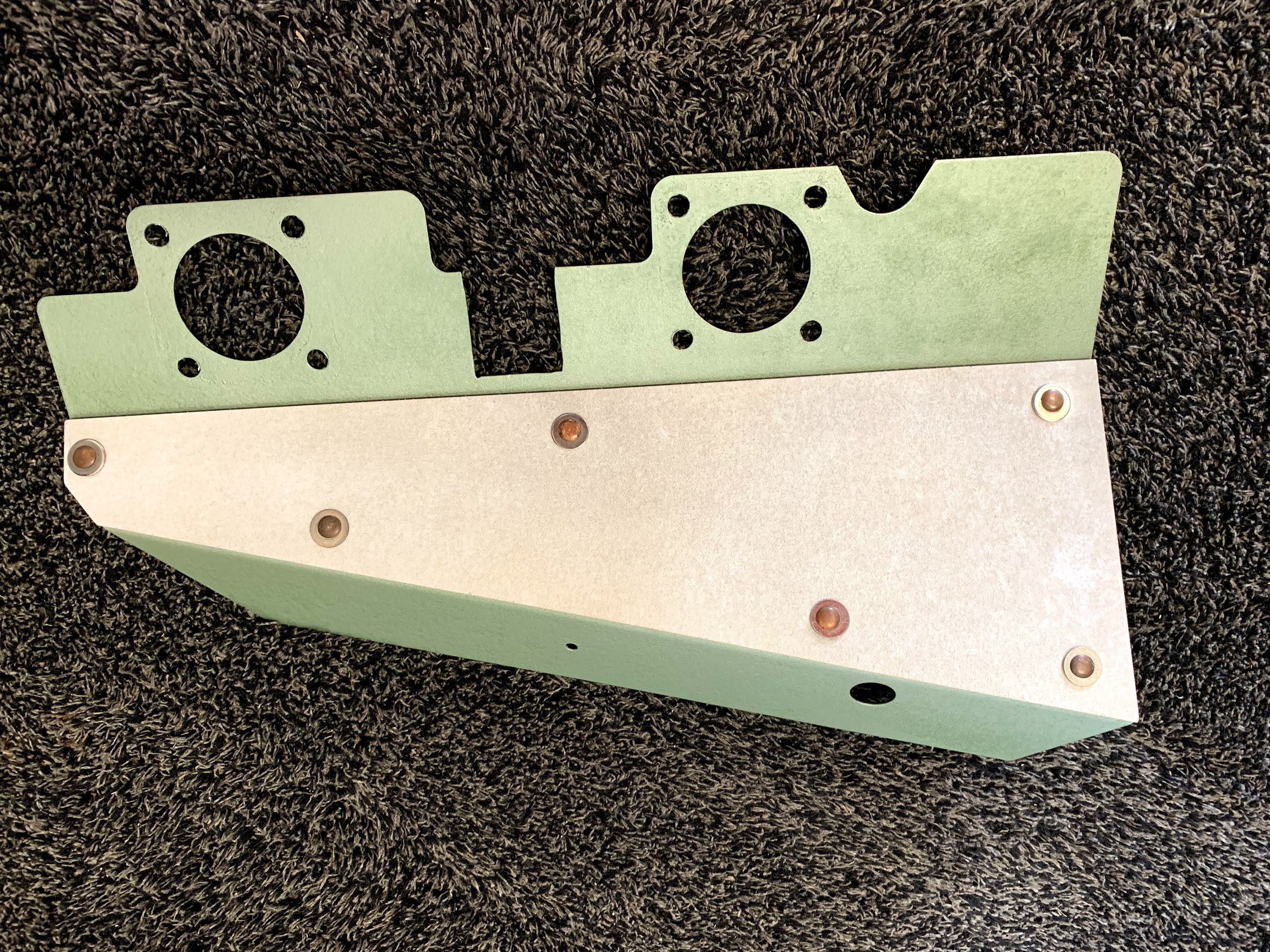
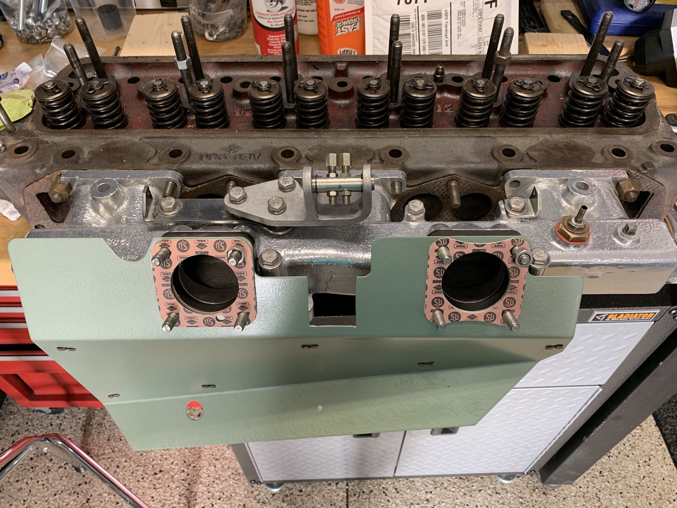
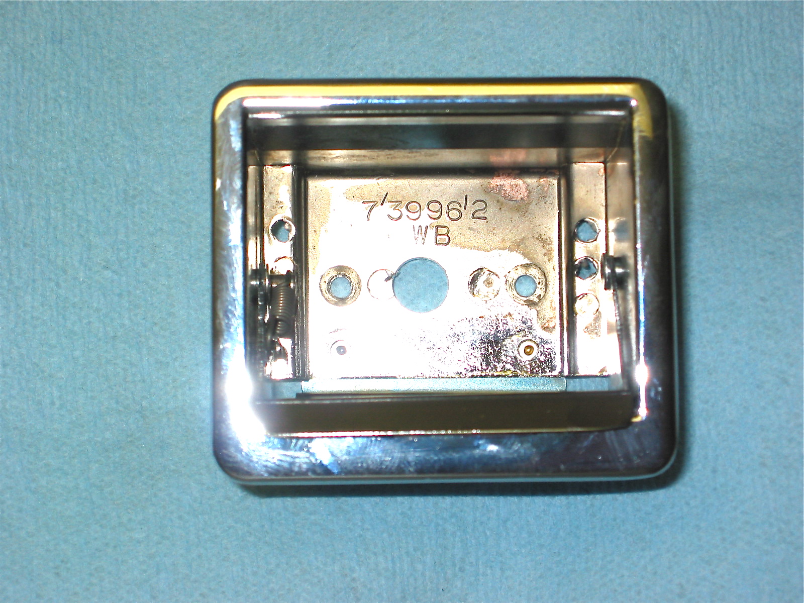
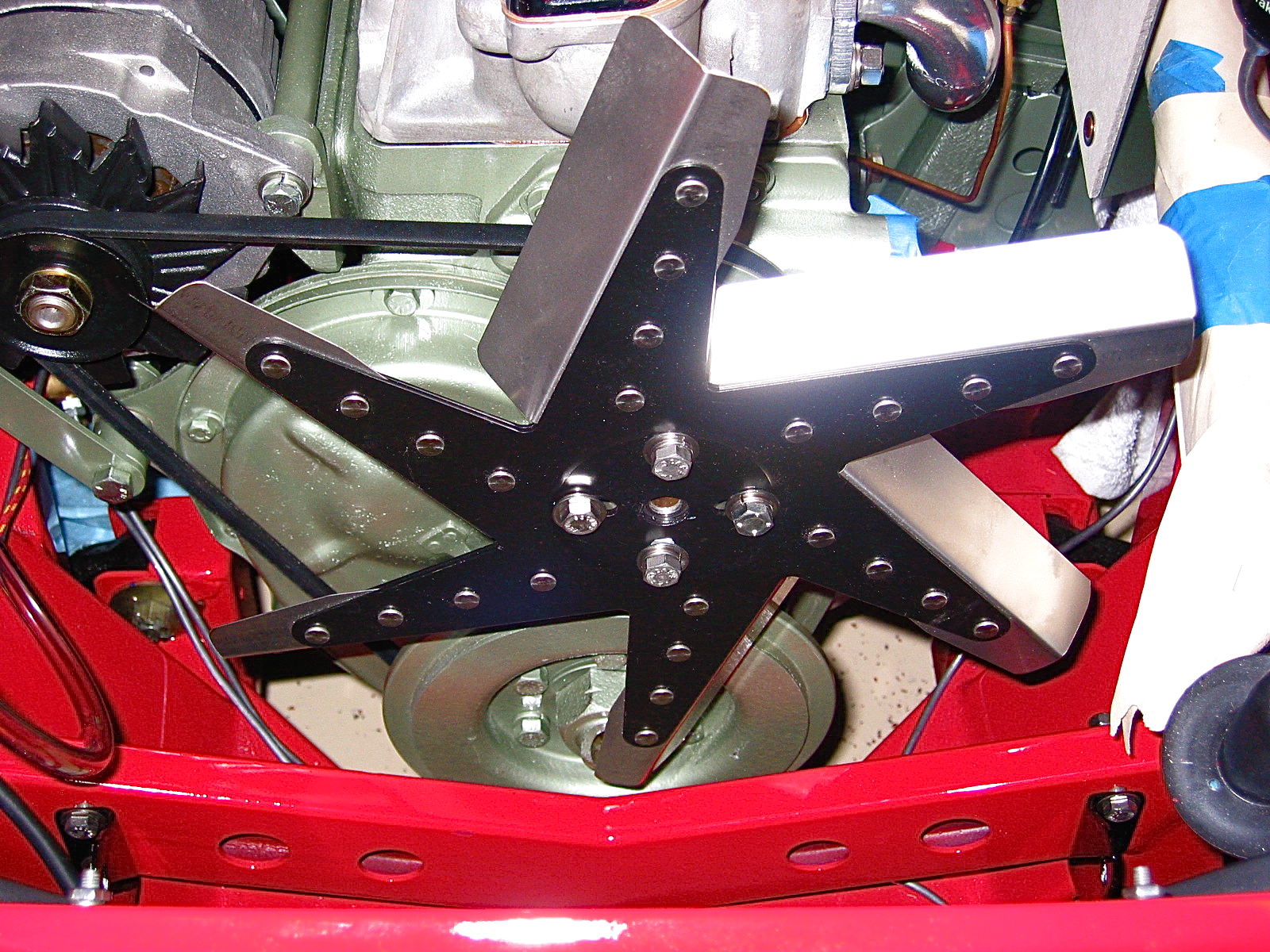
Using the HIF carb requires the use of an appropriate heat shield with integrated securing points for the throttle and choke cables. I ordered this one https://www.ebay.com/itm/163969687994 not only is it polished stainless, it also provides an angled extension under the bottom of the carb (where the float bowl is located) to provide a little extra heat protection. This is a very nice piece.
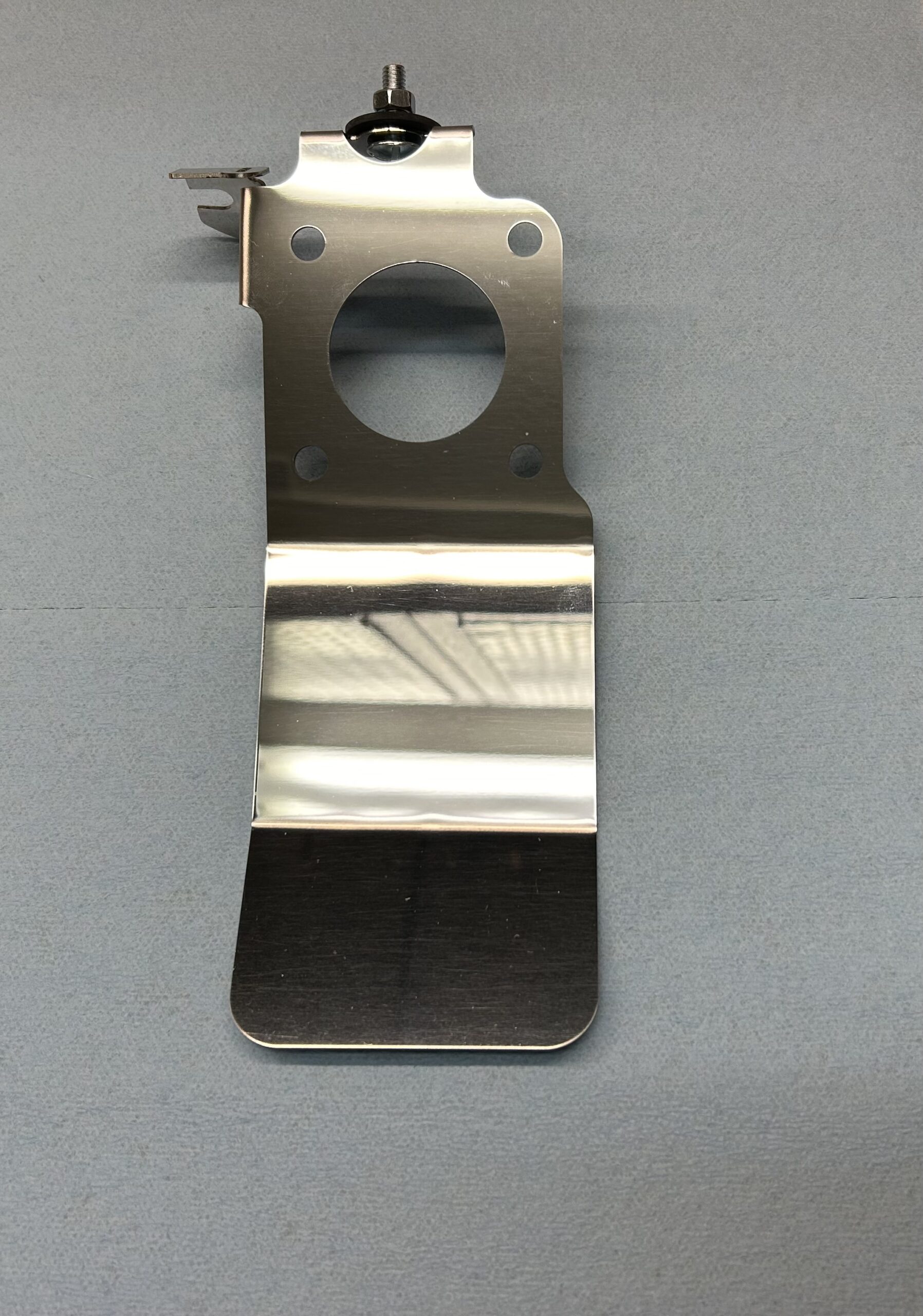
Modified stainless HIF 44 Heat Shield
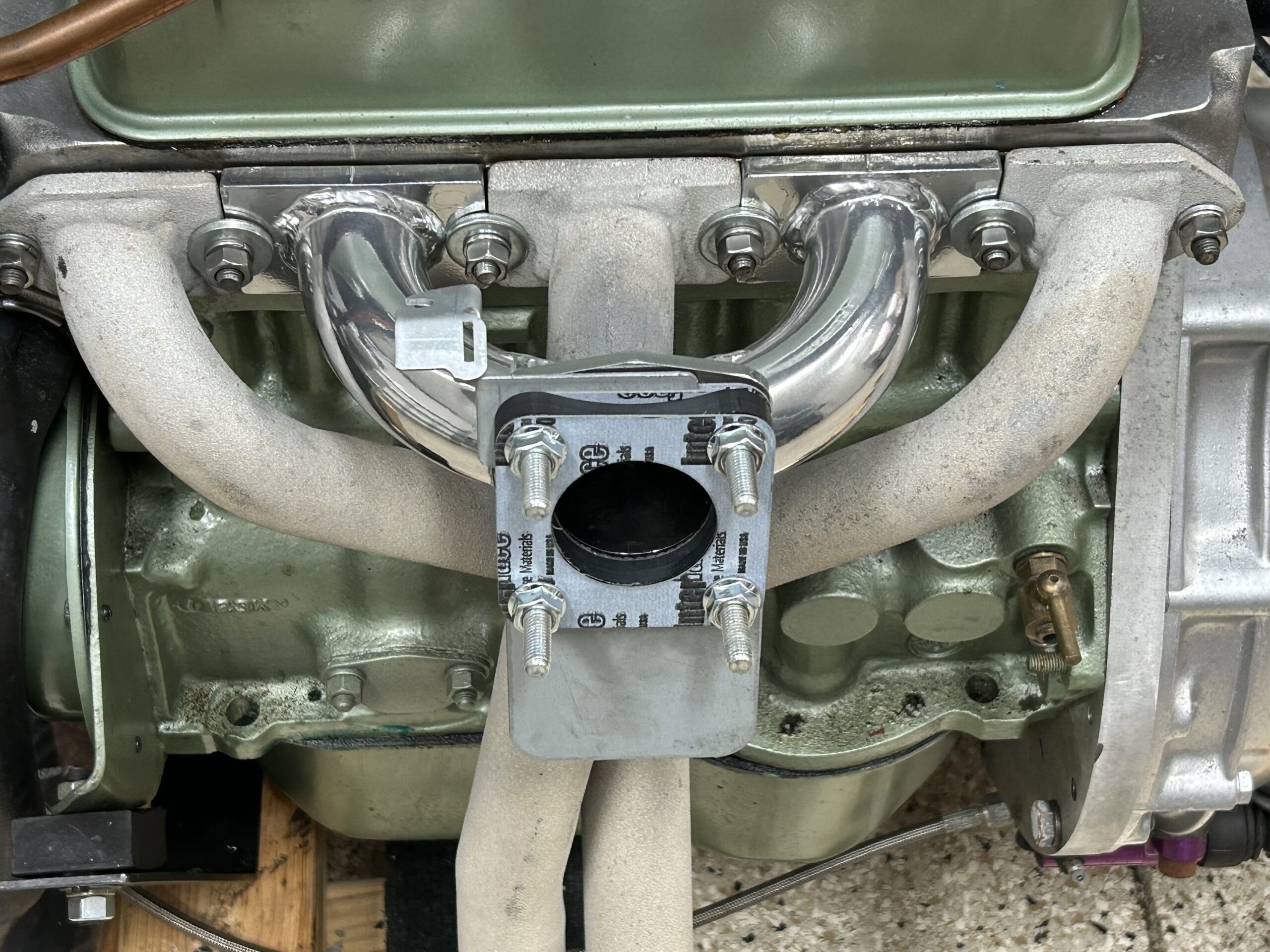
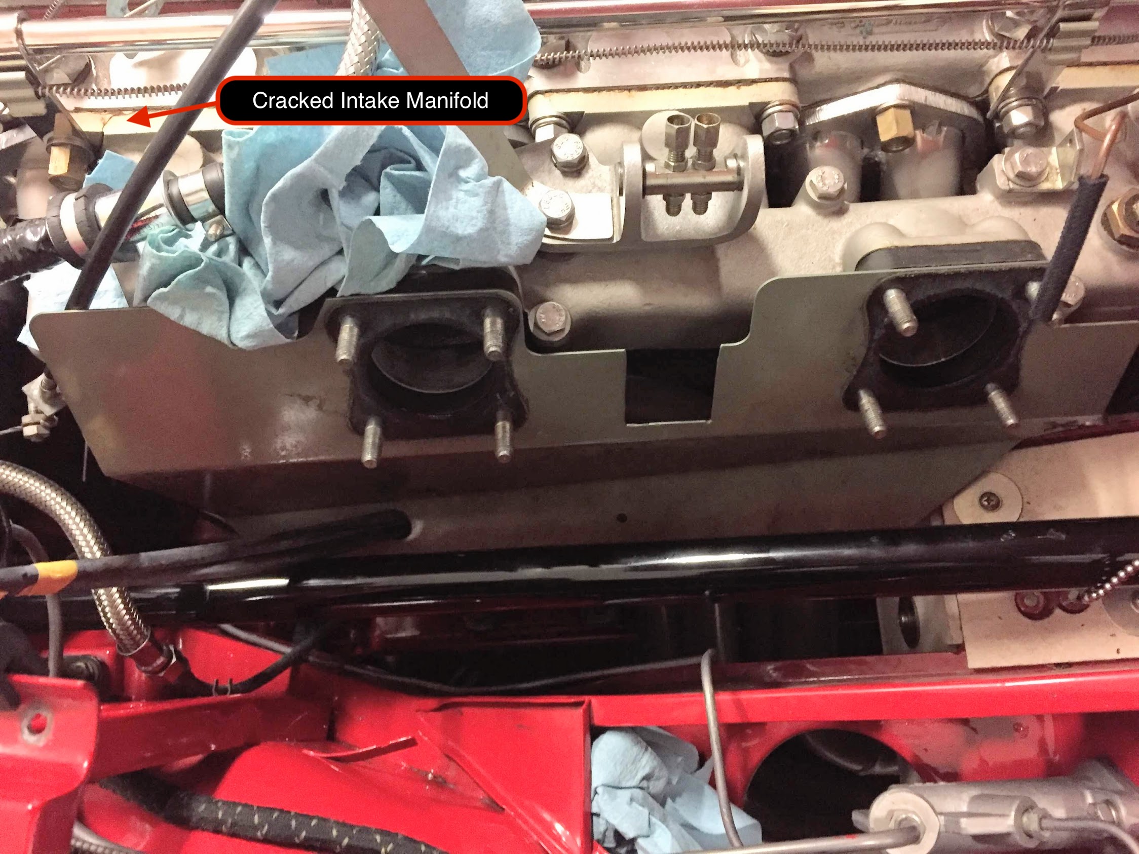
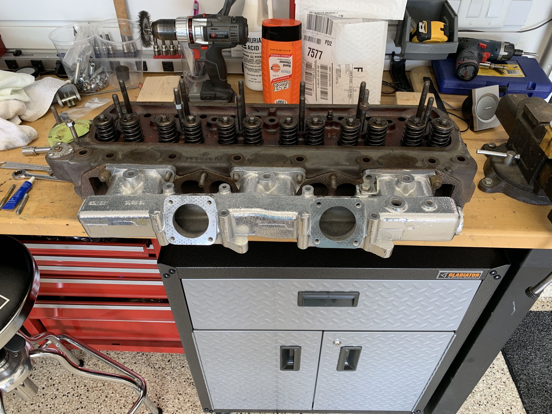
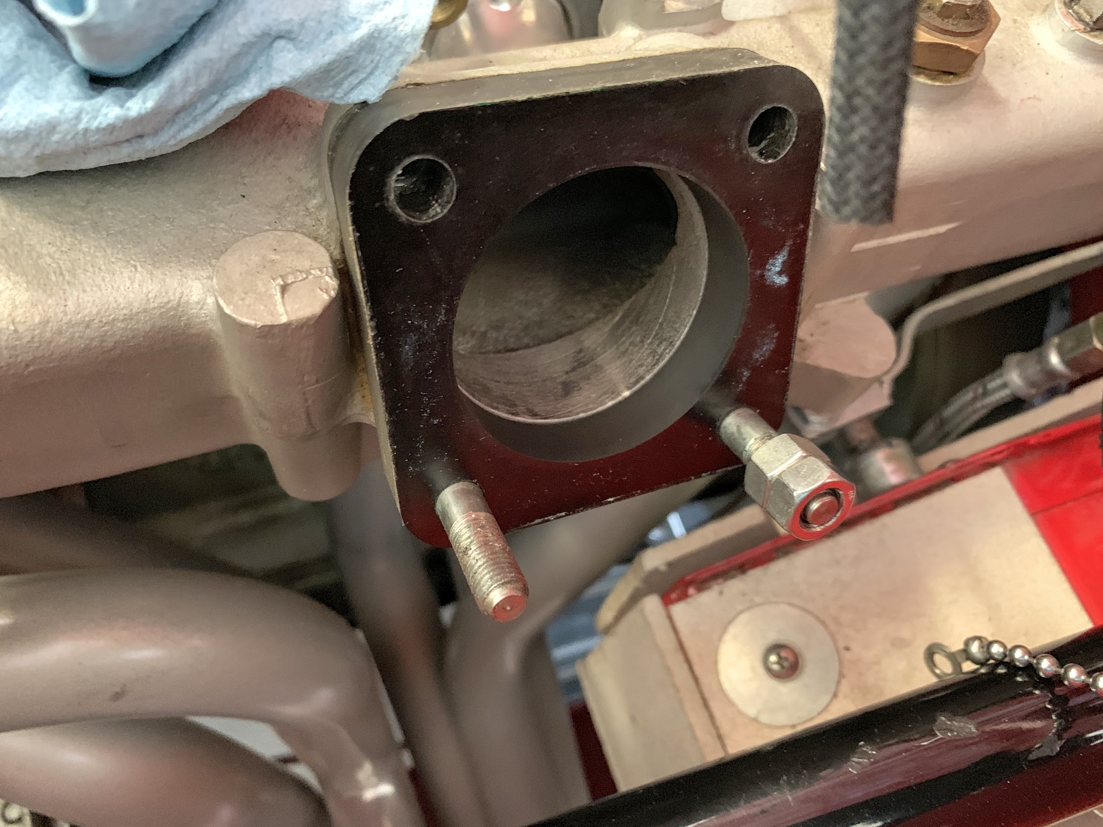
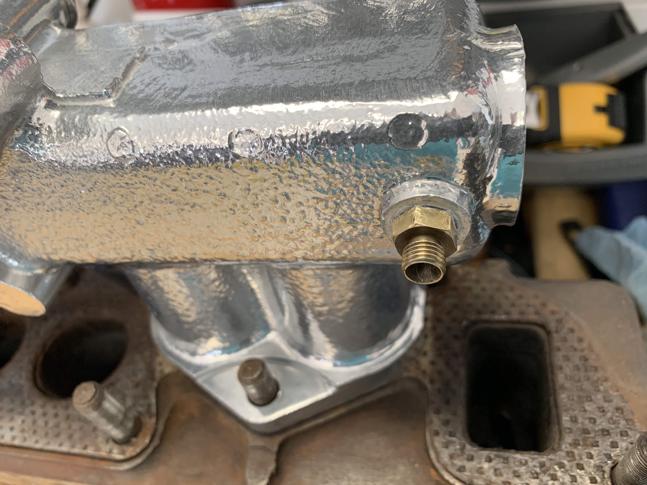
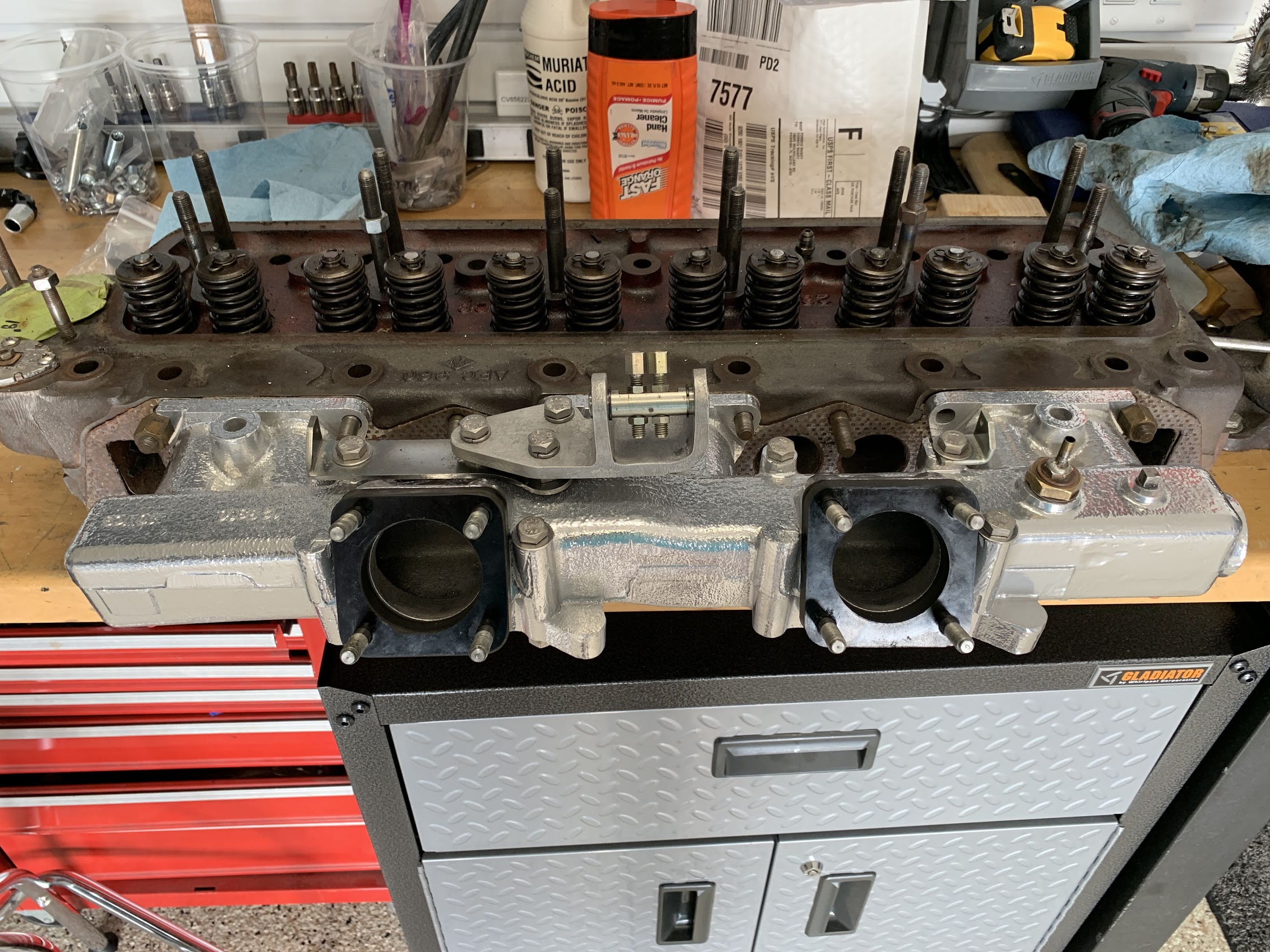
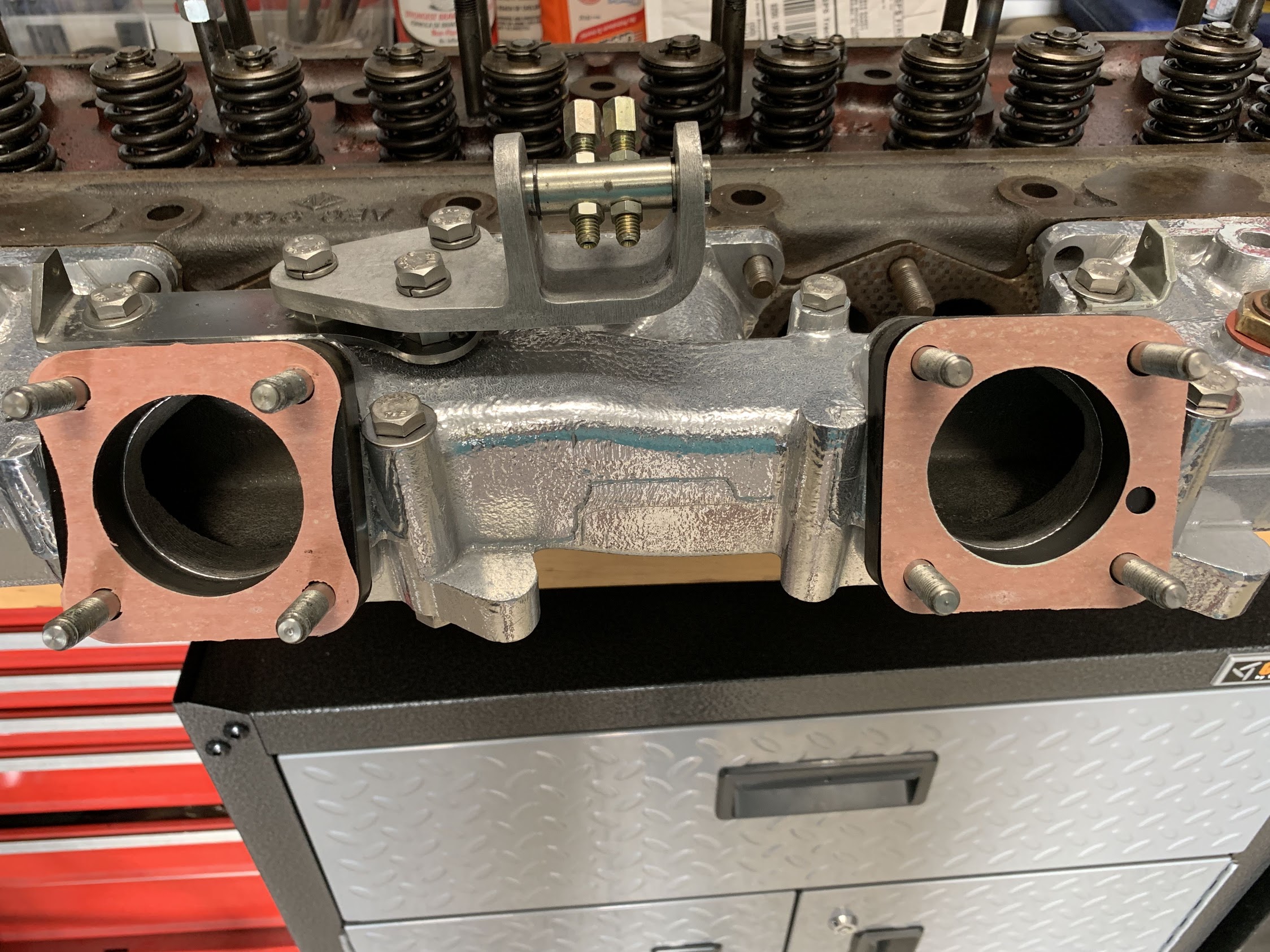
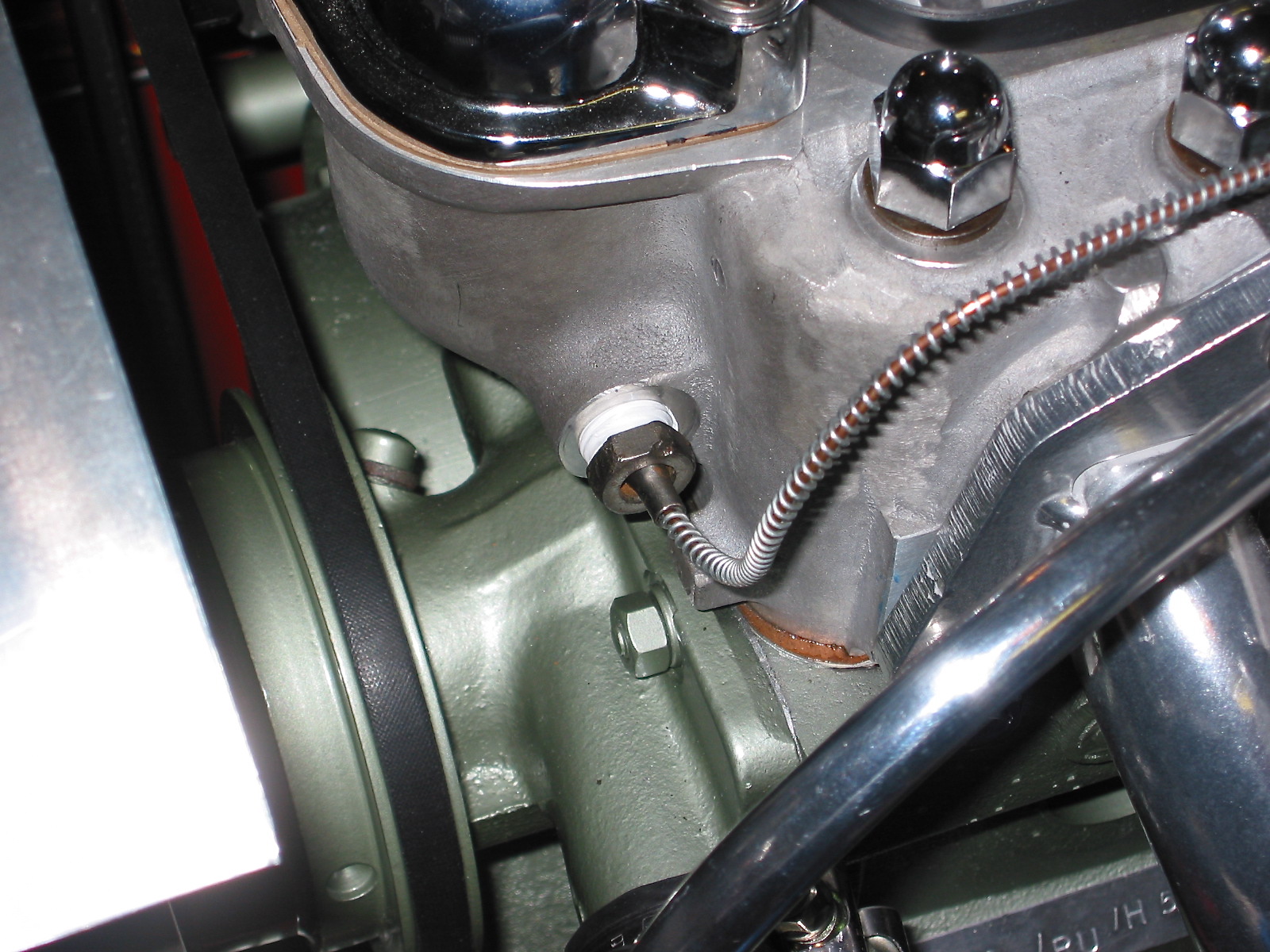
A custom intake manifold is also required on the Bugeye. Sourced from Maniflow in the UK. This manifold lowers the carb so that it will not foul against the bonnet.
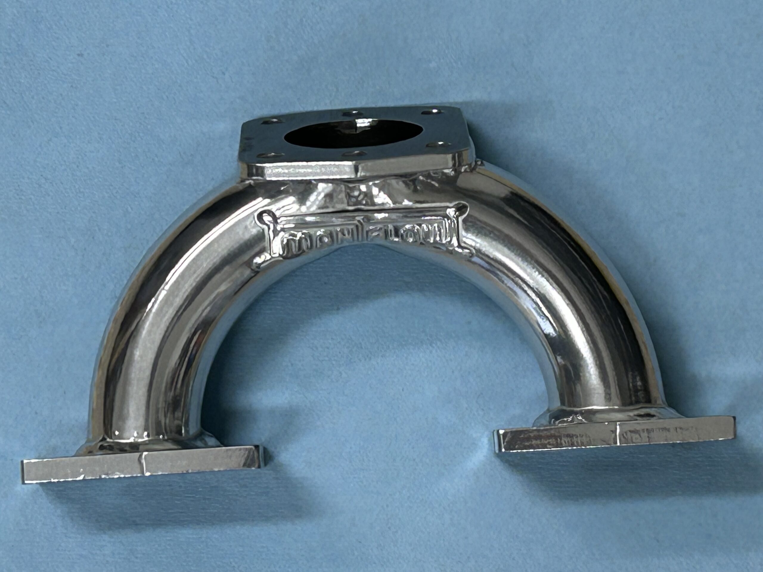
Maniflow 1 3/4″ Intake Manifold Jet-Hot Coated
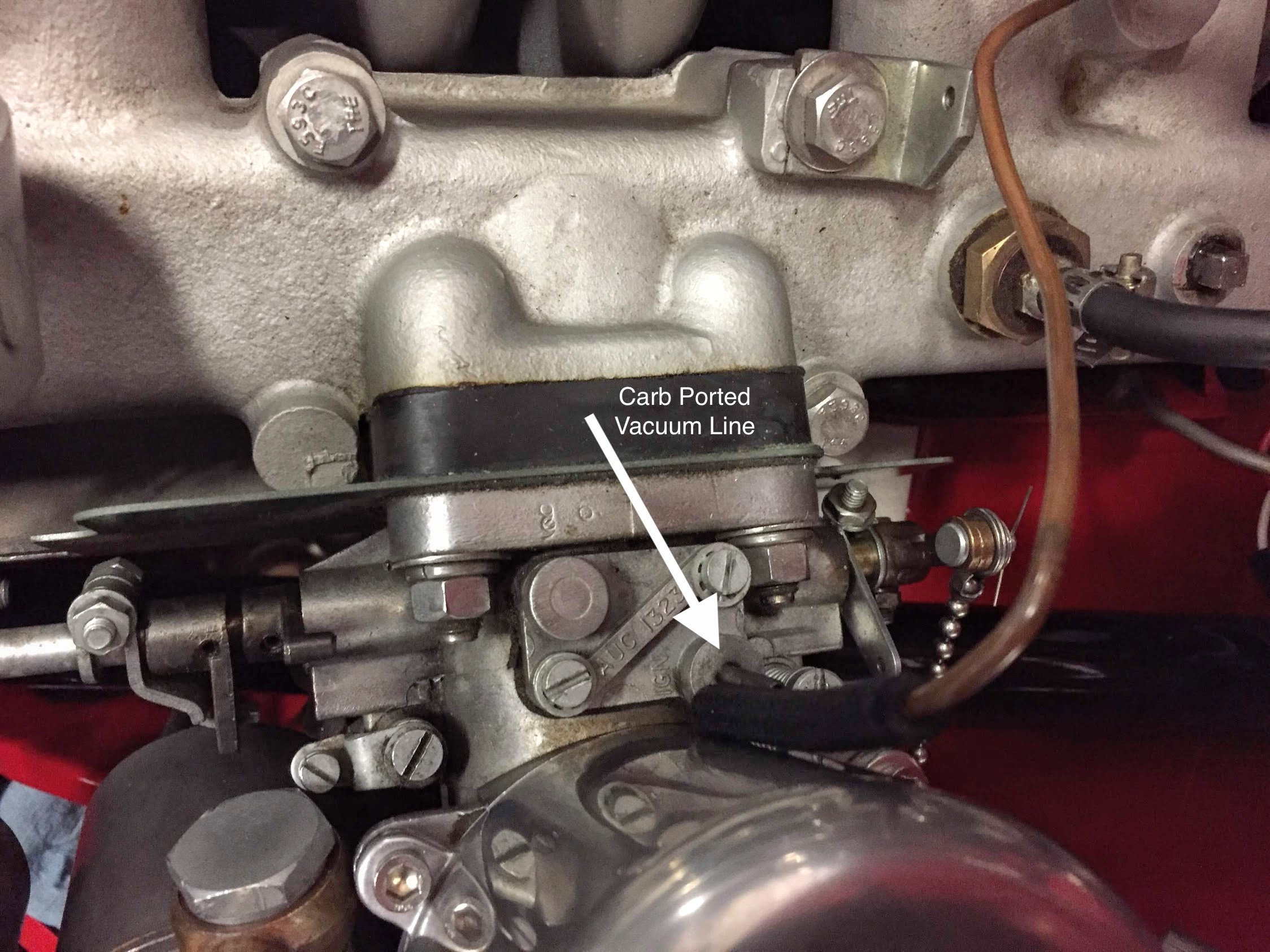
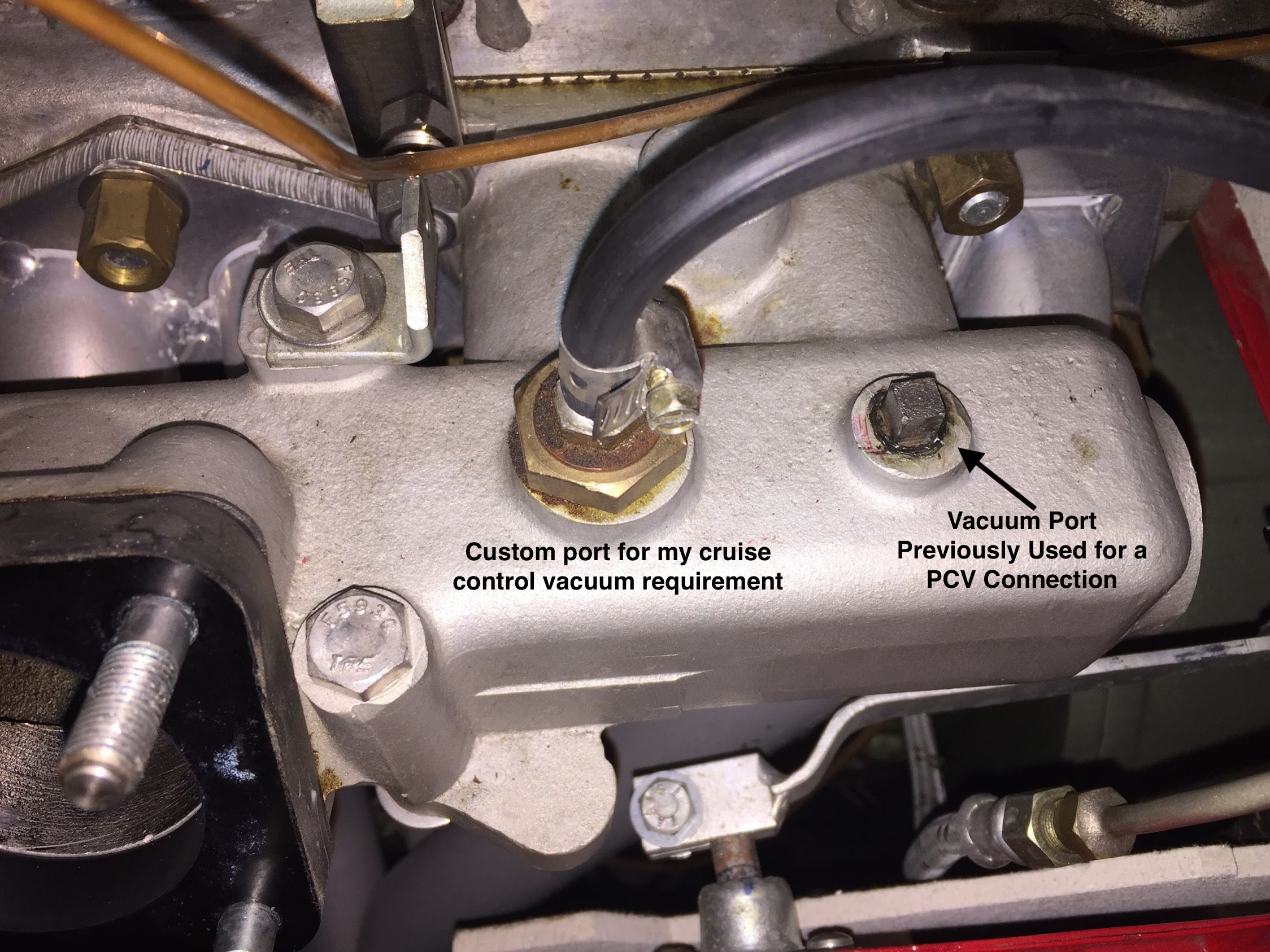
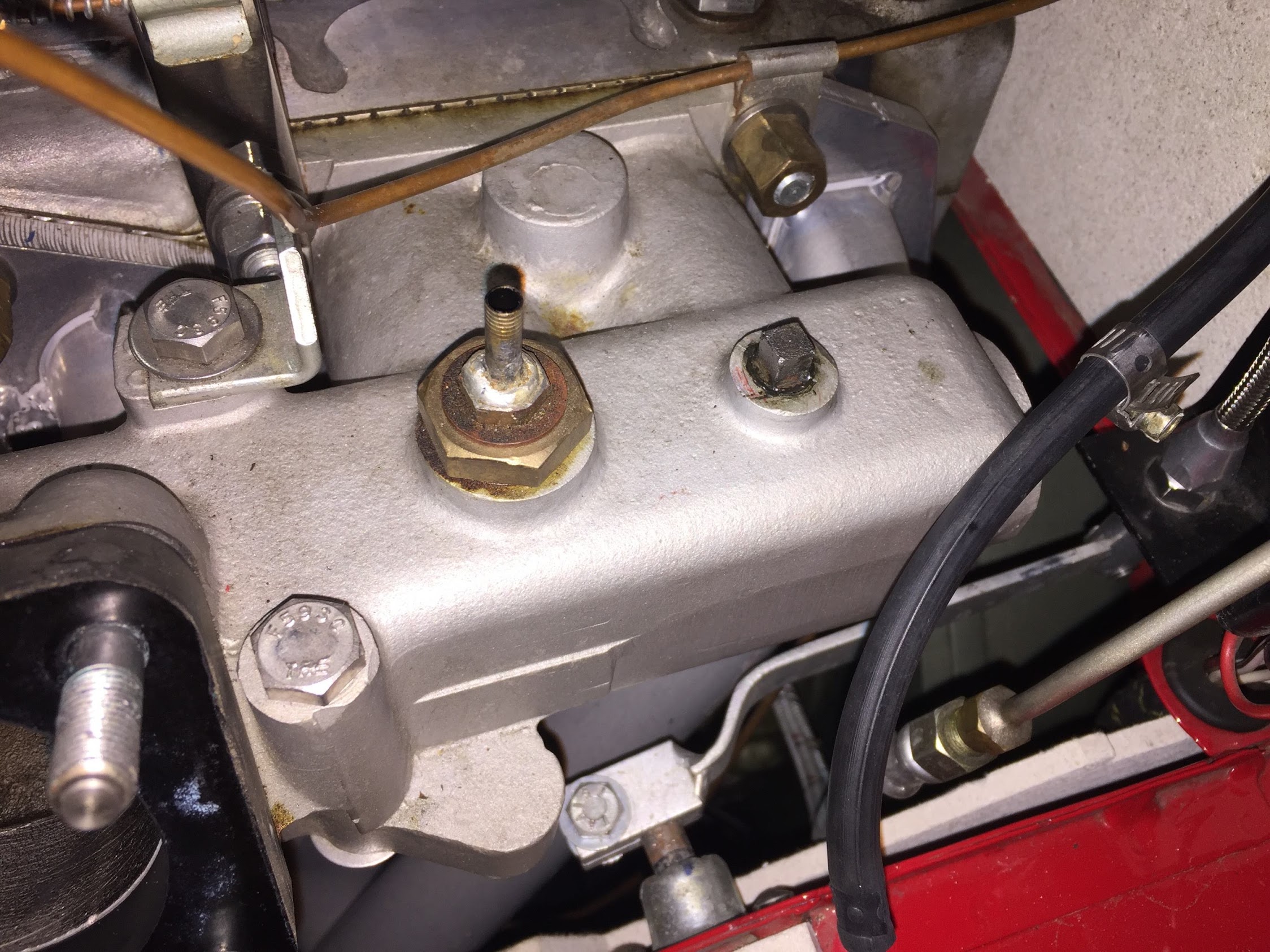
After purchasing the HIF44 we sent it to A.C. Dodd in the UK to have him modify it slightly. The biggest change was converting the unit from manifold vacuum to ported vacuum. Bugeye Restoration Video Episode Fifty-nine reviews the features of the HIF 44 and explains the modifications made to it by A.C. Dodd to prepare it for use in the Bugeye.
https://vimeo.com/924772088/d53a91b278?share=copy
Episode Fifty-nine includes the following content:
0:05 – HIF 44 carb documentation
0:45 – Applications of the HIF 44 carb in other cars
1:37 – HIF 44 carb needle
2:20 – Manifold and Ported vacuum
2:26 – HIF 44 Carb heat shield
2:32 – Maniflow intake manifold
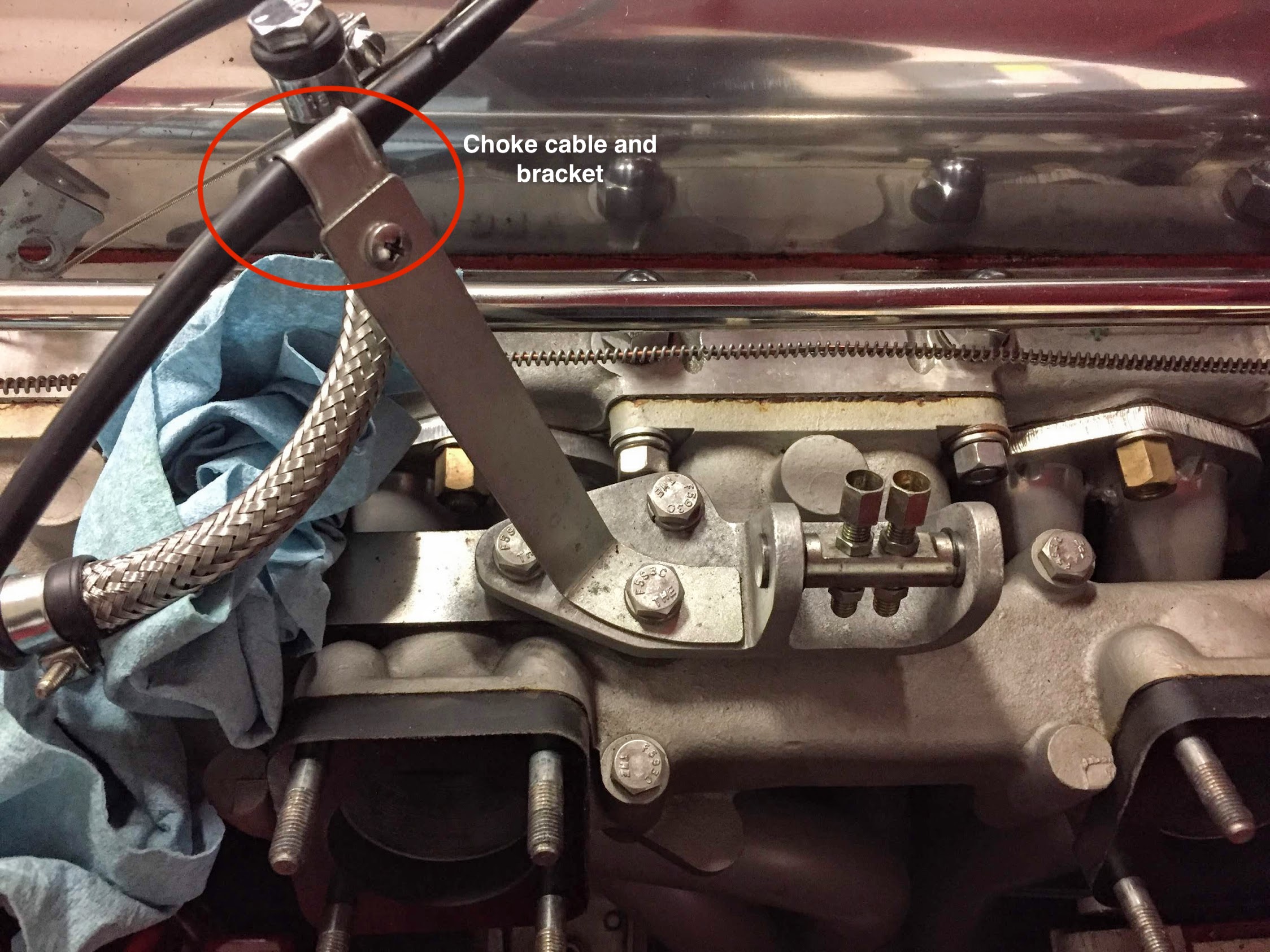
2:50 – Choke cable retaining clip
3:23 – A.C. Dodd HIF 44 modifications
5:33 – HIF 44 Hose fitting legend
5:39 – HIF 44 Throttle and choke cable connections
Setting up the HIF 44 for initial running is really quite simple. (more info to follow shortly!)
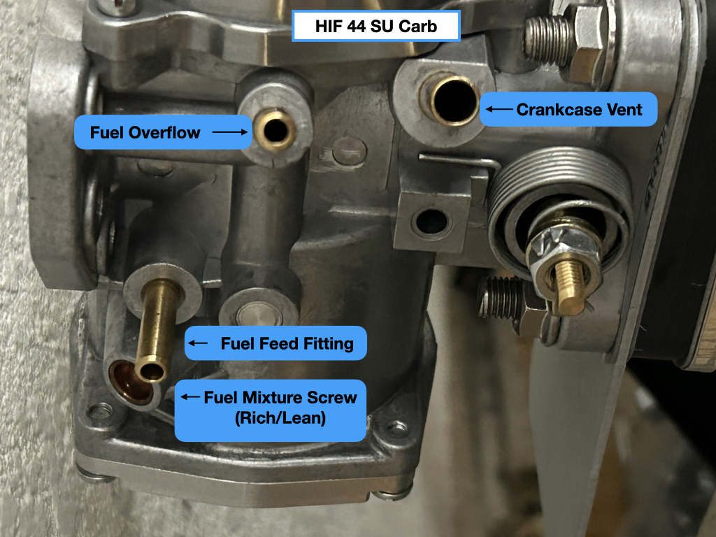
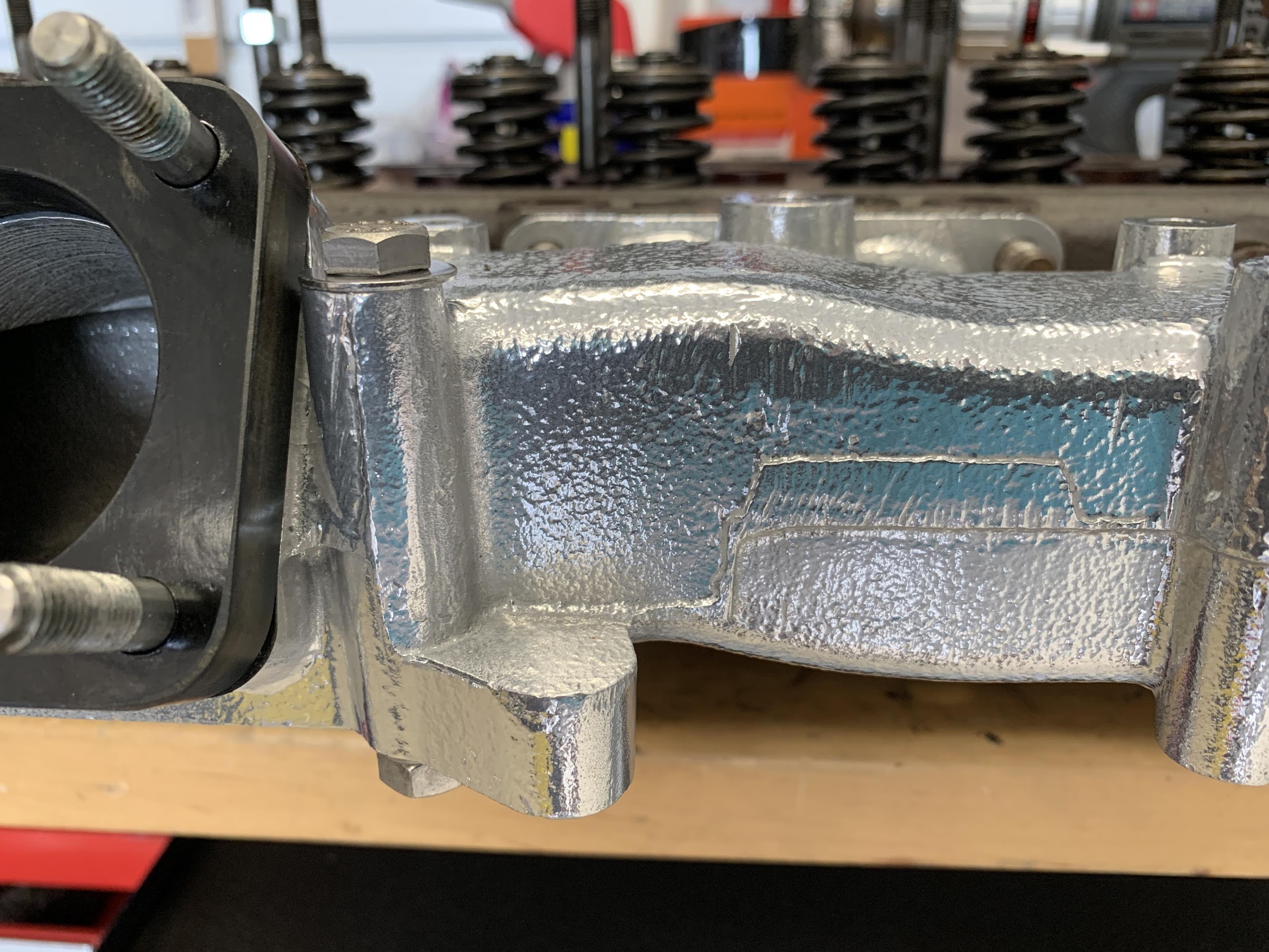
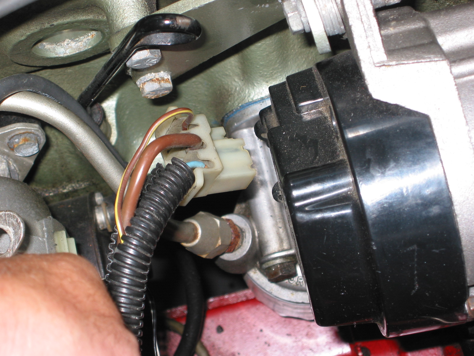
HIF 44 Carburetor (RH Side)
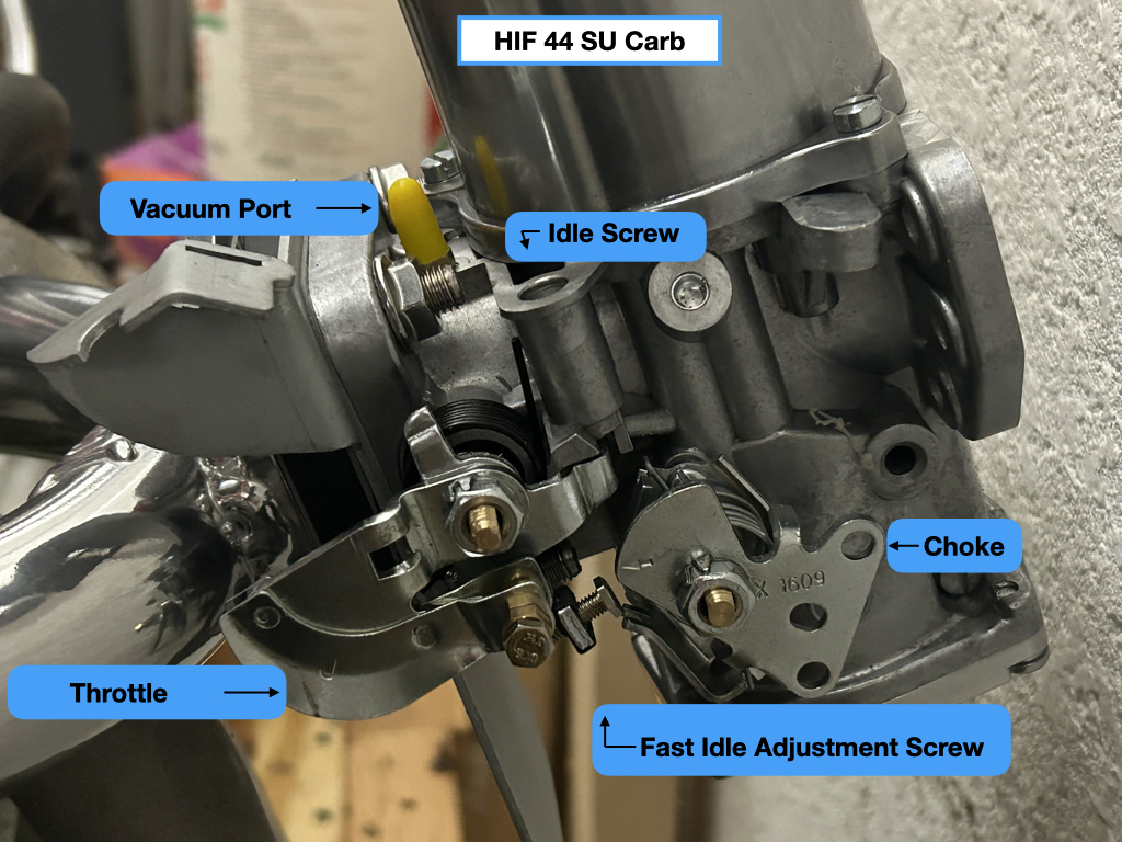
HIF 44 Carburetor (LH side)
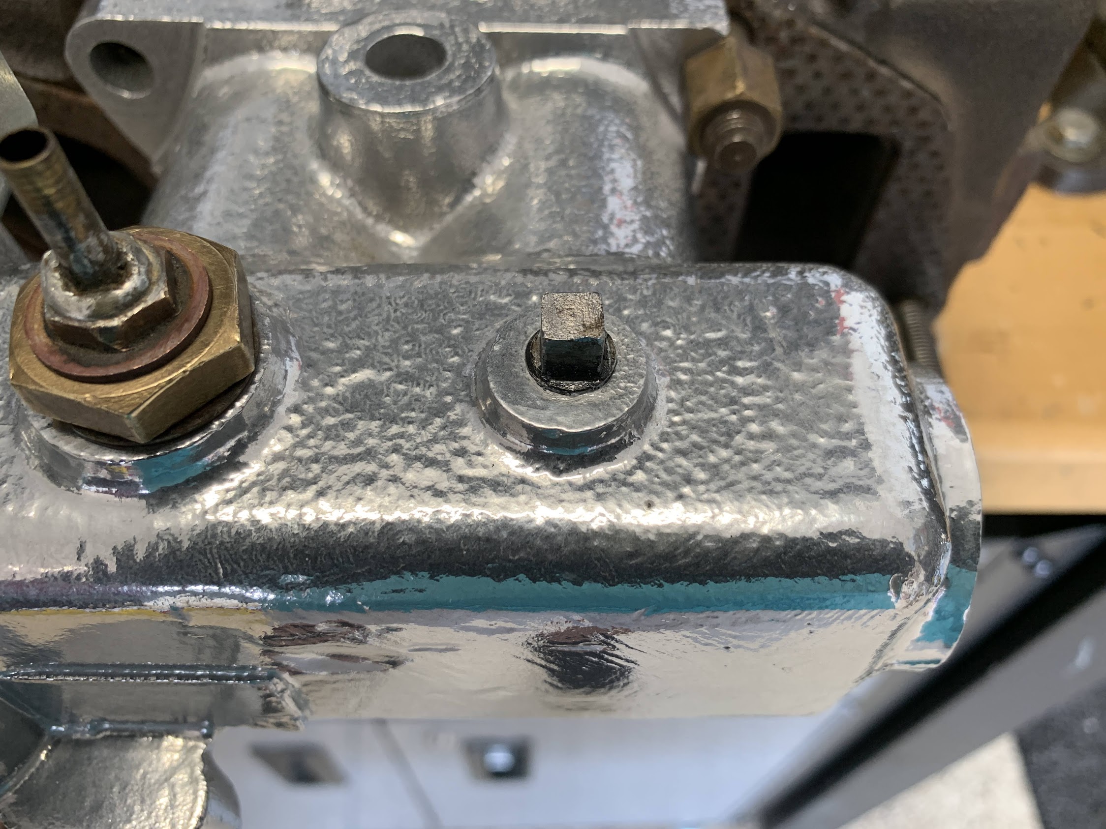
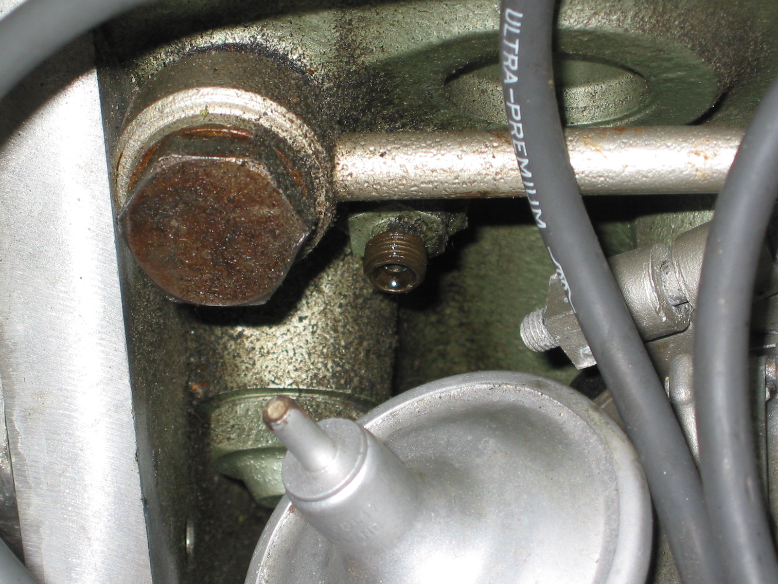
Setting the fuel mixture is the first step. This is accomplished by turning the fuel mixture screw shown in the image above. The image below shows the proper level of the jet:
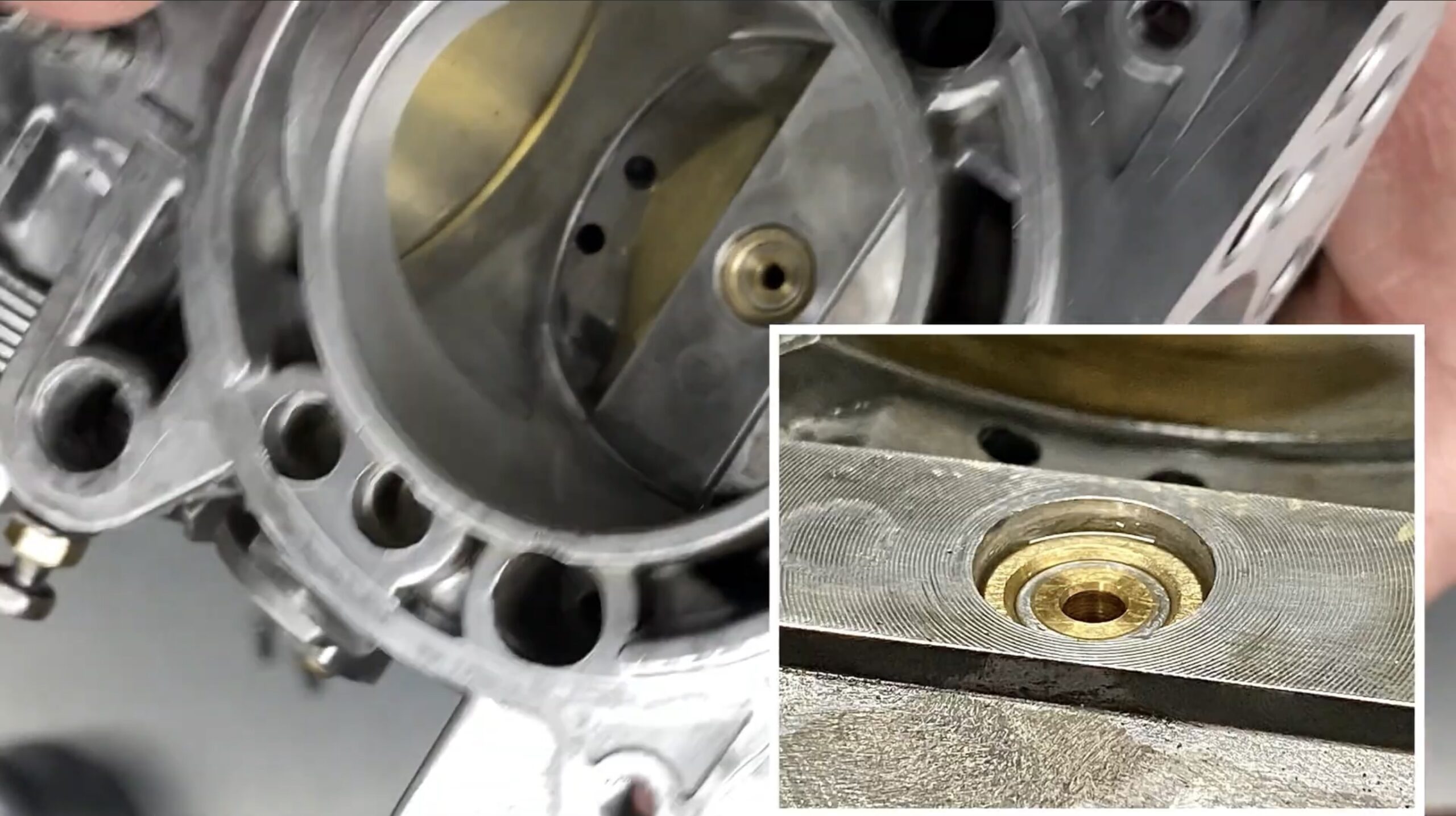
HIF 44 Proper Jet Height for Start-up
Turning the adjustment screw to the left will lean out the mixture by raising the jet thereby letting less fuel enter the manifold. Turning it to the right will enrich the mixture. This screw should only be adjusted to effect a change in the idle. It should not be adjusted to improve the drivability of the car at speed.
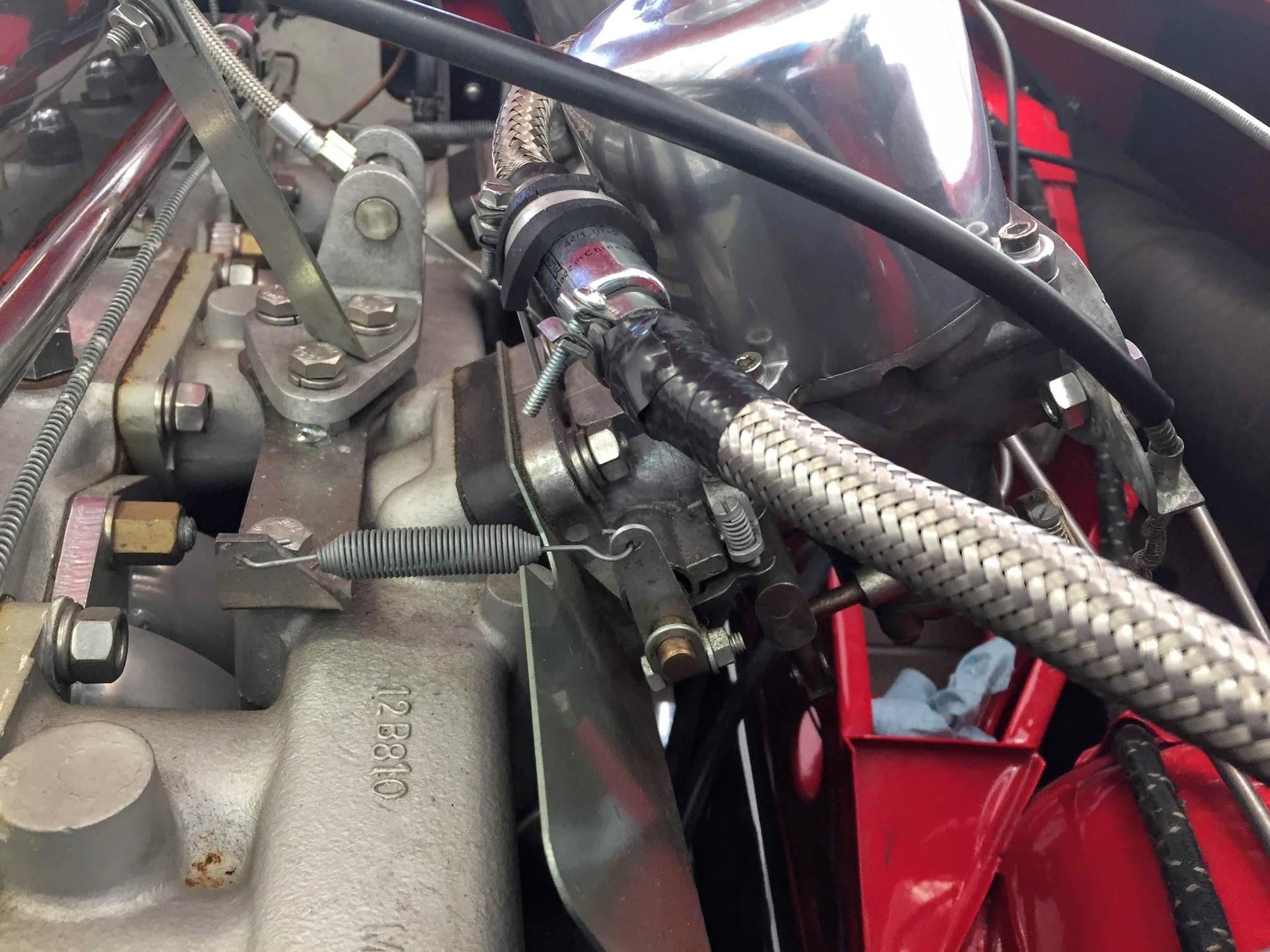
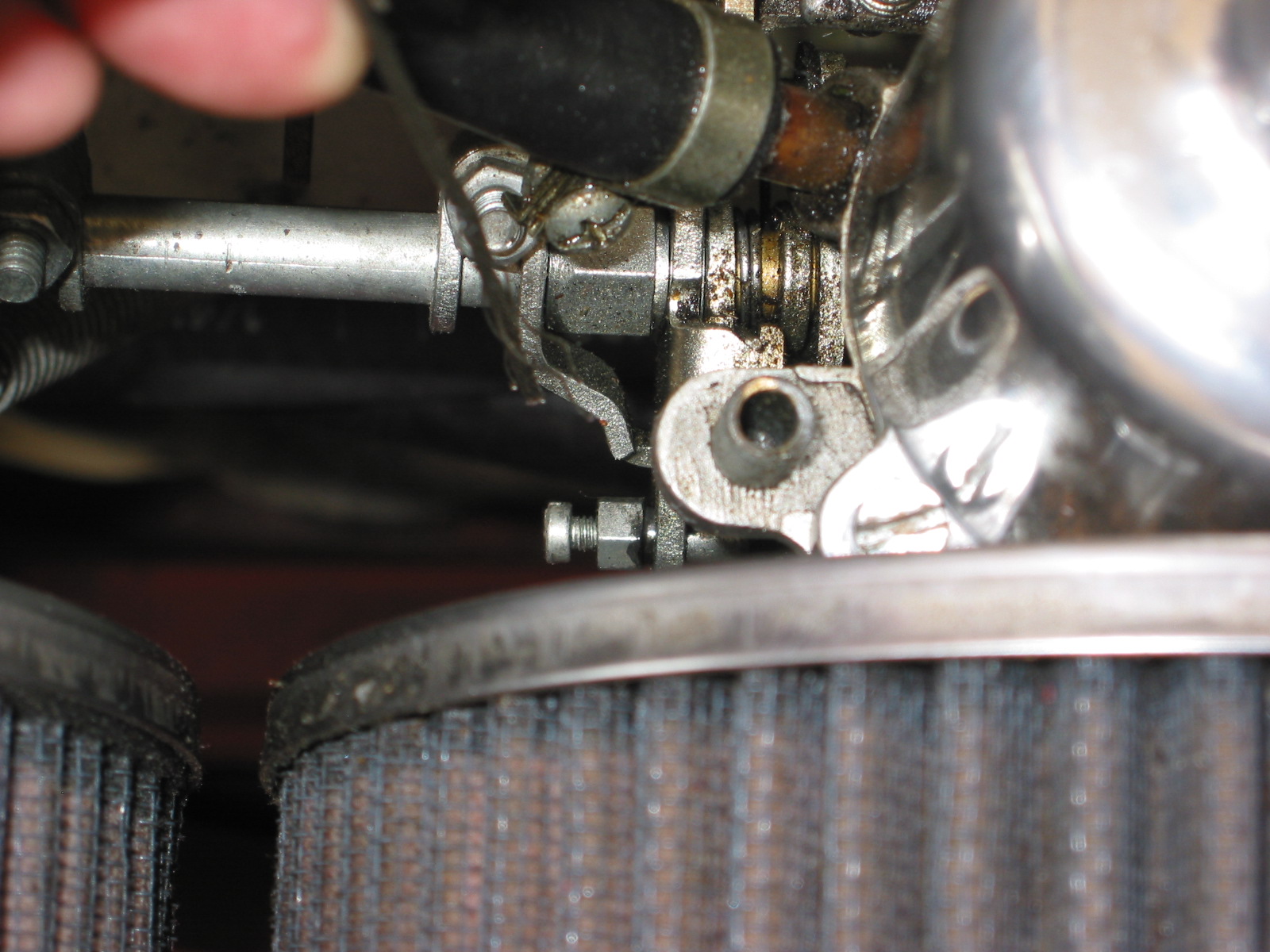
The fast idle, or choke, is set by adjusting the fast idle screw against the cam. The images below show the proper setting. The fast idea screw is turned down until it just touches the throttle lever. Once in that position it can be turned down one full turn. A feeler gauge with .018 blades is then inserted between the fast idle screw and the throttle lever. The choke lever is then rotated to line up with the center of the throttle adjusting screw. This is achieved by turning the adjusting screw until it just touches the arrow.
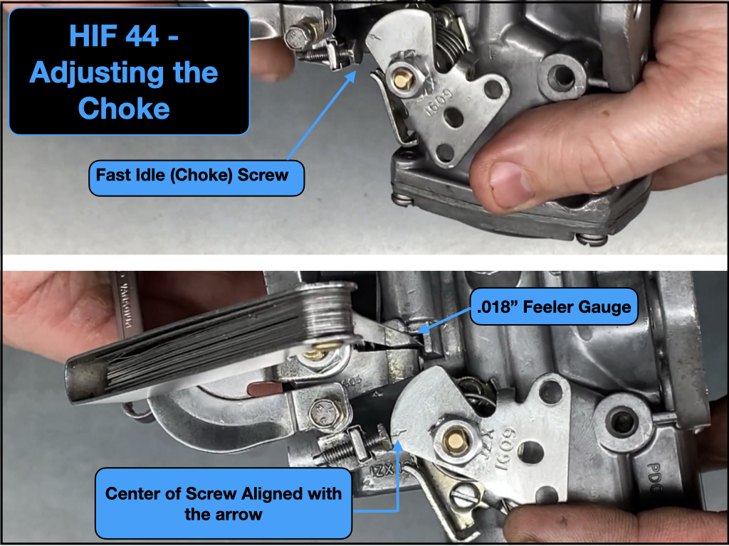
HIF 44 Adjusting the Choke
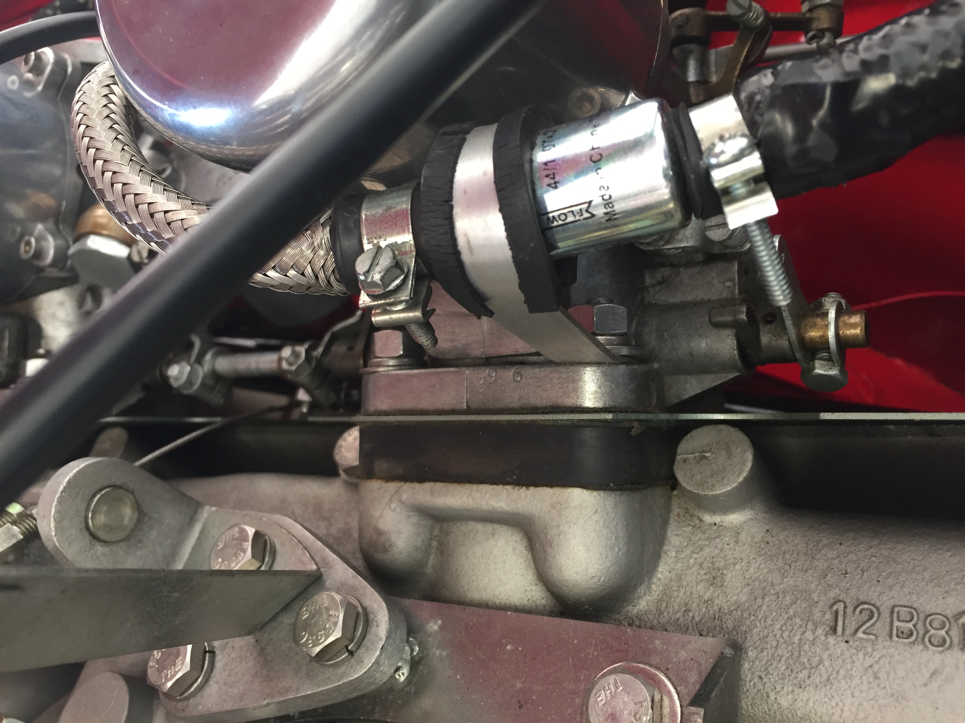
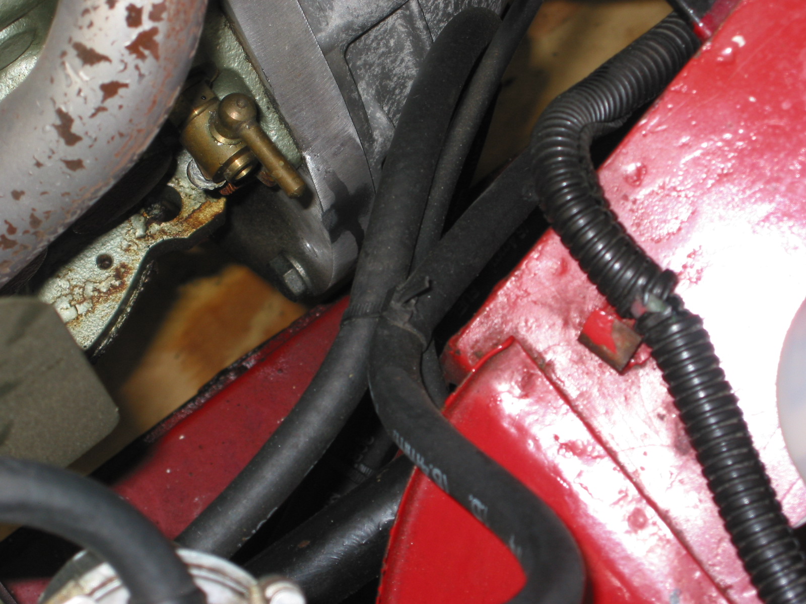
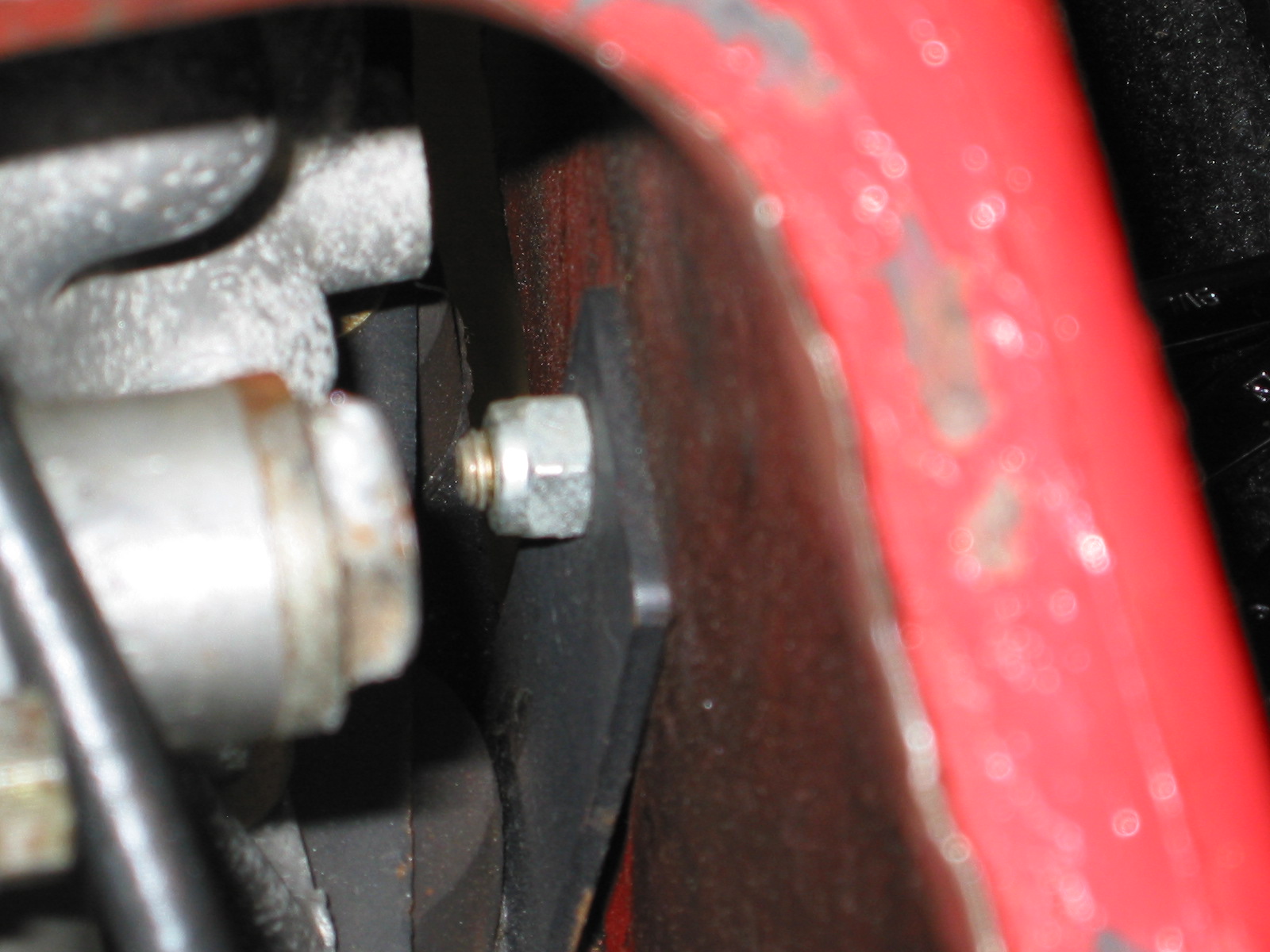
A small spring clip is used to secure the choke cable end fitting to the heat shield choke bracket. It is a friction fit and is just pressed down over the end of the cable ferrule.
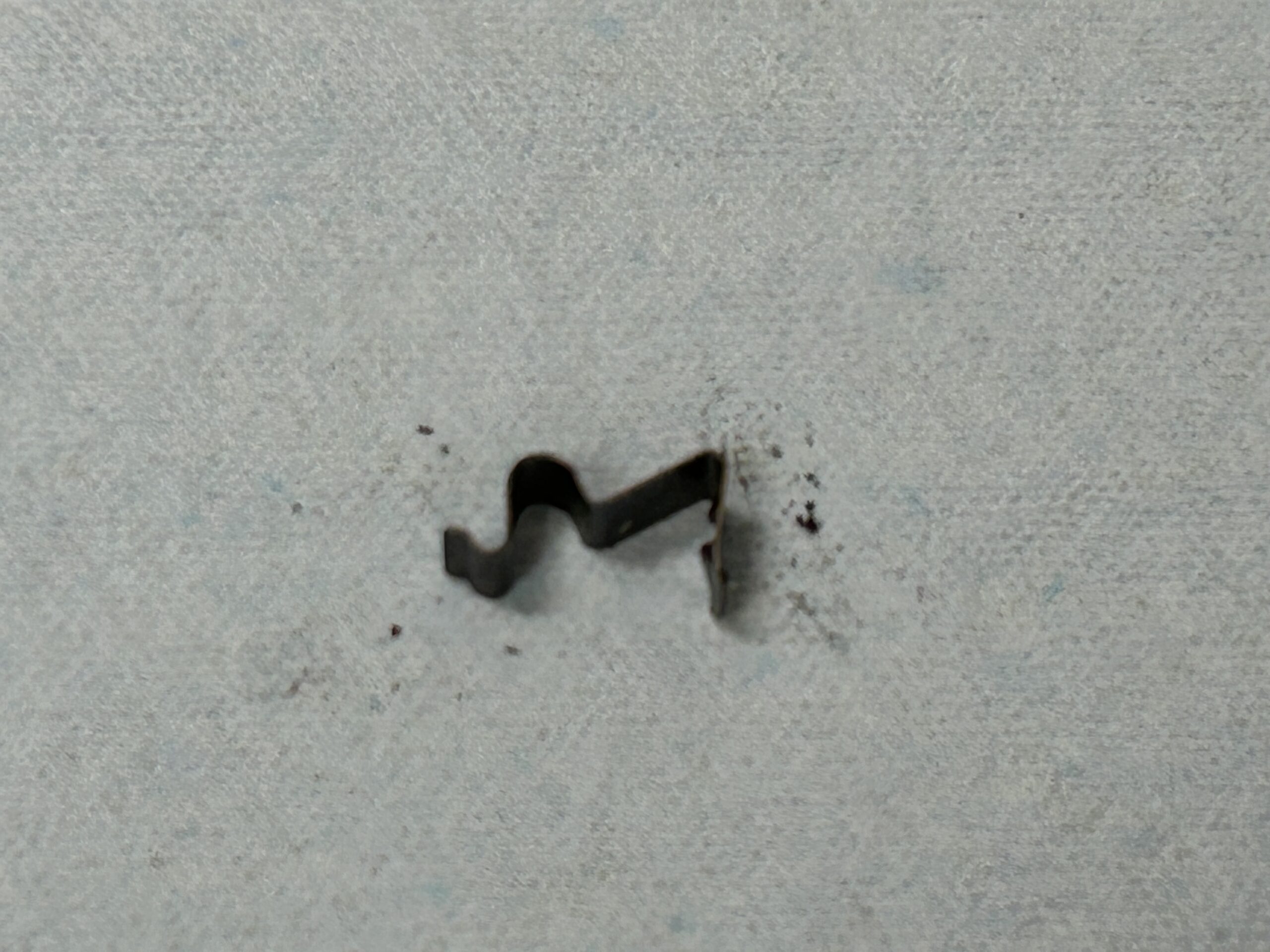
HIF 44 Choke Cable Clip
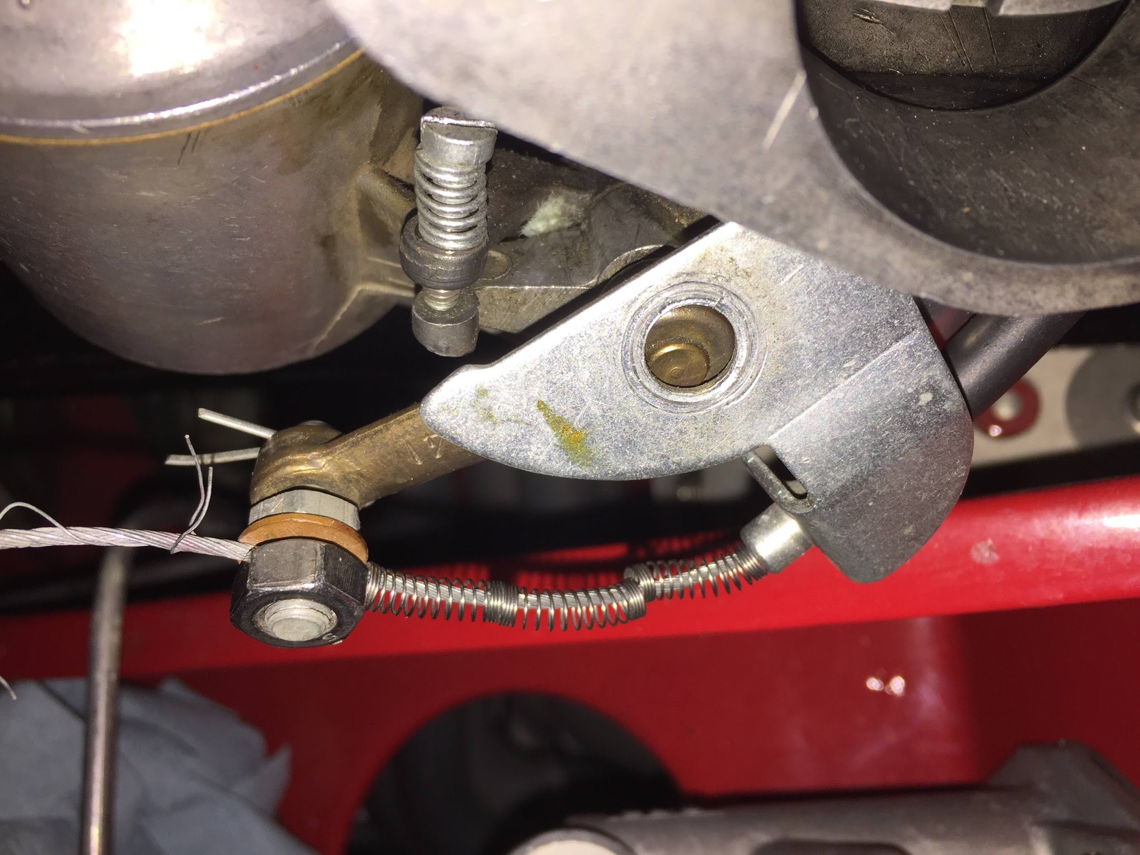
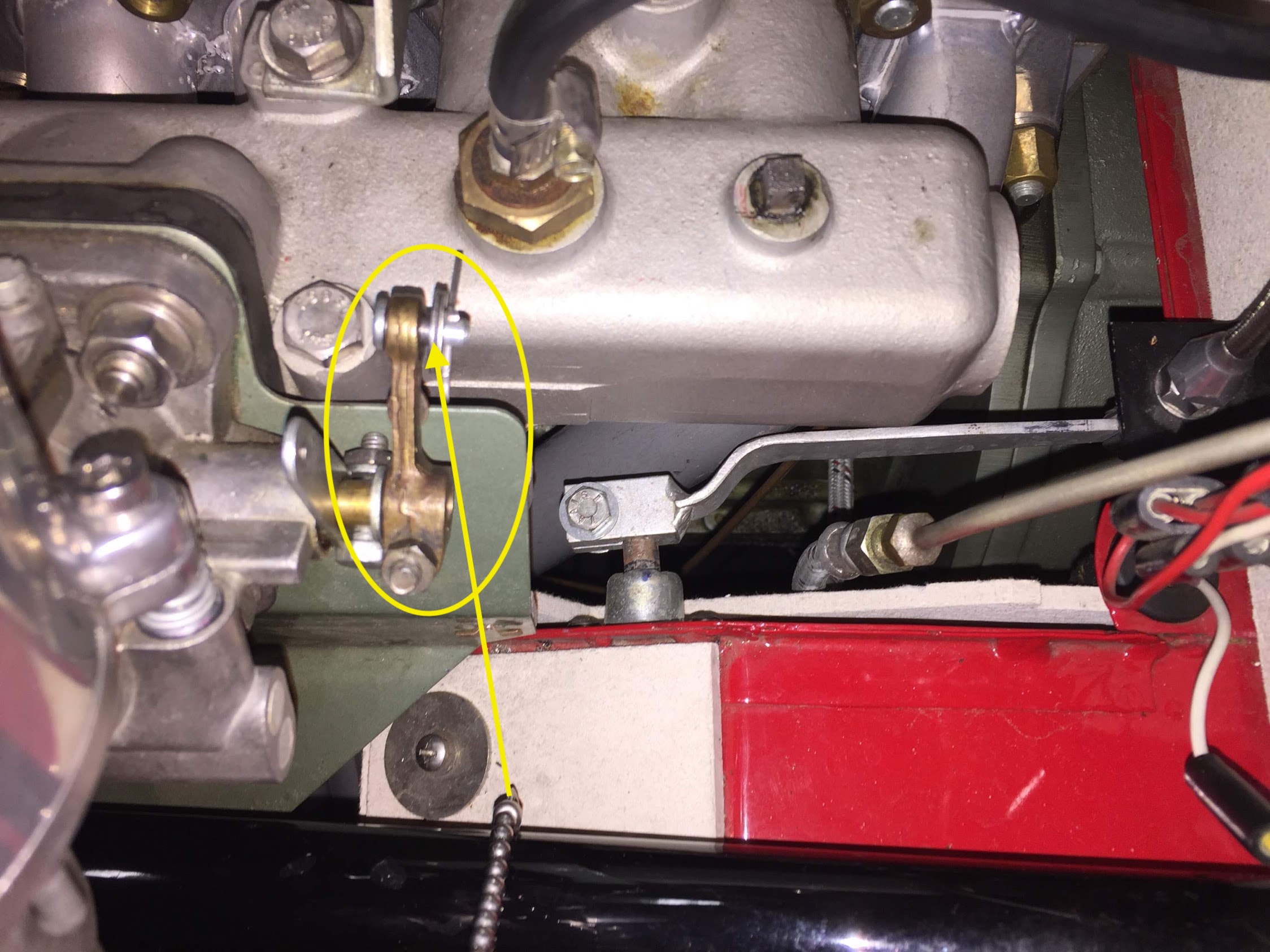
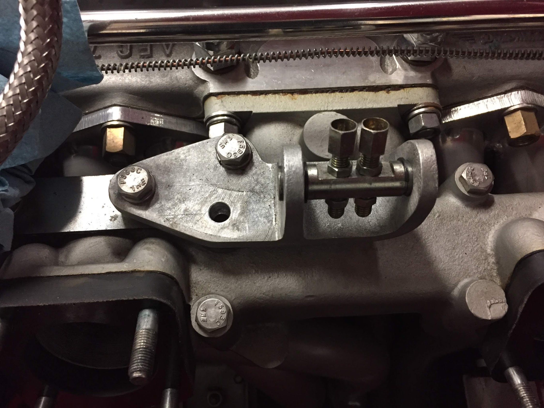
A two piece cable stop is used to secure the choke cable to the choke lever:
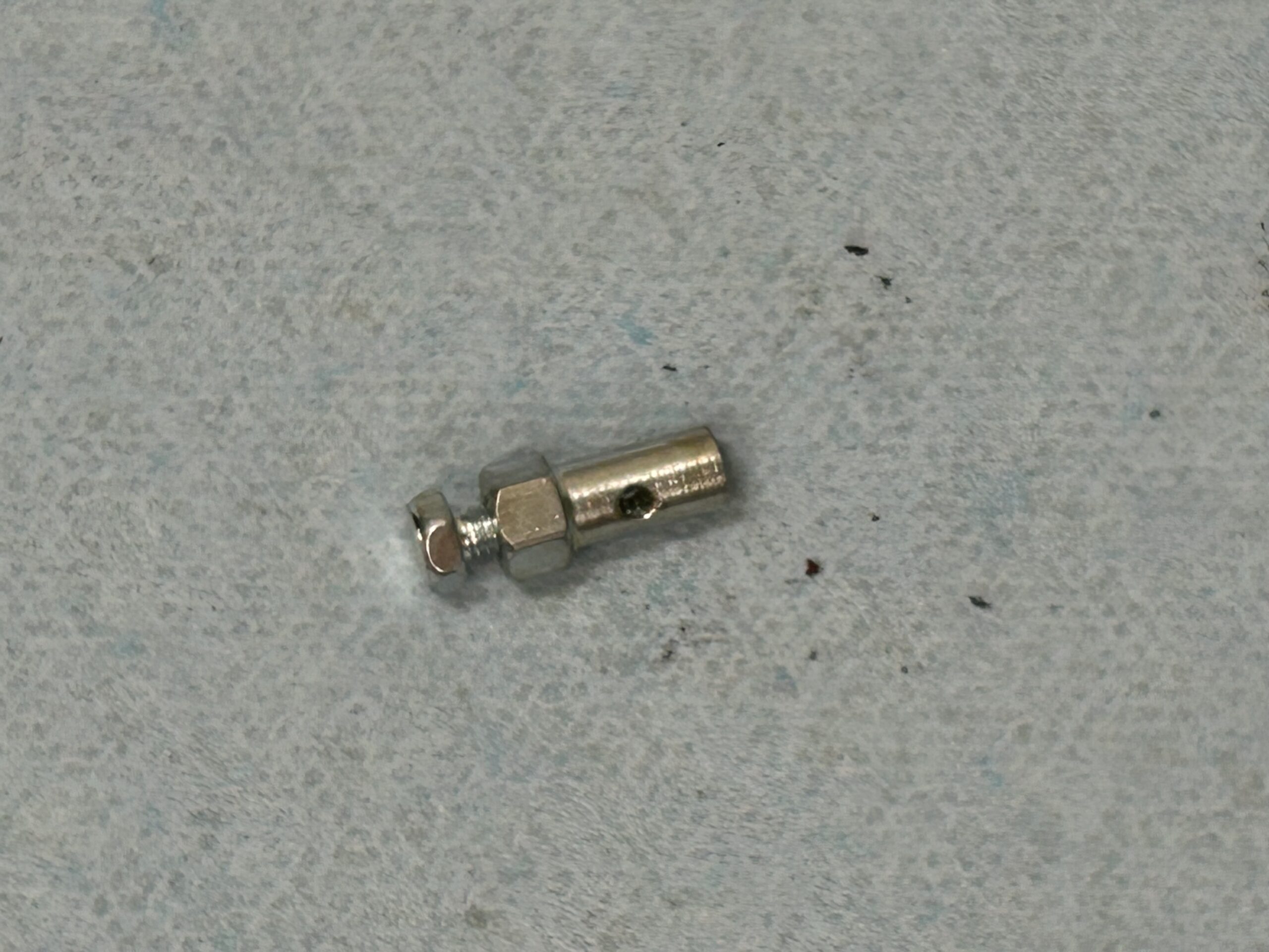
HIF 44 Choke Cable Stop
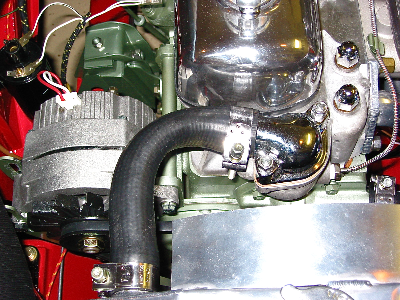
We also decided to improve air flow into the carb by installing an aluminum stub stack sourced from M.E.D. Engineering in the UK.
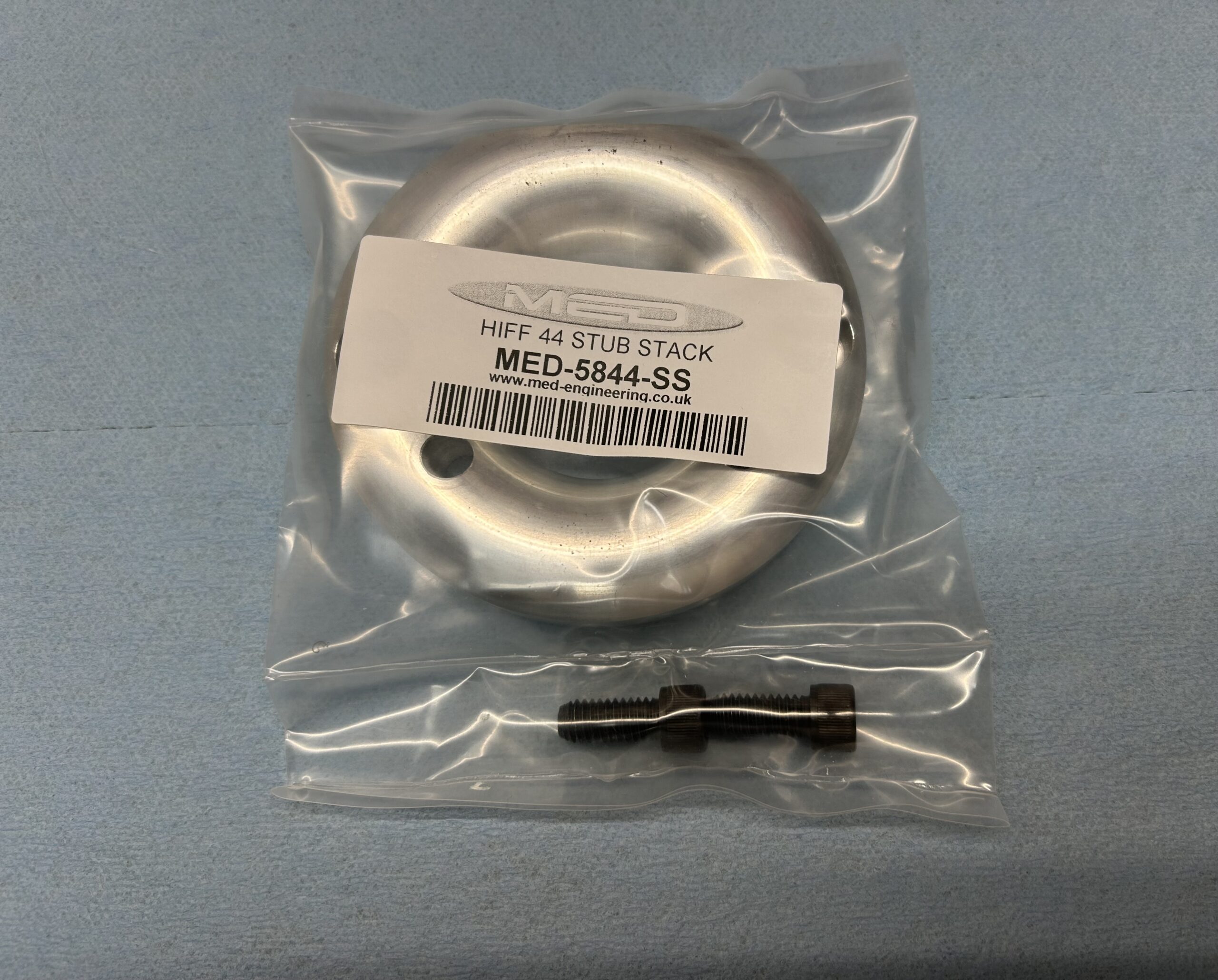
MED Stub Stack
Their site describes the billet stub stack this way:
The MED aluminum stub stacks have been extensively tested on our 110 Superflow flow bench to optimise the elliptical radius on the stub stack. The result is improved air flow to the carburettor/throttle body and a proven increase in performance – on a wide range of different engines and rolling roads.
The stub stack is temporarily mounted in this photo. Eventually the K&N air filter back plate will be installed first with the stub stack mounted inside the filter assembly.
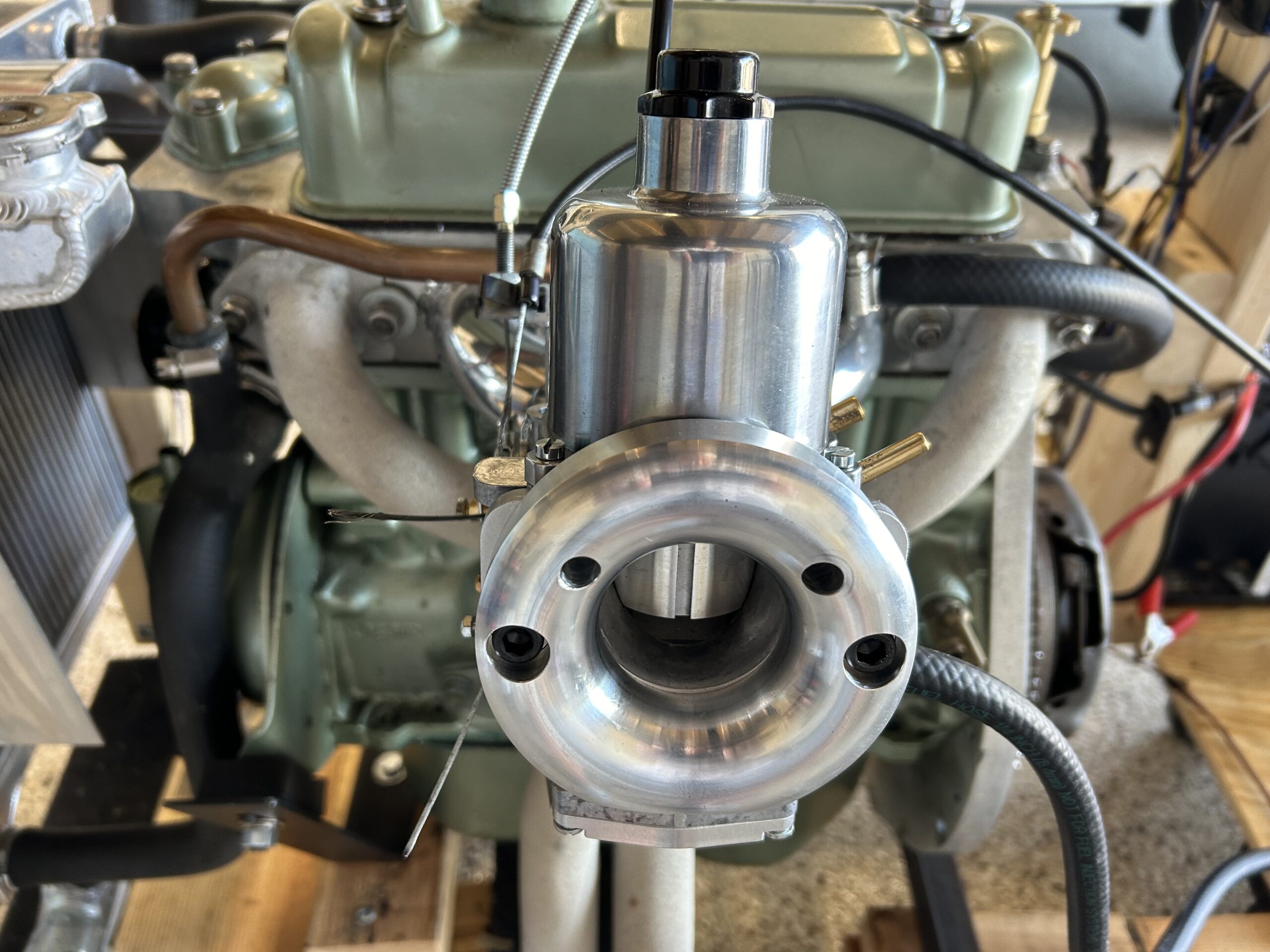
Stub stack temporary installation
Much of the tuning of the HIF 44 carb is accomplished through needle adjustment, spring choice and variations in damper oil weight. Our carb came with a BFY spring loaded needle. Upon initial running (but before we have connected an AFR gauge) the engine seemed to run well at higher rpm but lugged a bit at idle and required the use of the choke for longer than expected. We wondered if the BFY needle was the cause of insufficient fueling at idle, so we decided to try a BDL needle.
The .100″ jet needles (the middle needle below) are measured in 16 increments:
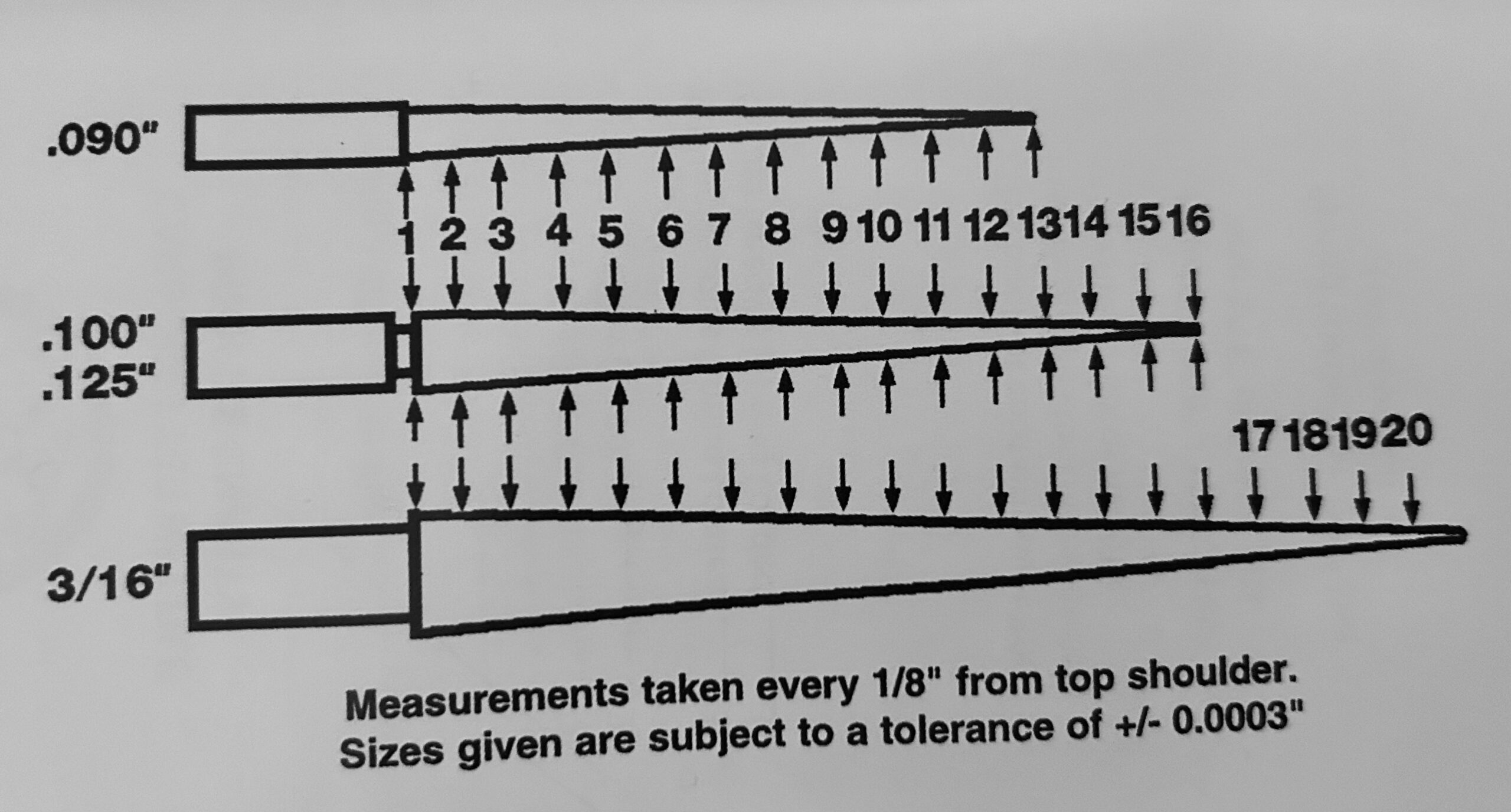
Needle Metering Increments
The following chart depicts the difference between the BFY Needle and the BDL Needle. As can be seen, the needles are very similar. The only differences are in positions 2,3,4 and 5. This should leave us with a slightly richer condition at idle and maintain the same fuel condition in the higher rpm range. Hopefully we will not need as much choke this time. Additional running will tell us if we have improved our running at idle or not.
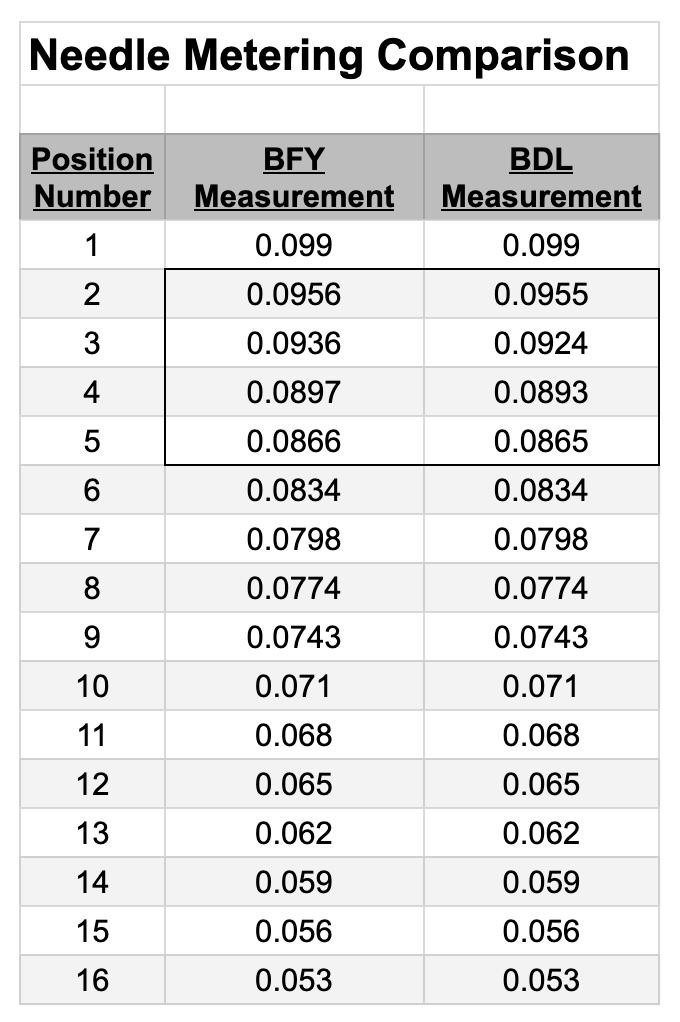
BFY and BDL Needle Comparison
Finally, we are using a K&N Cone-type air filter for the carburetor. We sourced this one from Moss Motors:
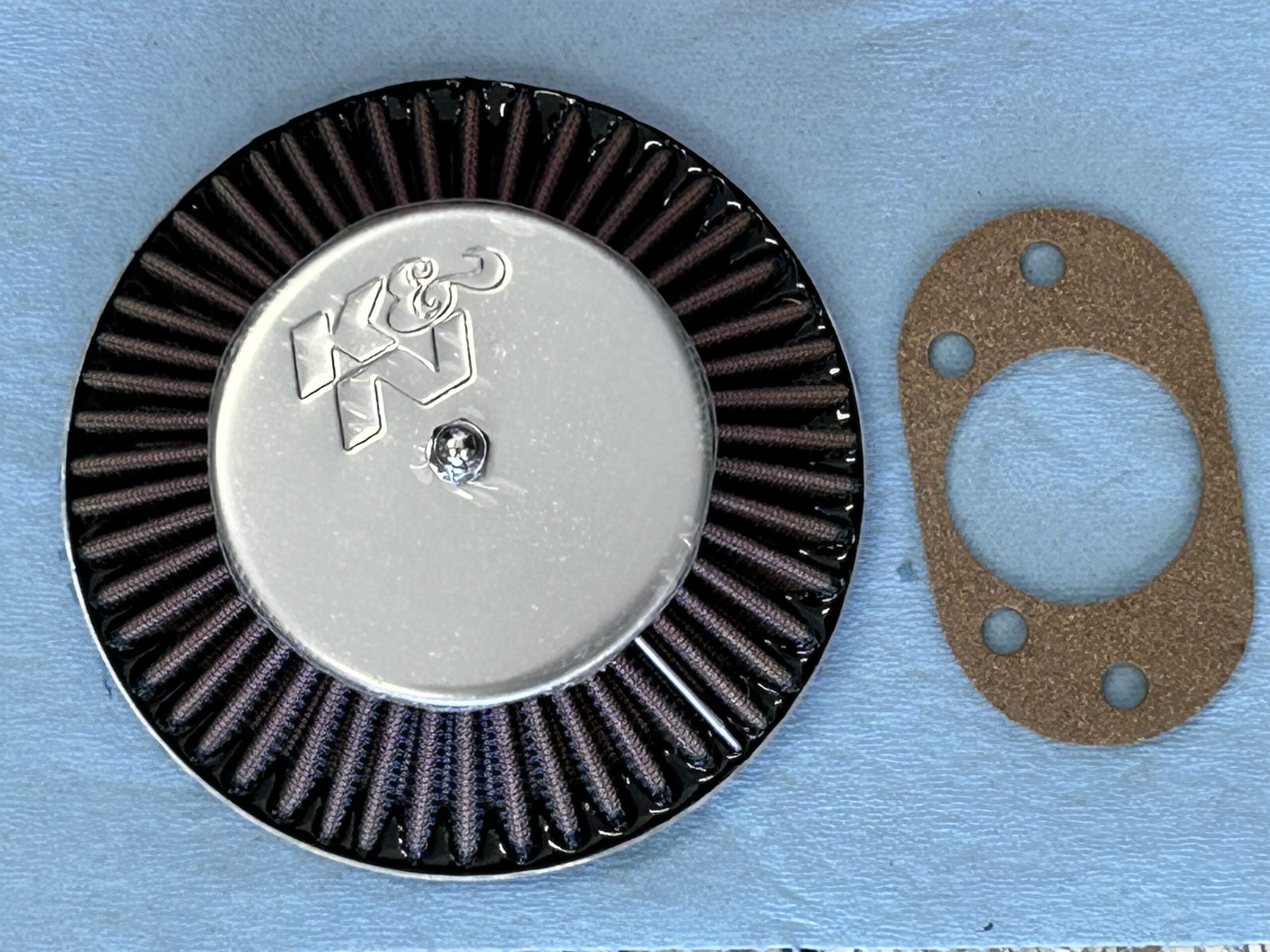
K&N Air Filter
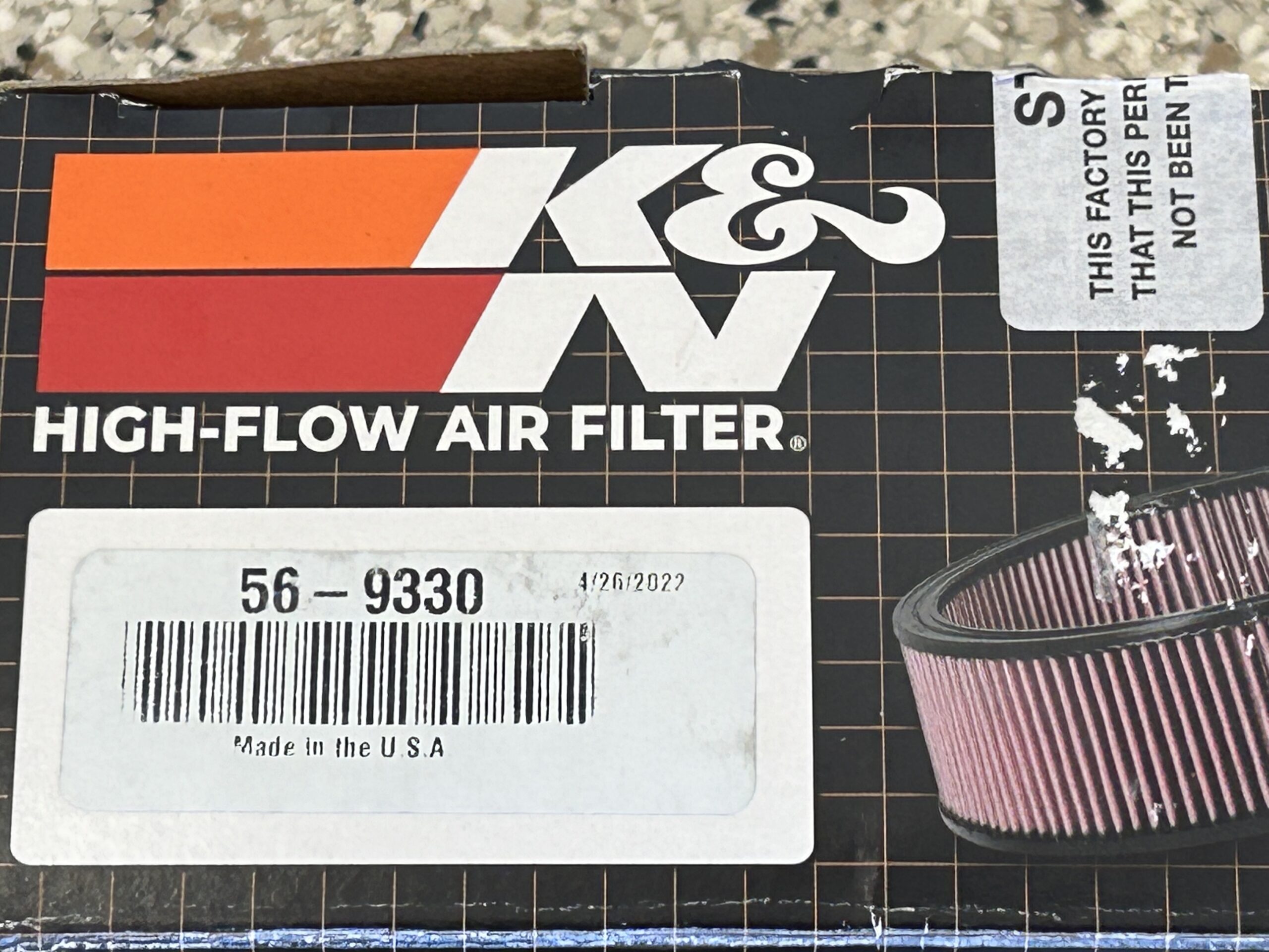
K&N Filter Packaging