As has been stated previously, our plan is to start the engine and getting it running reasonably well before we put it back in the car. We were experiencing an oil leak from the front of the engine and suspected the timing chain cover or the crank seal, so we decided to pull the cover and replace both the gasket and seal. While we were at it we freshened up the paint and upon reinstalling the cover we used a custom reinforcement plate for the cover that serves to spread the load evenly to create a better gasket seal.
One has to remove the water pump fan pulley to loosen and remove the fan belt. Alternatively, the same could be accomplished with slacking off the alternator but in our case the water pump pulley was easy. The tab on the crank bolt tab washer was bent back and an impact driver was used to loosen the bolt. After the bolt and washer were removed the pulley slipped right off.
The 1275 “A” series engine originally came with a crank pulley but at some point in time that pulley was replaced with an harmonic balancer that is commonly sold by the major parts vendors. The balancer has a rubber component that helps with vibration and it is, obviously, balanced. Evidence of the balancing is clear in the drilling of the balancer face. The harmonic balancer is deeper than the original pulley which results in the tab washer not having any purchase or key to retain it. To compensate, there is a flat on the balancer face that permits the punching downward of the washer face to create a flat to prevent rotation. This is demonstrated in the accompanying video.
A combination of 5/16″-24 and 1/4″-28 hex bolts with lock washers is used to fasten the timing cover to the engine.
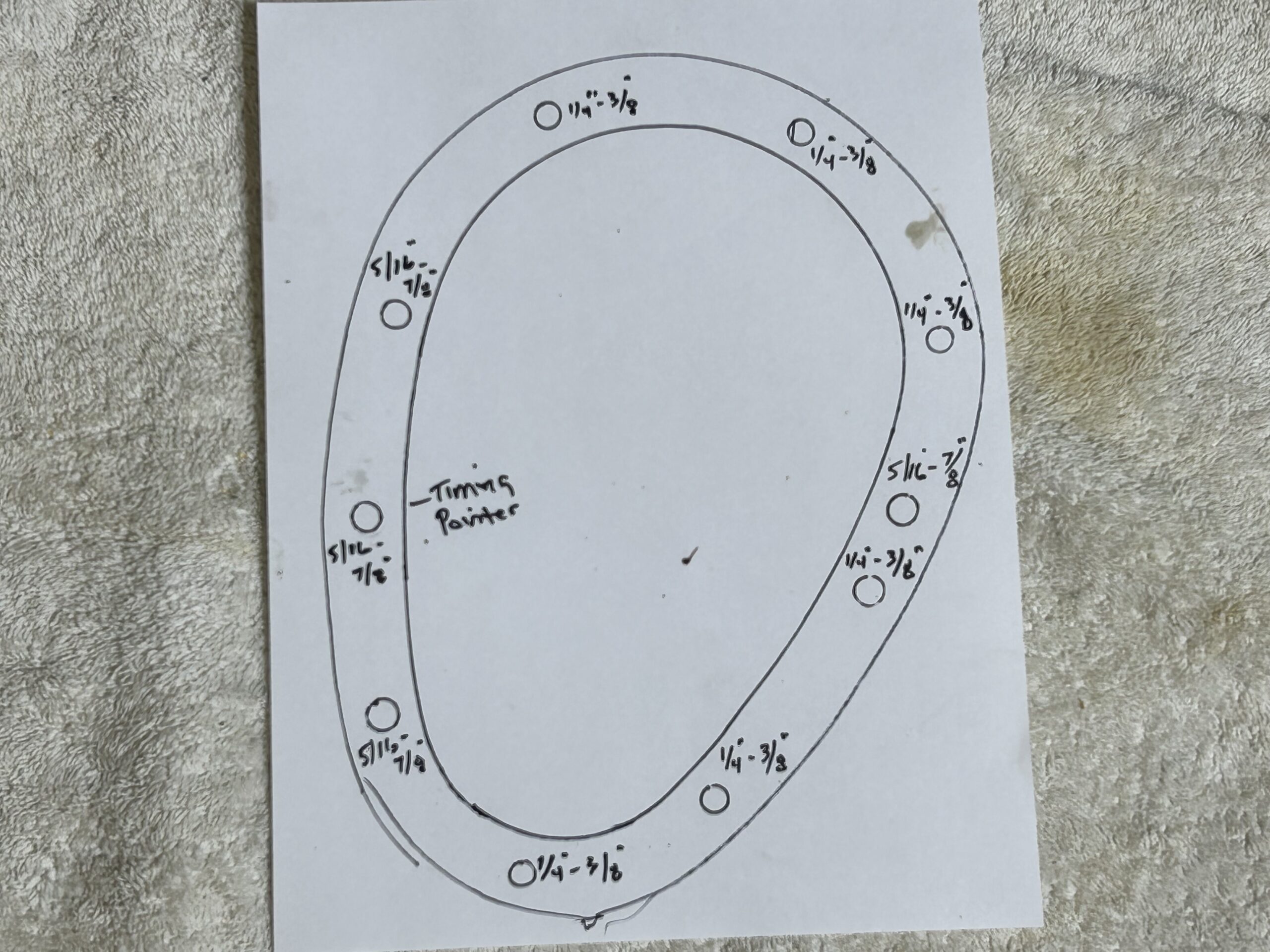
Timing Chain Cover Mounting Bolts
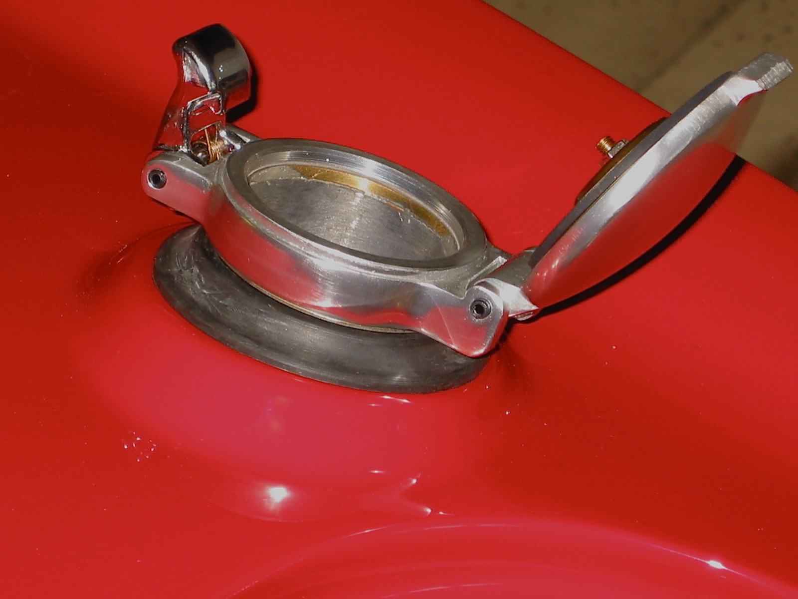
The video also shows the “massaging” of the bolt holes in the face of the timing chain cover to ensure a flat surface before mounting to the engine. A steel flat edge is used to determine that a flat face is realized. The old crank shaft seal was removed and a new seal was installed with the open “spring-side” of the seal toward the engine. A light smear of oil on the seal was all that was required and it was tapped into place with a piece of wood and light hammering. The face of the engine was carefully cleaned with a razor blade and brake cleaner.
The oil slinger was never removed but if it is in your case, it should be reinstalled properly. There is an “F” stamped in the face of the slinger and it faces “front” toward the radiator – away from the engine.
The gasket was then secured to the cover with Gasgacinch and a black RTV was lightly used on the face of the gasket to the engine. A couple of the upper short bolts were then loosely mounted and the cover was lightly pressed against the engine face. Before tightening the cover the pulley was reinstalled on the crank shaft and the cover was adjusted a bit to ensure that it was centered.
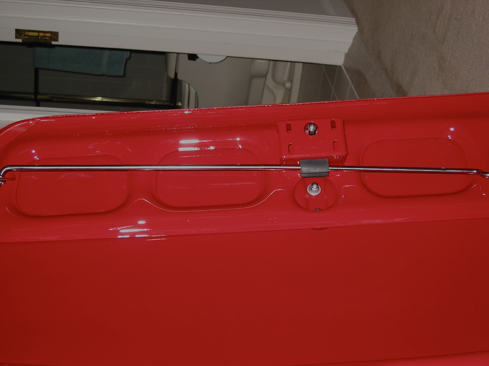
The timingchain cover reinforcement plate sourced from John Howell at Britcarfixes https://www.britcarfixes.com was then installed. This is a very nice high-quality product with very complete instructions.
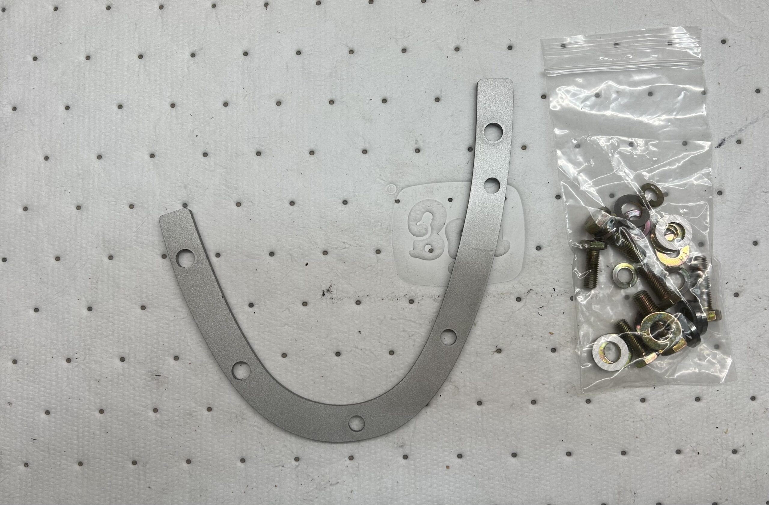
Britcarfixes Reinforcement Plate
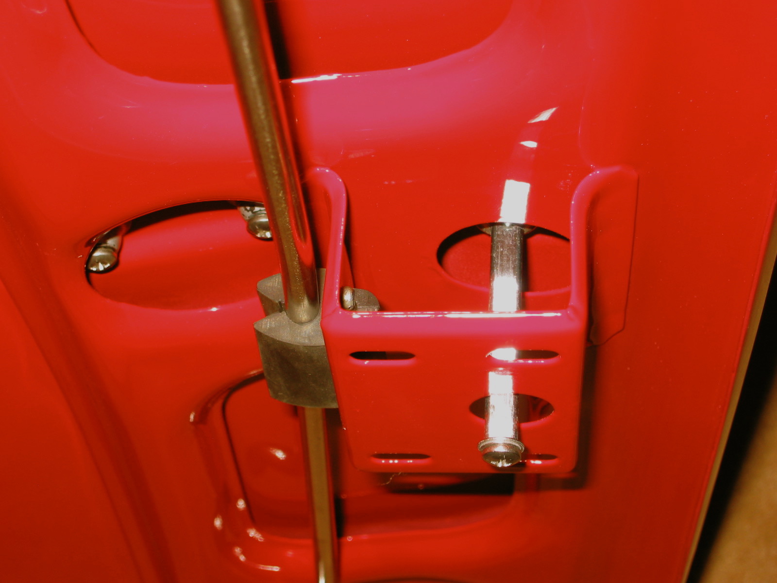
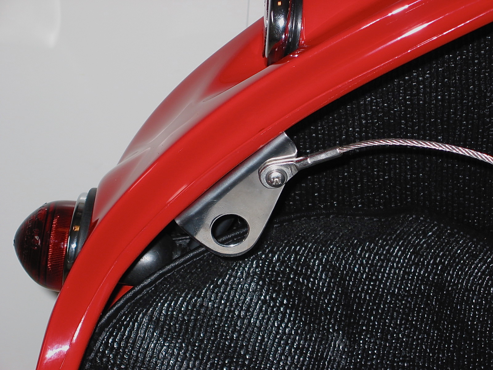
We found it easiest to put a little grease on the bolt spacers to hold them to the face of the cover and we could then easily hold the plate in place and insert the mounting bolts. Our ignition timing pointer was used in place of the bolt supplied by John. After wiggling the cover again to make sure it was centered on the crank shaft, each of the bolts was tightened by hand and the torqued to 8-10 ft. lbs.
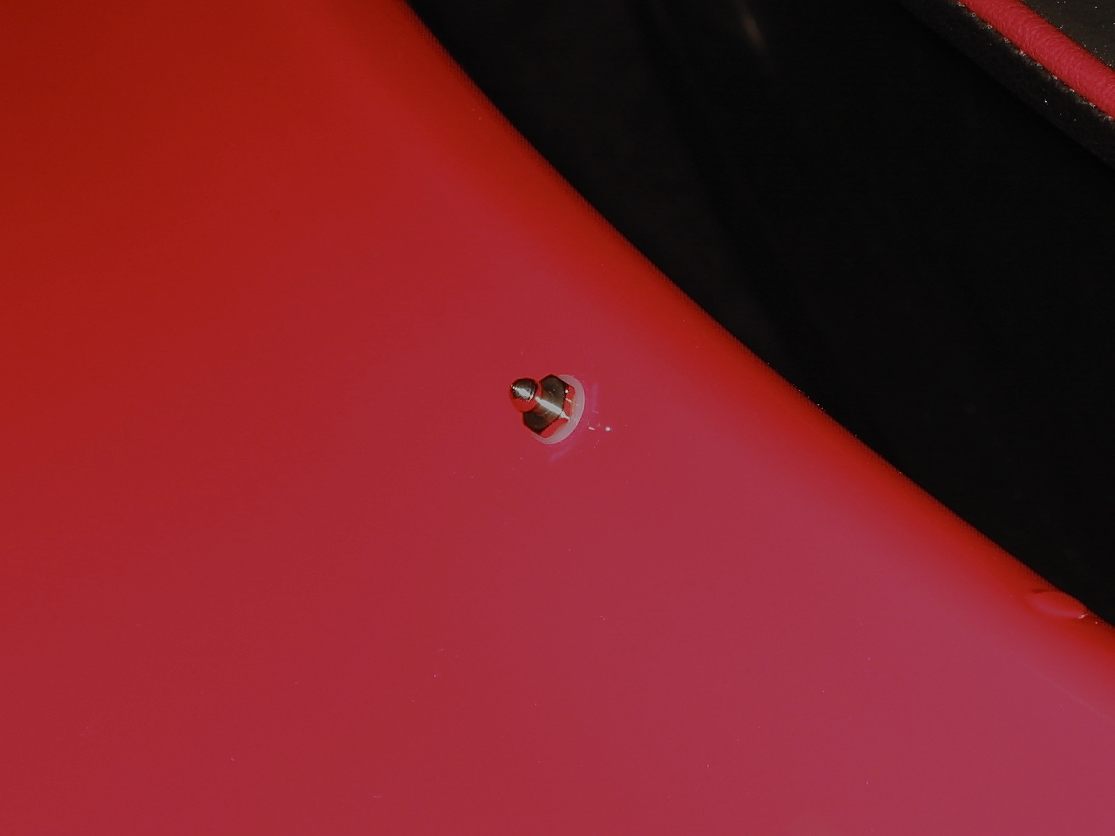
The harmonic balancer tab washer was then reinstalled and the crank bolt was finger-tightened to the crank. The tab washer was then wiggled a bit to ensure that it was centered on the lip of the bolt and the bolt was then tightened to 70 ft. lbs. To do so, we removed the starter and slid a pry bar between some teeth in the ring gear of the flywheel. This held the crank in place while we tighten to the 70 lbs.
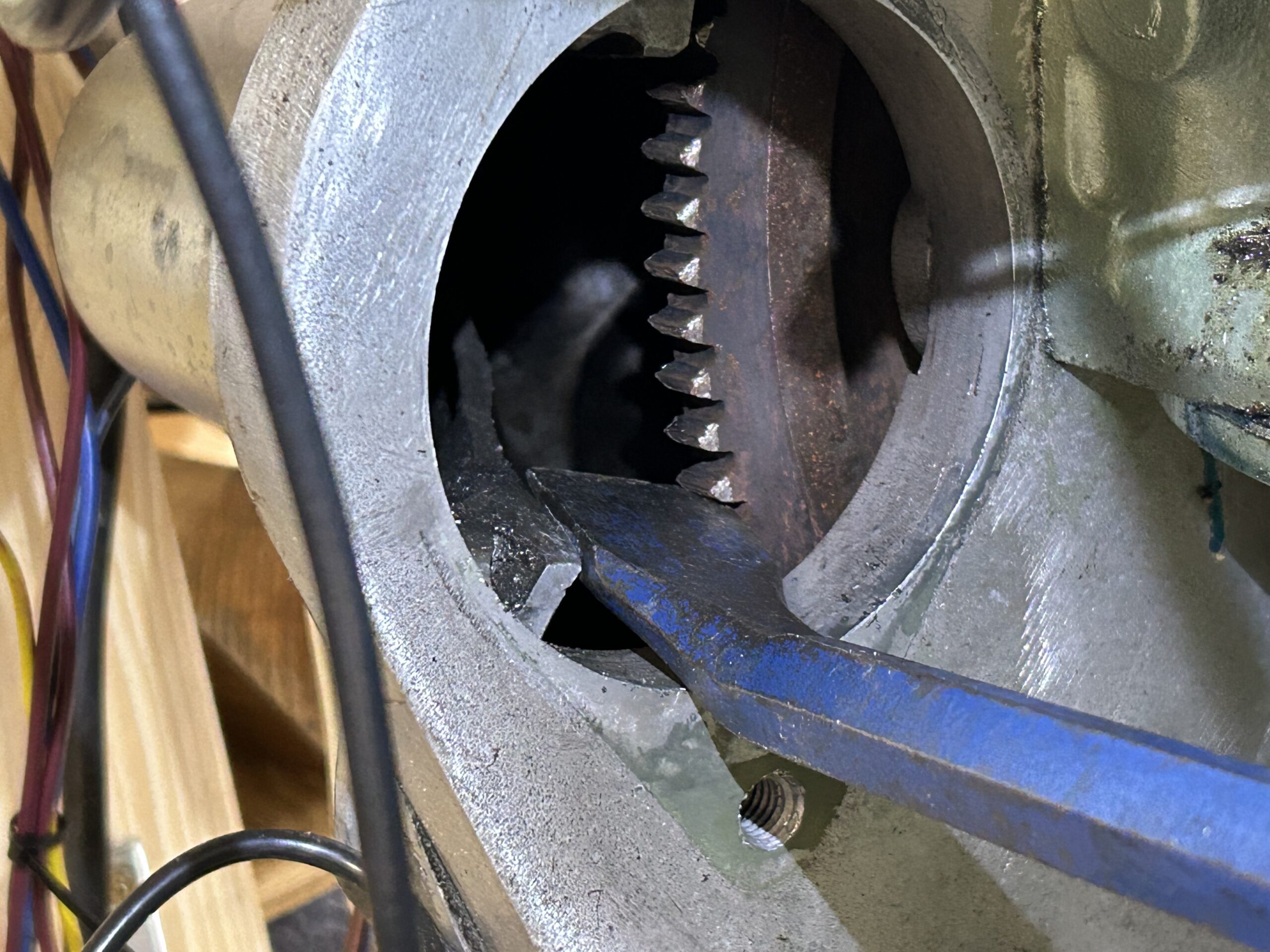
Holding the flywheel to prevent crankshaft turning
We then used a punch and hammer to press down the washer along the harmonic balancer flat (pointed out in the video) and then used a chisel to bend part of the washer up against a flat on the bolt to keep everything in place. Finally, we reinstalled the water pump fan pulley, the fan belt, the radiator and its hoses and the electric fan.
The following Bugeye Restoration Video Episode Forty-seven shows the process involved in replacing the timing chain cover gasket and crank seal:
https://vimeo.com/867751162/aeb5d81346?ts=0&share=copy
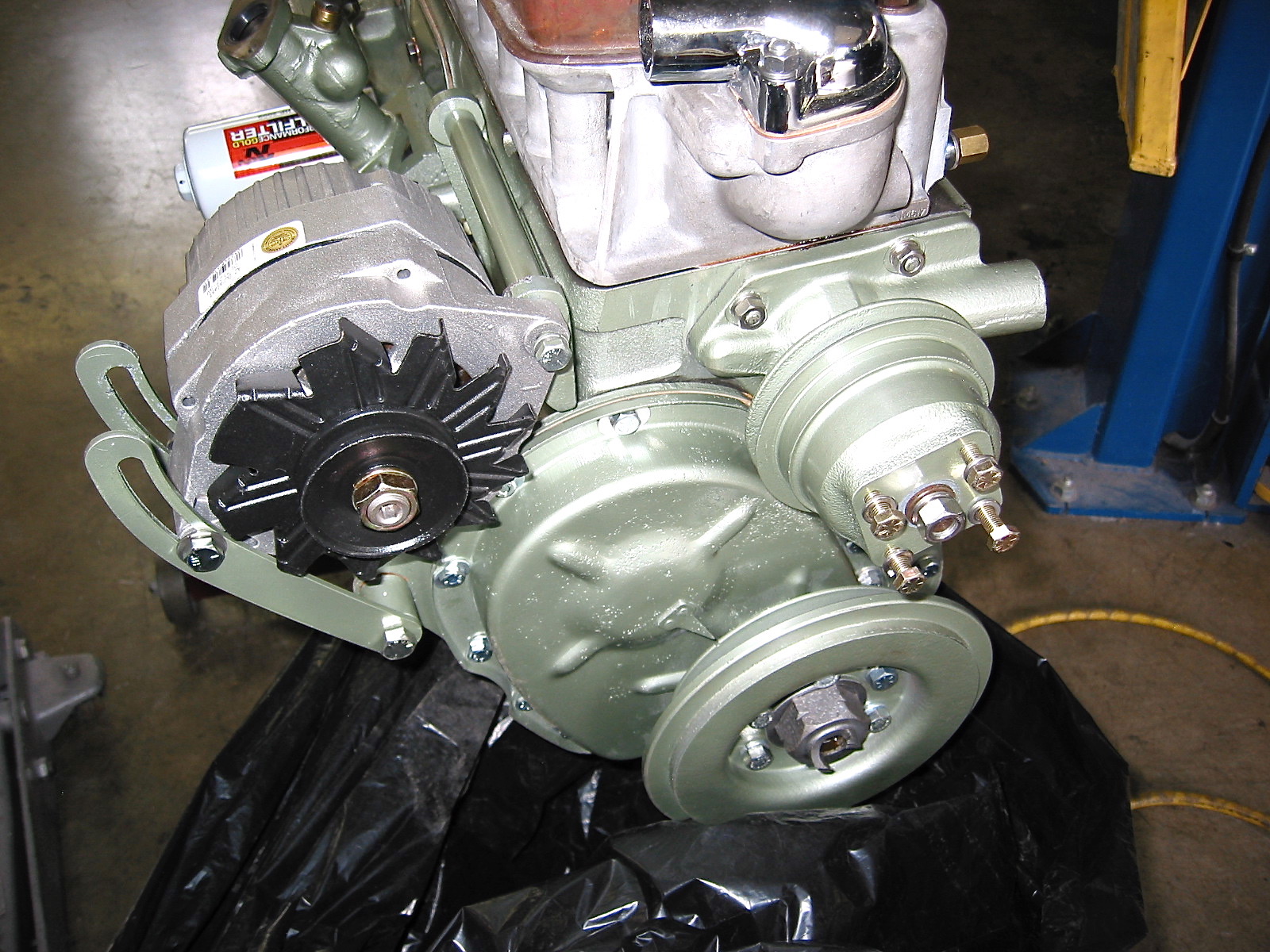
Moving on to Fueling and Ignition
Next we moved on to some other aspects of preparing the engine for starting. To use the single HIF 44 carburetor we obviously had to change the intake manifold and that was sourced from Maniflow in the U.K. https://maniflow.co.uk/index.php?view=category&category=162
This particular manifold must be used to lower the carb thus preventing it from conflicting with the Sprite bonnet when closed. After receiving the manifold, we sent it to Jet-Hot Coating https://www.jet-hot.com/thermal-barrier to receive their classic ceramic finish and it looks amazing!
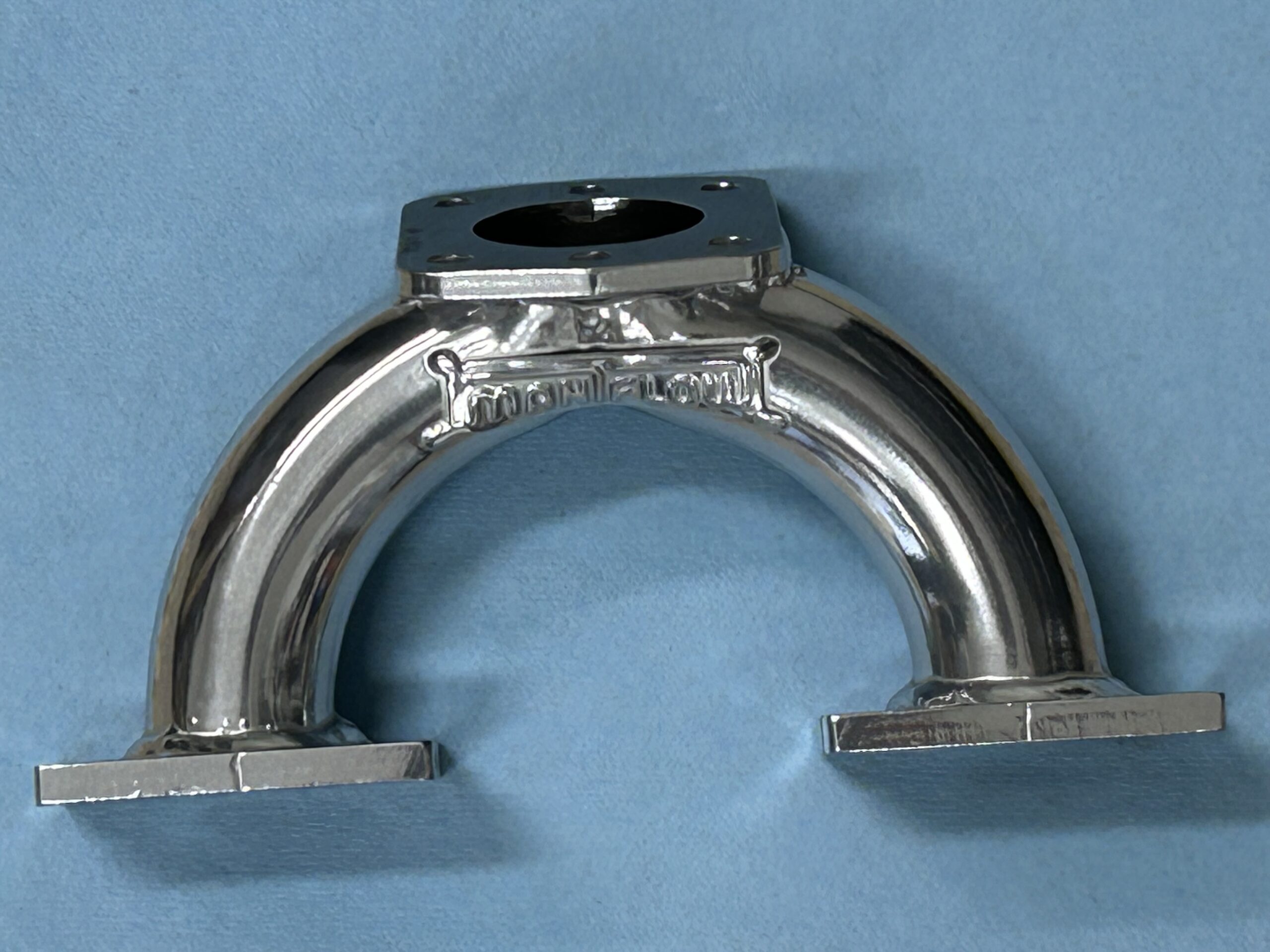
Maniflow 1 3/4″ Intake Manifold Jet-Hot Coated
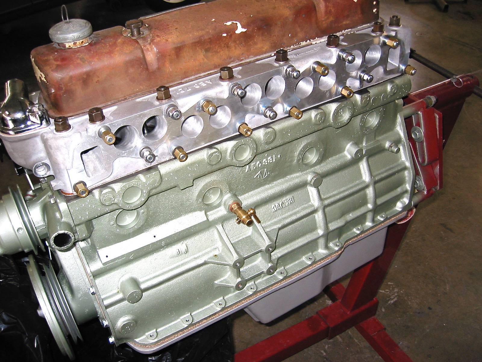
Just to see how things will look we installed the new intake, the tired exhaust headers (that will get the Jet-Hot treatment eventually), as well as the carb heat shield, gaskets and spacer. These will be featured in a future video that will be included in this post once we receive the carb from the U.K. As shown in the photos below, the sequencing order of the gaskets, spacer, and heat shield is incorrect but will be changed before the carb is mounted. The proper sequencing beginning at the manifold is gasket, phenolic spacer, gasket, heat shield, gasket, carb.
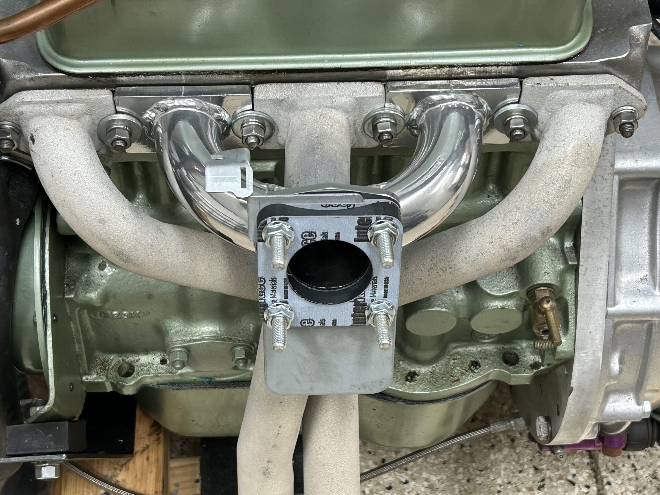
New Intake Assembly Mounted
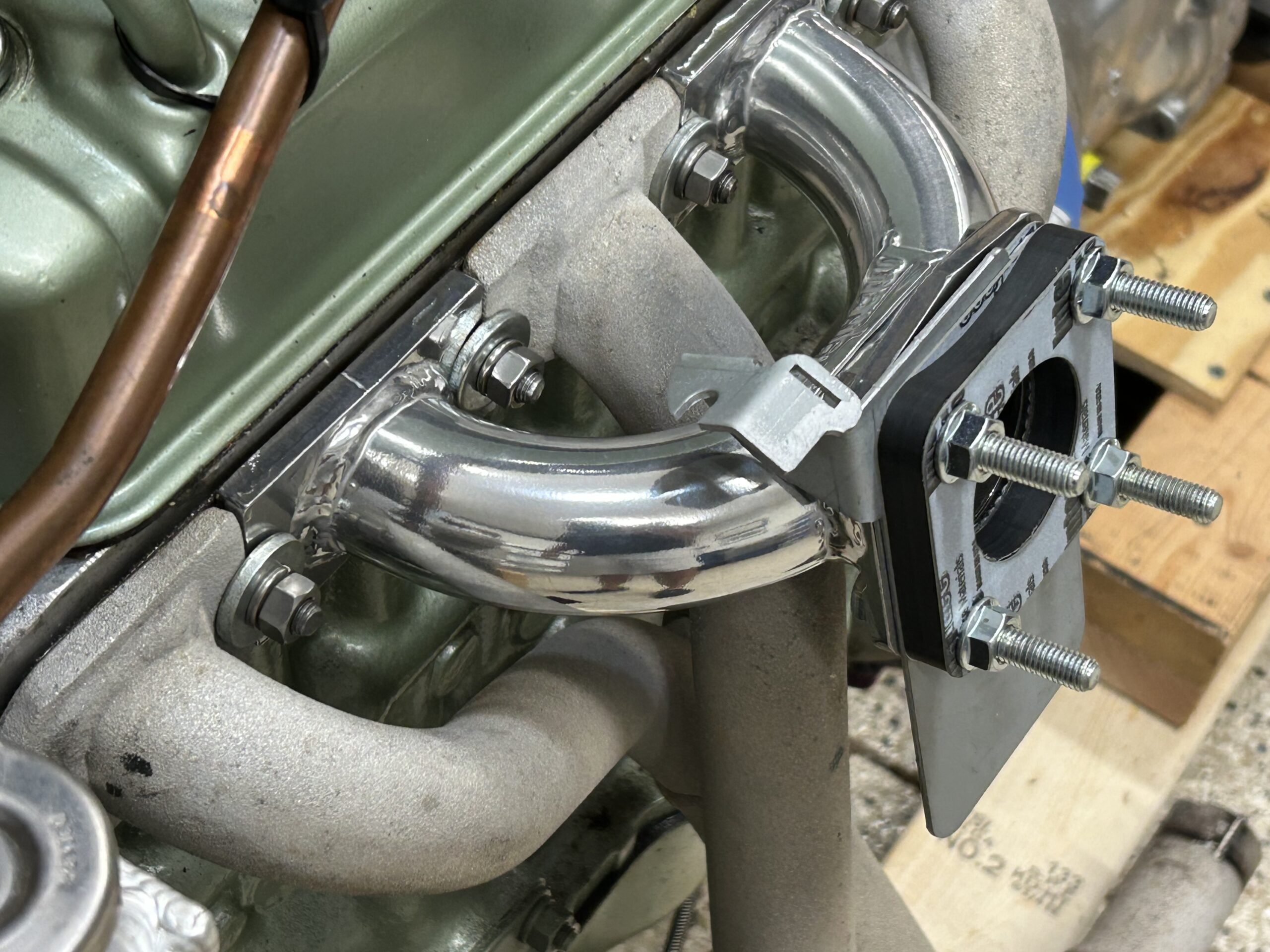
New Intake Assembly Mounted
After receiving the new HIF 44 carb from the UK it was installed and set up for initial running. The carburetor and its settings are detailed in another post under “personalizations.”
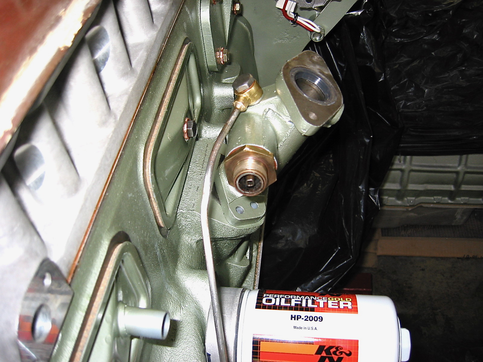
We then began preparations for actually starting the motor. The first step was to get oil into the engine and water into the radiator.