I really don’t recall when I last checked valve clearances, so as part of this ten year renewal process adjusting clearances was an obvious item for the checklist. You really don’t need many tools to take care of this project. An 8mm socket is used to loosen the hose clamps on the crankcase breather apparatus, a 1″ open end wrench is used to loosen and remove the two rocker cover cap nuts with cup washers and rubber bushes, a medium-size flat screw driver is used to turn the rocker adjusting screws, a 9/16″ box wrench is used to loosen and tighten the adjusting screw nuts, a feeler gauge is used to adjust the gap between the adjusting screws and rocker arms and finally, a spark plug socket and ratchet is used to remove the spark plugs.
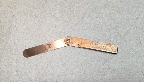
I purchased my feeler gauge at the same time I acquired the Healey in 1971. It is still in my tool bag after all of these years:
The workshop manual call for a clearance of .012″ or .3mm between the adjusting screws and the rocker arms for both inlet and exhaust valves. There are lots of good resources on the web and on Youtube that describe the process.
I loosened the breather hose clamps and moved the hoses and clamps out of the way so that the rocker cover can be removed.
I then cleaned the base of the rocker cover to make sure no debris would fall into the cylinder head when the cover is removed.
I then loosened and removed the cap nuts, washers and rubber bushes from the rocker cover and carefully lifted the cover off the engine, taking care to keep the silicone gasket in place so that it could be used again. The cover was then cleaned and set aside. I also carefully cleaned the surface of the head where it mates with the cover.
Next, was the removal of the spark plugs. This is done to make it easier to roll the car when needed for the valve adjustment process. This is also a good time to inspect and clean the plugs. Mine are visually new so not much was required. Care must be taken to ensure that the plug cables are numbered so that they are reconnected in the proper sequence!
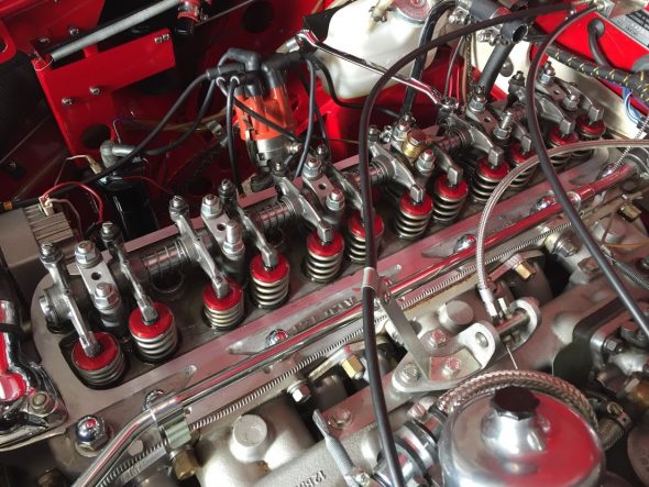
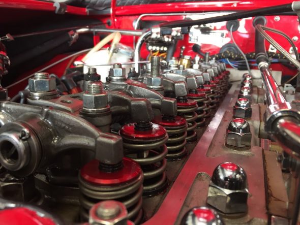
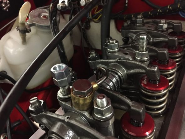
I guess I should bathe in motor oil each morning because it sure makes for good preservation of surfaces. The images below show the Dennis Welch head assembly after almost ten years on the car!
Checked the clearances of each valve as I proceeded. Most were very close to spec although I had two that were a little tight.
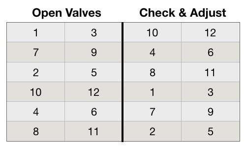
The “Rule of Thirteen” is used to know which valve to adjust on a 6 cylinder engine. If valve #1 is open (when the adjuster side of the rocker is up, and the spring side is down) then which valve do you adjust to get to a total of thirteen? The answer is valve #12. When valve #8 is open (up) then to get to a total of thirteen we need to adjust valve #5, and so on.
Valves open and close in pairs, therefore we can adjust the valves in pairs in accordance with the table below:
I backed my car into the garage – nose out – as far to the rear as possible and then let it sit over night so the engine would be completely cold.
The next day I put the car into 4th gear and pushed it forward and in my case the springs on rockers #1 and #3 began to depress. I continued to push the car forward until the springs were fully depressed so that the adjusting screws for valves #10 and #12 were ready to be checked and adjusted. You can either watch the spring movement carefully or you can put fingers on the rocker arms to sense the change in movement. Whichever method works for you is fine. Some people push the front tire to move the car while in gear, others use a wrench on the crank nut or on the alternator/generator pulley nut, or just pull on a fan blade in a clockwise motion (be careful).
Once the adjuster screw is identified that I wanted to adjust (in this case #10), I loosened the adjuster nut, placed my .012″ feeler blade between the rocker and the valve stem and tightened the adjuster nut until the feeler blade was snug and while carefully holding the screwdriver on the adjusting screw so that it would not move (a little tricky) I tightened the nut tightly. I then checked the feeler gauge and readjusted if it was too tight or too loose. This process takes a little practice, but you get the hang of it pretty quickly.
I then moved on to the #12 valve and completed the same process.
I then slowly pushed the car forward again until the valve springs for #7 and #9 were fully depressed. I then adjusted valves #4 and #6.
I continued with the progression shown in the table above until all valve clearances were properly adjusted.
Next the car was put in neutral and pushed to the rear of the garage again. Then I repeated the full process checking the clearances of each valve a second time. In this case double-checking is certainly a good thing and worthwhile!
Valve adjustment was then complete.
Sealing The Rocker Pedestal Studs
Fellow Healey owner Steve Gerow pointed out that one needs to be sure to apply sealant to the rocker pedestal studs otherwise oil can seep through the studs and leak into the cavity in which the park plugs are located. I noticed that on my car I was getting a little oil into two of the spark plug cavities, so, after adjusting the valves and before replacing the spark plugs and rocker cover I decided to pull the rocker studs and apply some high temperature sealant to the threads.
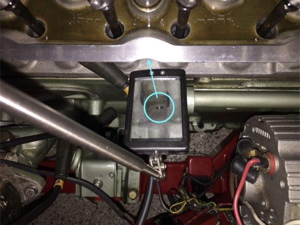
If one uses a mirror you can see where these rocker stud holes are drilled all the way through the head. If not properly sealed one can see that a leak could easily develop.
To remove the studs I used the double-nut procedure where one screws a second nut onto the stud and tightens it against the existing nut. A wrench can then be used on the lower nut to slowly turn the stud out of its home.
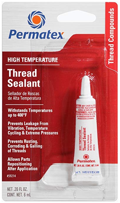
Following Steve’s suggestion I cleaned the stud and cylinder head threads with brake cleaner and then blew them dry with compressed air. I applied Permatex high temperature thread sealant to the threads per the instructions.
The last step was to torque the rocker pedestal stud nuts to 25 ft. lbs. Another job complete.

