Valve Adjustment

I really don’t recall when I last checked valve clearances, so as part of this ten year renewal process adjusting clearances was an obvious item for the checklist. You really don’t need many tools to take care of this project. An 8mm socket is used to loosen the hose clamps on the crankcase breather apparatus, a 1″ open end wrench is used to loosen and remove the two rocker cover cap nuts with cup washers and rubber bushes, a medium-size flat screw driver is used to turn the rocker adjusting screws, a 9/16″ box wrench is used to loosen and tighten the adjusting screw nuts, a feeler gauge is used to adjust the gap between the adjusting screws and rocker arms and finally, a spark plug socket and ratchet is used to remove the spark plugs.

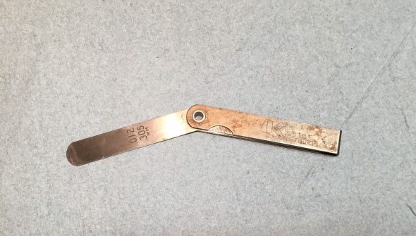
I purchased my feeler gauge at the same time I acquired the Healey in 1971. It is still in my tool bag after all of these years:

Forty-seven year old feeler gauge

The workshop manual call for a clearance of .012″ or .3mm between the adjusting screws and the rocker arms for both inlet and exhaust valves. There are lots of good resources on the web and on Youtube that describe the process.

I loosened the breather hose clamps and moved the hoses and clamps out of the way so that the rocker cover can be removed.

I then cleaned the base of the rocker cover to make sure no debris would fall into the cylinder head when the cover is removed.

I then loosened and removed the cap nuts, washers and rubber bushes from the rocker cover and carefully lifted the cover off the engine, taking care to keep the silicone gasket in place so that it could be used again. The cover was then cleaned and set aside. I also carefully cleaned the surface of the head where it mates with the cover. 

Next, was the removal of the spark plugs. This is done to make it easier to roll the car when needed for the valve adjustment process. This is also a good time to inspect and clean the plugs. Mine are visually new so not much was required. Care must be taken to ensure that the plug cables are numbered so that they are reconnected in the proper sequence!

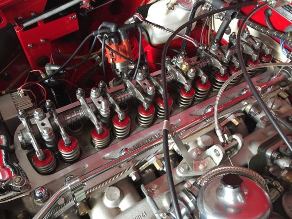
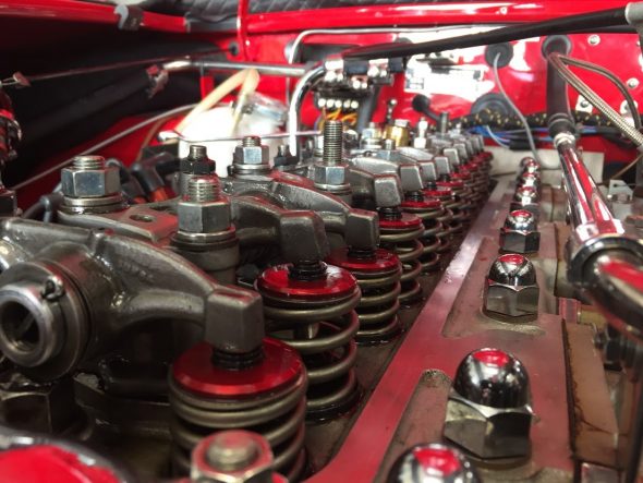
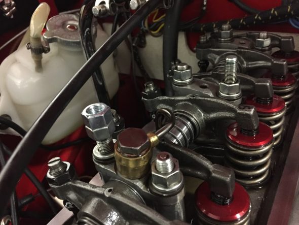
I guess I should bathe in motor oil each morning because it sure makes for good preservation of surfaces. The images below show the Dennis Welch head assembly after almost ten years on the car!

Rocker Arm Assembly

Rocker Arm Assembly

Checked the clearances of each valve as I proceeded. Most were very close to spec although I had two that were a little tight.

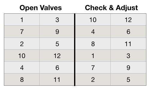
The “Rule of Thirteen” is used to know which valve to adjust on a 6 cylinder engine. If valve #1 is open (when the adjuster side of the rocker is up, and the spring side is down) then which valve do you adjust to get to a total of thirteen? The answer is valve #12. When valve #8 is open (up) then to get to a total of thirteen we need to adjust valve #5, and so on. 

Valves open and close in pairs, therefore we can adjust the valves in pairs in accordance with the table below:

Valve Adjustment Table

I backed my car into the garage – nose out – as far to the rear as possible and then let it sit over night so the engine would be completely cold.

The next day I put the car into 4th gear and pushed it forward and in my case the springs on rockers #1 and #3 began to depress. I continued to push the car forward until the springs were fully depressed so that the adjusting screws for valves #10 and #12 were ready to be checked and adjusted. You can either watch the spring movement carefully or you can put fingers on the rocker arms to sense the change in movement. Whichever method works for you is fine. Some people push the front tire to move the car while in gear, others use a wrench on the crank nut or on the alternator/generator pulley nut, or just pull on a fan blade in a clockwise motion (be careful).

Once the adjuster screw is identified that I wanted to adjust (in this case #10), I loosened the adjuster nut, placed my .012″ feeler blade between the rocker and the valve stem and tightened the adjuster nut until the feeler blade was snug and while carefully holding the screwdriver on the adjusting screw so that it would not move (a little tricky) I tightened the nut tightly. I then checked the feeler gauge and readjusted if it was too tight or too loose. This process takes a little practice, but you get the hang of it pretty quickly.

I then moved on to the #12 valve and completed the same process. 

I then slowly pushed the car forward again until the valve springs for #7 and #9 were fully depressed. I then adjusted valves #4 and #6.

I continued with the progression shown in the table above until all valve clearances were properly adjusted.

Next the car was put in neutral and pushed to the rear of the garage again. Then I repeated the full process checking the clearances of each valve a second time. In this case double-checking is certainly a good thing and worthwhile!

Valve adjustment was then complete. 

Sealing The Rocker Pedestal Studs

Fellow Healey owner Steve Gerow pointed out that one needs to be sure to apply sealant to the rocker pedestal studs otherwise oil can seep through the studs and leak into the cavity in which the park plugs are located. I noticed that on my car I was getting a little oil into two of the spark plug cavities, so, after adjusting the valves and before replacing the spark plugs and rocker cover I decided to pull the rocker studs and apply some high temperature sealant to the threads.

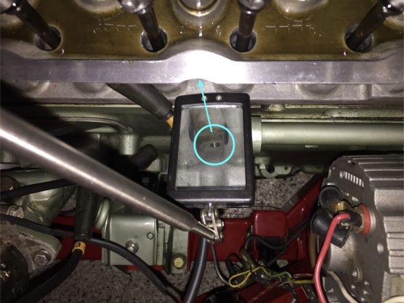
If one uses a mirror you can see where these rocker stud holes are drilled all the way through the head. If not properly sealed one can see that a leak could easily develop.

Rocker Pedestal Stud Hole in Spark Plug Cavity

To remove the studs I used the double-nut procedure where one screws a second nut onto the stud and tightens it against the existing nut. A wrench can then be used on the lower nut to slowly turn the stud out of its home.

Double-nuttting studs

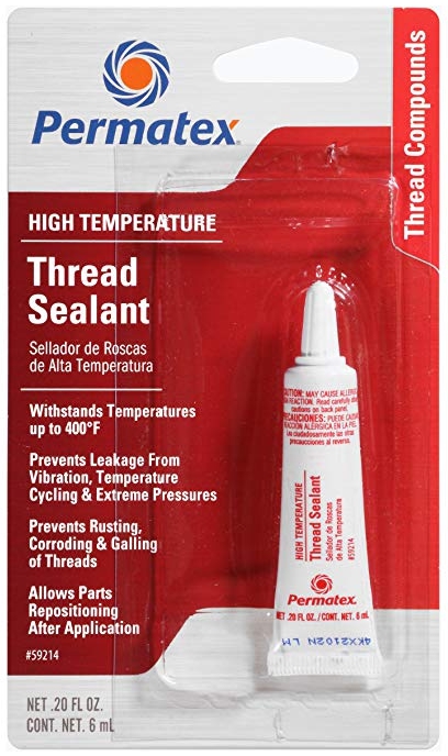
Following Steve’s suggestion I cleaned the stud and cylinder head threads with brake cleaner and then blew them dry with compressed air. I applied Permatex high temperature thread sealant to the threads per the instructions. 

Permatex High Temperature Thread Sealant

The last step was to torque the rocker pedestal stud nuts to 25 ft. lbs. Another job complete.

Chapter 74 Week Forty-Four October 15, 2007

With the engine in place, it was now time to complete the assembly of the various engine components, but first I installed the clutch slave cylinder with the push rod provided in the Smitty conversion kit. It went in without any problem and lined up perfectly. The clutch pedal seemed to work smoothly. The bleeder extension pipe was attached to the bracket I made to support the pipe. Bleeding the slave cylinder will now be a much easier job. Thanks again to Mr. Finespanner – Doug Reid.

Slave cylinder bleeder extension 2

Just to fill the holes and to prevent anything from dropping in unexpectedly I went ahead and loosely fit the NGK Spark Plugs BP6ES, stock number 7333.

To make installation a little easier I attached the gear reduction starter to the engine prior to installation in the car, and it was now time to hook up the wiring. I shortened the heavy duty starter cable that connects the solenoid and the starter and secured it to the starter with rubber insulation boots attached. Since my intention is to still rely on the original starting configuration, that is, using the external solenoid, I connected the small wire on the starter to the terminal post also used to connect the cable from the solenoid.

Starter

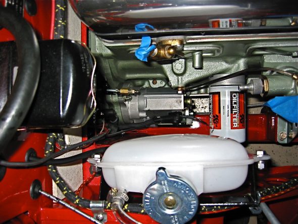
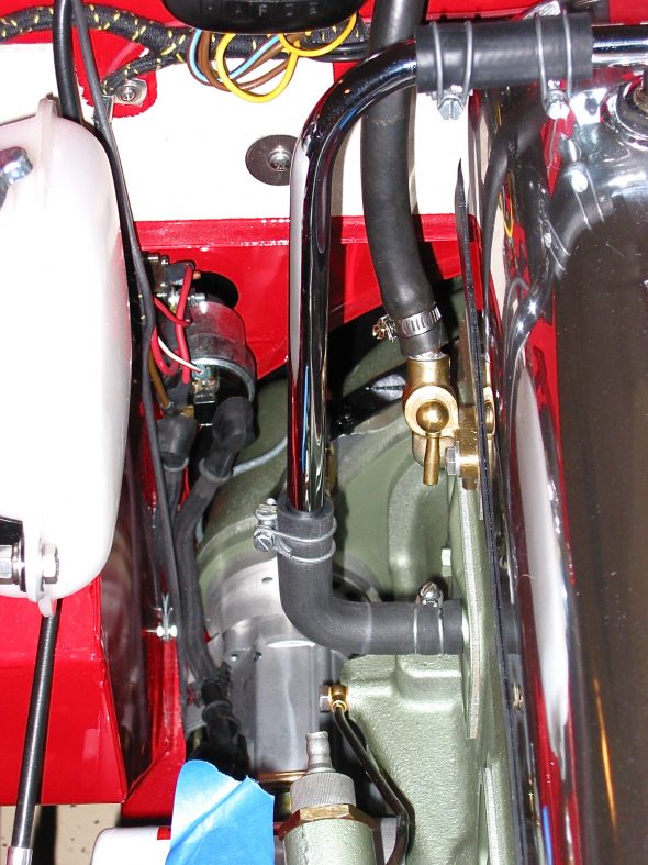
The installation of the breather pipe and hoses was next on my list. Since I will be taking off the rocker cover for valve gap adjustment once the engine is started, I left the clamp to the “T” connection on the cover loose. The inlet heater hose from the heater to the heater control tap on the motor. While in that location I went ahead and connected the tachometer cable to the tach drive housing.

Breather Pipe 2

Tach Cable to Drive Gear

Others have suggested the addition of a PCV valve connecting the breather “T” to the intake manifold to assist in minimizing oil pressure leaks. I bought a little kit from the British Car Specialists that included the valve, rubber piping and a connector for the intake manifold. It will be interesting to see if it does aid in respiration.

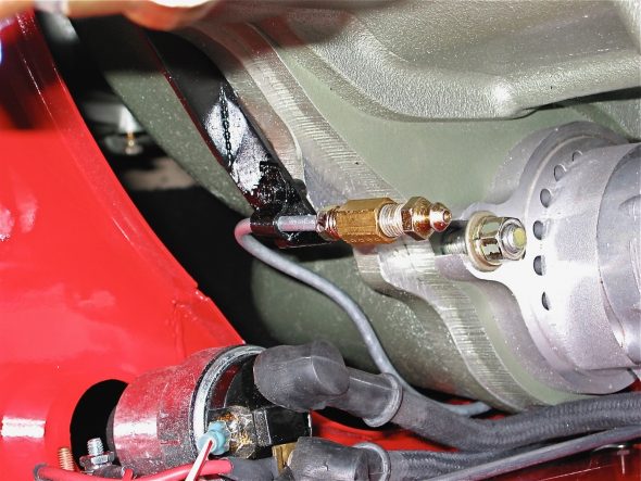
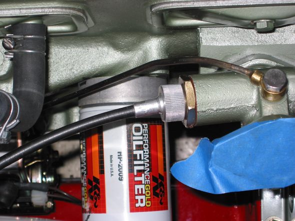
The oil gauge flexible hose was connected next. It connects to a fitting on the block and to the steel oil line that connects to the back of the oil pressure/water temperature gauge.

Oil Pressure Line


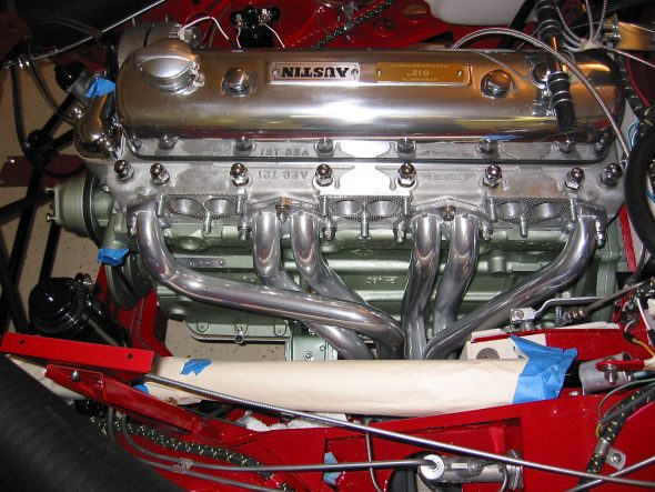
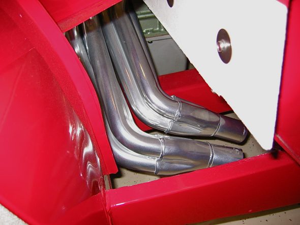
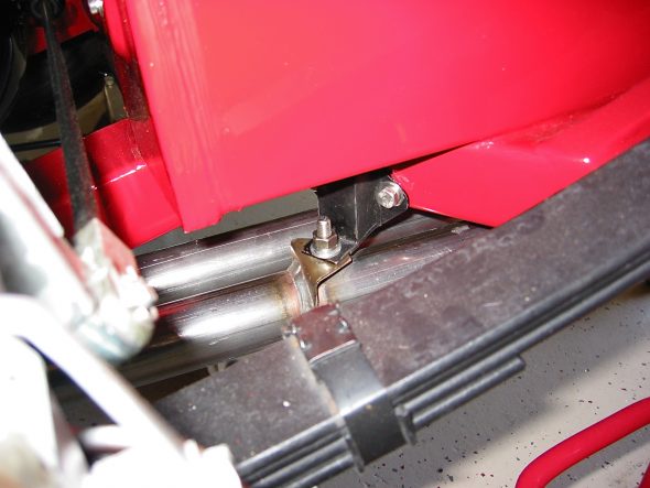
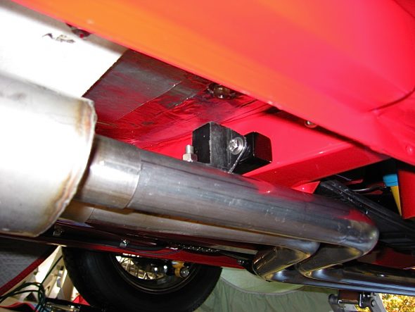
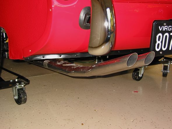
The exhaust headers were next to be installed. These are Phoenix headers and the full big bore exhaust system was sourced from AH Spares. The headers fit perfectly without any adjustments. I had them Jet-Hot coated in the sterling finish to keep them looking nice and to improve thermal qualities. Stainless steel flexible pipe (1 7/8”) was used to connect the headers to the stainless steel silencer and the big bore tail pipes. The front hanger bracket is in the wrong place for a BT7, so I made a custom spacer for that hanger. The rear hanger worked just fine. I was pleased with the final installation of the system.

Headers 1

Headers 3

Rear Hanger 2

Middle Hanger


Tail Pipes 2

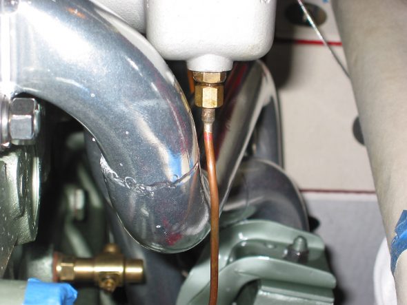
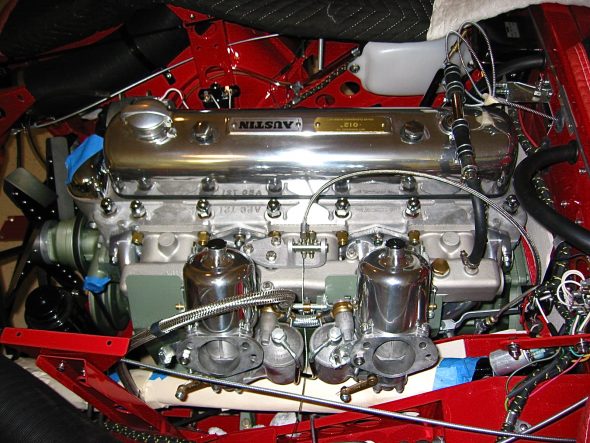
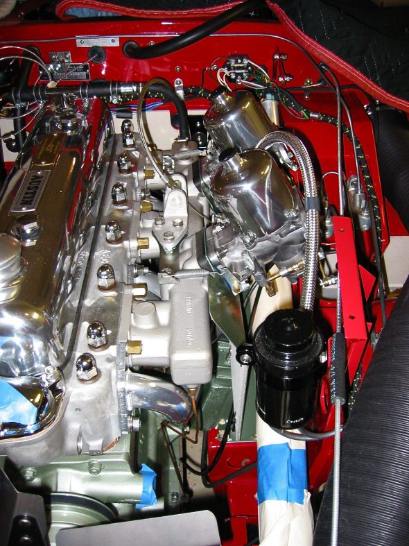
I assembled the intake manifold, heat shield and carbs to the Bloody Beast. Those lower mounting nuts are not easy to access! The stainless steel flexible fuel lines were connected to the steel fuel line and to the two SUs. I had to pull everything off the engine when I realized that I had not yet attached the manifold fuel drain pipes!! As it turned out they are very close to the header pipes, but after checking with a few people who are more informed about such matters than me, I think I am comfortable leaving them as they are. They should have been installed along with the vacuum line BEFORE the rest of the engine components!!!!

Front fuel drain line

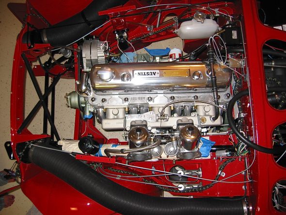
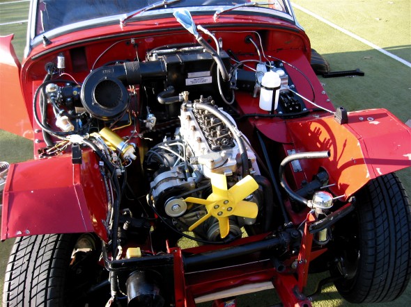
Engine from above

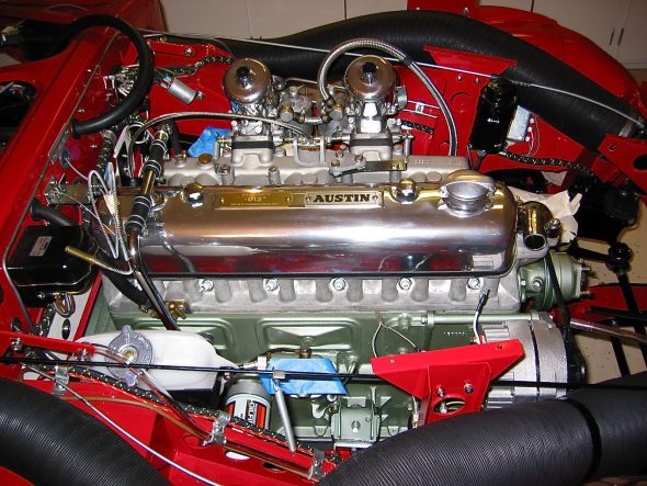
Engine from right

Engine LH view

Engine front view

Chapter 6 – Disassembly

Rocker Cover – loosened two bolts and removed rocker cover.

Rocker Cover removal

July 3, 2002

Engine Removal, cont’d

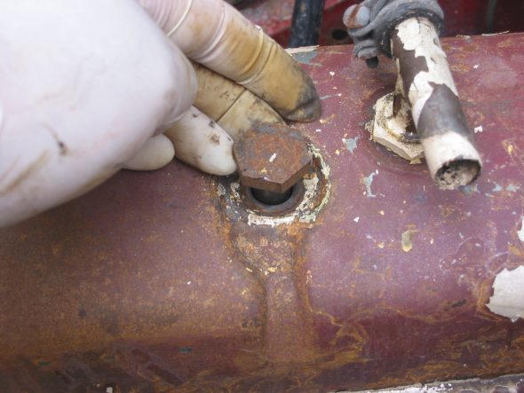
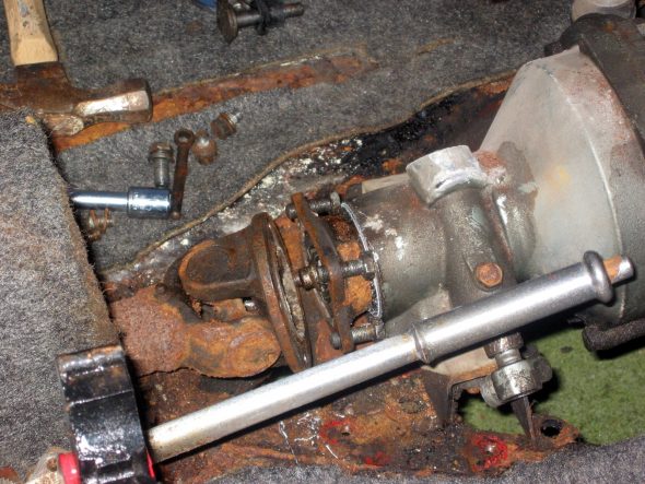
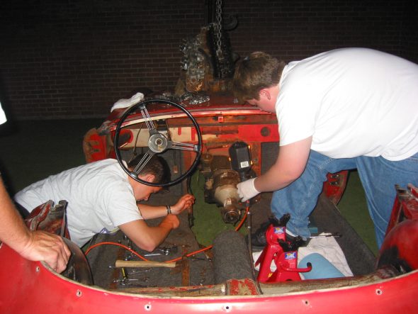
Gearbox mounts –  Removed 4 bolts securing the gearbox mounts and 4 bolts and nuts from the Propshaft at the gearbox union. The bolts on the gearbox side cannot be removed without removing shaft nut. There were also 2 nuts of the same size to remove on the underside of the chassis. Finally, the nut and securing pin on the gearbox stabilizer must be loosened and removed to free the gearbox.

Propshaft Removal

Clutch slave cylinder – Detached the cylinder from the bell housing by removing 2 bolts. Must also release the clutch operating lever by removing the cotter pin from the clevis pin.

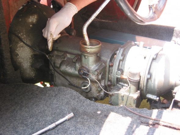
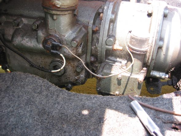
Disconnected the wire clamp on the bell housing and unclipped the wire to the gearbox switch for the overdrive.

Overdrive Wiring Clip

Overdrive Wiring

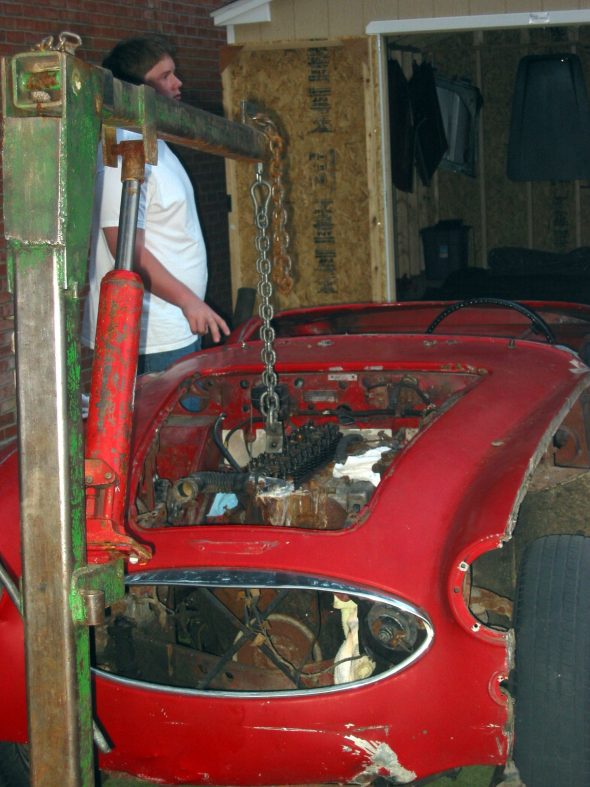
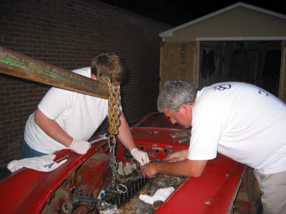
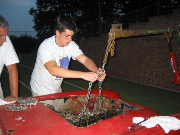
Engine Hoist – We then thought we were ready to connect the hoist and remove the engine and gearbox as one unit. If we were doing this again, we would have waited until the shroud was removed to avoid any damage. It would have also made it easier to swing out the entire unit had we jacked up the car a bit first. That would have given the gearbox more room to swing vertically. Providing enough lift height on the hoist is a bit of a problem given the length of the combined engine and gearbox and the angle needed to successfully remove the unit. 

We also decided that while it isn’t theoretically necessary, it would be easier to pull the engine if the brake reservoir were removed. So we gave up due to darkness and gently reset the engine in the bay.

Helper Scott

Securing the Hoist Chain

Helper John

Freeing the Gearbox

Progress!

Resting for the Night!

July 4, 2000

Engine Removal, cont’d

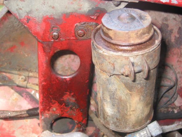
Brake fluid reservoir – Removed the container by loosening one nut securing the bracket, and then loosening the two brass brake line nuts to the container. Note that there are also nuts on the bottom of the canister.

Brake/Clutch Fluid Reservoir

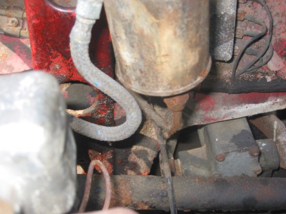
Brake/Clutch Fluid Pipes to Reservoir

Hydraulic lines –  Removed the hydraulic lines from the master cylinders to the reservoir canister. Note double clasp or clip on fender secured by a nut and bolt on outside of fender well. The longest pipe is the brake and is connected closest to the front of the car. Shorter pipe is the clutch line.

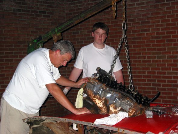
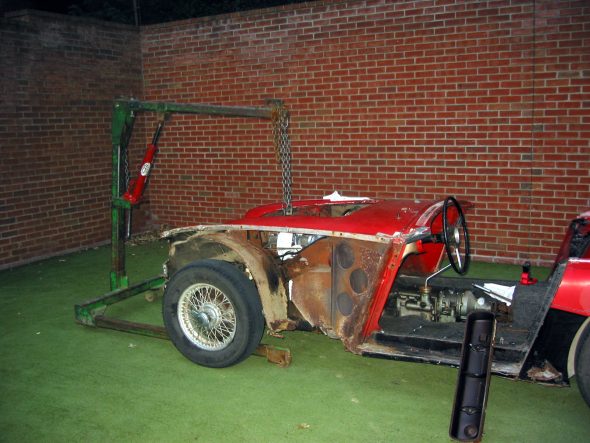
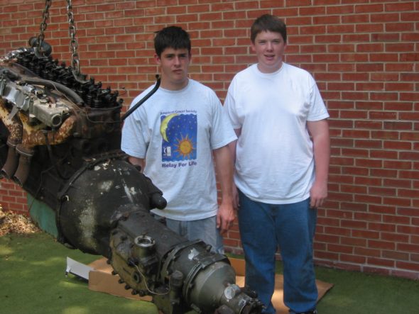
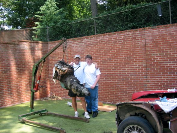
Attempted to remove the engine with the lift again. This time with better light, a less crowded space and with the lift chain adjusted we easily removed the engine and transmission.

The Helpers Got it Done!

Lin, Scott and the Beast

Free at Last with Gearbox Removed


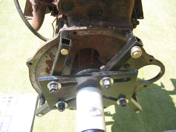
Clutch Assembly and Ready For the Engine Stand

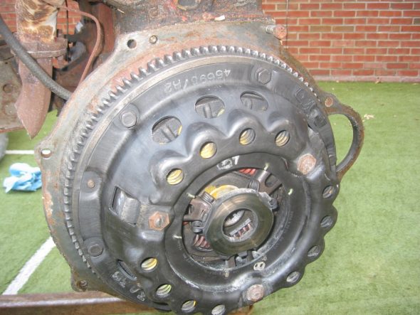
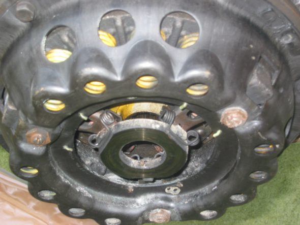
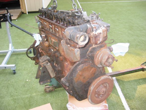
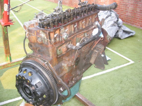
To mount the engine on the stand it was necessary to remove the gearbox from the engine. The bell housing was secured with 9  3/8” x 24 bolts including two that mount the starter. The bolt on the top right secures to the engine block without a nut. All other bolts have nuts. After removing the transmission we then had to remove the clutch. You must gradually slacken the cover screws a turn at a time until the spring pressure is relieved.

Clutch Assembly 1

Clutch Assembly 2

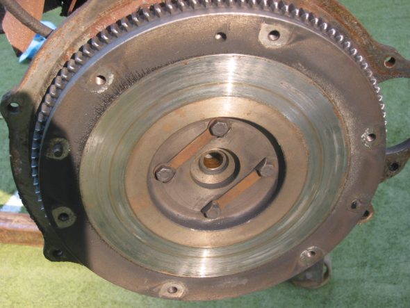
After the clutch assembly was removed, the flywheel was exposed. Four nuts with the lock washer straps were loosened. The crankshaft pulley must be held on the front of the engine to prevent the shaft from turning.

Exposed Flywheel

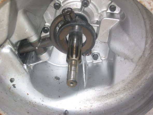
Clutch Fork

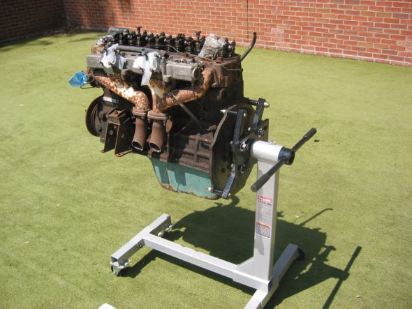
We were then able to transfer the engine from the lift to the engine stand.

On the Engine Stand

Engine Stand Mounting

July 22, 2002

Wings

The Front Wing – Removed 3 bolts joining the front shroud and the front wing below the headlight. These are slightly shorter than those used to secure the top of the shroud and the wing together. They are tightened to spring-clip type nuts. Removed the headlight and sidelight. The sidelight is fastened with three small screws and nuts on the reverse side. Two pieces of plastic piping are found above and below the sidelight. Four brass nuts accessible beneath the wing hold the headlight bucket in place. Seven bolts fastened the shroud to the wing along the top edge. Three bolts and nuts secure the wing to the frame along the bottom edge. Seven small self tapping screws fasten the wing in the door jamb to the hinge pillar.

The Rear Wing – Removed three bolts inside the interior and three inside the boot to remove the rear wing. The bolt located closest to the rear of the car, but still in the interior has a regular nut rather than a clip spring nut which must be held with a wrench when removing. There is also a screw near the door under the aluminum trim that fastened into a steel plate. At the bottom of the rear wing there are two bolts and nuts securing the wing to the frame and a vertical drive sheet metal screw. Finally, eight cross-head screws with nuts fix the wing to the door shut pillar and they must be removed.
 

Engine Clean-up and Reinstall

Engine Install

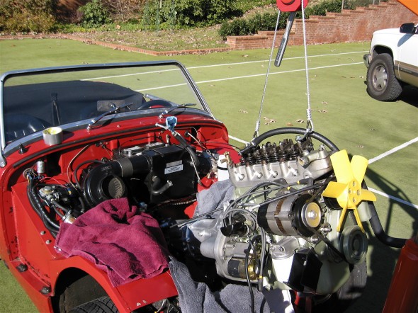
Engine Install

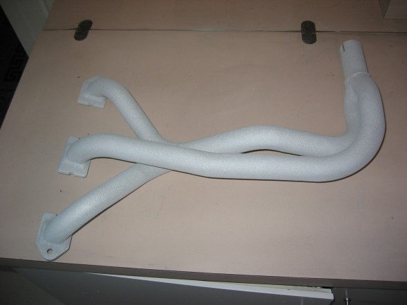
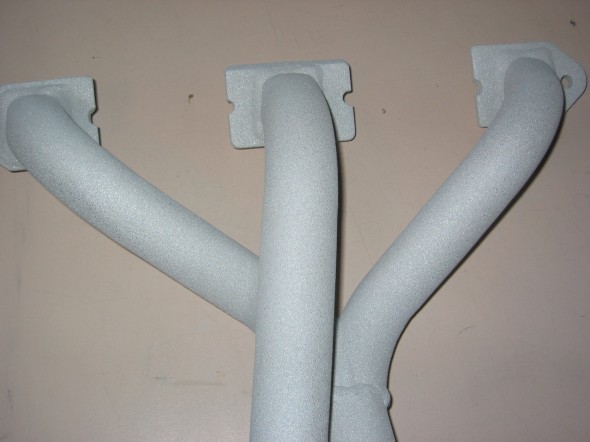
One of the things I wanted to accomplish with the engine clean-up was to have the  exhaust header coated to reduce heat in the engine compartment and interior. I used Swain Coatings. The header came back looking great. Time will tell if the coating holds up and is effective in reducing heat.

Swain Coat Header

Swain Coat Header

Swain Coat Header

Swain Coat Header

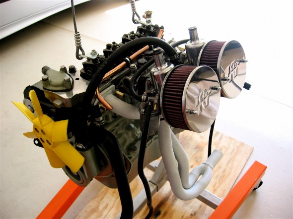
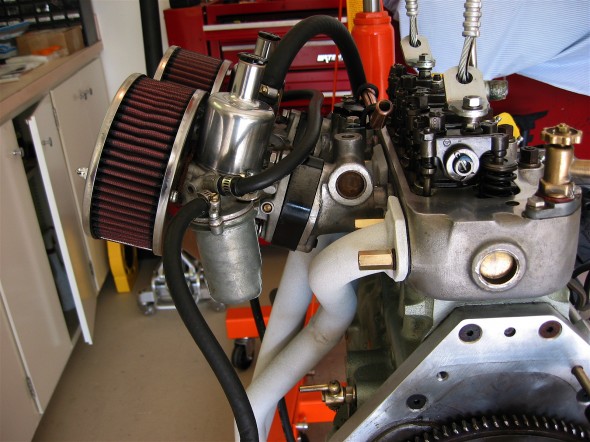
I also did a general cleaning of the engine including a new paint job while the gearbox was being worked on by Jack Harper. I replaced the oil sump gasket and the rocker cover gasket, too. I tested and reinstalled the gear reduction starter. The air cleaners were cleaned and oiled with K&N products.

Clean Motor Assembly

Clean Motor Assembly

Clean Motor Assembly

Clean Motor Assembly

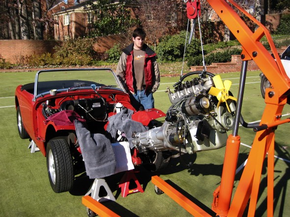
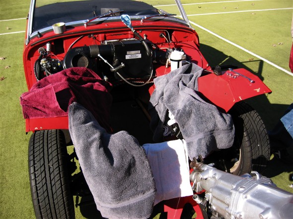
I developed the following list of items for reinstalling the engine and gearbox into the Bugeye:

Reinstalling a Bugeye Engine and Datsun 5-speed Transmission

  1. Grease the shaft splines on the engine and the yoke before installing the engine.
  2. Set the exhaust header in place so that it will be positioned to install once the engine is tightened into its mounts.
  3. Guide the motor into place with the lift so that the yoke on the driveshaft lines up with the transmission. If this does not work then remove the driveshaft and install after the engine and transmission are in place.
  4. Loosely secure the engine to the front motor mounts. The mounts themselves should be loose then tightened after all bolts/nuts are in place.
  5. Install the long bolts up through the crossmember into the rear transmission mount and tighten.
  6. Tighten the front engine mounts.
  7. Center the transmission in the rear mount, then push it as far to the right as possible, and tighten the transmission pad mounts on the bracket.
  8. Install the bolts in the sides of the transmission rear mounts from inside the car with the self locking nuts inside the tunnel. (Hint: tape the nuts in the wrench to make starting the threads easier.)
  9. Replace the gearshift lever.
  10. Connect the ground strap to the frame of the car.
  11. Replace the rocker cover and connect the breather hose.
  12. Install the intake and exhaust manifolds.
  13. Install heat shield and carbs.
  14. Connect throttle and choke cables.
  15. Connect breather hose.
  16. Connect hot water hose to copper tube and connect to radiator hose. Tighten clamps. It is easier to put the clamp on the hose/copper pipe when the copper pipe clips are loose from the manifold.
  17. Connect the short hot water hose from the water control valve to the heater.
  18. Connect the electrical cable from the gear reduction starter to the starter solenoid.
  19. Connect the oil pressure pipe to the fitting on the engine block by the banjo bolt.
  20. Reconnect the white/black line from the electronic ignition to the distributor.
  21. Connect the high tension line from the distributor to the coil.
  22. Reconnect the plastic terminal (3 wires) to the alternator.
  23. Connect the fuel line from the fuel pump to the carbs.
  24. Reattach the water temperature sensor to the engine head.
  25. Remove the banjo bolt where the oil line exits the rear of the block. Pour motor oil down the hole in the block to prime the oil pump. Reinstall the bolt.
  26. Remove the oil filter and pour it full of motor oil and reinstall.
  27. Fill engine with oil – Castrol GTX 10W-40.
  28. Fill the gearbox with Gear lube – Redline MT90. 2 1/4 pints. Use long clear plastic tube. Try pump.
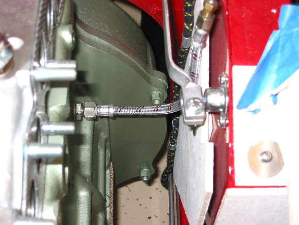
  29. Connect the stainless steel flex line from the master cylinder to the slave cylinder.
  30. Bleed the clutch slave cylinder. (See Page 9 of Rivergate’s manual)
  31. Install radiator and fill with 50% coolant and 50% distilled water.
  32. Fix the carb drain lines to the mounting clamp at the lower rear of the engine compartment.
  33. Insert the 1 ½” connecter pipe (with sealant) for the exhaust system into the header pipe.
  34. Install the exhaust and muffler assembly.
  35. Tighten clamps on the exhaust connecter pipe.
  36. Reconnect the battery cables.
  37. When ready to start the engine, pull the spark plugs and spin the engine with the starter until the oil pressure goes up to normal on the pressure gauge, and stays.
  38. Check for any oil, coolant and fuel leaks.
  39. Reinstall the spark plugs and start engine.
  40. If engine does not start turn distributor 180 and try again!
  41. Install 4” fresh air heater hose and clamp.
  42. Install the leather shifter cover and surround.

Start It Up And Have Some Fun!

I Know It Fits!

I Know It Fits!

Motor Protection!

Motor Protection!


Engine Install

Engine Install