Throttle Cable Modification
The information below was originally posted in 2009 and modified in 2014. I have since updated how my throttle cable system works (2020) and information on the update is found in a post in my ten-year renewal blog. For example, I no longer us the Denis Welch intake manifold cable bracket. I decided to leave the entry below to provide the reader with history of the progression of this conversion process. This link will direct you to my latest post on the subject. https://valvechatter.com/?p=10123
Owning a Austin-Healey “Bugeye” Sprite always made me wonder about the somewhat arcane mechanical throttle linkage system in my BT7. The Bugeye has a very simple accelerator control system whereby the accelerator pedal and the carburetors are connected via a cable. This provides a direct and immediately responsive system assuming that the carburetor throttle shafts and components are in good condition. Having great respect for DMH and all that he did, I was hesitant to convert my Big Healey accelerator controls to a cable approach. I quizzed all of the Healey experts I could think of, and no one could give me a satisfactory explanation for the mechanical linkage. I suppose the most common response was “the linkage must have been around and used on other cars, so it was cheap to adopt.”
In 2005, my wife and I attended the Conclave held in Winston Salem, NC. There I saw John Trifari’s BN1 that had a throttle cable installation.
John Trifari Throttle Cable 1
John Trifari Throttle Cable 2
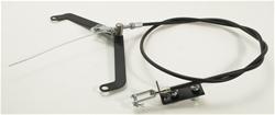
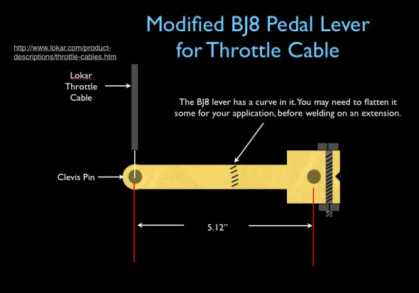
About that same time I was emailing back and forth with Jack Brashear a Healey owner from Arkansas who had also come up with a throttle cable approach to accelerator controls in his Healey. Jack did not modify anything at the accelerator pedal inside the interior, choosing instead to use a modified pedal shaft lever as shown in the image below. I will explain the lever modification a little later in this article. Both John and Jack used a little fitting that I believe came from an MGB through which the cable routes at the top of the driver’s footbox.
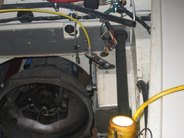
Jack Brashear Throttle Cable Install
Jack Brashear Throttle Cable Install
Also in 2005, I attended several of the races in the Australian/U.S. Healey Challenge series. Many of the Aussie’s cars had throttle cables instead of the mechanical linkage. Of course, the Australian cars are RH drive so the design is somewhat different (actually easier) than for LH drive cars. I noticed too that the Australian cars almost always incorporated some type of throttle stop mechanism. I suppose especially important in a race car.
Australian Racer with Throttle Cable and Throttle Stop
These examples and others that I came across about the same time convinced me that the use of a cable to control accelerator action to the carburetors was the approach that I wanted to take. However, everything that I had witnessed first hand was typically one-off, and custom designed, and I wondered if there was an easier route to my end game. I started checking vendors.
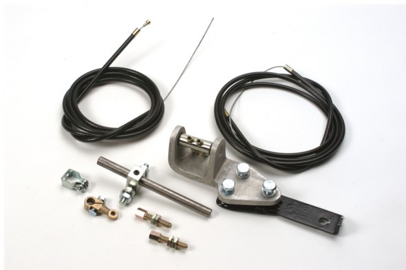
Cape International had a conversion kit http://www.cape-international.com/capeshop.php?parttypes=19&thepart=TC2# I actually tried this kit but wasn’t thrilled with it. I am sure it has been installed successfully in many cars, it just wasn’t my cup of tea.
Cape International Throttle Cable Kit
DMD from Australia also made a conversion kit. It is now available (as of August, 2014) from The Healey Factory. http://www.healeyfactory.com.au/dmd/components/ I did not personally try the DMD kit.
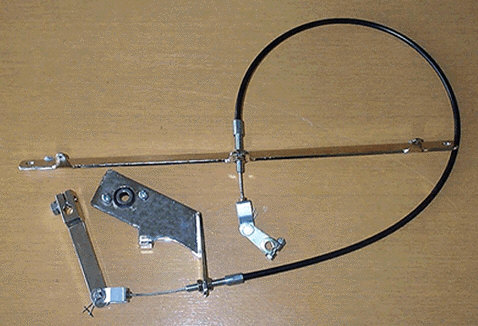
The Healey Factory DMD Throttle Cable Kit
I began to work on my own throttle cable kit using ideas I had seen on other cars or in the kits available from the vendors named. The narrative that follows chronicles my installation. It does not describe a right or wrong approach – it is just my approach. In fact, I am sure that others can improve upon my design. Comments and suggestions are certainly welcome.
Accelerator Pedal Swing Arm Lever
I decided to modify the throttle swing arm lever used on a BJ8 to suit my needs. I like this one better than the BT7 swing arm as it is a bit more substantial and in my view seemed a little less likely to slip on the pedal shaft once tightened. I have now used this arrangement since 2009 including an 8,000 mile cross-country trip without any problems. Jack Brashear suggested lengthening the arm so that it would swing perfectly in line with the firewall cable bracket and I followed his lead. I have headers on my car and a Toyota Supra Five-speed (not overdrive components on the firewall) so if the reader is planning a modification to the lever just make sure you have sufficient room. The following diagram illustrates the modification:
Throttle Swing Arm Lever Modification
Rose Throttle lever modified 1
Rose Throttle lever modified 2
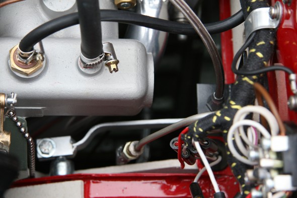
Firewall Bracket
I then made an “L” shaped bracket to mount to the firewall. I used the welded nut on the firewall (see above) for one of the securing points and drilled a hole for a nut cert for the top securing point. My final bracket looks slightly different than this one, but this is the best image I have to illustrate the mounting of the bracket to the firewall – note that it mounts through the firewall insulation panel.

Rose Firewall Throttle Bracket Version 1 – Not Final
The image below is not from my car but it shows a bracket similar to mine mounted on the firewall. I apologize that I do not know who owns this car. I just snapped the image at a show.
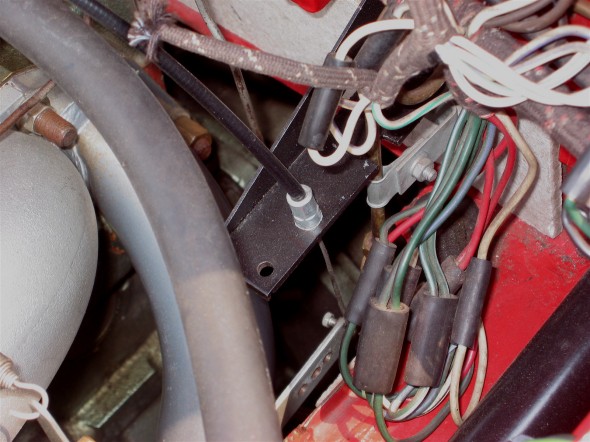
Firewall Throttle Cable Bracket – Unknown Owner
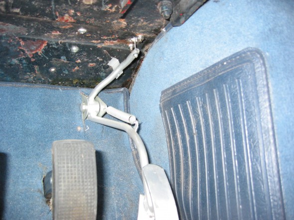
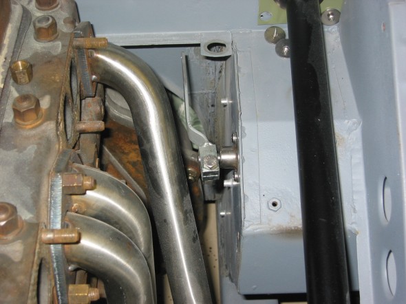
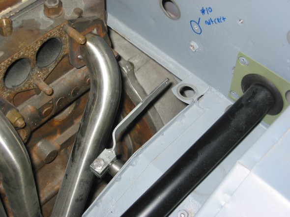
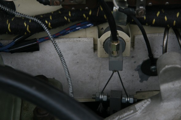
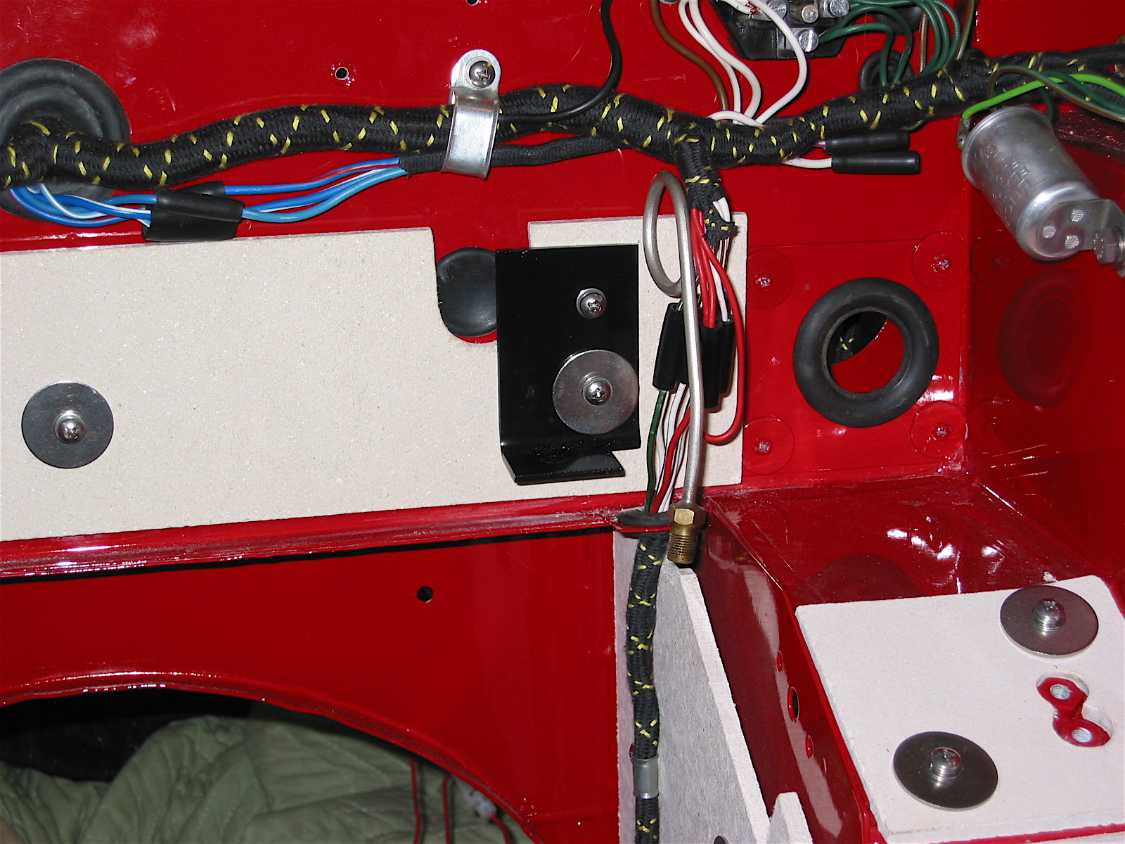
The following image is of my car and shows the relationship between the swing arm lever and the firewall bracket with the cable.
Relationship of Swing Arm Lever to Firewall Bracket and Cable
Carburator/Manifold Bracket
I tried numerous approaches to fabricating a bracket to get the cable to the right place to control the carburetor throttle shaft lever. You must decide if you want the cable to run down from the firewall, below the carbs, and up to the carburetor throttle shaft lever, or alternatively, do you want the cable to run up and over the carbs and manifolds? With my approach I chose to have it do the latter. It can be done either way.
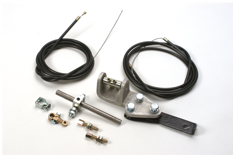
About the time I was trying to figure all of this out, Denis Welch came out with a LH drive throttle cable conversion kit that in my view is very well done. It contains a cast aluminum bracket that bolts to the intake manifold and runs a double cable from the pedal lever to the carburetor’s throttle shaft.
http://www.bighealey.co.uk/content/throttle-cable-conversion
Denis Welch Throttle Cable Kit
Because I had already begun my work and had my firewall bracket in place I decided to use the Welch cast aluminum bracket for my car, but not the rest of the kit. It has a swing mechanism built into to the cable housing that takes all alignment pressure off the cable. The kit is designed for racing cars and as such has a double cable. The double cable probably provides a somewhat smoother action and some security. I only use one cable, but I will probably switch to two at some point.
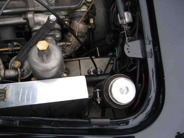
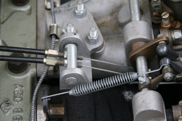
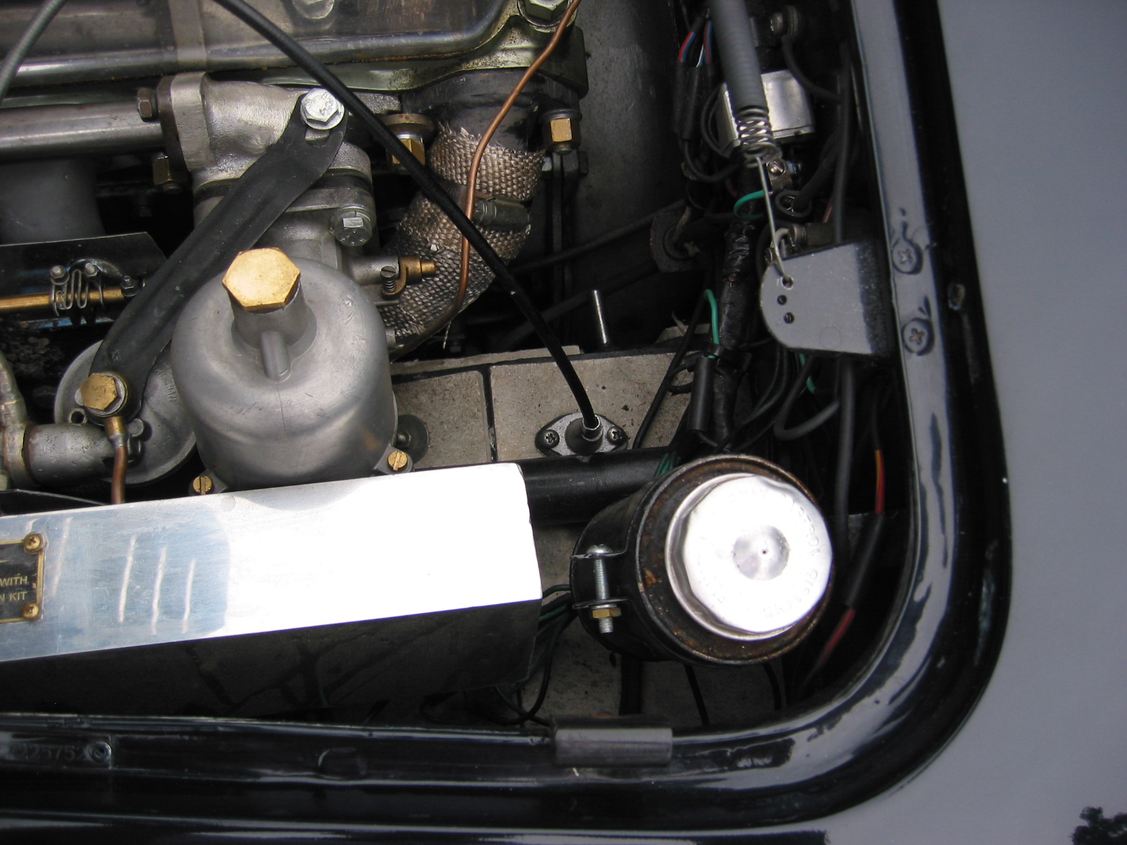
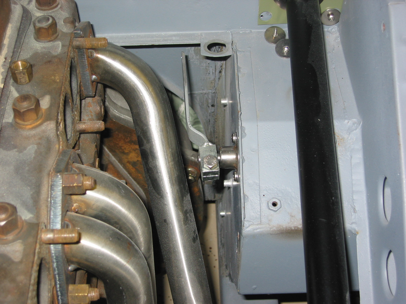
Approaching the carburetor throttle shaft lever from the manifold side of the carbs means you are pulling the carburetor throttle shaft lever up and there is not a great deal of room for that swing. I ended up cutting a notch out of my heat shield to remove any encumbrances. The image below shows the Denis Welch manifold-mounted bracket and the cut-out in the heat shield.
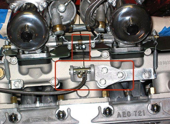
Welch Throttle Bracket
The Cable
The kits provide cable and fittings. I decided to use a Lokar cable and fittings only because I liked the braided cable appearance in the engine bay. Other’s may prefer black and in fact, Lokar now makes this same cable in black with black fittings. http://www.lokar.com/product-pgs/throttlecables-kickdowns/tc-kd-pgs/throttle-cables.html
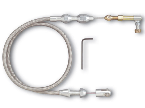
Lokar Throttle Cable
The Total Package
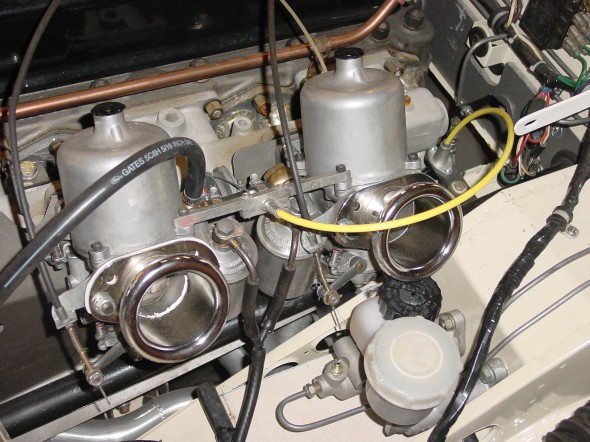
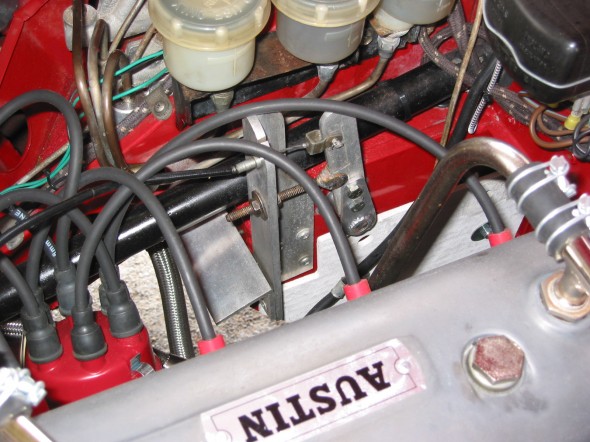
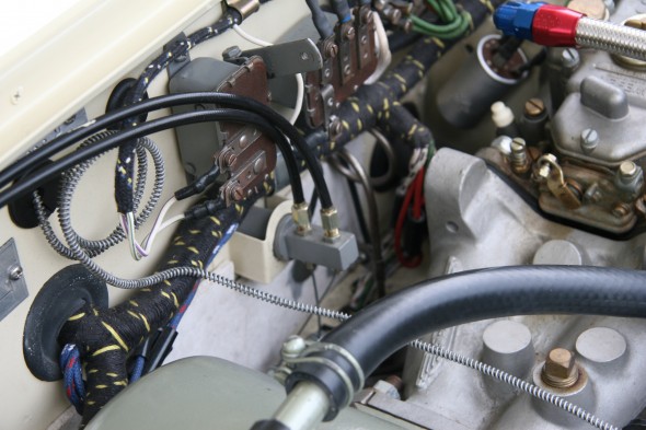
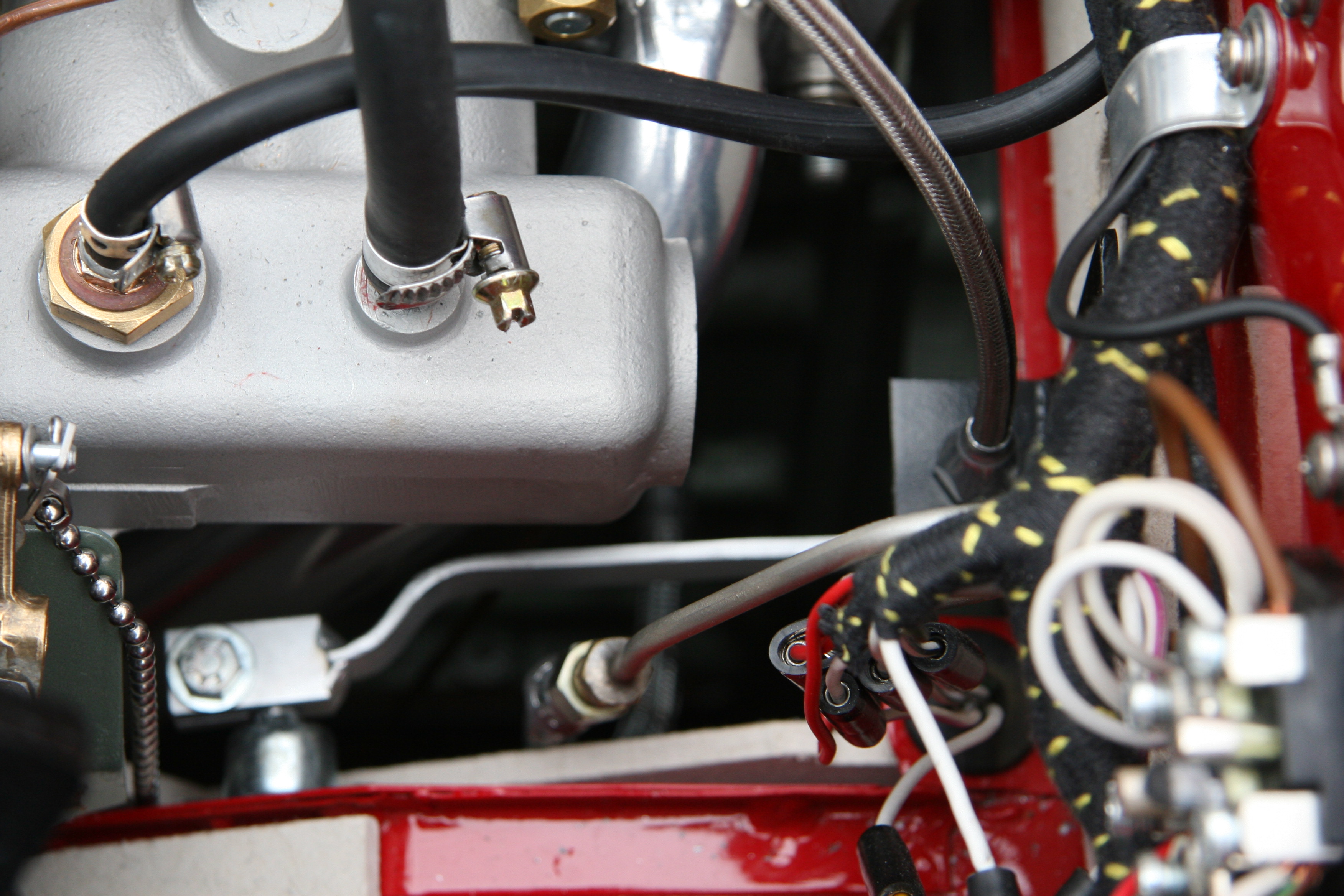
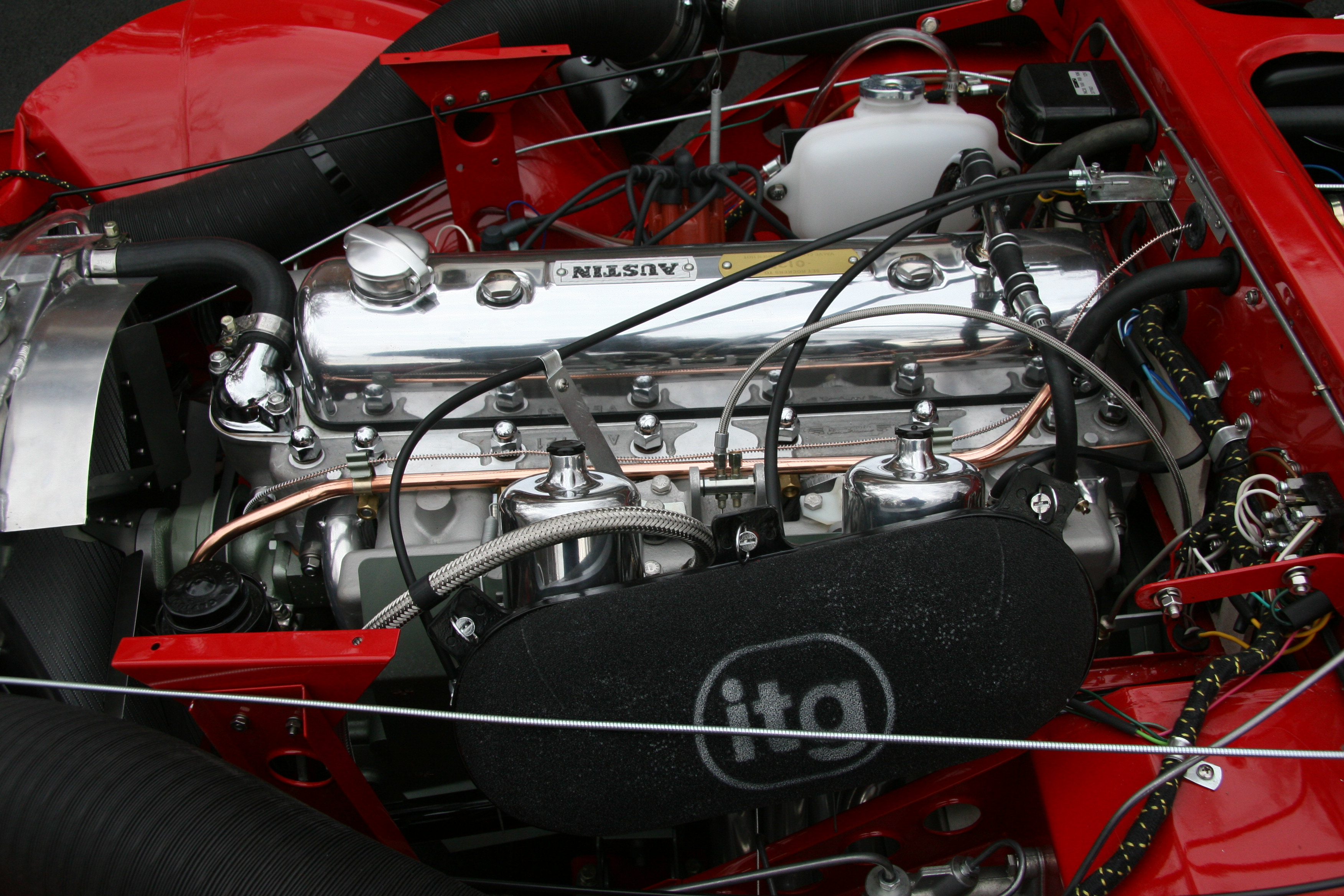
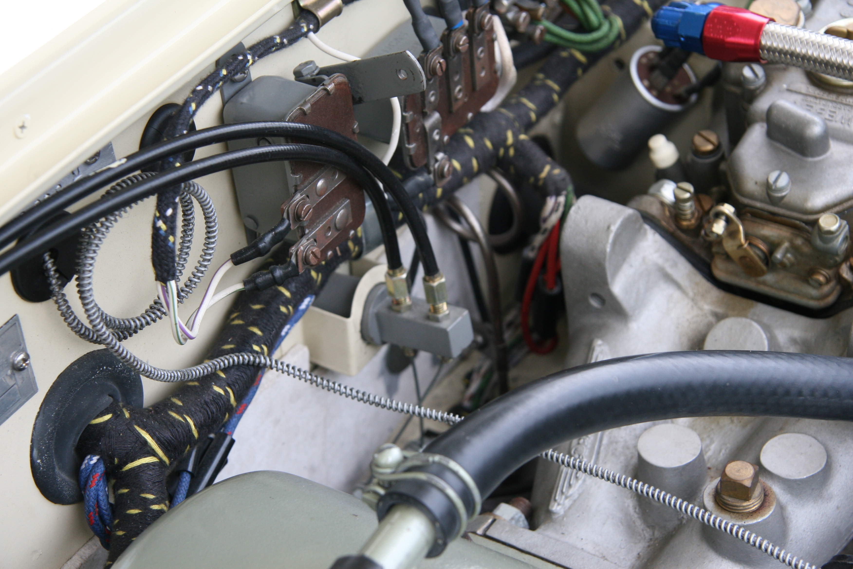
This image shows the engine bay with the throttle cable installed. I now run a stainless heater pipe rather than the copper, and my fuel hose routes differently on the front carburetor, but other than that things today are pretty much what you see in this image.
I cannot make meaningful comparisons between the functionality of the original throttle linkage and the new throttle cable. My mechanical linkage was fifty years old and worn out so comparisons are not appropriate. I do know that the cable has worked quite well, is very responsive, and much easier to get to than the original mechanical system.
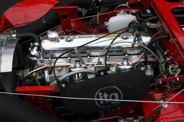
My Bloody Beast Engine with Throttle Cable
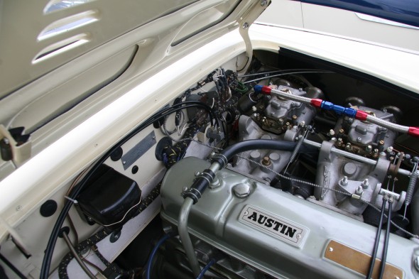
Another’s Installation
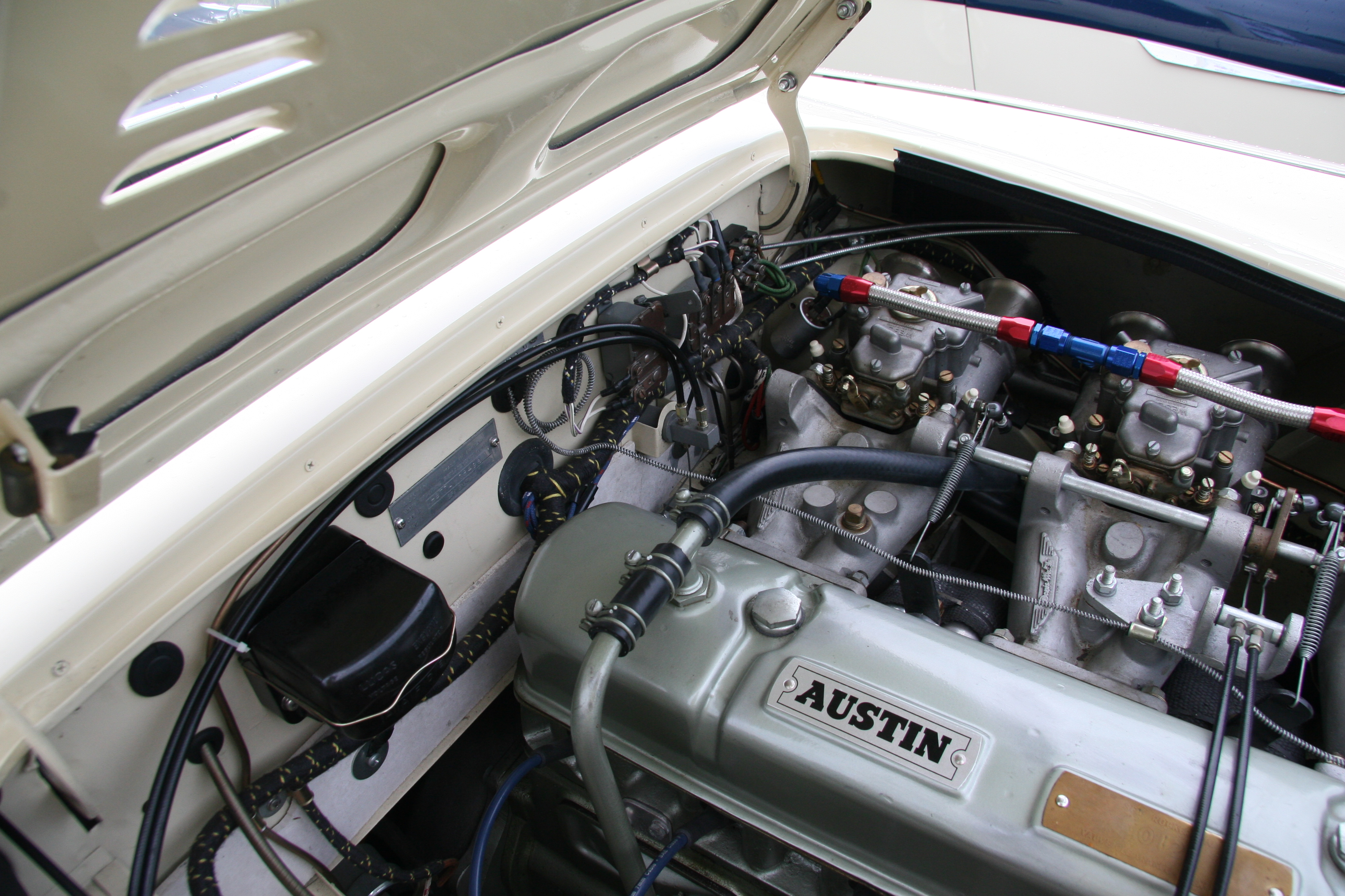
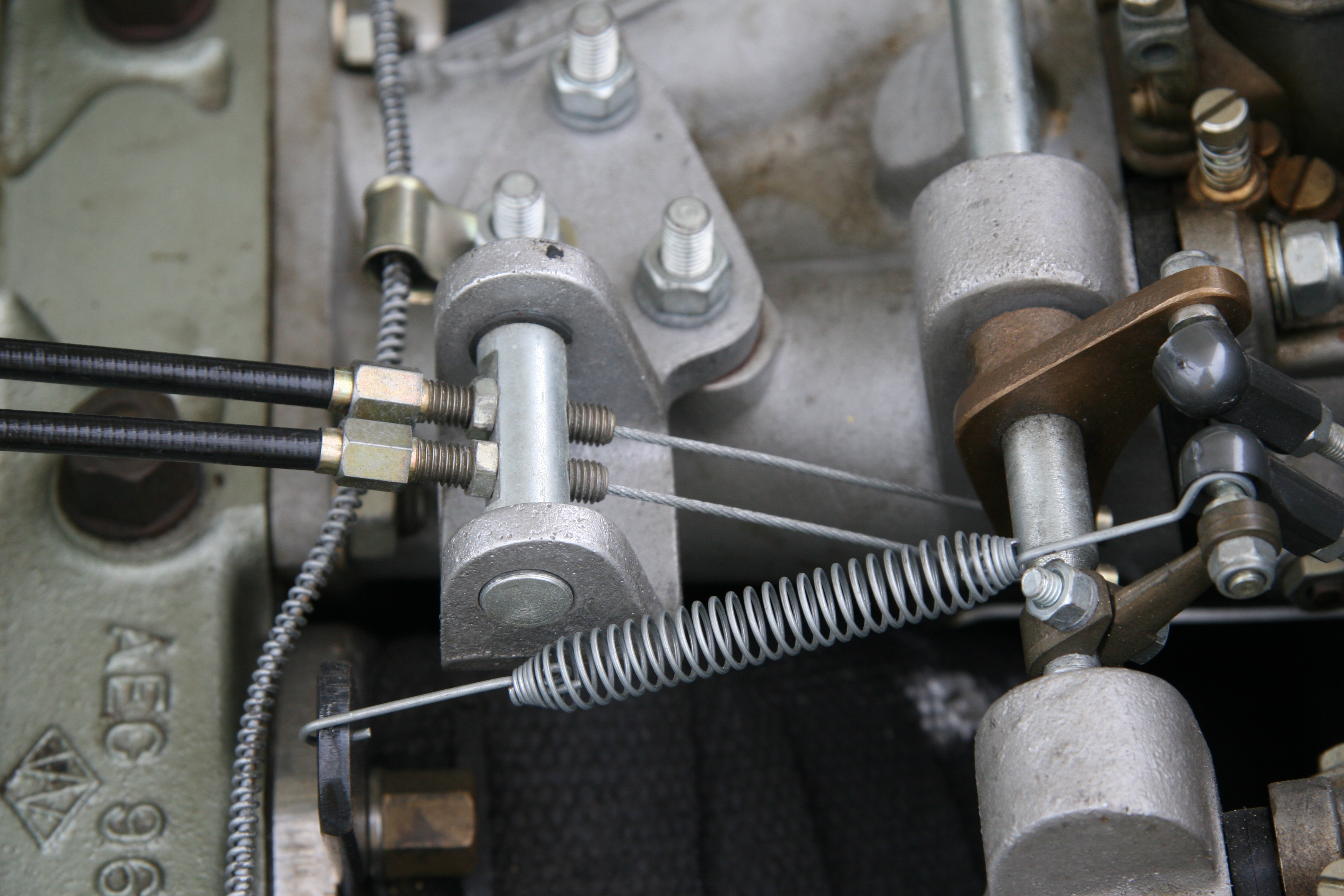
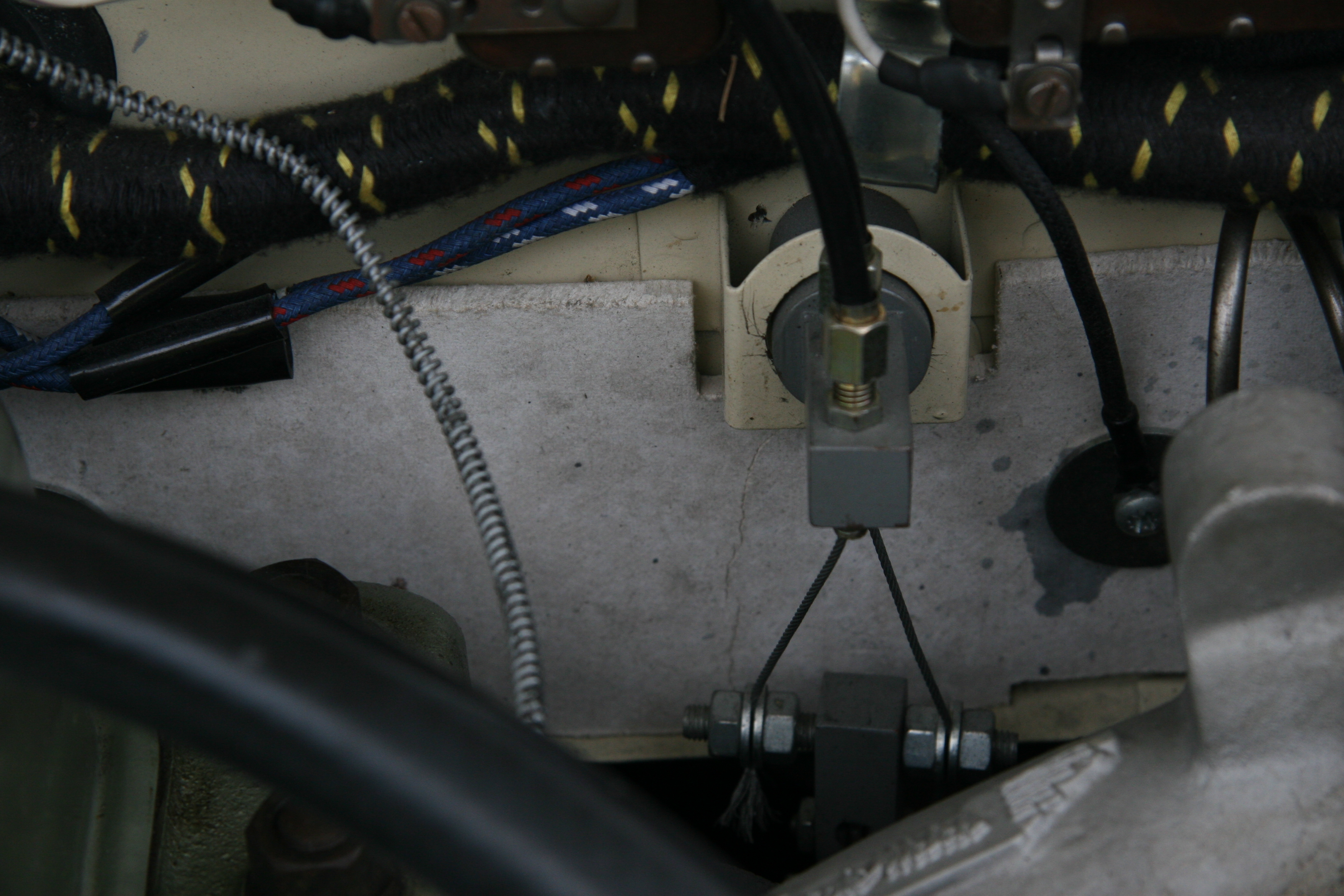
I don’t know who owns the car, but I recently came across some images of a throttle cable conversion that is accomplished quite well in my view. There is a long cable run, but it is well executed. This car uses Webers instead of SUs but the approach is the same. Apologies to the owner if he/she is unhappy sharing this nice work:
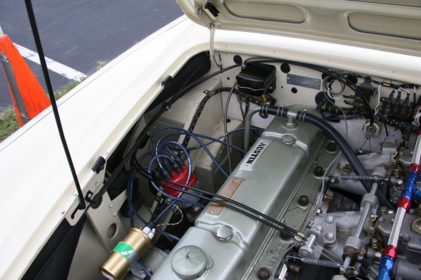
Throttle Cable Routing
Throttle Cable Routing
Manifold Mounting
Firewall Mounting
Firewall Mounting
I hope this description has been useful to readers who are interested in taking a similar approach. Just as I borrowed from the work of others and modified to my own tastes I would expect others to do the same. Please comment, offer suggestions as you like.
While the article does not format as well in a pdf document. for those readers who want to save this as a pdf or for those who want to print it as a pdf, this is the link:Throttle Cable Modification – Valve Chatter


