Engine/Gearbox Installation

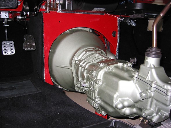
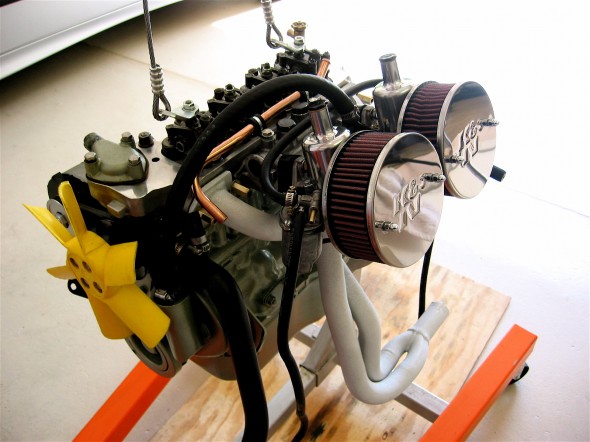
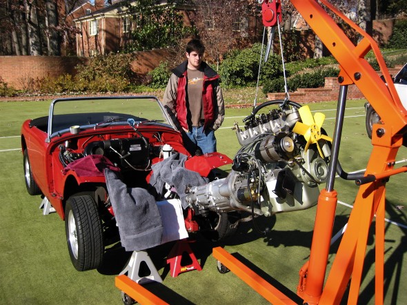
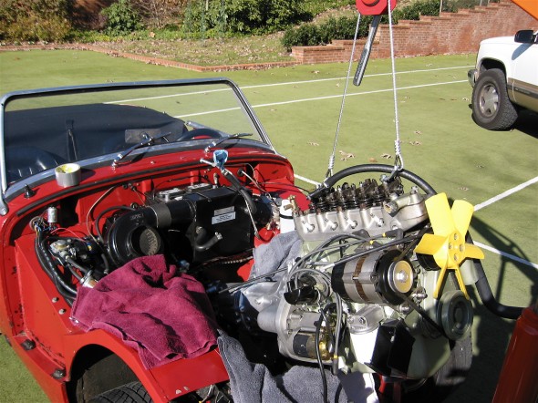
John and Molly came over to assist in the “Big Lift,” the installation of the engine and gearbox into the car. This has been a long time coming. As a reminder, we are installing the 1275 engine along with a Datsun 210 5-speed gearbox. The following image shows the same procedure twenty years go!

Engine Install 2005

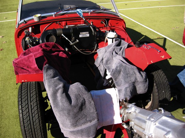
Unfortunately, many have reported that the heater plenum needs to be “bashed” upward to provide clearance for the entry of the gearbox. We had hoped that we could avoid this step if we were very careful and took our time, but it was not to be. In the end we had to “adjust” the plenum to make room. That process is shown in the accompanying video. 

We put together a check list of items that combines preparation steps along with necessary connections to get the engine in and then make it ready to start.

Remove Bonnet – struts and hinges.take the strut off first. before removing the bonnet hinges disconnect the Deutsch connector and the spade connector at the horn.

Jack Stands – place the car on jack stands.

Engine Hoist Leveler – Remove rocker cover and install leveler on engine.

Engine Mounts – Move rubber buffer from engine stand to the car mount.

Starter – Attach the power cable to the starter that will connect to the starter switch later in the process.

Battery Ground cable to firewall – disconnect during engine install.

Engine fan –  install six blade fan and spacer. Install fan belt and check tension.

Crossbar protector – put the custom-made sheet metal protector over the steering rack crossbar to avoid damaging the paint.

Remove fluids –  from engine, radiator and transmission

Timing marks – make sure these are visible on the pulley before installing the engine.

Driveshaft Prop – Grease the yoke and the transmission splines.

Slave cylinder – check threads of the two mounting bolts, should be metric. The threads of the push rod extend beyond the arm by approximately one half inch (6-8 threads showing). The excess on the spacing shim goes to the front of the engine. Find the slightly shortened Allen key for the new cap screws.

Engine Mounts – Install the left-hand engine mount onto the chassis and leave it loose. Install the right hand engine mount onto the engine and leave it loose.

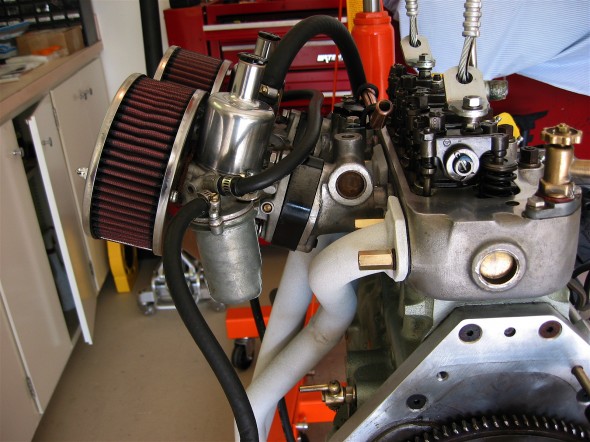
Header – Set the exhaust header in place so that it will be positioned to install once the engine is in place.

Engine/transmission install with engine hoist – Check to see if the heater plenum will require modification. Before the assembly is all the way home push the driveshaft yoke into the rear of the transmission.

Transmission mount – install the ⅜” – 24 x 3 ½” bolts through the chassis and into the mount and tighten. Next, tighten the front engine mounts. Now center the transmission in the rear mount and tighten the transmission pad mounts. Install the bolts in the sides of the rear mounts from the inside of the car with the self locking nuts inside the tunnel. It may be helpful to tape the nuts in the wrench to make starting the threads easier.

RadiatorIt is a little tricky to install. It works best to begin with the upper right (passenger side of the car) mounting point first, then the lower right, followed by the upper left mount and finally the lower left mount. 

Radiator hoses – connect and clamp

Overflow coolant tank – determine right place for the overflow tank drain line and install a fitting in hose. Connect the radiator overflow to the tank.

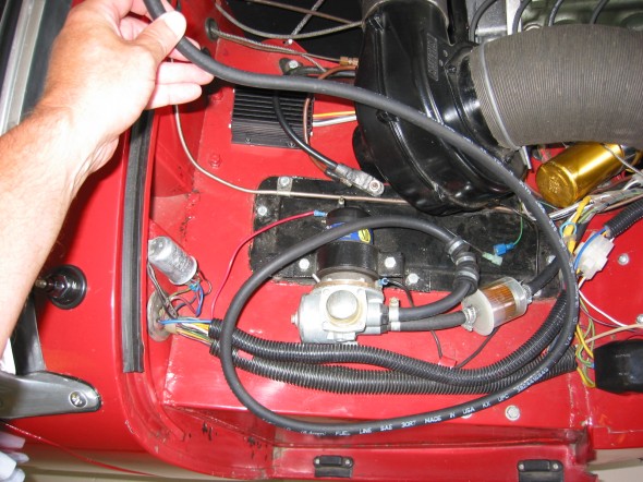
Alternator – connect the wiring for the alternator.

Vacuum Pipe – connect the vacuum hose from the distributor to the carburetor.

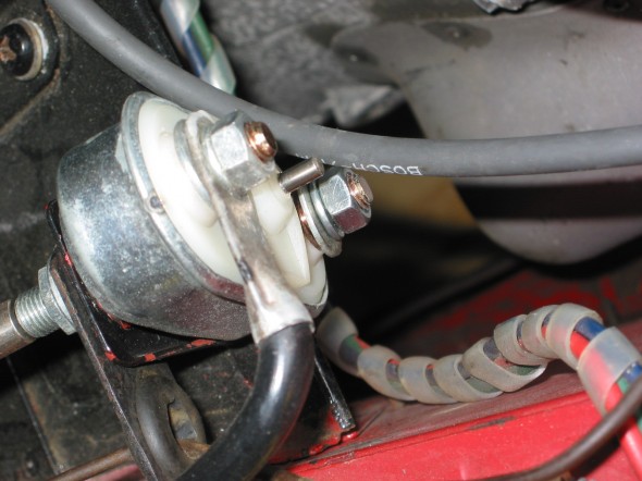
Starter – attach the power cable from the starter to the starter switch.

Ignition Coil – attach the wiring to the coil and distributor. Connect the high tension line from the distributor.

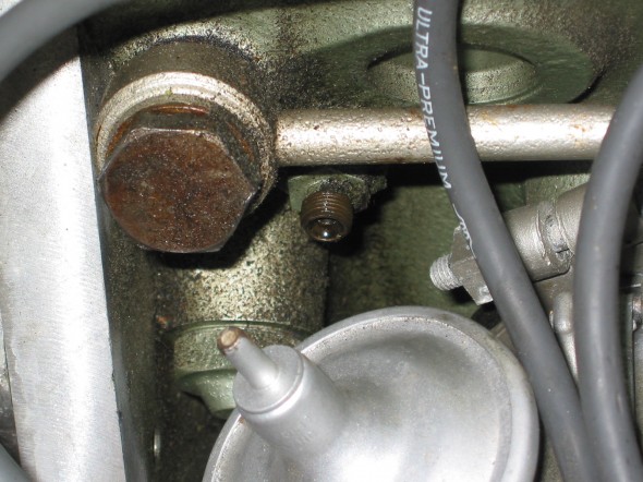
Oil pressure gauge pipe/hose – connect to engine.

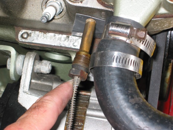
Water temperature gauge – connect capillary tube two cylinder head.

Rocker Cover – install the rocker cover.

Breather hose – connect the hoses and clamp

Driveshaft – connect and tighten bolts/nuts.

Refill fluids in engine, radiator and transmission – transmission requires 2 ¼ pints of Redline MT-90.

Clutch – Bleed the clutch master and then the slave cylinder. To eliminate all air, the slave cylinder piston should be held in the fully retracted position while bleeding. Do this by running out the adjustable push rod until it is pushing firmly on the clutch fork. Keep the master cylinder reservoir topped up while slowly and gently pumping the clutch size cylinder Into operating position. A power bleeder works well here.

Adjust the push rod length to give some free travel at the clutch pedal. Assure clutch is releasing fully while the vehicle is still up on jack stands. Confirm free play assuring that you can move the clutch operating lever away from the clutch slave cylinder push rod. Finger pressure against the lever should be able to move it against the pressure of the spring inside the Bell housing. Generally 1/4 inch to 1/2 inch of free play measured at the fork will be adequate. Be aware that the clutch pressure plate can be over traveled. If the clutch releases when the pedal is partway down, but then seems to reengage at full pedal down. It is being over traveled. Add free play until this condition disappears.

https://youtu.be/k11eIyfErMY?si=YUO94N5qavN61VFl

Battery ground cable to firewall – reattach.

Ground Strap – Attach engine to frame

Intake and Exhaust Manifolds with gasket – brass long nuts

Carburetor –  install heat shield, phenolic spacer, choke and accelerator cable. Connect fuel hose from pipe to carb. Connect vacuum hose to distributor. Put ATF in the carb piston. Connect carb drain hose.

K&N Air Cleaner – Install and spray with special oil.

Heater hoses – attach both and clamp

Exhaust system – install, exhaust header, exhaust pipes, and muffler.

AFR gauge – connect gauge to the O2 sensor and power.

Gasoline – partially fill fuel tank with gasoline.

Battery – reconnect the battery ground cable to the firewall.

Start engine!


These things always take longer than expected, or at least hoped! However, at the end of the day, all that is important is that you got the “thing” in. Well, it was about the end of the day and we did get it in!

We did install the new slave cylinder sourced from Will Perry at Rivergate before the engine went into the car. Once the engine is installed there is not much room between the gearbox and the frame making it a tight squeeze to install the slave cylinder. We are also using a remote bleeder with a flexible hose.

Slave cylinder install

Bugeye Restoration Video Episode One Hundred-One shows the process involved in the installation of the engine and gearbox as well as the short-throw gear shifter sourced from Gerard Chateauvieux at Gerard’s Garage.

https://vimeo.com/1076516667/7bc5103b4c?share=copy

Additional information about Gerard’s shifter is provided in another post: https://valvechatter.com/?p=13520

Bugeye Restoration Video Episode One Hundred-Three shows the process involved in making the various connections required to prepare the engine to start and the gearbox to operate properly. This video will be posted when complete. 

Quick Throw Short-throw shifter for the Bugeye

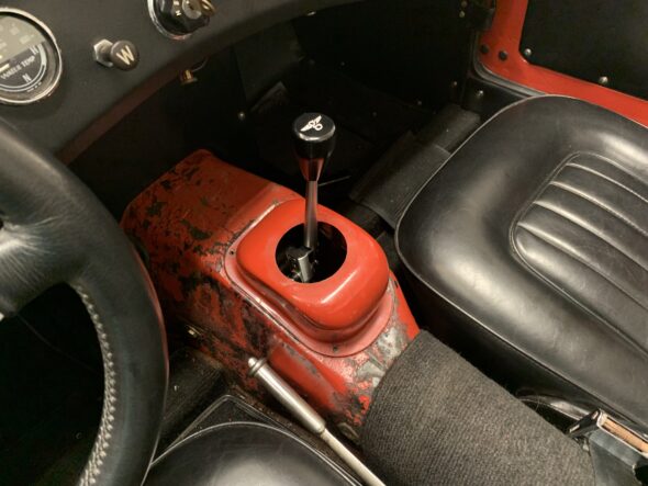
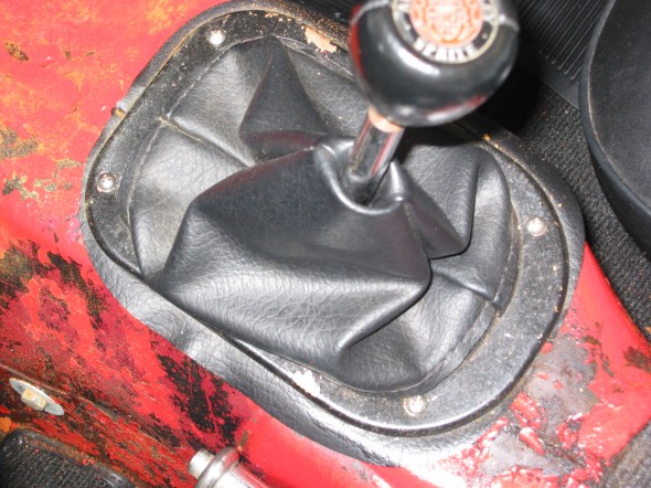
We always wanted to use the original cover for the gearbox shifter because it just seems so uniquely Sprite/Midget. However, we installed a Datsun 210 gearbox so we had to use a leather boot since the gear shift fouled against the cover. 

We were able to purchase what we believe to be the last quick throw gear shift assembly that Gerard Chateauvieux (Gerard’s Garage) fabricated. This will give us the benefit of the short throw or shifting and we should be able to use the original cover. Gerard’s kit is very nicely machined.

The Episode Four video shows the shifter conversion

https://vimeo.com/744791938/346e976572

The Shifter Kit Components

The cap screws require thread locker to insure that everything stays together!

Wedges installed to lift shift fulcrum point

Shifter in place with spacing block and delrin bushes

fulcrum pin with circle

Leather Boot used with 210 gearbox shifter

Original Cover with Gerard’s Gear Shift

Clutch/Gearbox and Propshaft Assorted Modifications

The system consists of the clutch, gearbox, overdrive, and propshaft. The original driveline system included the following:

Clutch: 10” Borg and Beck hydraulic

Gearbox: “side-shift” 4 speed

Overdrive: Laycock de Normanville electric

Propshaft: Hardy Spicer universal joints

Flywheel: 28 lb.

Driveline Modifications

Toyota 5 Speed Conversion

Although I always enjoyed the Laycock de Normanville electric overdrive in my car, I knew my tranny needed to be rebuilt. Rather than go that route, I took advantage of Smitty’s five speed conversion kit and installed a Toyota gearbox in the Bloody Beast. The Toyota Gearbox is quite a bit lighter and folks say that it runs  a bit cooler than the original box.

Gearbox and Bell Housing Installed

Gearbox and Bell Housing Installed

You can use a number of different Toyota gearboxes from the non-turbo Supras or from several of the 2 wheel drive pick-ups. I used a W57 1998 Toyota Tacoma 4×2 VIN# 4TANL42N2WZ094878. Details are available in the restoration blog, but this pdf document put together by Tracy Drummond is very helpful. Drummond Five speed gearbox conversion.

The kit includes several custom components including a bell housing casting unique to the conversion.

The kit is no longer available from Smitty, but Pete Delaney now handles the product. His contact information is as follows as of July 10, 2012:

Stephanie & Pete DelaneyHealey 5 Speed
P O Box 561
Harrisburg, NC 28075
704-455-2585704-455-8504 FAX
Healey5Speedaol.com

Clutch Conversion

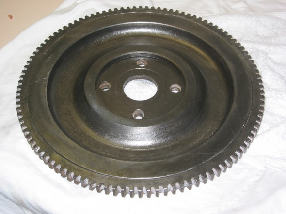
Many who have the early 3000s and who complete the 5 speed conversion also adopt the BJ8 9/12″ diaphragm clutch. It is less demanding on the left leg muscles. I went ahead and made this conversion while I was at it. This also requires using a BJ8 flywheel. I obtained a 24lb. lightened flywheel from Bill Bolton.

BJ8 lightened Flywheel

BJ8 lightened Flywheel

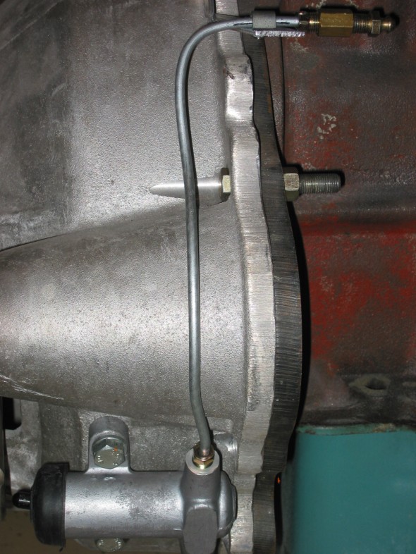
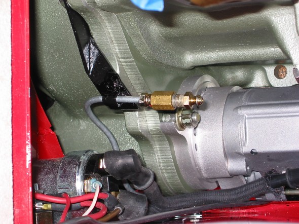
Slave Cylinder Bleeder Pipe Extension

Anyone who has bled a Healey slave cylinder knows that the bleed nipple is not exactly easy to get to. Doug Reid aka “Mr. Finespanner,” fabricated an extension for me that makes the job much easier with the bleeder actually accessed from the engine bay. This has now become a popular item used by many aficionados.

Slave cylinder bleeder

Slave Cylinder Bleeder Extension

Slave cylinder bleeder extension

Slave Cylinder Bleeder Extension

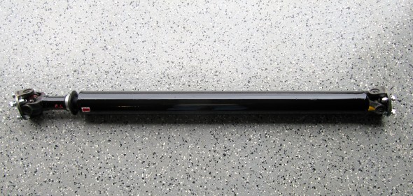
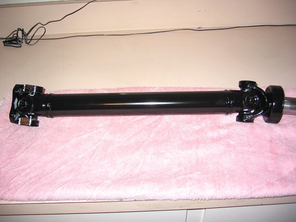
Custom Propshaft

Installing the Toyota 5 Speed does require making up a new propshaft, which I had done at a local speed shop. The propshaft does need to be balanced prior to installation.

Propshaft

Propshaft


zz

Gearbox, Clutch and Propshaft

Clutch and Gearbox

Clutch Master Cylinder

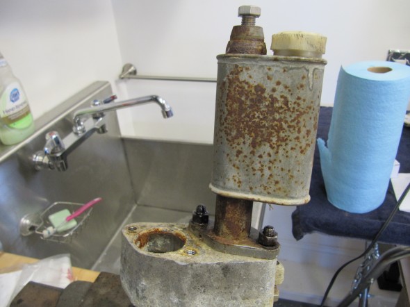
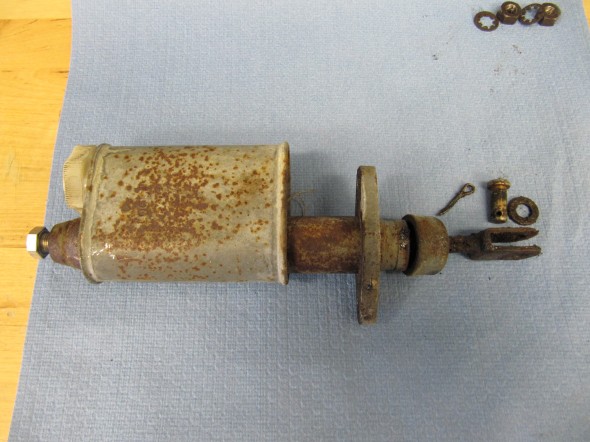
I will replace the master and reservoir seen here with a new unit.
Clutch Master/Reservoir
Clutch Master/Reservoir

Clutch Master/Reservoir

Clutch Master/Reservoir

Since the clutch master and the brake master share the same housing and pedal box, information about those components is addressed under the brake servo and hydraulics post at this link: https://valvechatter.com/?cat=615
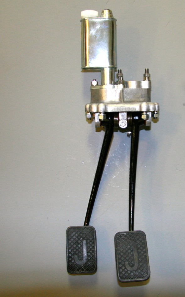
Clutch Master Cylinder, Reservoir Mounted to Housing with new Pedal Rubber

Clutch Master Cylinder, Reservoir Mounted to Housing with new Pedal Rubber

Bracket for Flexible Clutch Hose at Rear of Cylinder Head

This little bracket is in a conspicuous location and called for re-chroming.
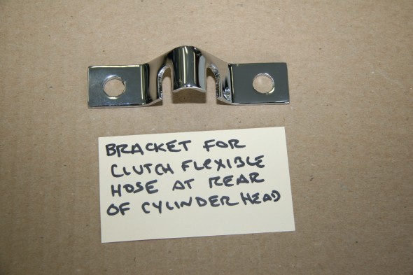
Clutch Flexible Hose Bracket at Rear of Cylinder Head

Clutch Flexible Hose Bracket at Rear of Cylinder Head

Slave Cylinder Hydraulic Pipe

A hard line attaches to the flexible stainless steel hose at the cylinder head bracket (shown above) and connects to the slave cylinder. It is held securely by one clip attached to the bell housing. The new line was sourced from Classic Tube along with the pre-bent brake lines.
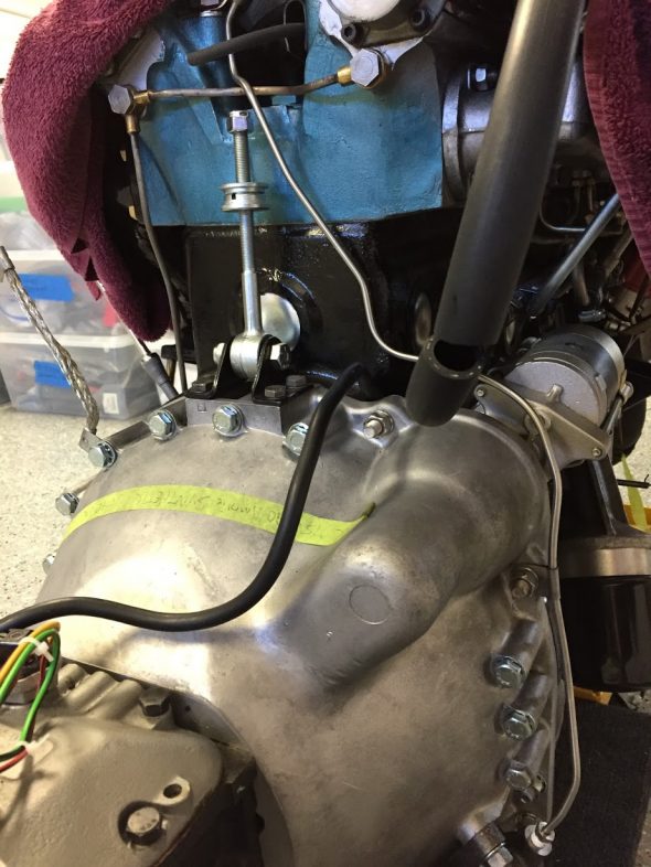
Slave Cylinder Hydraulic Line

Slave Cylinder Hydraulic Line

Clutch

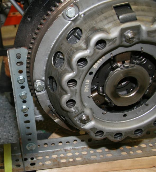
The 1964 MK2 used a spring-loaded, hydraulically-operated, driven plate assembly with cover and a graphite release bearing. Later models switched to a diaphragm clutch. While the diaphragm cultch is probably easier to operate, I decided to stick with the original type in my restoration. The entire clutch assembly was purchased from SNG Barratt and installed by my engine builder, Mike Gassman, from Gassman Automotive. The unit was balanced with the engine for smoother running.
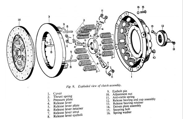
MK2 Clutch Diagram
MK2 Clutch Diagram

MK2 Clutch Assembly
MK2 Clutch Assembly

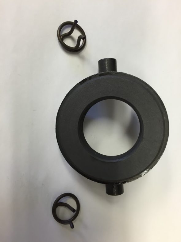
Release Bearing and Clips
Release Bearing and Clips

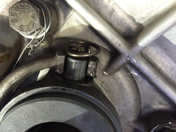
Release Bearing Mounting Clips

Release Bearing Mounting Clips

Clutch Slave Cylinder

Fortunately, the replacement slave cylinder sourced from SNG Barratt is exactly the same as the original. the rubber boot is somewhat different, but otherwise identical. The new return spring is; however, shorter than the spring currently on the car. Not sure if it is a different spring or if the original is stretched. In any case, I shall try the new one (which did have the proper Jaguar part number) and see how everything functions.
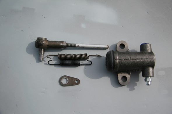
Slave Cylinder Assembly

Slave Cylinder
Assembly

The Jaguar Service Manual states that “there should be 3/4″ free travel or unloaded movement at the pedal pad before feeling the resistance of the clutch thrust springs. The free travel is most easily felt by depressing the pedal pad by hand until a marked resistance is felt. Adjustment is effected by slackening the lock nut and turning the operating rod between the slave cylinder and the clutch withdrawal lever. Screwing the rod into the knuckle joint will increase the pedal travel; screwing the rod out will decrease the free travel.”
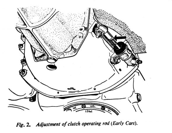
MK2 Clutch Slave Cylinder Adjustment

MK2 Clutch Slave Cylinder Adjustment

Gearbox and Overdrive The gearbox is a four-speed type with synchromesh on the second, third, and top gears. The overdrive is a Laycock de Normanville. First and reverse gears are 12.731:1, Second is 7.012:1, Third is 4.836:1, and fourth is 3.77:1; with the overdrive engaged the top gear ratio is 2.933:1. A synchronized fiord gear was added later in production.

According to Nigel Thorleys excellent book – Original MK1/MK 2 the all synchro box was fitted in Sept 1965 from chassis no 119200 – 2.4 RHD 127822 – 2.4 LHD 169341 – 3.4 RHD 180188 – 3.8 LHD
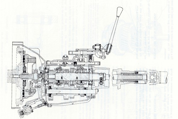
MK2 Gearbox
MK2 Gearbox


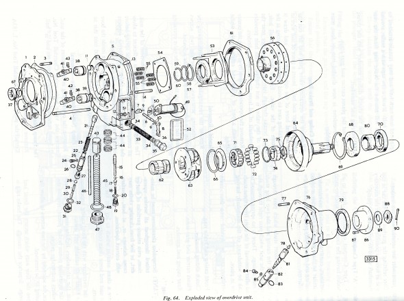
MK2 Overdrive

MK2 Overdrive

Mike Gassman, http://www.gassmanautomotive.com refreshed the overdrive and the gearbox was sent to Quantum Mechanics in Connecticut. Both units were in good repair with the exception that the 3rd to fourth shift fork was bent and was replaced. The gearbox also had all bearings, synchronizers, seals and gaskets replaced. The gears were in good shape. The overdrive was cleaned, an overdrive rebuild kit installed and reassembled in good working order. A new solenoid was affixed and the system was tested.

Change-Speed Lever Assembly (Gear Shift) The  change-speed lever has single flat washer above the selector lever.

There is a two part rubber bush inside the selector lever through which the selector shaft passes. There is a flat washer at each end of the bush. The washers have different diameter holes appropriate to the shaft size at each end of the lever. I cleaned the selector lever and painted it with POR-15. New rubber bushes were also installed.
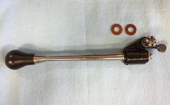
Change-Speed Lever
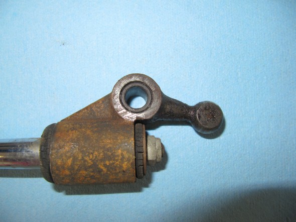
Change-Speed Lever

Selector Lever

Selector Lever

Painted Selector Lever
Painted Selector Lever

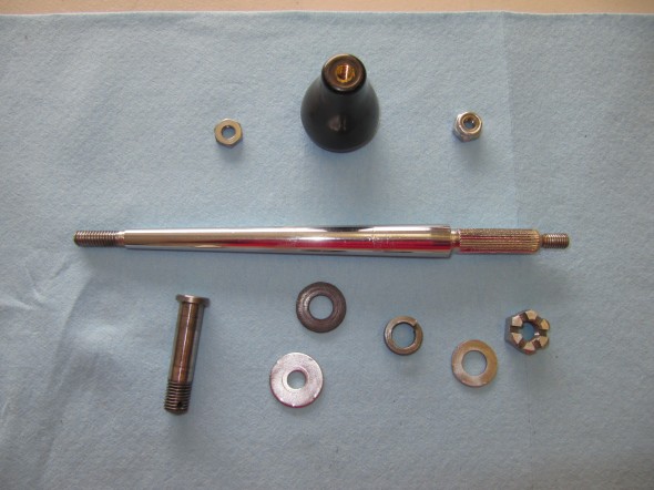
Assembly Components

Assembly Components

There is a bronze bushing in the selector lever through which the pivot pin passes. This bush was also replaced with a new component. A new fiber washer is located on each end of the pivot pin. A double spring washer  is located on the pivot pin and the assembly is held together with a slotted nut and a split (cotter) pin.
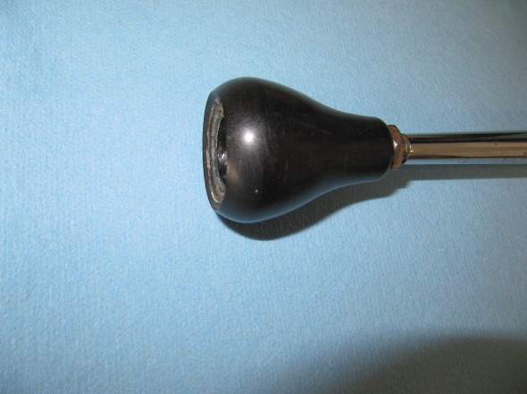
Change Speed Lever Knob

Change Speed Lever Knob

The correct lever knob for the early Moss gearbox (without first speed synchro) is a tear drop shape. The later box used a round shifter ball. A locking nut secures the shift knob to the shaft.

I ordered a new lever shaft and discovered that what is being supplied now is 3 inches shorter than the original. I will probably have my original lever shaft rechromed and use it.
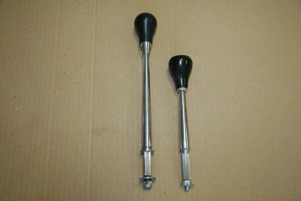
Original Shifter on Left and New Part on Right

Original Shifter on Left and New Part on Right


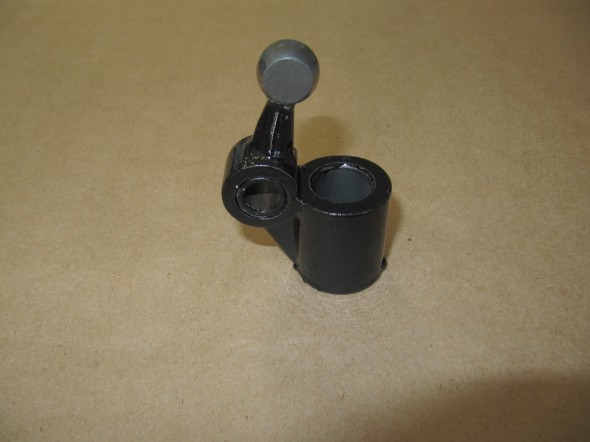
Pivot Jaw Holding Selector Lever

This device connects the Change-speed Lever (gear shift) to the Gearbox Top Cover. In the image below it is the black yoke which was cleaned and painted with POR-15.
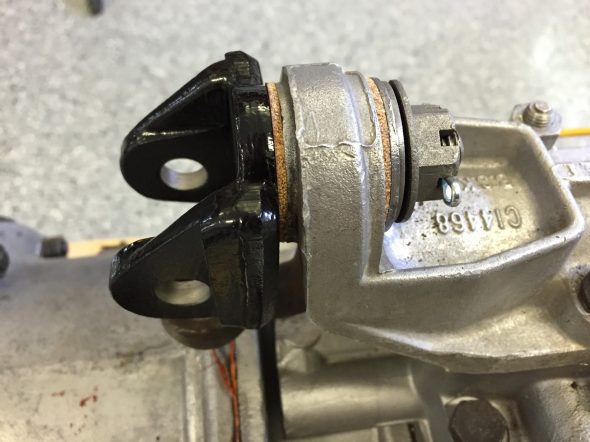
Pivot Jaw Housing Selector Lever

Pivot Jaw Housing Selector Lever

The following image shows the components of the Pivot Jaw assembly: The Pivot jaw, two fibre washers, a bushing, a flat “D” washer, a spring washer and a slotted nut with split pin.
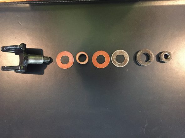
Pivot Jaw Assembly Components

Pivot Jaw Assembly Components

This image shows the Pivot Jaw Housing, the Change-speed Lever, and the Selector Lever all assembled and in place on the gearbox:
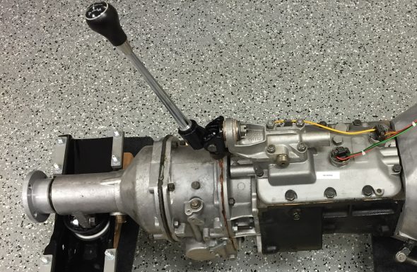
Assembled Gear Selector Assembly

Assembled Gear Selector Assembly

Fasteners for Gearbox to Engine The original fasteners were in good shape, no doubt due to the thick coat of oil and grease that encapsulated them! I media-blasted the bolts and nuts and had them zinc plated for use upon reassembly. There are eleven hex head bolts 3/8″ – 24 x 2 7/8″ with two 3/8″ – 24 nuts and shakeproof washers, and four 3/8″ – 24 x 1 3/8″ hex head bolts with four 3/8″ – 24 nuts and shakeproof washers.
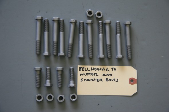
Bellhousing fasteners

Bellhousing fasteners

Cover Plate at Front of Clutch Housing  The cover plate is fastened to the engine backplate with four #10-24 x 1/2″ hex head bolts and shakeproof washers. It is installed when the gearbox is mated to the engine when the two components are separated by approximately 2″. At that time the cover plate is slid into position and tightened against the lip of the gearbox bell housing with the four bolts.
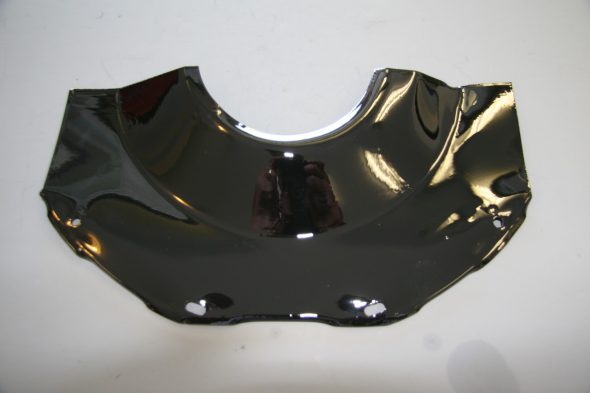
Clutch Cover Plate
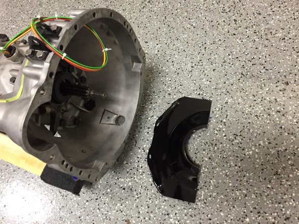
Clutch Cover Plate

Clutch Cover Plate at Bell Housing

Clutch Cover Plate at Bell Housing

Gearbox/Engine Mating

On June 18, 2016 in preparation for the preliminary installation of the engine and gearbox into the car for testing, I mated the two components together using the bolts referenced above. In the cases where nuts are used, all nuts are found on the bell housing side. I had to wrestle with the gearbox a bit to get it to seat properly, but I eventually got there. One must be careful to keep the gearbox mainshaft level with the crankshaft to avoid bending the shaft.
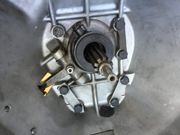
Gearbox Mainshaft

Gearbox Mainshaft

I used my engine hoist to hold the gearbox at proper height during the exercise. Several long 3/8″ bolts were used to align the bell housing and the backplate of the engine, prior to inserting the proper bolts and pushing the gearbox home. As mentioned above, then the two components are approximately two inches apart, the clutch cover needs to be inserted and bolted in place.
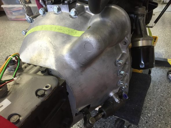
RH Side of Bell Housing Mounted to Engine
RH Side of Bell Housing Mounted to Engine

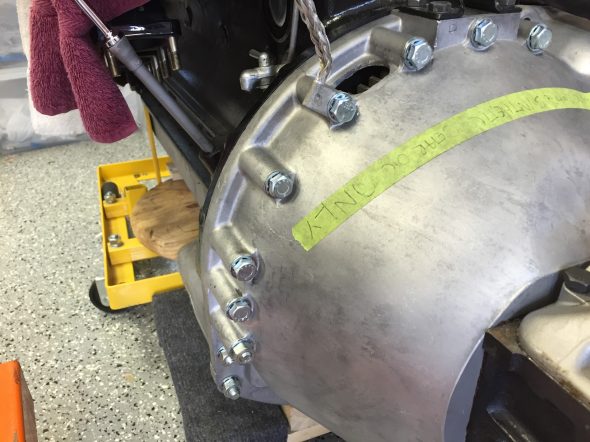
LH Side Of Bell Housing Mounted to Engine

LH Side Of Bell Housing Mounted to Engine

Ground Strap

The ground strap was connected to the engine/bell housing prior to installation in the car. A new ground strap was sourced from SNG Barratt. Note the proper location of the strap:
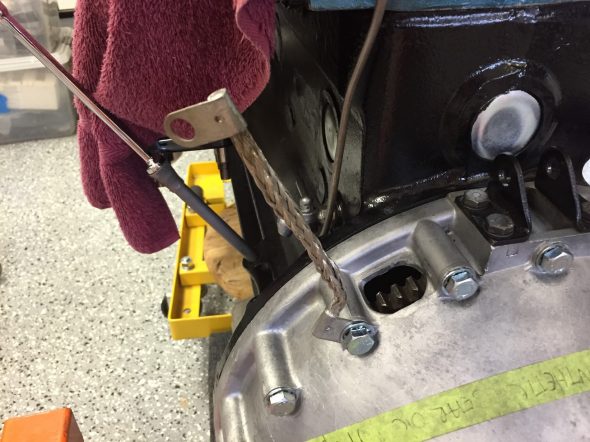
Ground Strap Mounted

Ground Strap Mounted

Propshaft

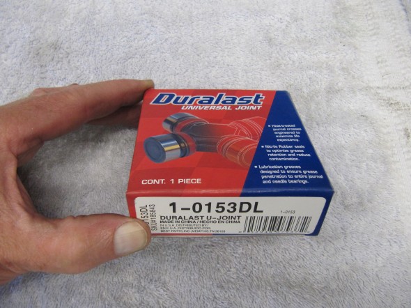
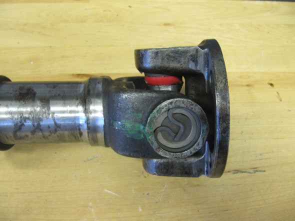
The propshaft with the two flange yokes attached is just under 48″ long. The shaft seems to be in good shape, but I went ahead and replaced the two universal joint journals and bearings. Following installation of the universal joints I greased the two units and then cleaned the shaft well to send to Driveshaft Specialists in San Antonio, TX  http://www.driveshaftspecialist.com  (Jeff, 866-455-6622) for balancing.
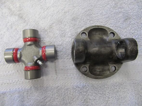
Universal Joint Replacement
Universal Joint Replacement

Duralast Universal Joints
Duralast Universal Joints

Universal Joints Installed

Universal Joints Installed

Upon return from Driveshaft Specialists, I painted the propshaft with POR-15.
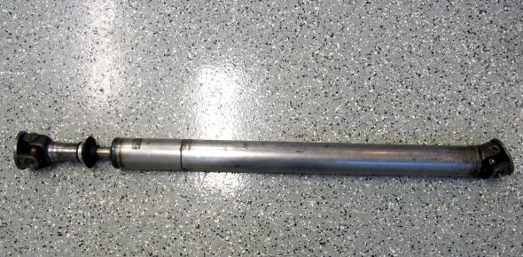
Propshaft with new Universal Joints

Propshaft with new Universal Joint

Balanced & Painted Propshaft

Balanced & Painted Propshaft

Gearbox/Overdrive Lubrication

After installing the engine and gearbox in the car I filled the gearbox and overdrive with oil. Mike Gassman, at Gassman Automotive, recommended using Amalie Elixir Full Synthetic GL-5 Gear Lubricant. The Jaguar MK2 Service Manual indicated that 4-3/4 pints of lubricant should be used.
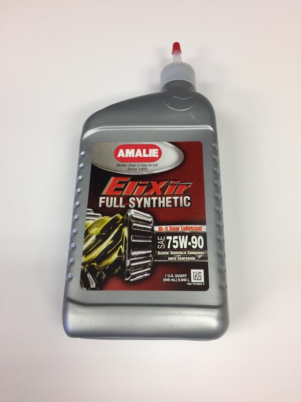
Amalie Elixer Full Synthetic GL-5 Gear Lube 75W-90

This image, although a little out of focus, shows the fill plug near the top and the drain plug at the bottom of the gearbox. The overdrive fills though an internal hole from the gearbox to the overdrive.
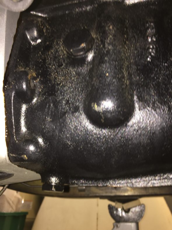
Drain and Fill Plugs for the Jaguar MK2 Gearbox

While I could have used my hand pump to pump the gear lube from below into the fill hole, since my interior is not installed I removed the fiberglass gearbox cover and filled from above. I inserted a clear tube into the fill hole and routed it to the interior. I found that it actually took a little closer to 4- 1/2 pints to fill the units, even after waiting some time to allow the fluid to flow to the overdrive. I filled the gearbox until the gear lube began to leak out of the fill hole.
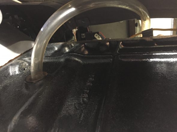
Fill Tube for Gearbox

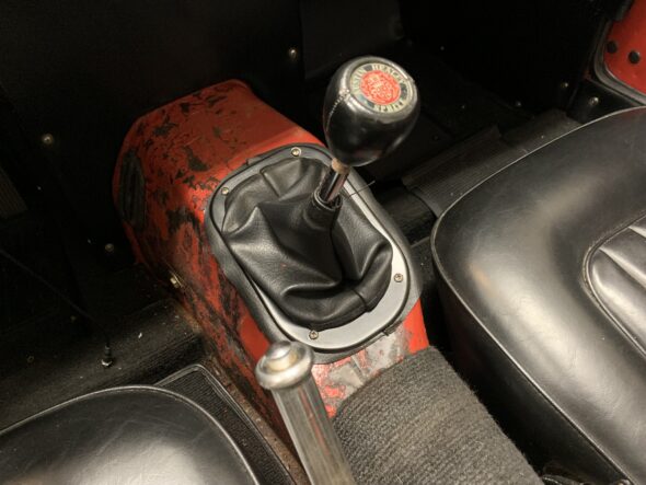
 

Storing the Original 948cc Motor

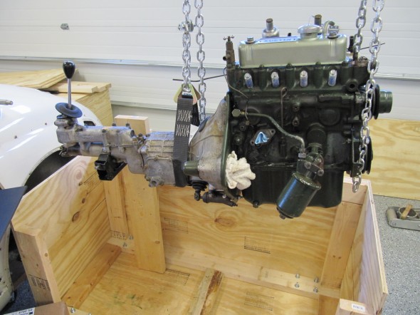
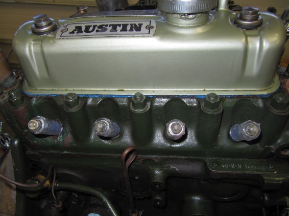
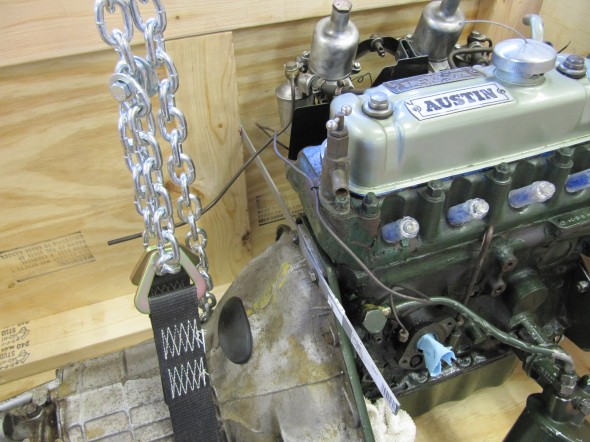
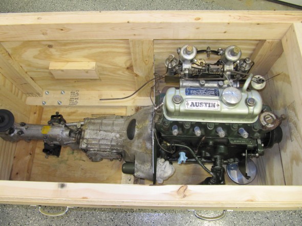
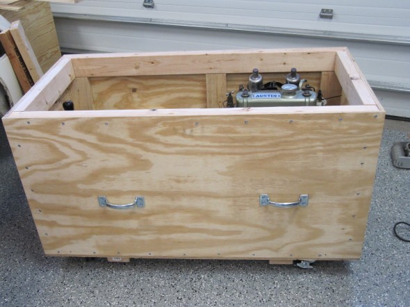
Engine & GearboxMy Dad built a new house and he is “downsizing,” so some car parts are needing to go to a storage unit. When we upgraded to a 1275 motor and Datsun 5-speed gearbox, we kept the original 948cc. I will never plan to go back to the 948, but if the car is ever sold it will be nice to have the original numbers-matching engine. Apparently, the original gearbox was replaced with the ribcase box somewhere in its history..He has a climate controlled unit, but the motor and gearbox needed to be put away properly so he built a nice plywood box for the storage unit.

Fluids were drained, and Marvel Mystery Oil squirted into each cylinder. Desiccant plugs were purchased from Moss Motors and installed in place of the Champions. Holes were plugged and the top of the box was screwed in place. Who knows when this motor and gearbox will see the light of day again!

Desiccant Plugs

Desiccant Plugs

Backplate Brace

Backplate Brace

Tucked in for the Night

Tucked in for the Night

Engine Storage Box

Engine Storage Box

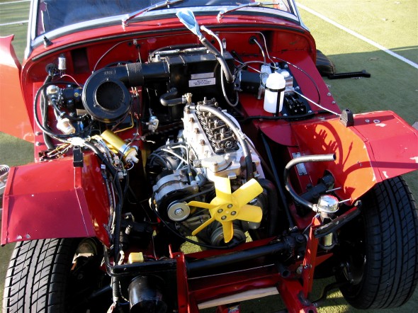
Engine Clean-up and Reinstall

Engine Install

Engine Install

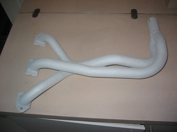
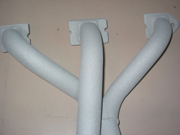
One of the things I wanted to accomplish with the engine clean-up was to have the  exhaust header coated to reduce heat in the engine compartment and interior. I used Swain Coatings. The header came back looking great. Time will tell if the coating holds up and is effective in reducing heat.

Swain Coat Header

Swain Coat Header

Swain Coat Header

Swain Coat Header

I also did a general cleaning of the engine including a new paint job while the gearbox was being worked on by Jack Harper. I replaced the oil sump gasket and the rocker cover gasket, too. I tested and reinstalled the gear reduction starter. The air cleaners were cleaned and oiled with K&N products.

Clean Motor Assembly

Clean Motor Assembly

Clean Motor Assembly

Clean Motor Assembly

I developed the following list of items for reinstalling the engine and gearbox into the Bugeye:

Reinstalling a Bugeye Engine and Datsun 5-speed Transmission

  1. Grease the shaft splines on the engine and the yoke before installing the engine.
  2. Set the exhaust header in place so that it will be positioned to install once the engine is tightened into its mounts.
  3. Guide the motor into place with the lift so that the yoke on the driveshaft lines up with the transmission. If this does not work then remove the driveshaft and install after the engine and transmission are in place.
  4. Loosely secure the engine to the front motor mounts. The mounts themselves should be loose then tightened after all bolts/nuts are in place.
  5. Install the long bolts up through the crossmember into the rear transmission mount and tighten.
  6. Tighten the front engine mounts.
  7. Center the transmission in the rear mount, then push it as far to the right as possible, and tighten the transmission pad mounts on the bracket.
  8. Install the bolts in the sides of the transmission rear mounts from inside the car with the self locking nuts inside the tunnel. (Hint: tape the nuts in the wrench to make starting the threads easier.)
  9. Replace the gearshift lever.
  10. Connect the ground strap to the frame of the car.
  11. Replace the rocker cover and connect the breather hose.
  12. Install the intake and exhaust manifolds.
  13. Install heat shield and carbs.
  14. Connect throttle and choke cables.
  15. Connect breather hose.
  16. Connect hot water hose to copper tube and connect to radiator hose. Tighten clamps. It is easier to put the clamp on the hose/copper pipe when the copper pipe clips are loose from the manifold.
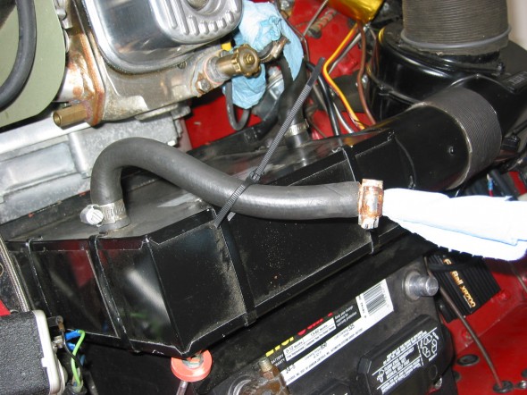
  17. Connect the short hot water hose from the water control valve to the heater.
  18. Connect the electrical cable from the gear reduction starter to the starter solenoid.
  19. Connect the oil pressure pipe to the fitting on the engine block by the banjo bolt.
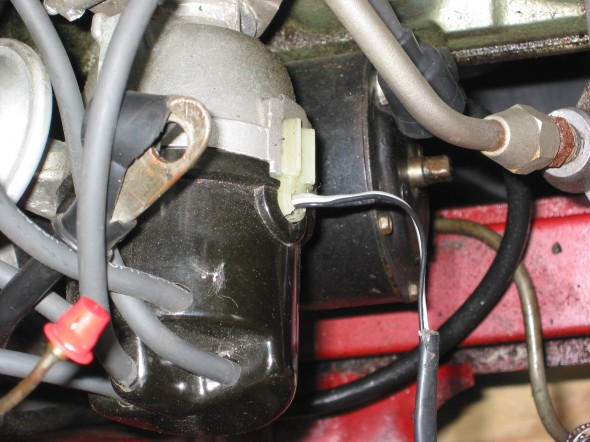
  20. Reconnect the white/black line from the electronic ignition to the distributor.
  21. Connect the high tension line from the distributor to the coil.
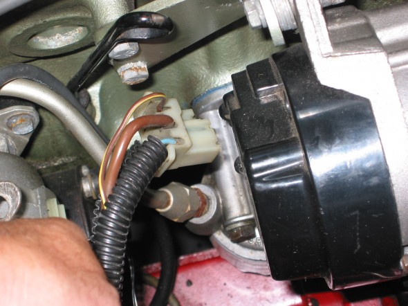
  22. Reconnect the plastic terminal (3 wires) to the alternator.
  23. Connect the fuel line from the fuel pump to the carbs.
  24. Reattach the water temperature sensor to the engine head.
  25. Remove the banjo bolt where the oil line exits the rear of the block. Pour motor oil down the hole in the block to prime the oil pump. Reinstall the bolt.
  26. Remove the oil filter and pour it full of motor oil and reinstall.
  27. Fill engine with oil – Castrol GTX 10W-40.
  28. Fill the gearbox with Gear lube – Redline MT90. 2 1/4 pints. Use long clear plastic tube. Try pump.
  29. Connect the stainless steel flex line from the master cylinder to the slave cylinder.
  30. Bleed the clutch slave cylinder. (See Page 9 of Rivergate’s manual)
  31. Install radiator and fill with 50% coolant and 50% distilled water.
  32. Fix the carb drain lines to the mounting clamp at the lower rear of the engine compartment.
  33. Insert the 1 ½” connecter pipe (with sealant) for the exhaust system into the header pipe.
  34. Install the exhaust and muffler assembly.
  35. Tighten clamps on the exhaust connecter pipe.
  36. Reconnect the battery cables.
  37. When ready to start the engine, pull the spark plugs and spin the engine with the starter until the oil pressure goes up to normal on the pressure gauge, and stays.
  38. Check for any oil, coolant and fuel leaks.
  39. Reinstall the spark plugs and start engine.
  40. If engine does not start turn distributor 180 and try again!
  41. Install 4” fresh air heater hose and clamp.
  42. Install the leather shifter cover and surround.

Start It Up And Have Some Fun!

I Know It Fits!

I Know It Fits!

Motor Protection!

Motor Protection!


Engine Install

Engine Install

Pulling the Engine for Minor Repairs

July 2006 Bugeye It is time to fix some of the problems we have lived with for a while and to make a few improvements. The oil leak we caused when we failed to seal the oil sump properly, the gear grinding in 2nd and 3rdin the gearbox, jet coating the headers among other things will improve the car for the future. These improvements require pulling the engine. We bought a cherry picker and an Oberg tilt lift rather than continuing to rent at $45 a pop. The following details the process to get ready to lift out the engine: Disconnected the battery positive lead from the terminal. Drained the engine oil, tried the gearbox, but couldn’t get the plug out so will return to that. Disconnected the ground strap and removed the two gearbox mounting bolts from the bottom of the car.

ground strap

Ground Strap

Gearbox Mount Bolts

Gearbox Mount Bolts

Disconnected the fuel line at the carbs and pulled out of the way, and disconnected the temperature sensor from the head.

Fuel Line

Fuel Line

Temperature Sensor

Temperature Sensor

Disconnected the oil pressure gauge line and the oil feed line from the engine block, and disconnected the cable from the starter solenoid to the starter.

Solenoid Connection

Solenoid Connection

Oil Temp Connection

Oil Temp Connection

Unsnapped the plastic connector for the white/black line to the distributor from the electronic ignition device, and disconnected the plastic terminal (3 wires) to the alternator.

Ignition Wiring

Ignition Wiring

Alternator Wiring

Alternator Wiring

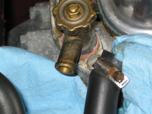
Disconnected the high tension line from the distributor to the coil. Disconnected the short hot water hose from the hot water valve control on the head and then the longer line on the other side of the engine to the copper tube. It is easier to put the clamp on the hose/copper pipe when the copper pipe clips are loose from the manifold.

Water Valve

Water Valve

Heater Hose

Heater Hose

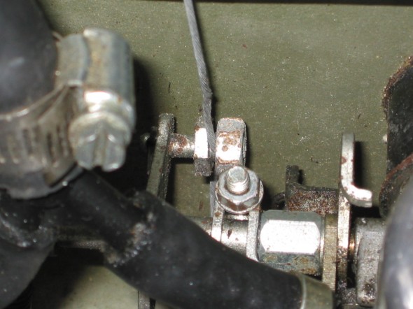
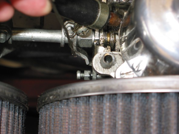
Disconnected the throttle cable at the carb linkage and pulled it out of the way, and then also disconnected the choke cable at the carb.

Throttle Cable

Throttle Cable

Choke Connection

Choke Connection

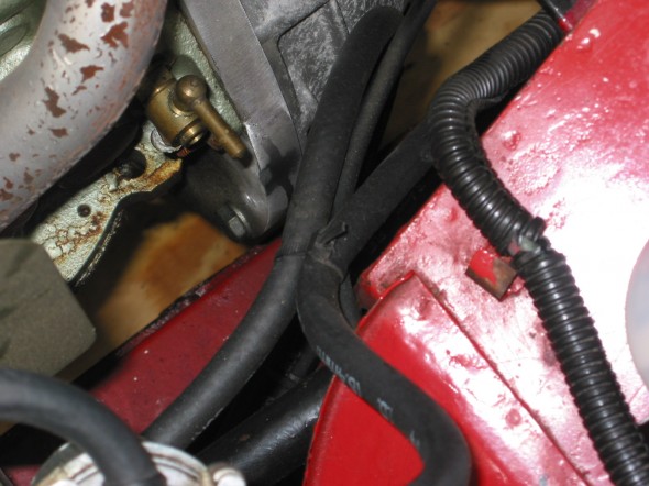
Disconnected the fitting at the slave cylinder (and got brake fluid everywhere).

Fuel Drain Line

Fuel Drain Line


Intake Manifold

Intake Manifold


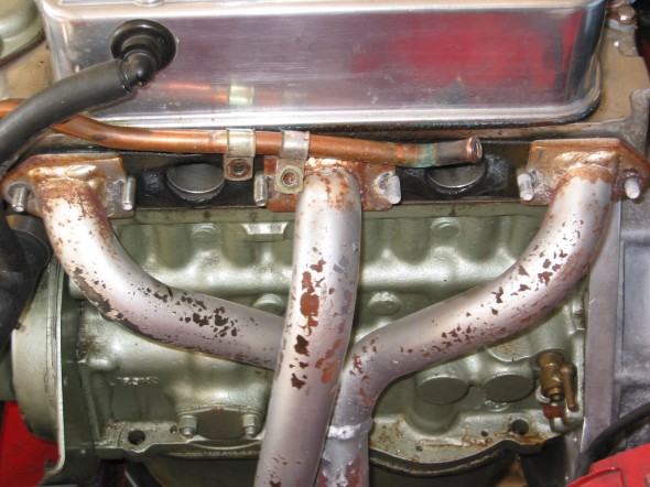
Very Ugly Header

Very Ugly Header

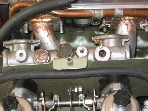
Removed the manifold brass nuts from the head and lifted the intake manifold and carbs free of the engine. The carb drain lines tied together with plastic straps will need to be rerouted to the retainer clips upon installation again. The headers will not come out of the engine bay until the engine is pulled or the heater is removed. Need to set the headers in place prior to the engine install.

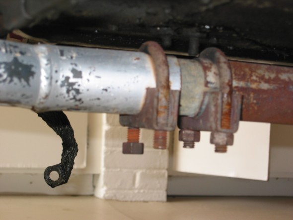
Exhaust Clamps

Exhaust Clamps

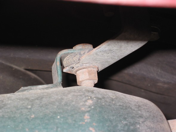
Exhaust Mount

Exhaust Mount


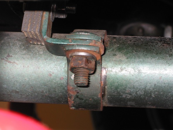
Exhaust Clamp

Exhaust Clamp

Removed four Phillips screws attaching the shift boot to the gearbox tunnel, the shifter knob, and removed two bolts on each side of the tunnel securing the gearbox bracket to the car. Use of the offset wrench made this an easier job.

Shifter Trim Ring

Shifter Trim Ring

Gearbox Rear Mount

Gearbox Rear Mount


Shifter Connection

Shifter Connection

Loosened the right hand motor mount from the car so that it will lift free with the engine, but will not completely disconnect until the engine lift has the pressure off of the mounts. Loosened the screws to the engine at the mount on the left side of the car. The left mount will stay in the car.

Removed the cardboard heater hose to have it out of the way from the engine when it is lifted.

Connected the Lift Chain to the Rocker Shaft mounting studs and lifted the engine from the car.