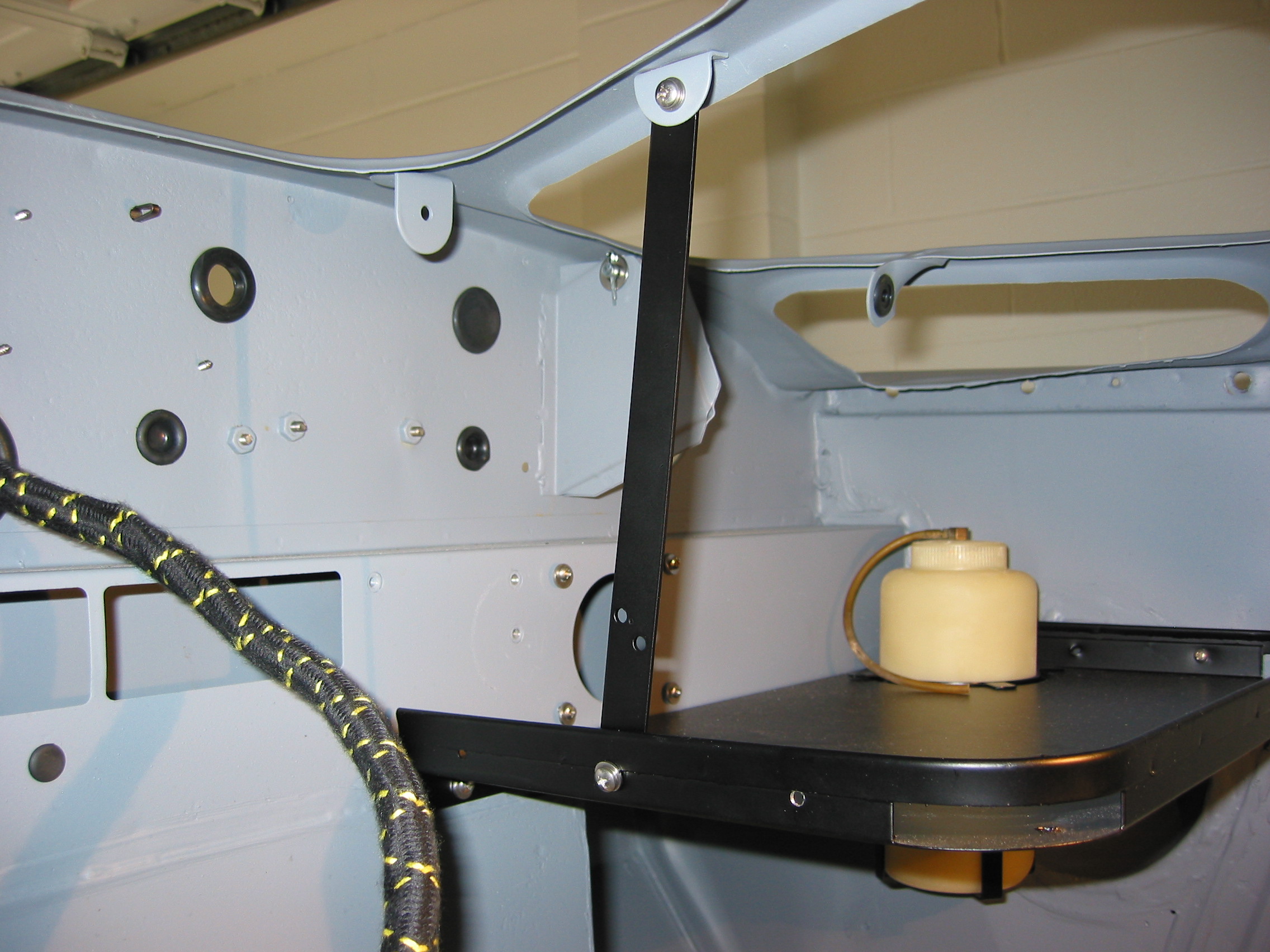
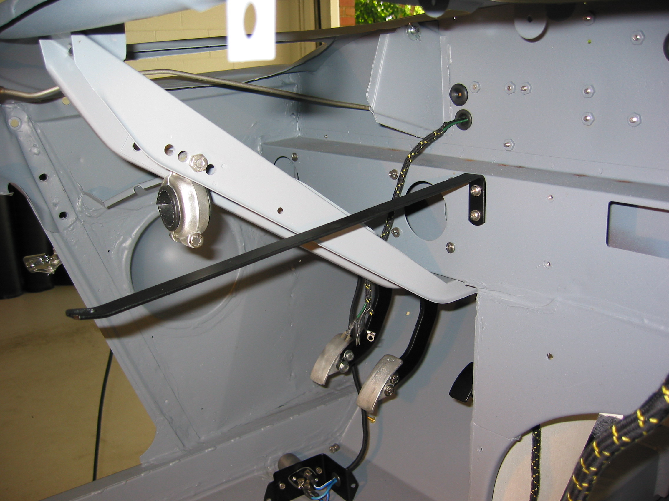
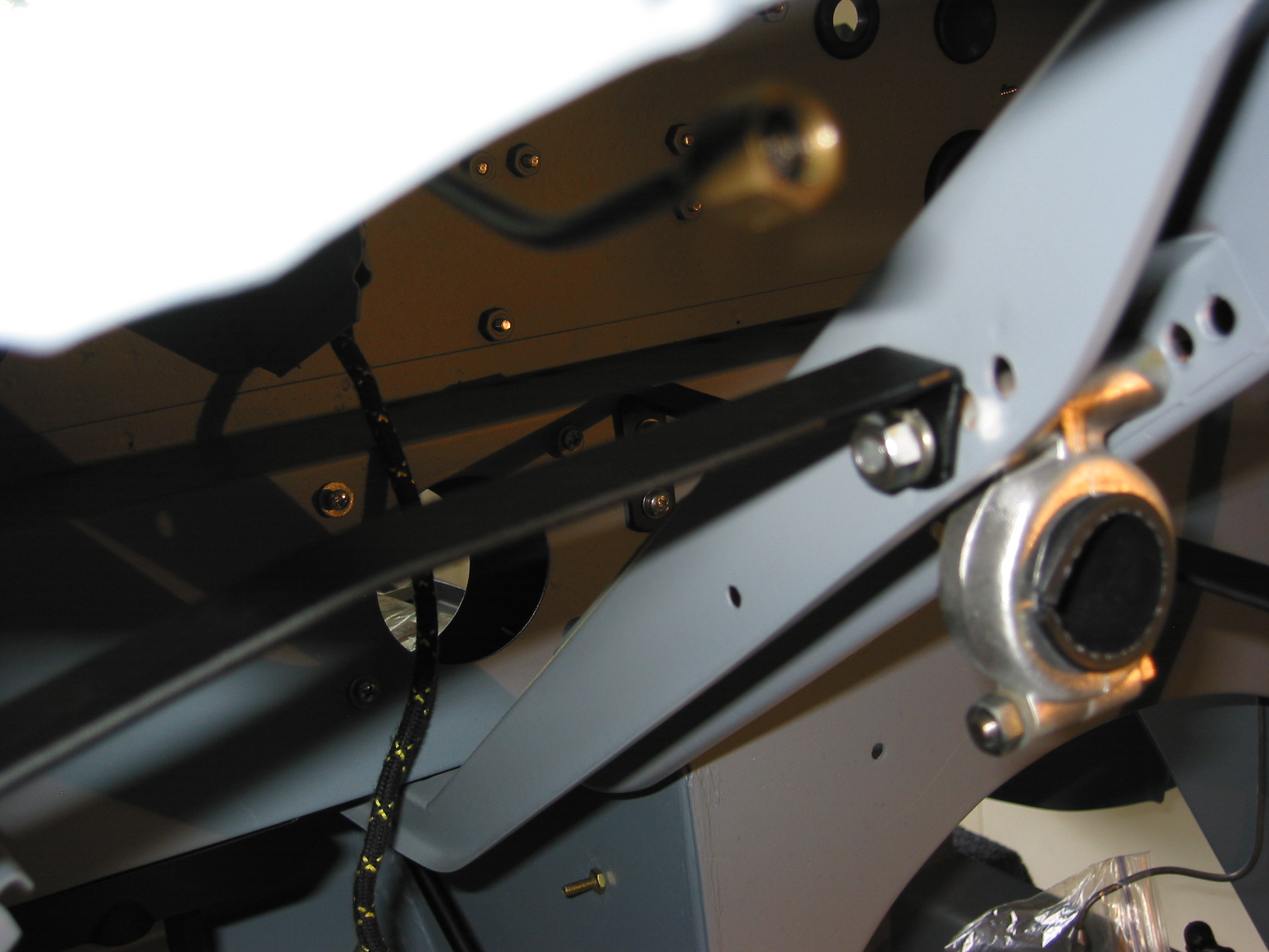
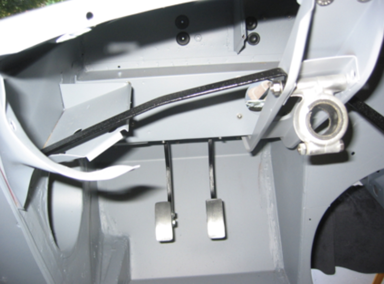
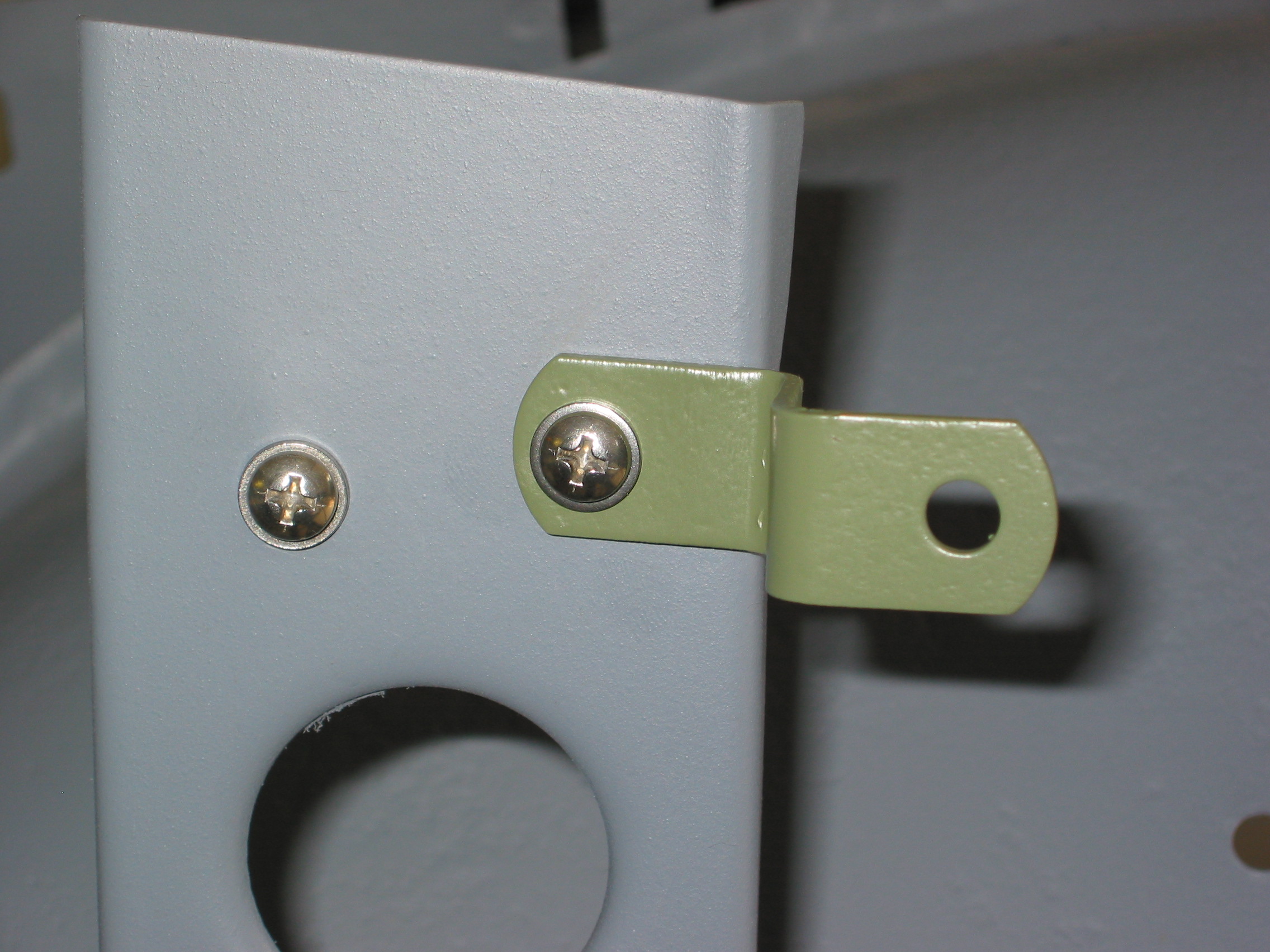
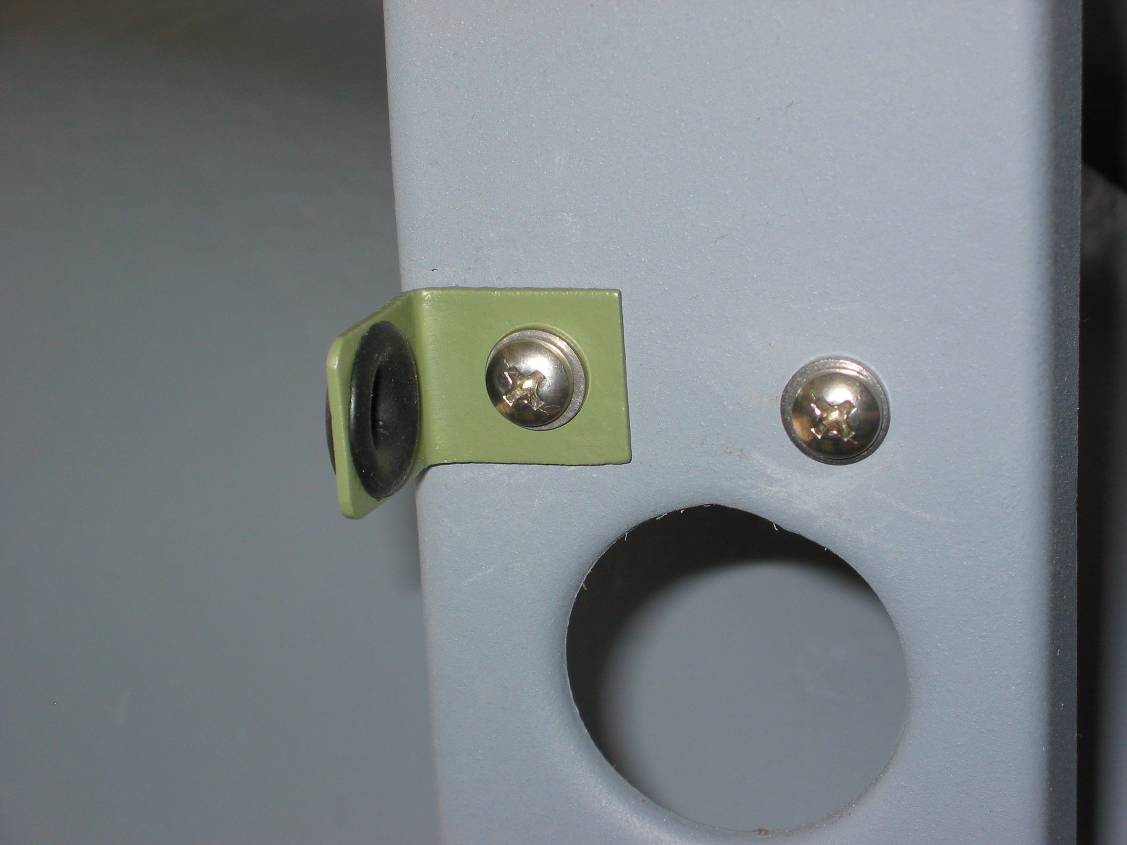
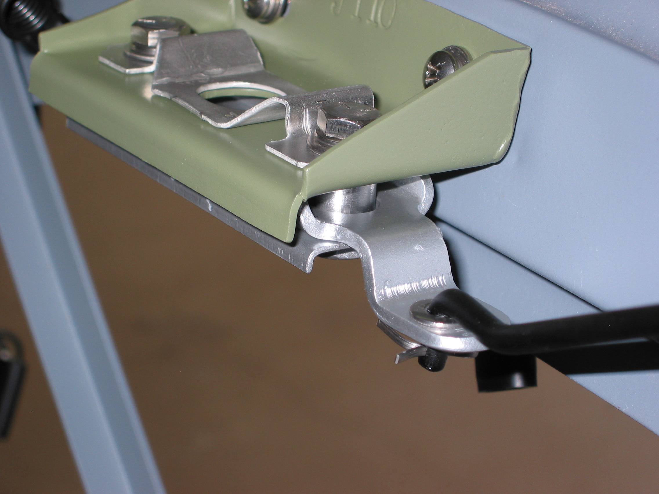
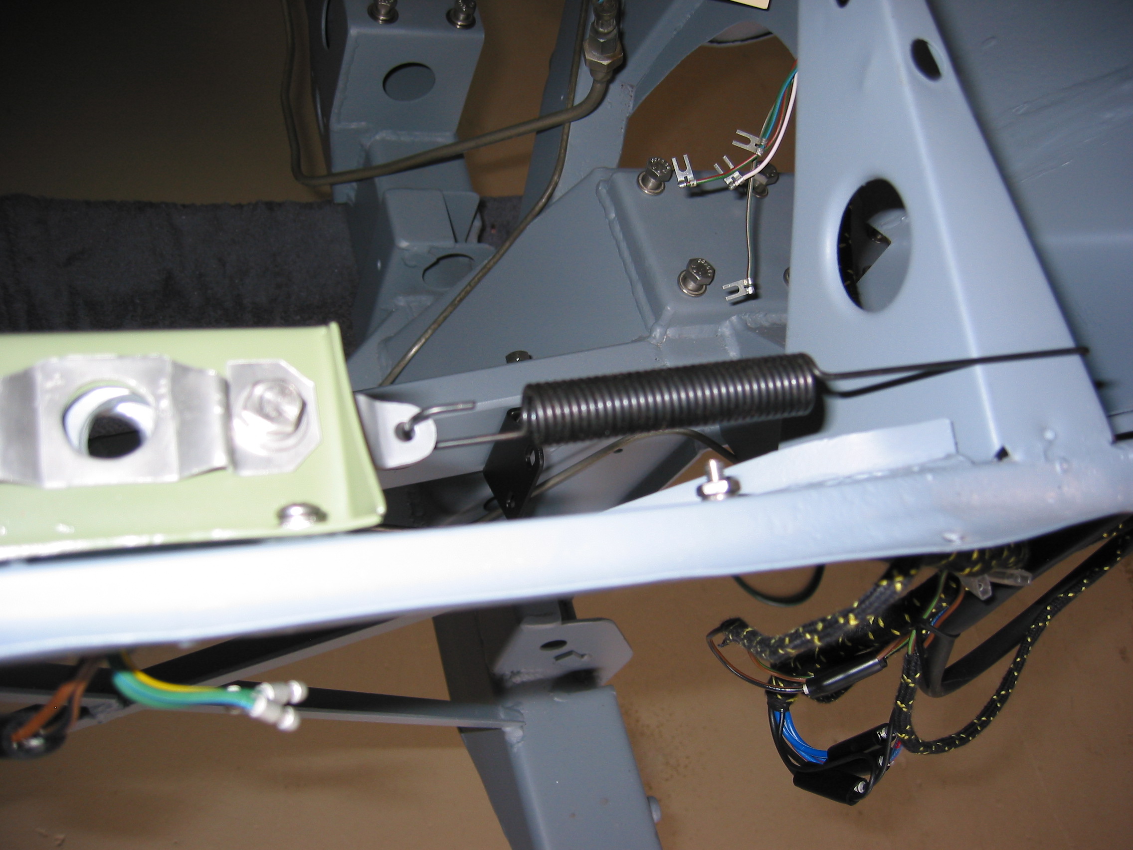
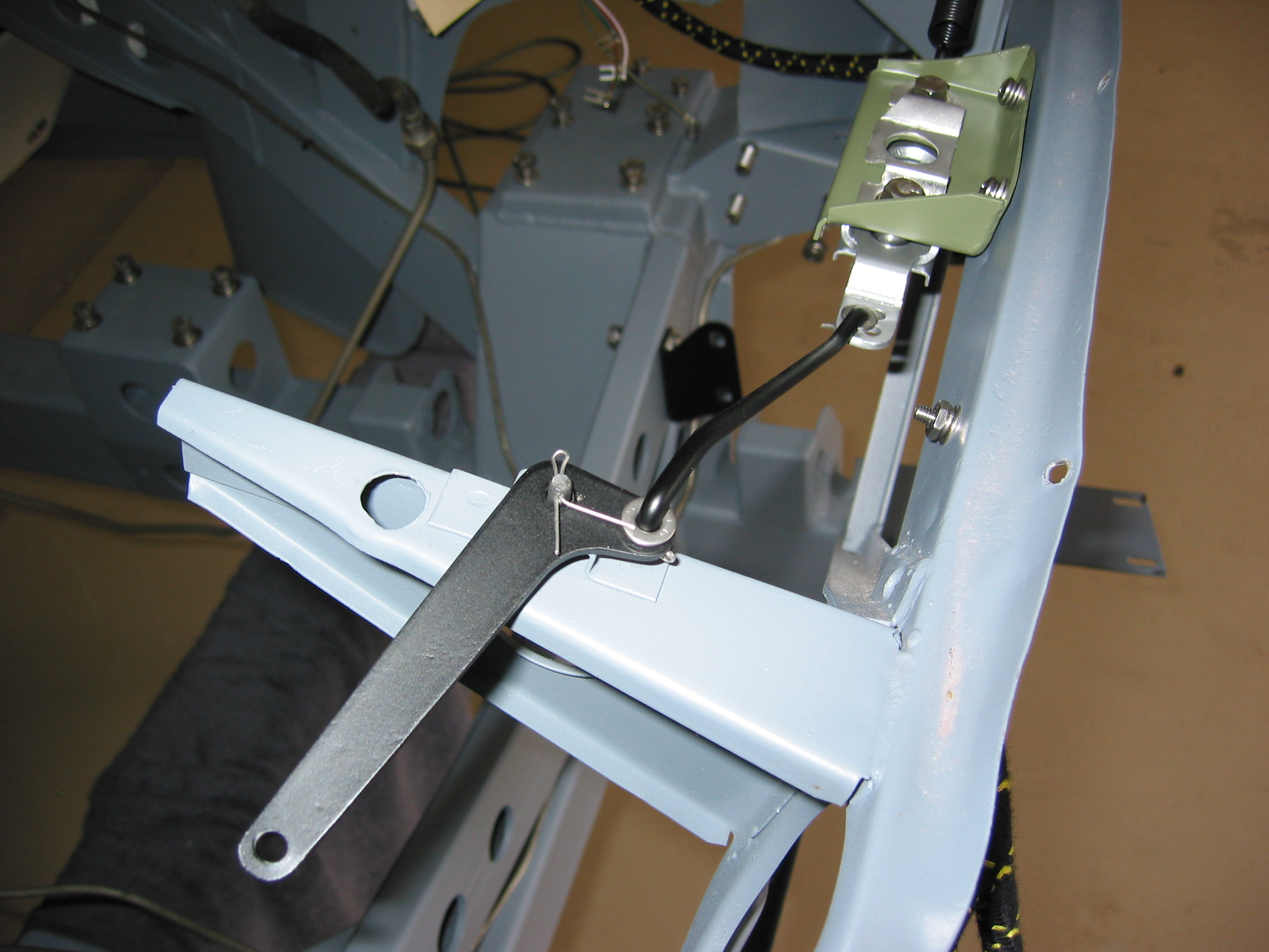
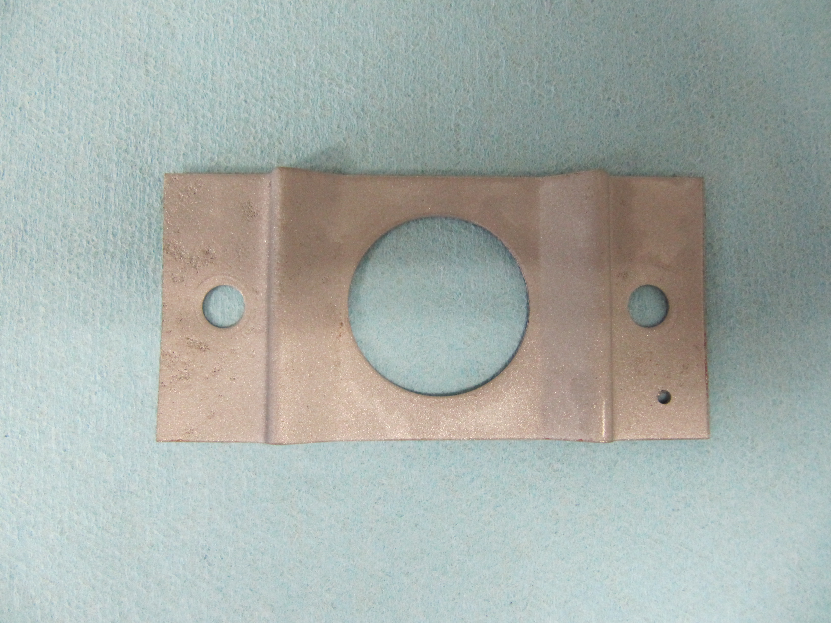
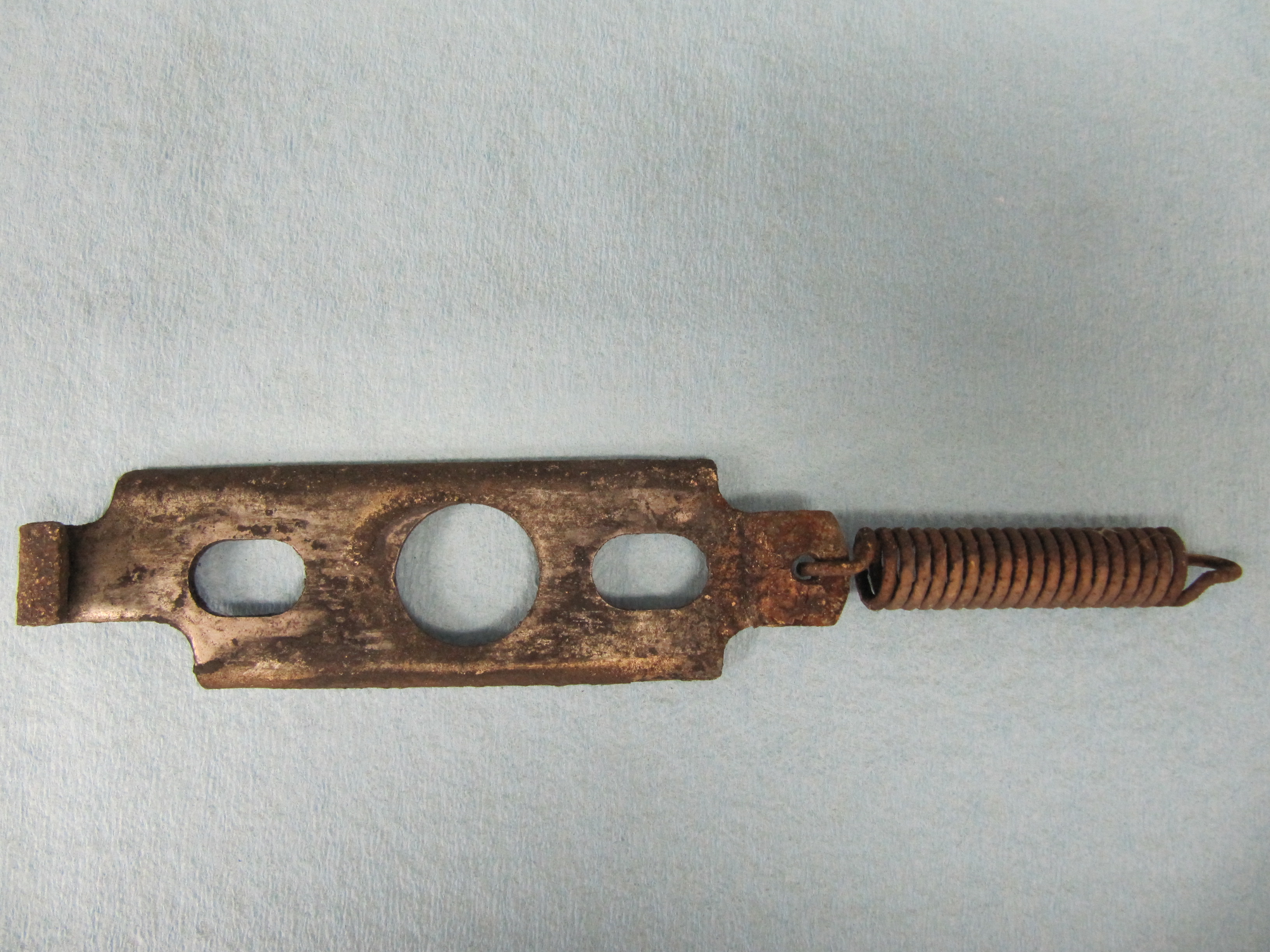
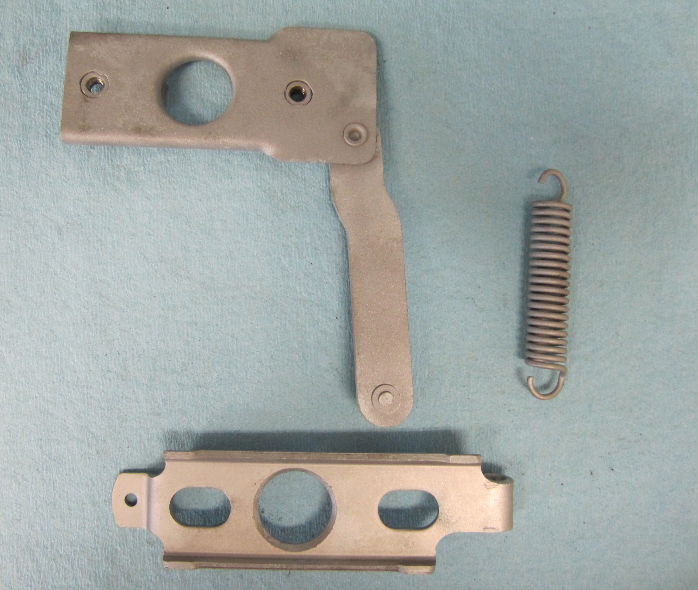
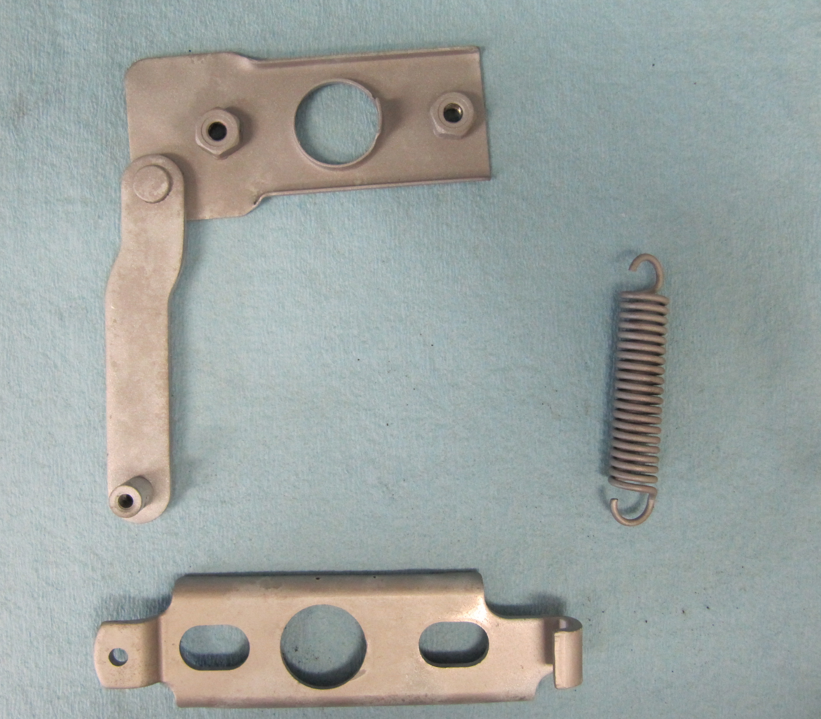
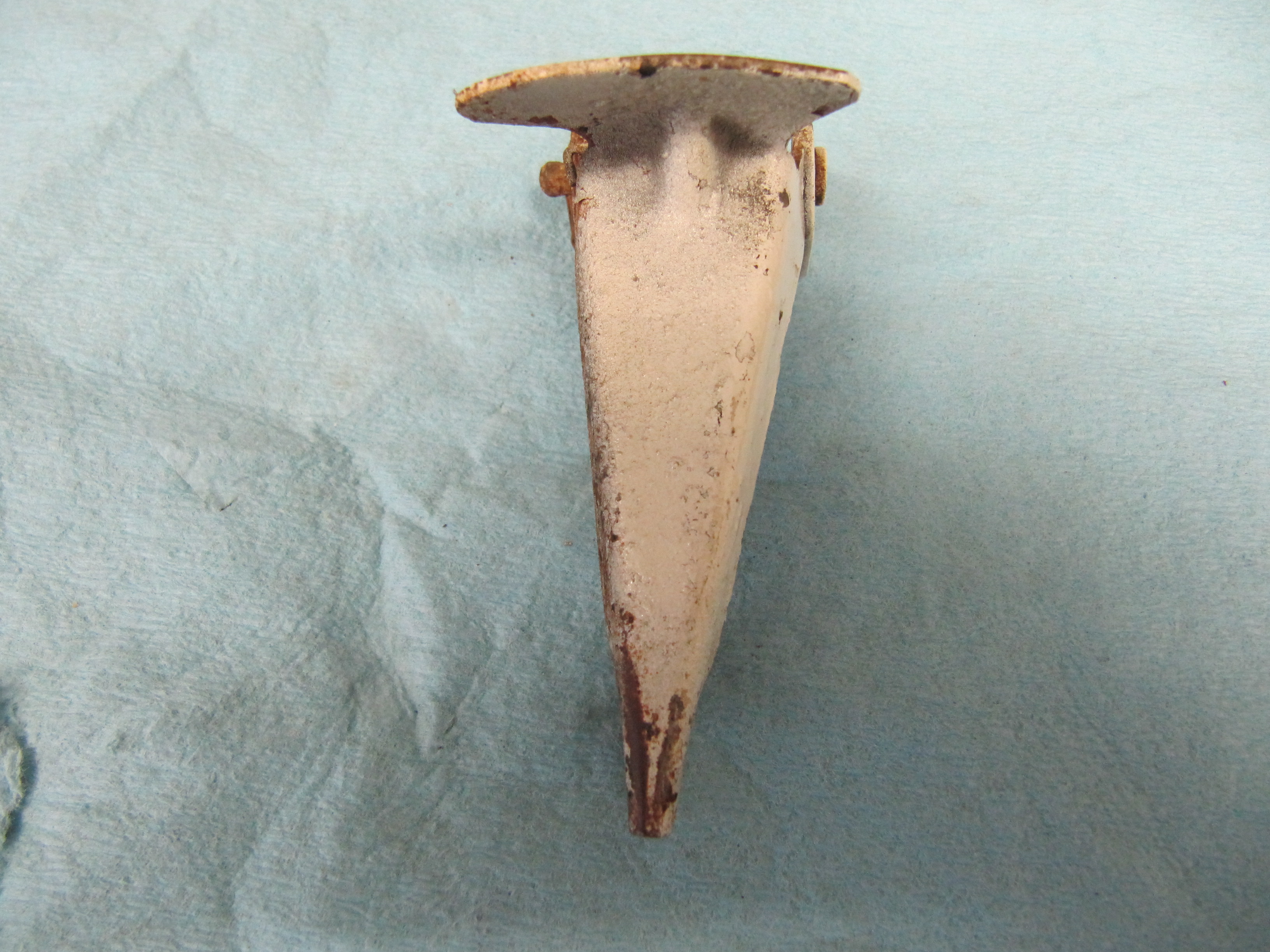
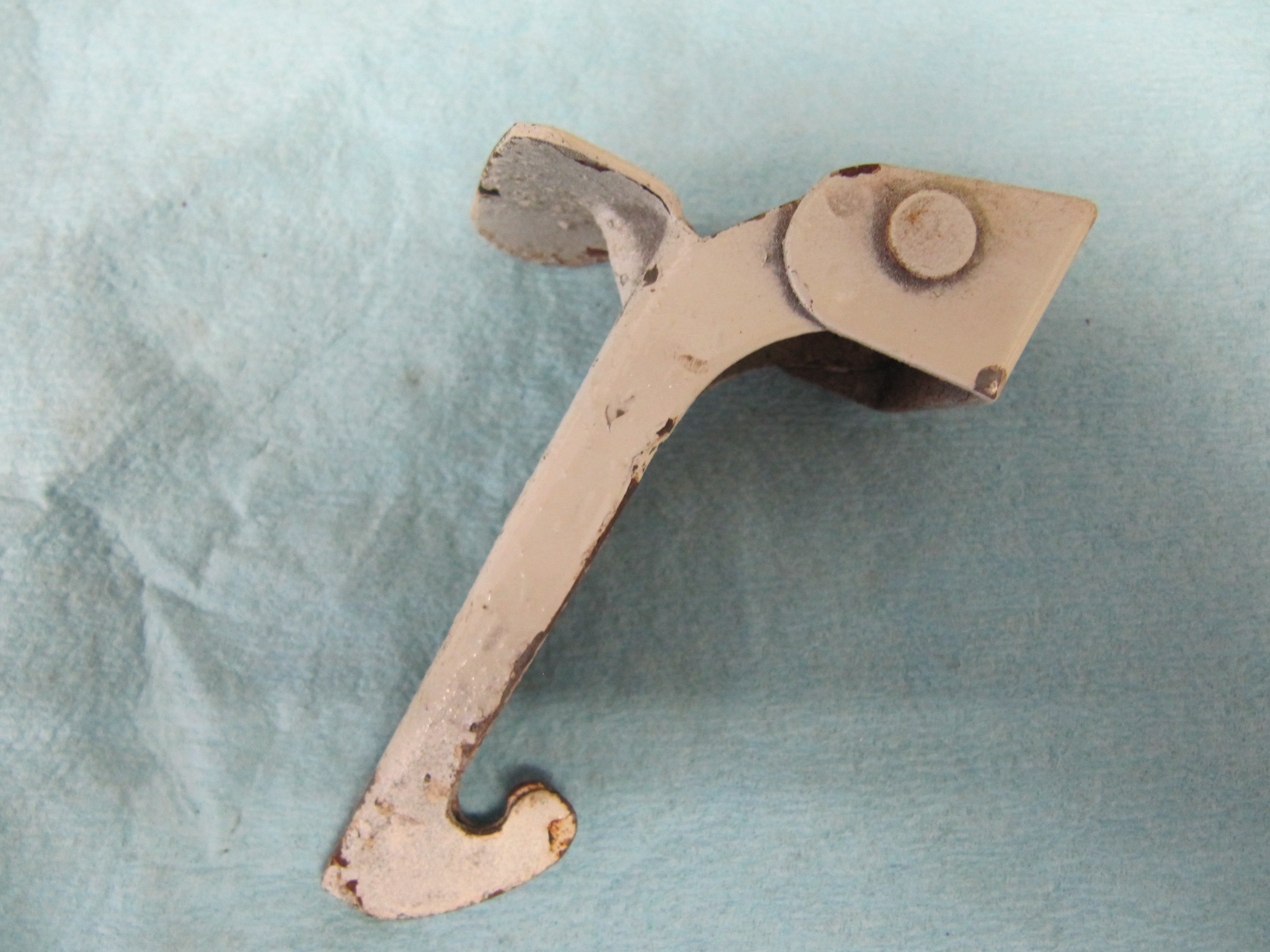
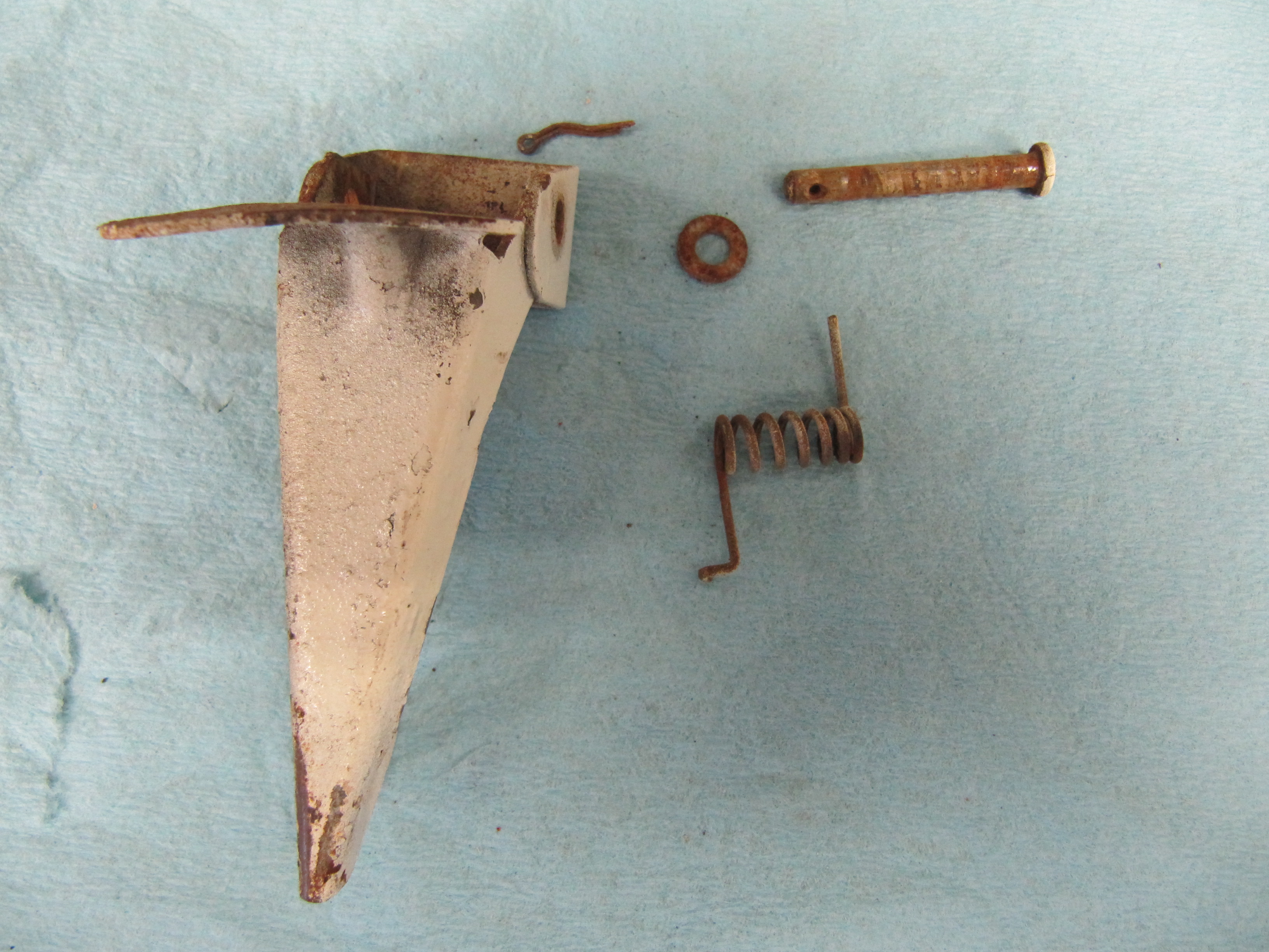
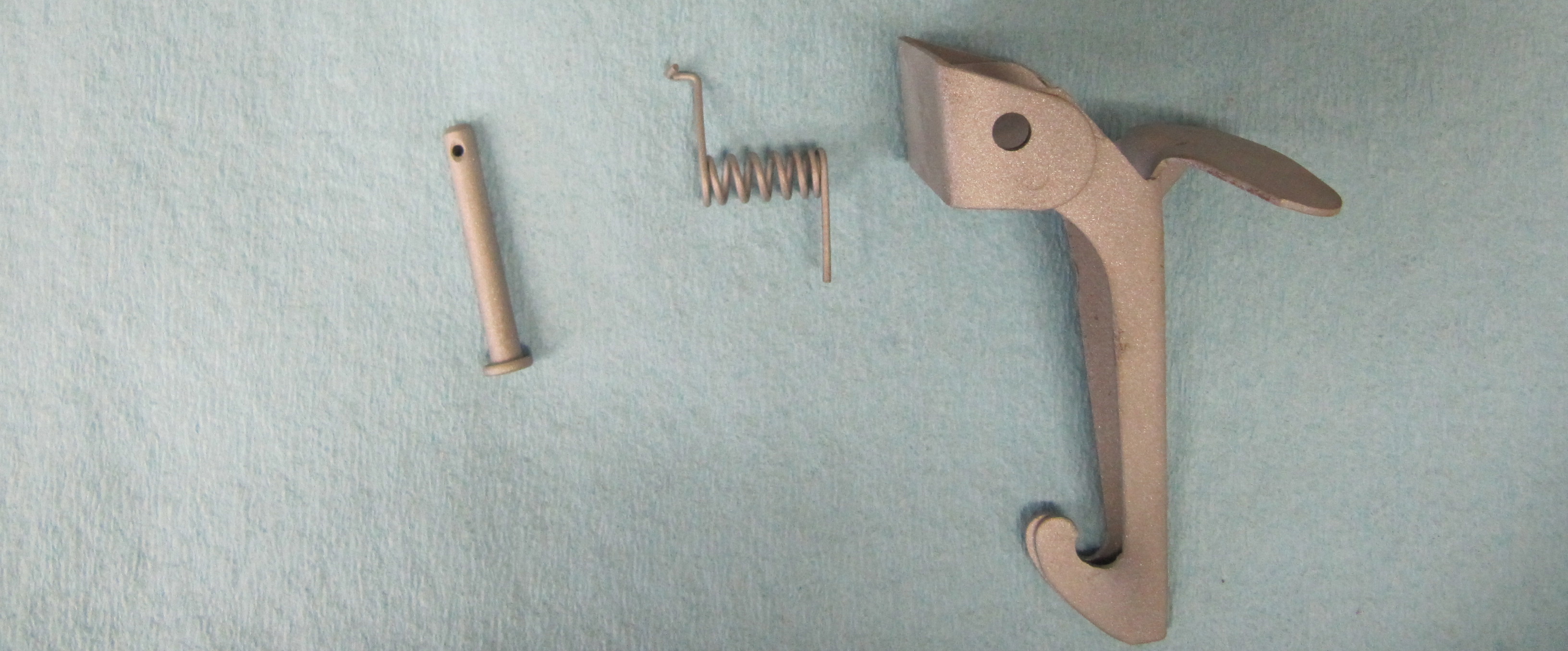
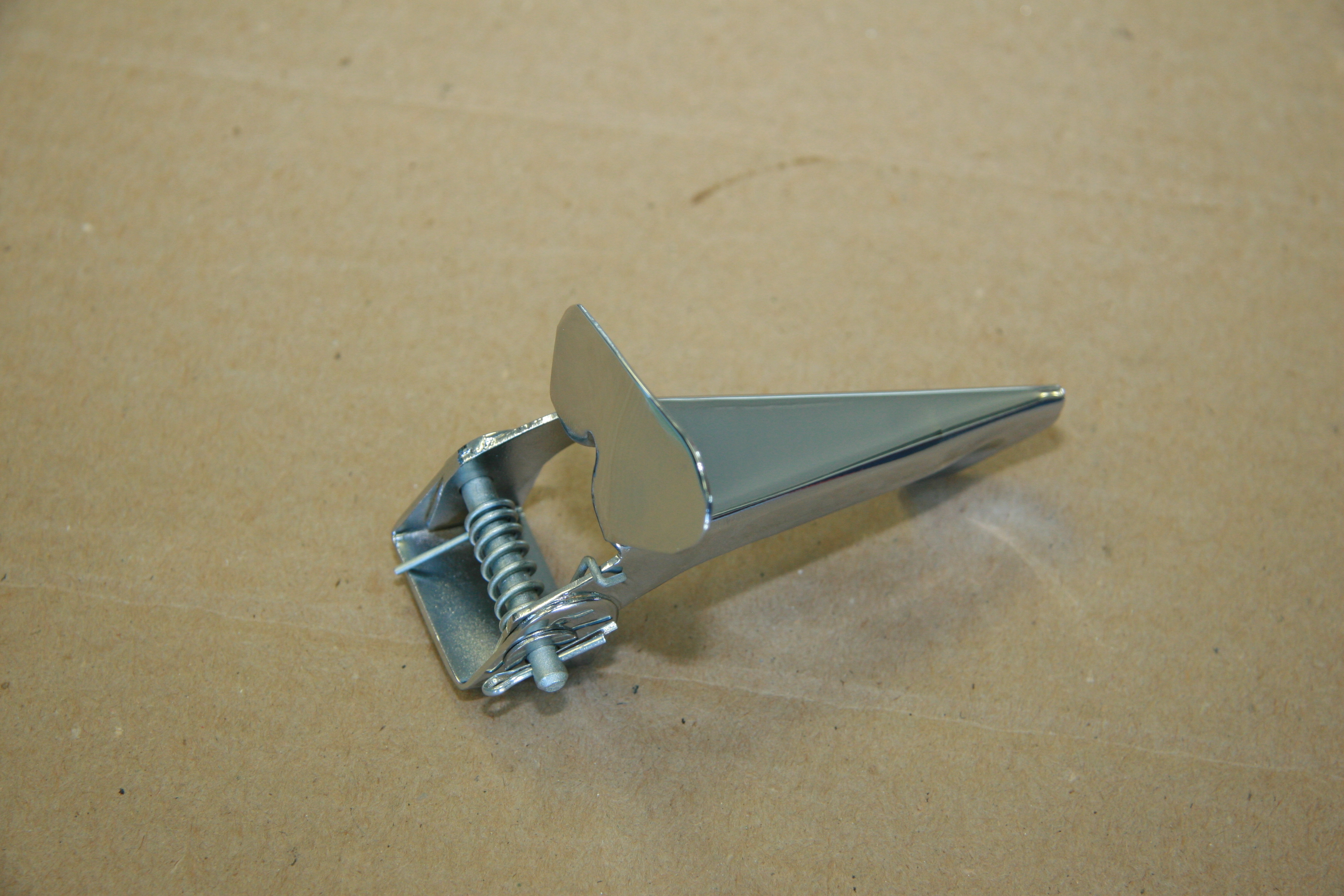
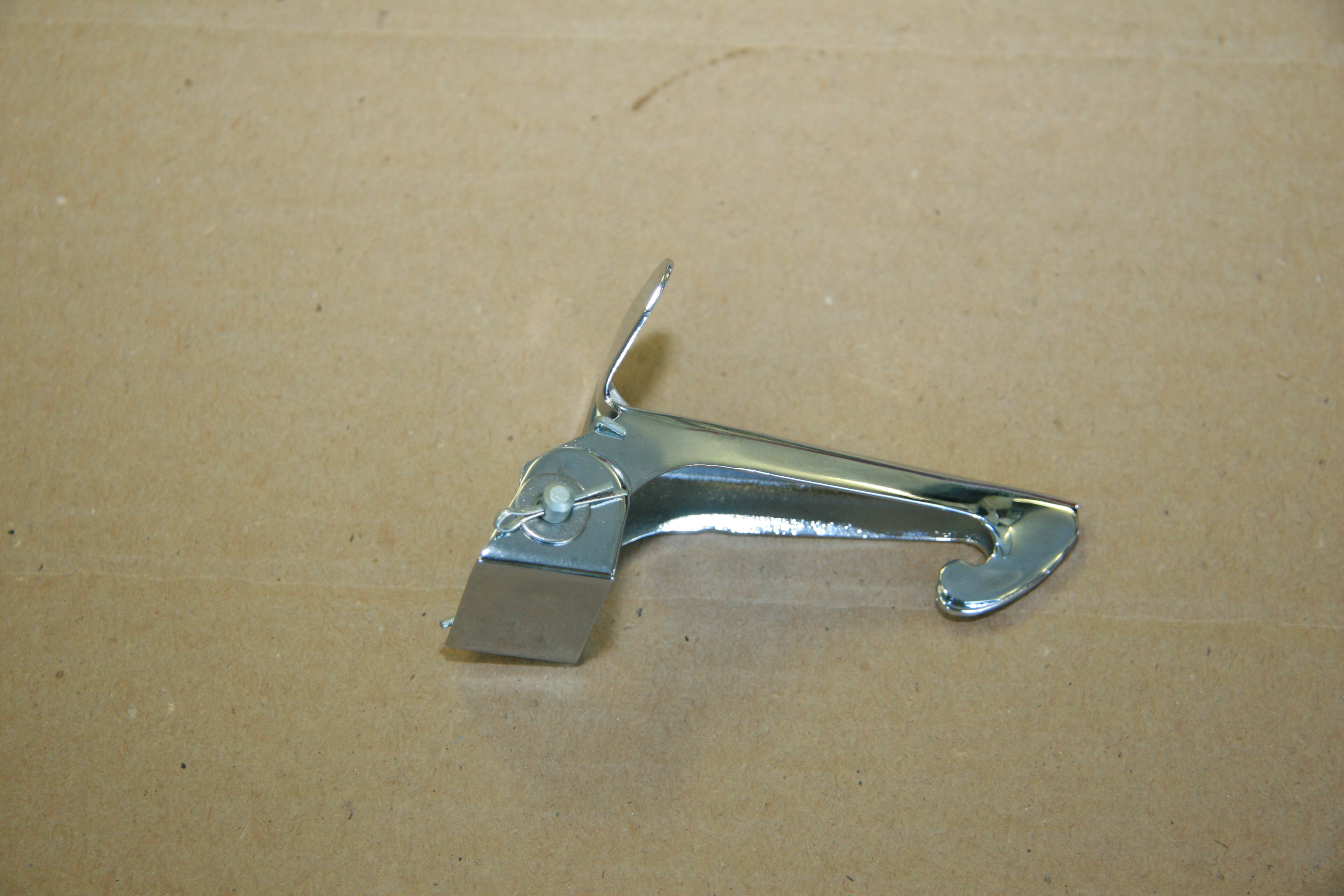
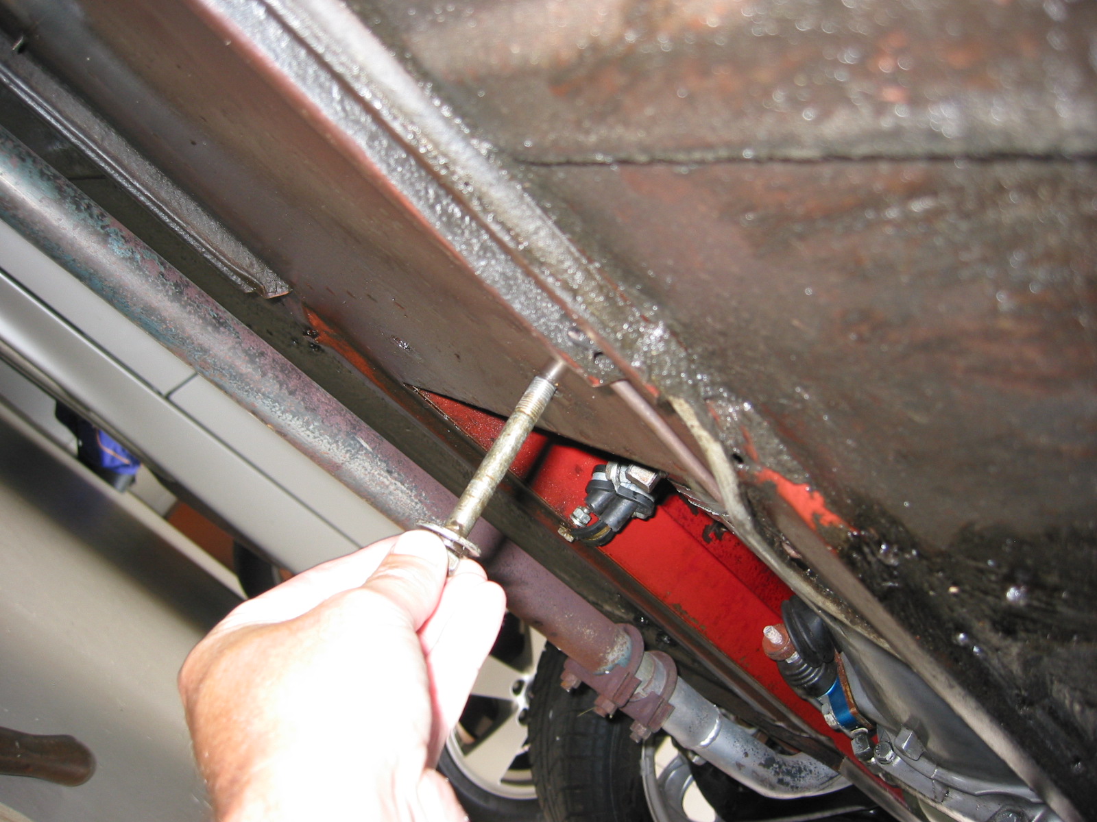
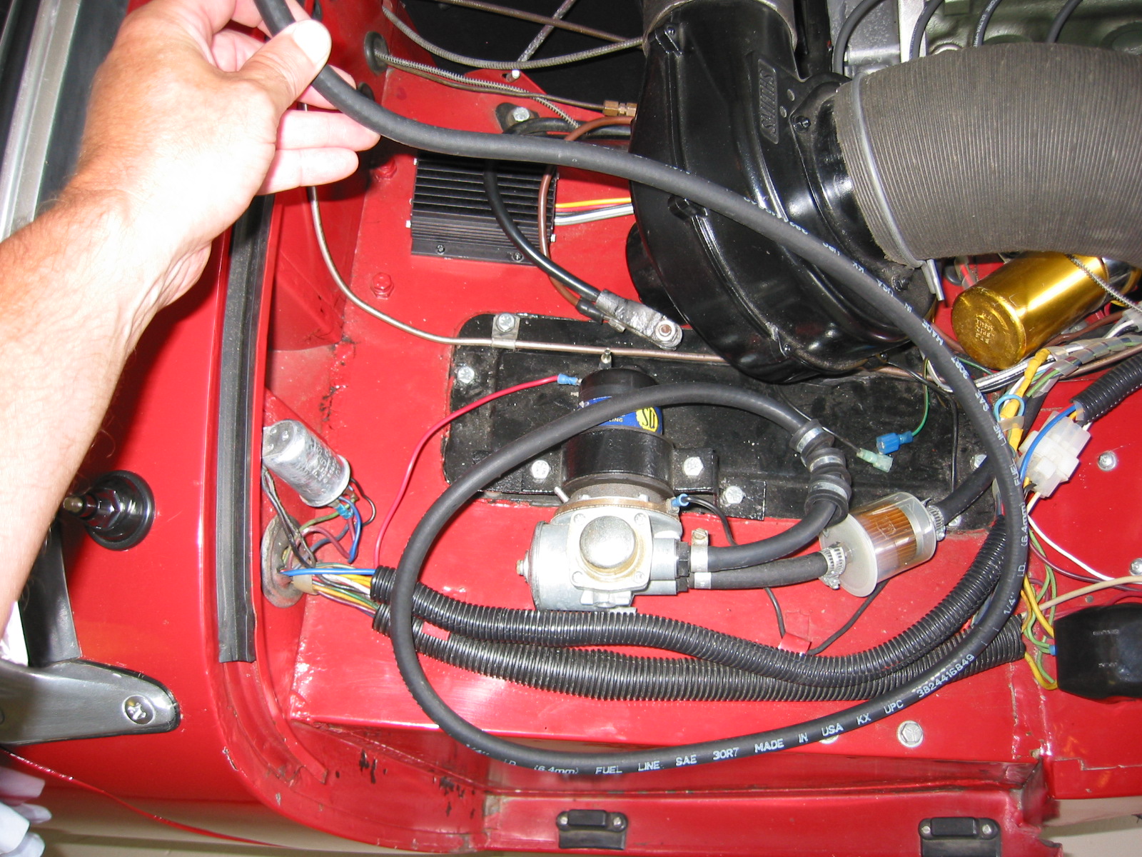
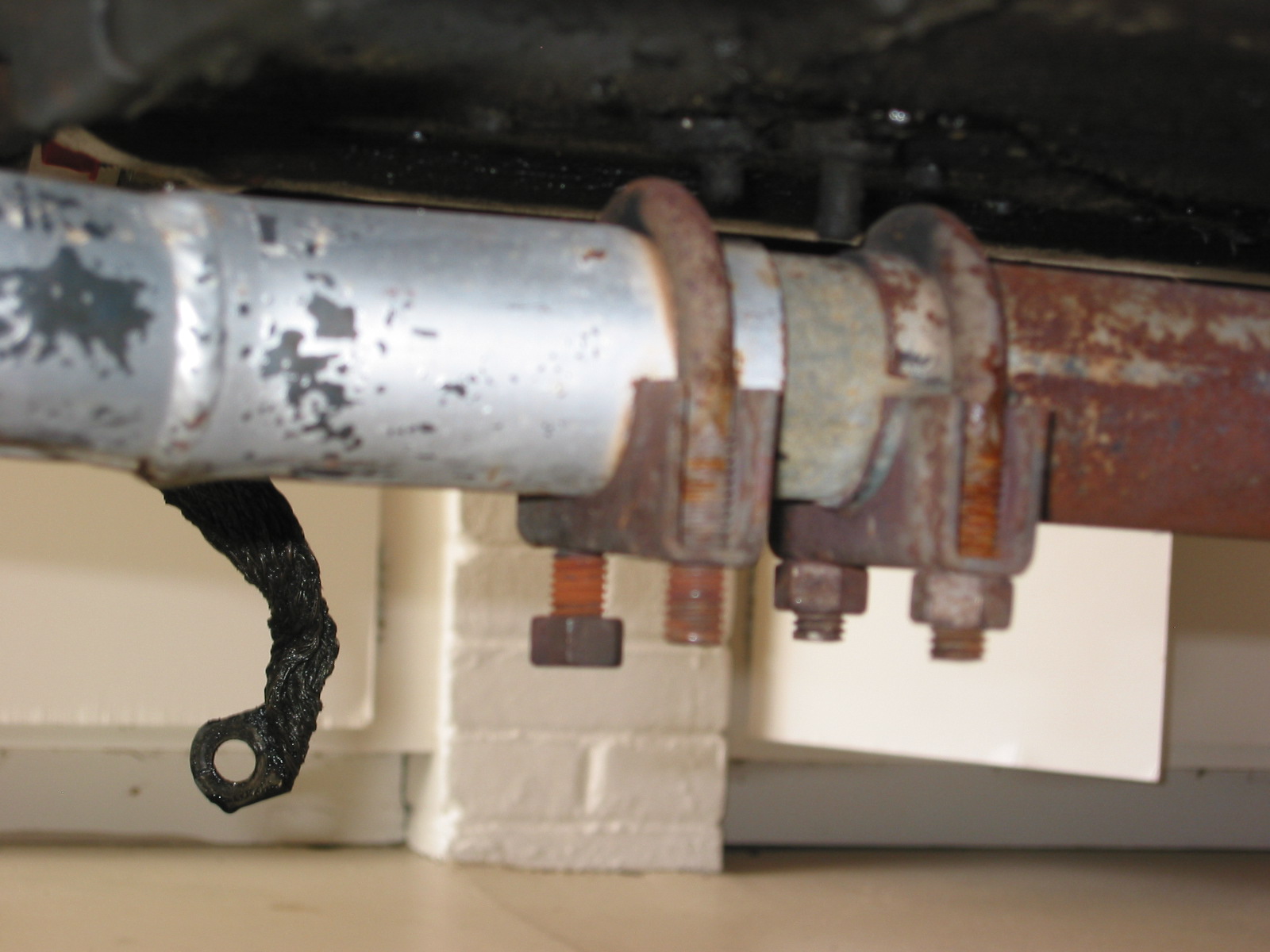
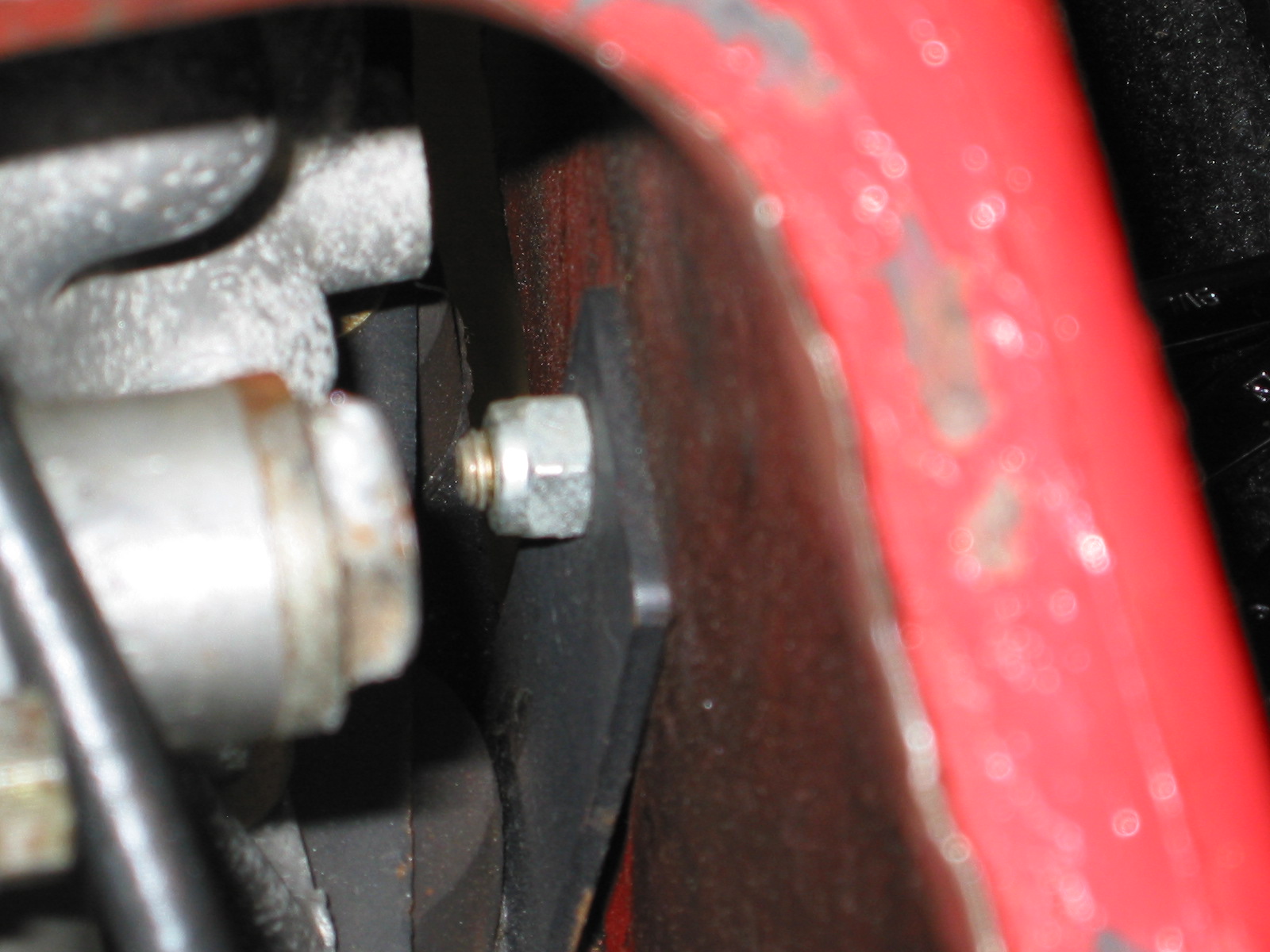
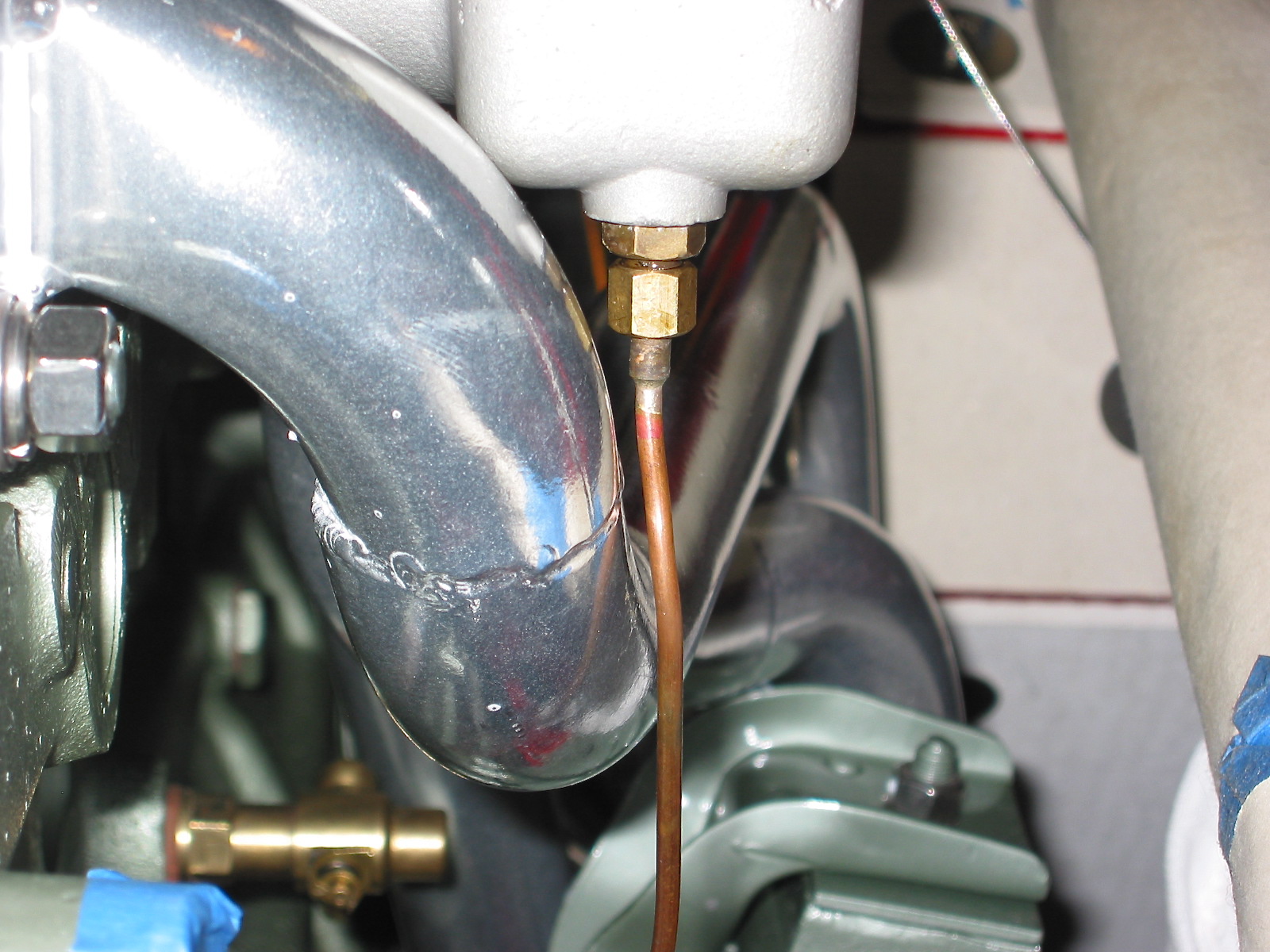
With the engine in place, it was now time to complete the assembly of the various engine components, but first I installed the clutch slave cylinder with the push rod provided in the Smitty conversion kit. It went in without any problem and lined up perfectly. The clutch pedal seemed to work smoothly. The bleeder extension pipe was attached to the bracket I made to support the pipe. Bleeding the slave cylinder will now be a much easier job. Thanks again to Mr. Finespanner – Doug Reid.
Slave cylinder bleeder extension 2
Just to fill the holes and to prevent anything from dropping in unexpectedly I went ahead and loosely fit the NGK Spark Plugs BP6ES, stock number 7333.
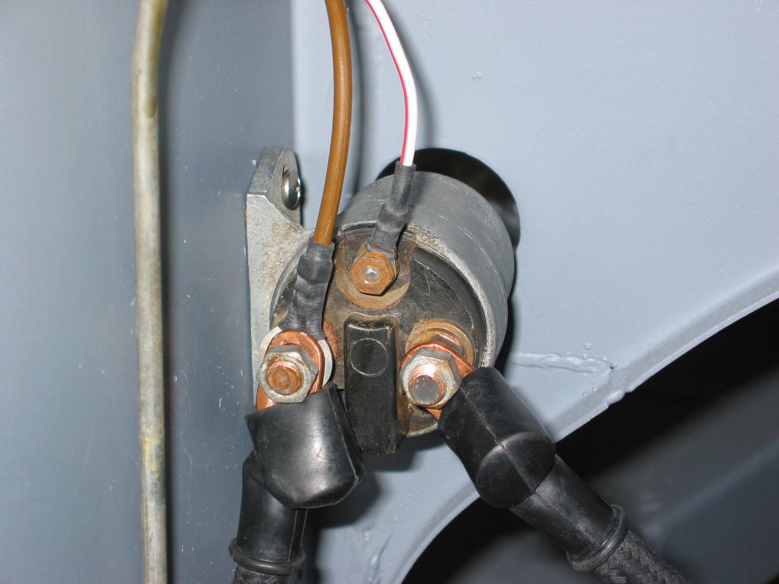
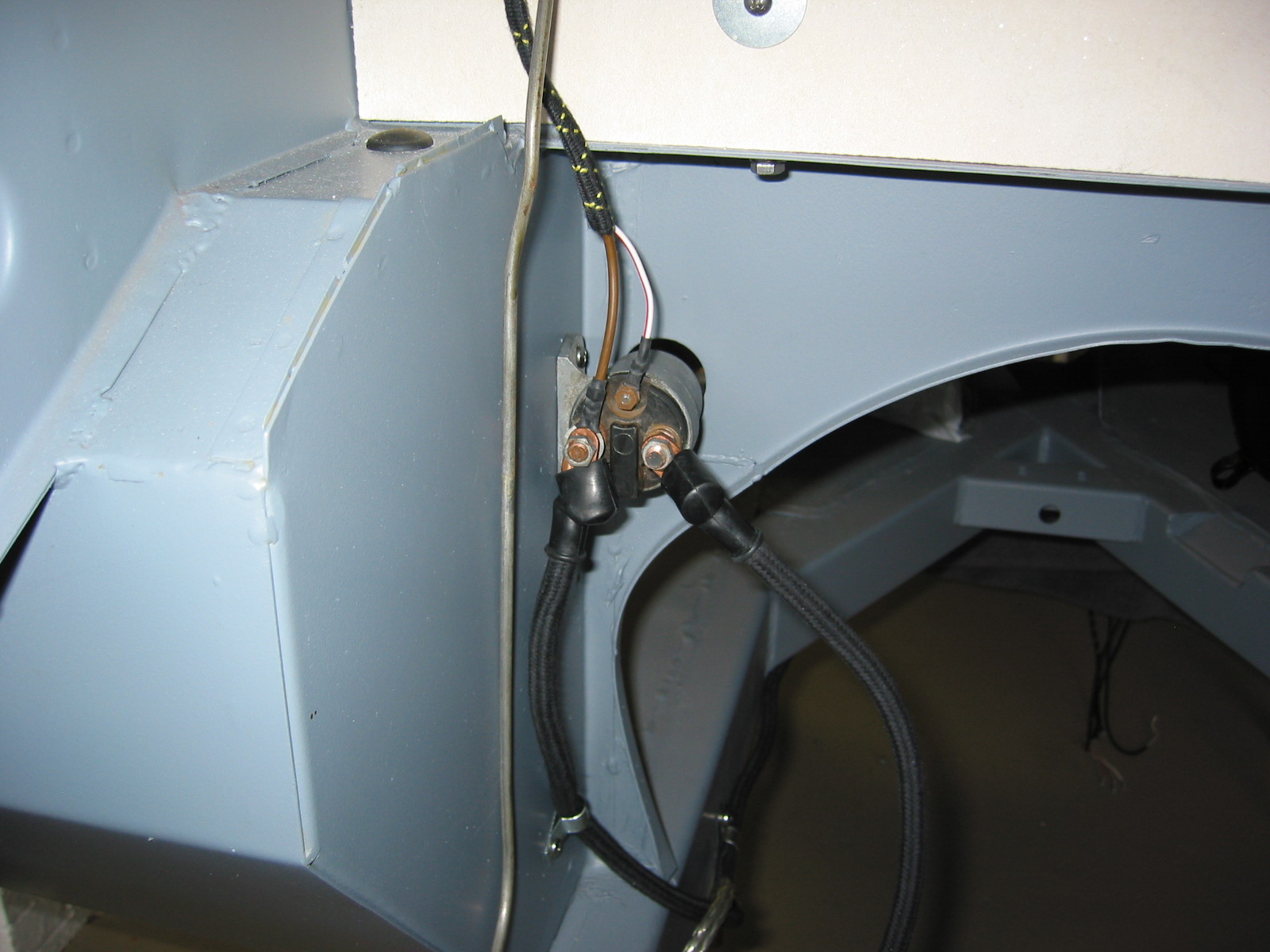
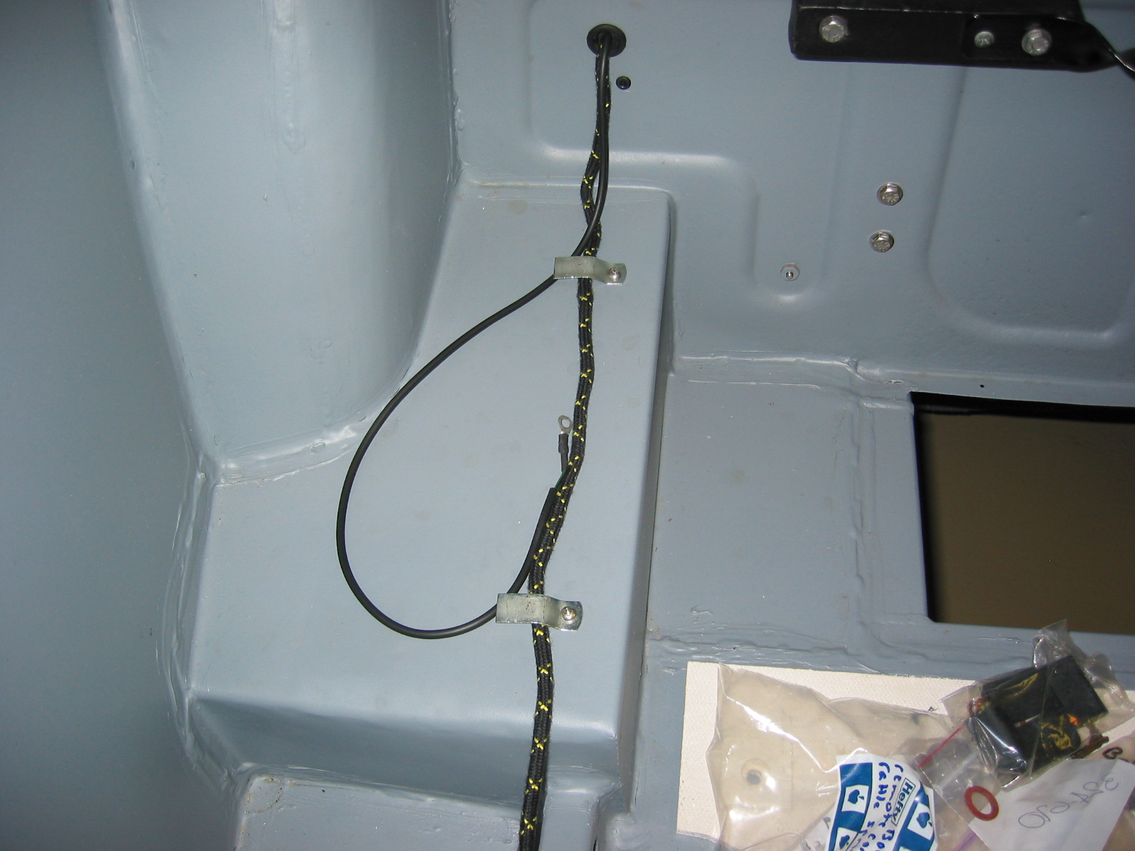
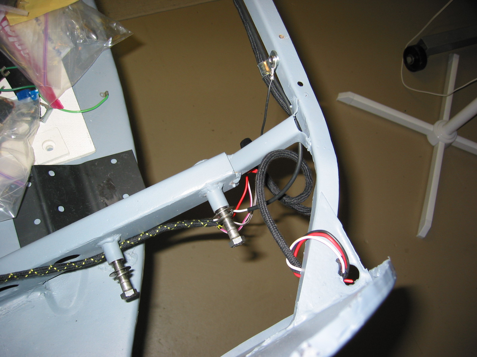
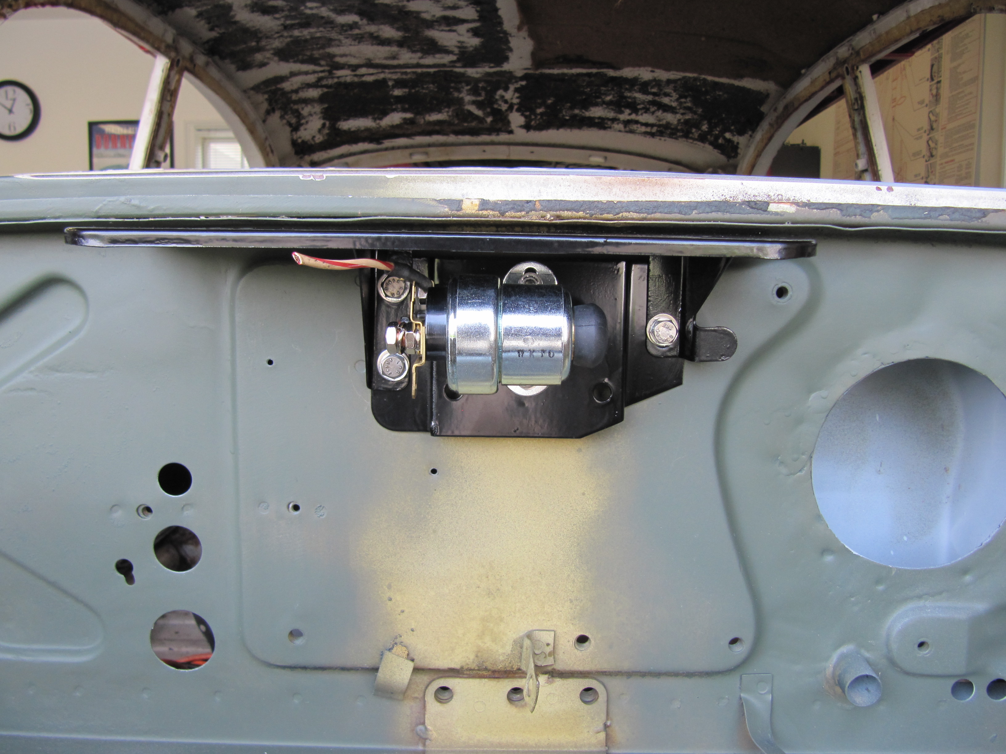
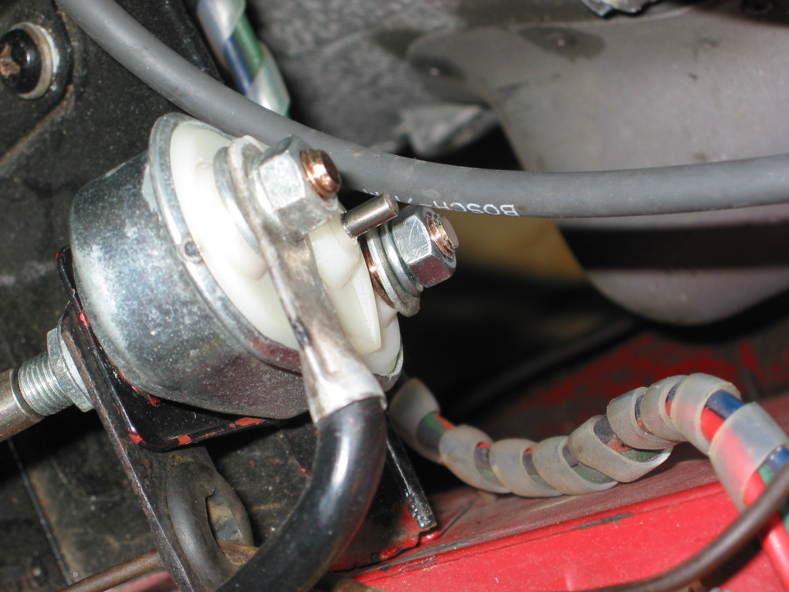
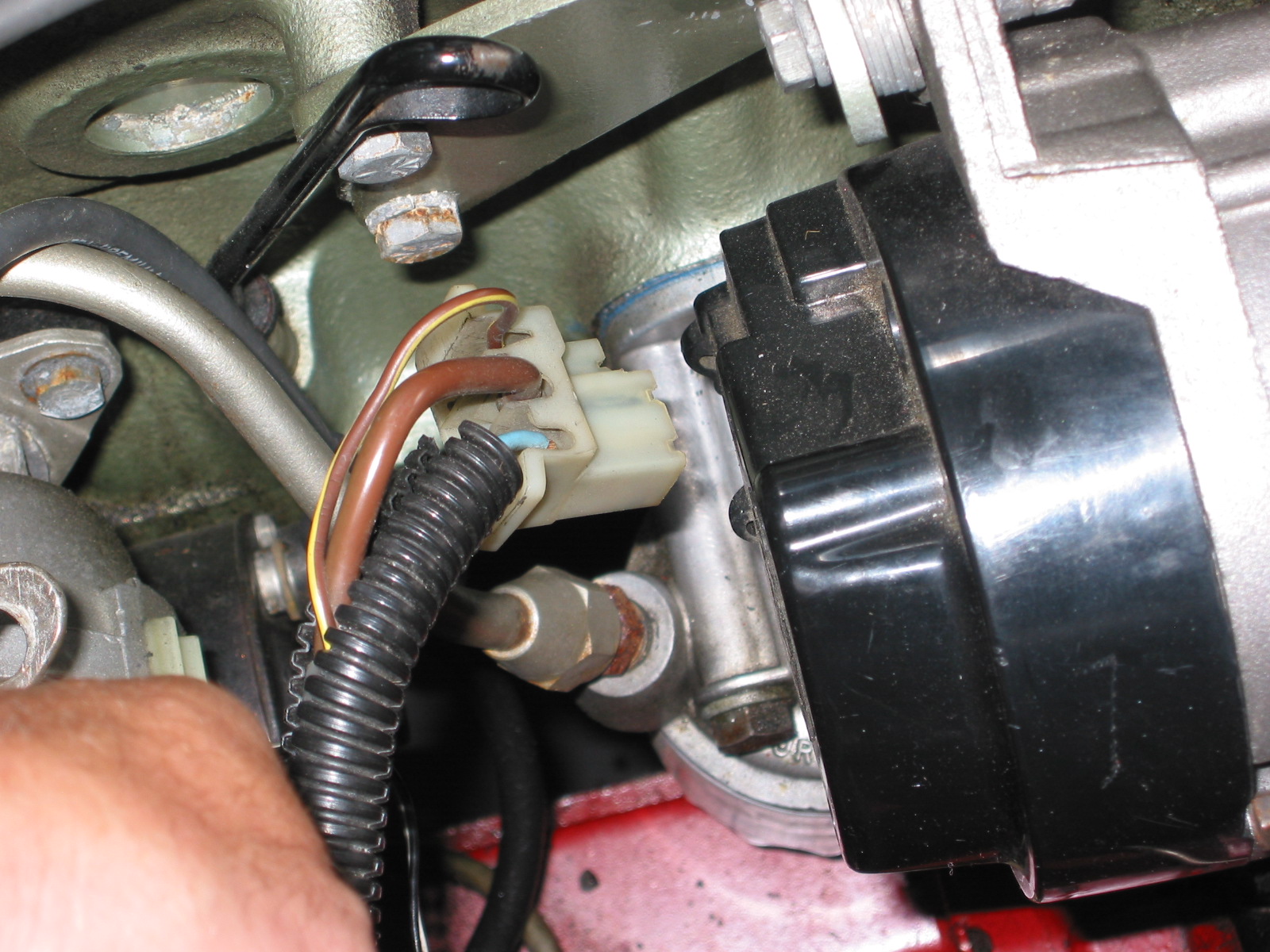
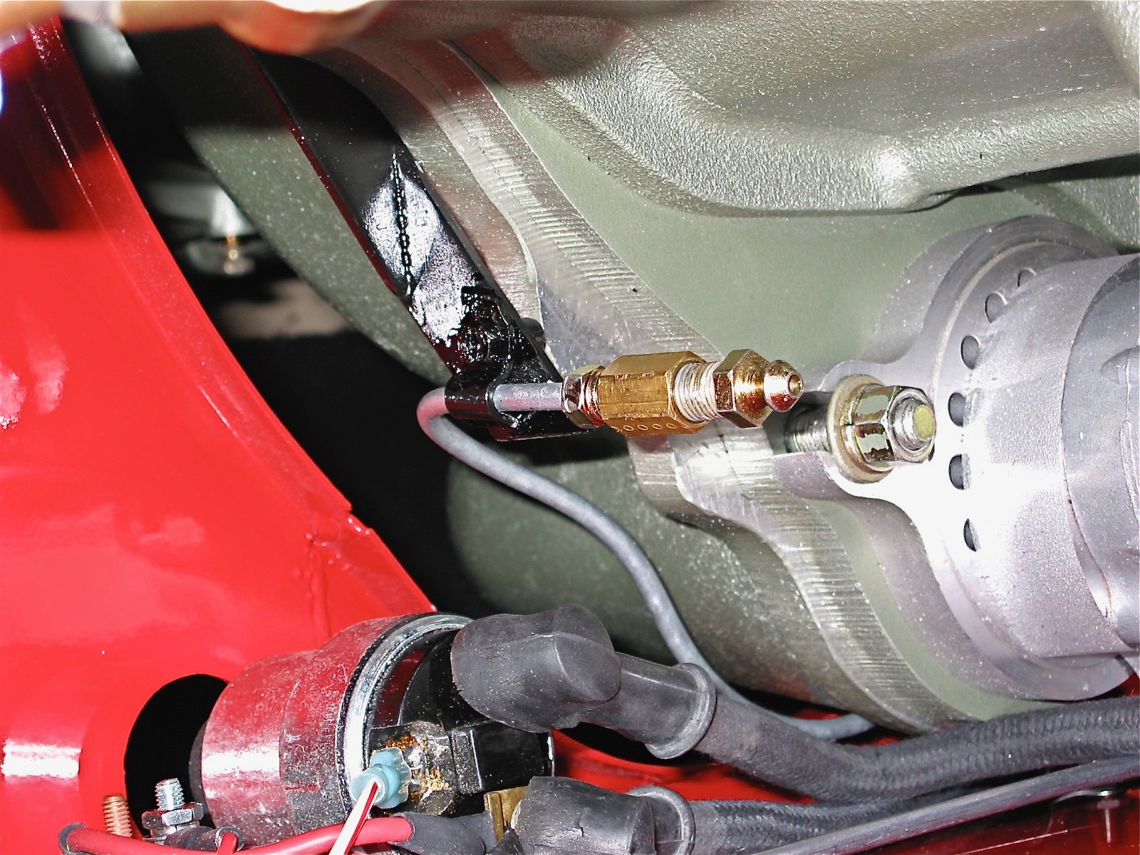
To make installation a little easier I attached the gear reduction starter to the engine prior to installation in the car, and it was now time to hook up the wiring. I shortened the heavy duty starter cable that connects the solenoid and the starter and secured it to the starter with rubber insulation boots attached. Since my intention is to still rely on the original starting configuration, that is, using the external solenoid, I connected the small wire on the starter to the terminal post also used to connect the cable from the solenoid.

Starter
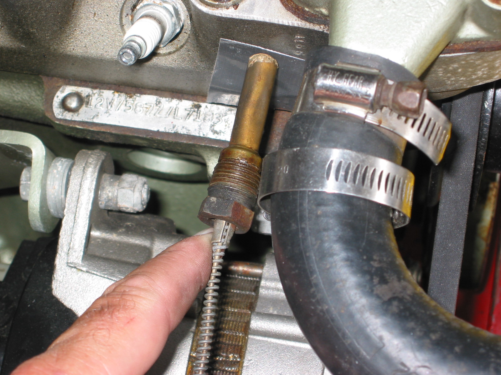
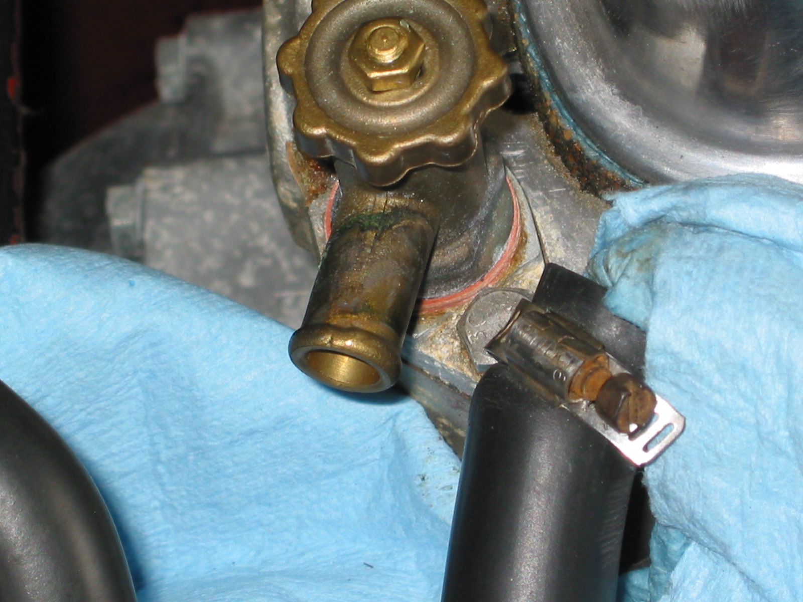
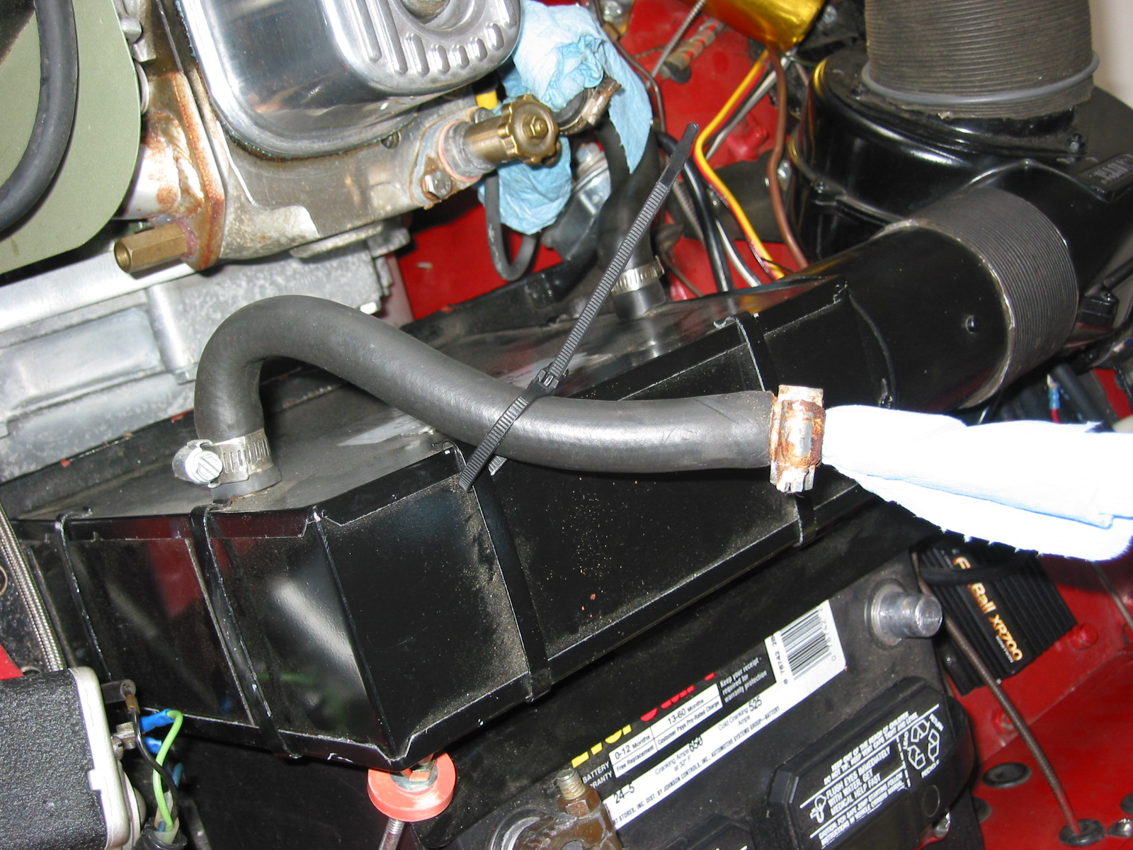
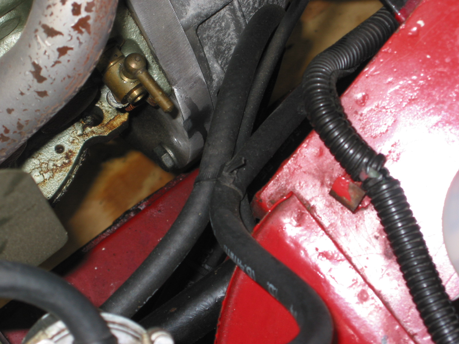
The installation of the breather pipe and hoses was next on my list. Since I will be taking off the rocker cover for valve gap adjustment once the engine is started, I left the clamp to the “T” connection on the cover loose. The inlet heater hose from the heater to the heater control tap on the motor. While in that location I went ahead and connected the tachometer cable to the tach drive housing.
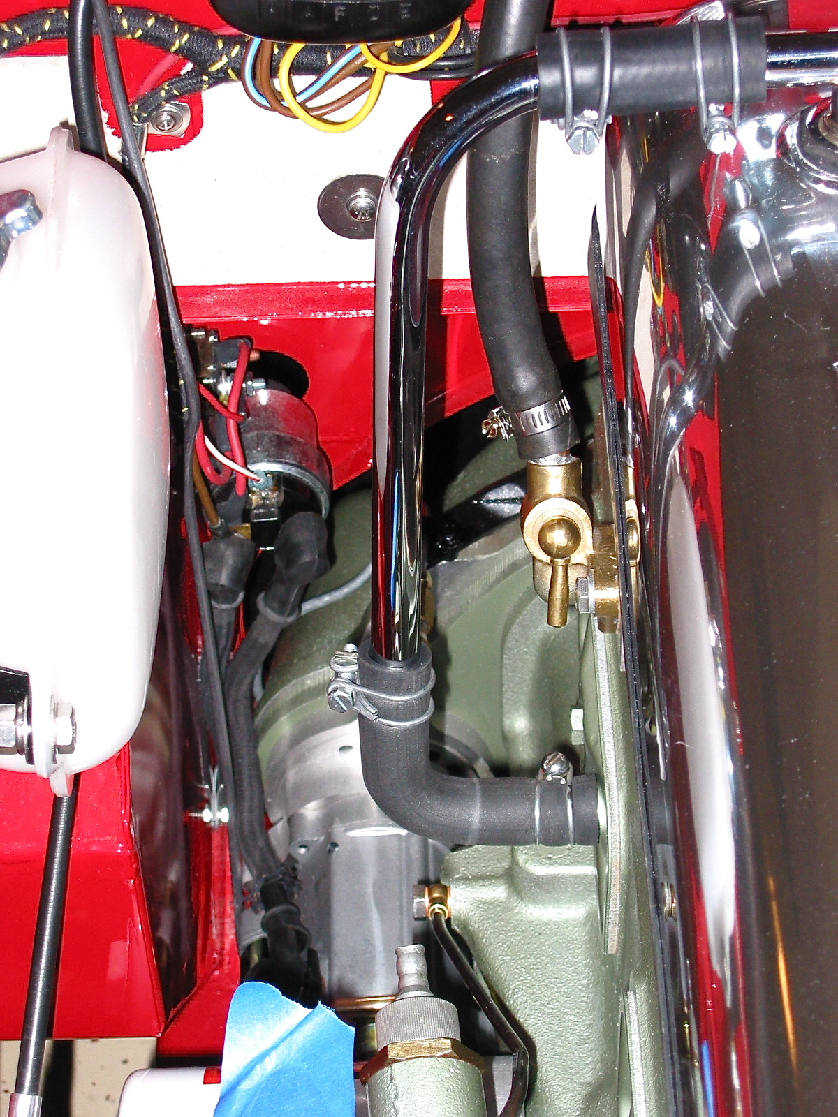
Breather Pipe 2
Tach Cable to Drive Gear
Others have suggested the addition of a PCV valve connecting the breather “T” to the intake manifold to assist in minimizing oil pressure leaks. I bought a little kit from the British Car Specialists that included the valve, rubber piping and a connector for the intake manifold. It will be interesting to see if it does aid in respiration.
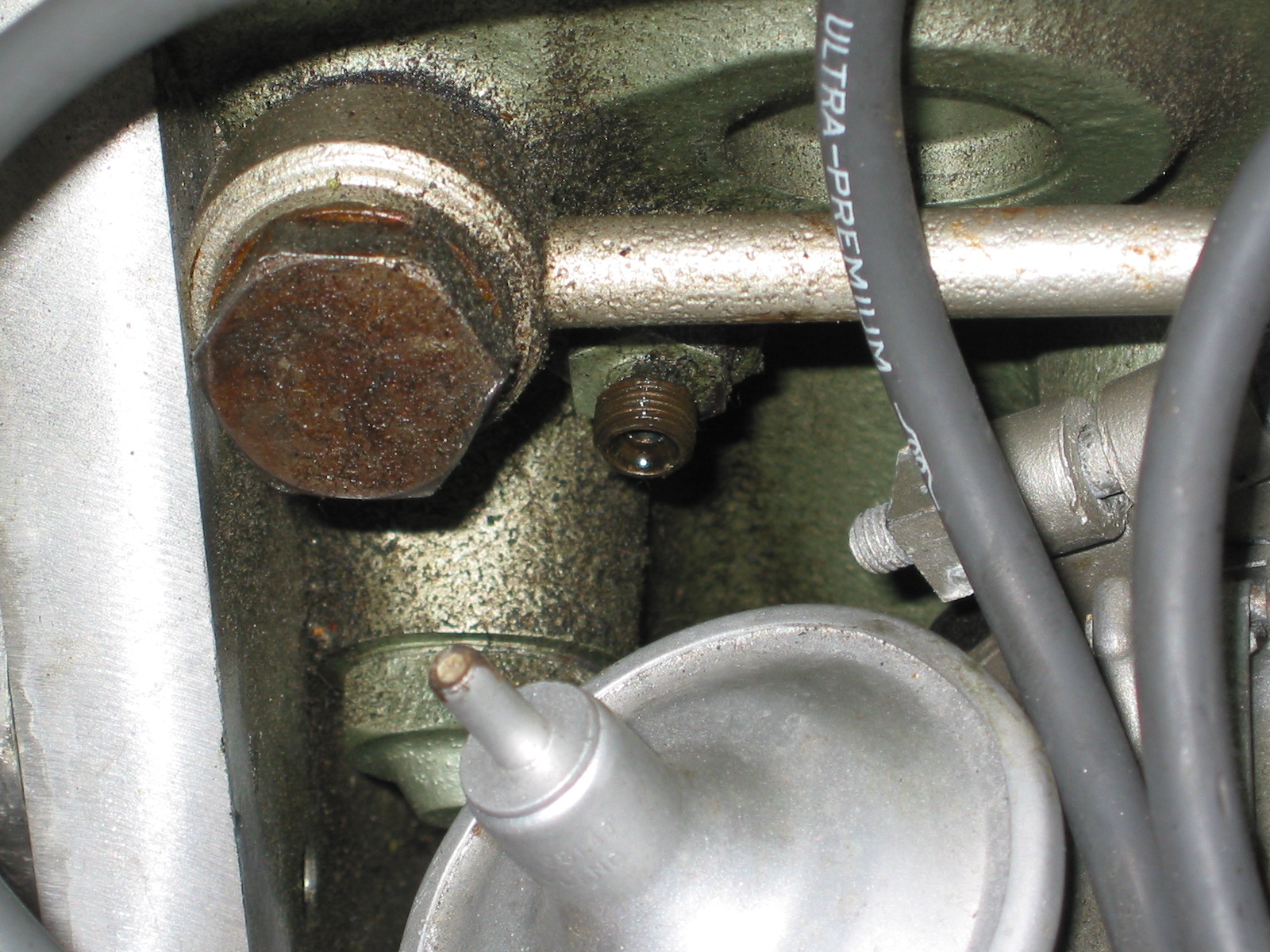
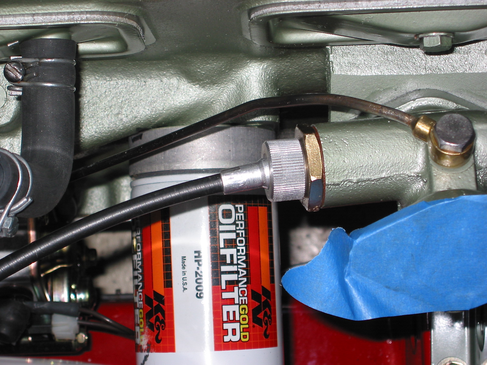
The oil gauge flexible hose was connected next. It connects to a fitting on the block and to the steel oil line that connects to the back of the oil pressure/water temperature gauge.

Oil Pressure Line
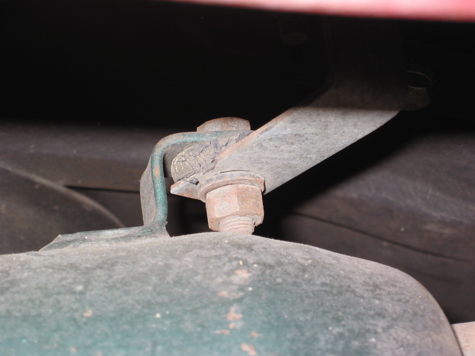
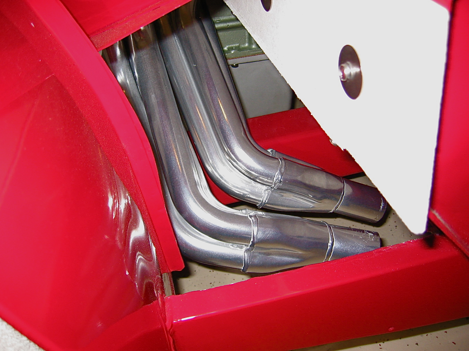
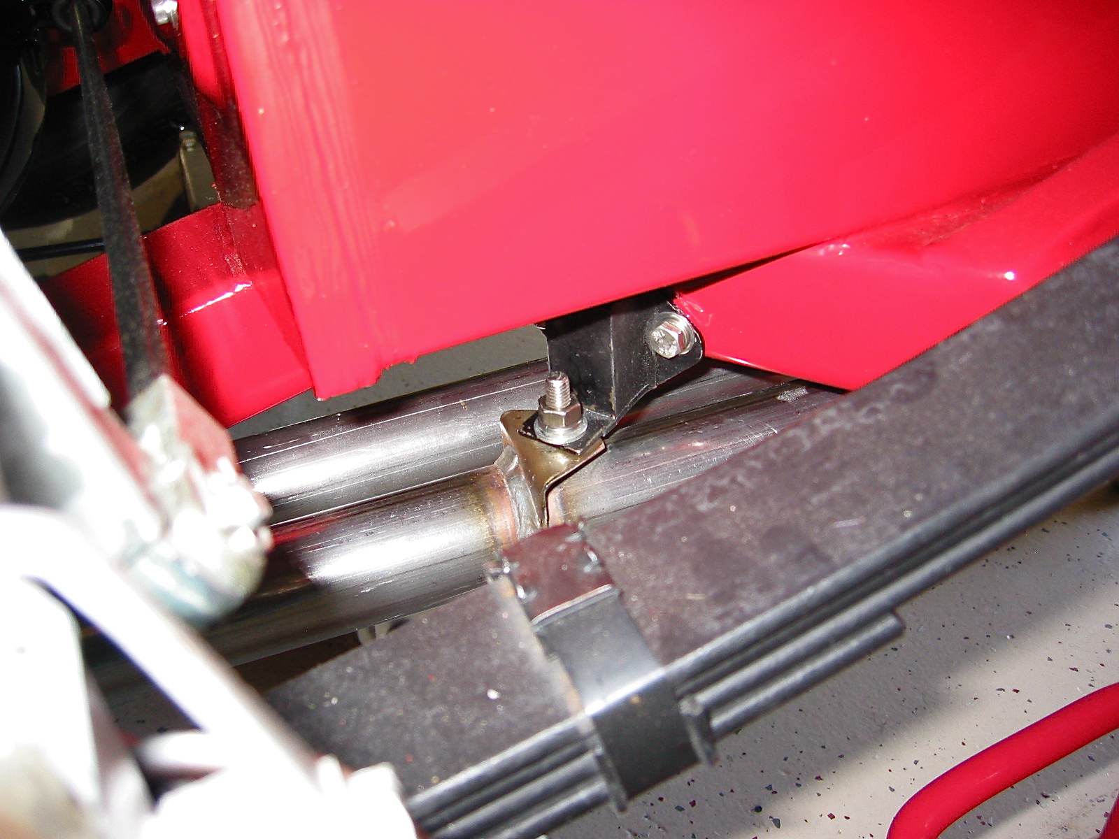
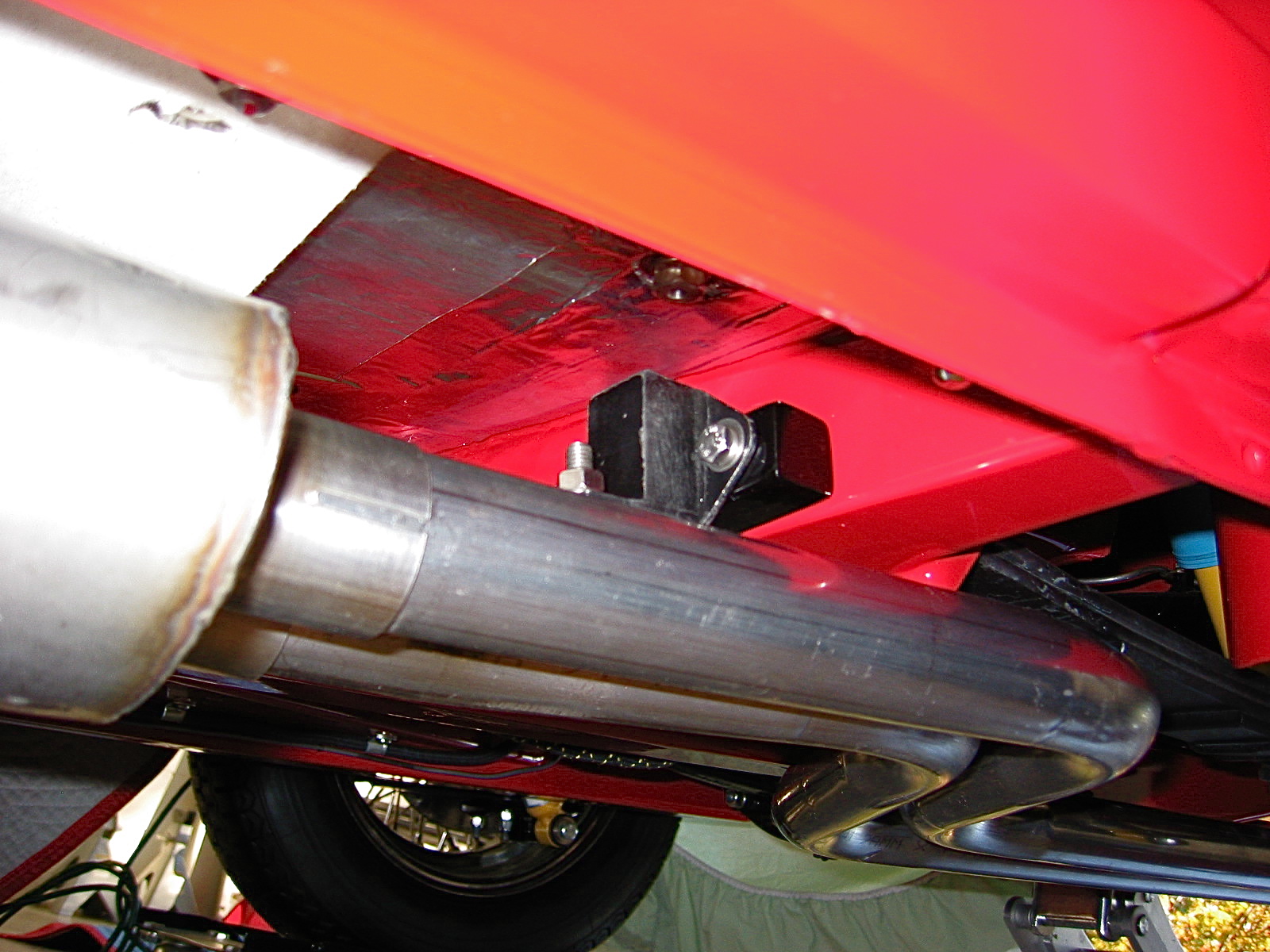
The exhaust headers were next to be installed. These are Phoenix headers and the full big bore exhaust system was sourced from AH Spares. The headers fit perfectly without any adjustments. I had them Jet-Hot coated in the sterling finish to keep them looking nice and to improve thermal qualities. Stainless steel flexible pipe (1 7/8”) was used to connect the headers to the stainless steel silencer and the big bore tail pipes. The front hanger bracket is in the wrong place for a BT7, so I made a custom spacer for that hanger. The rear hanger worked just fine. I was pleased with the final installation of the system.

Headers 1
Headers 3
Rear Hanger 2
Middle Hanger
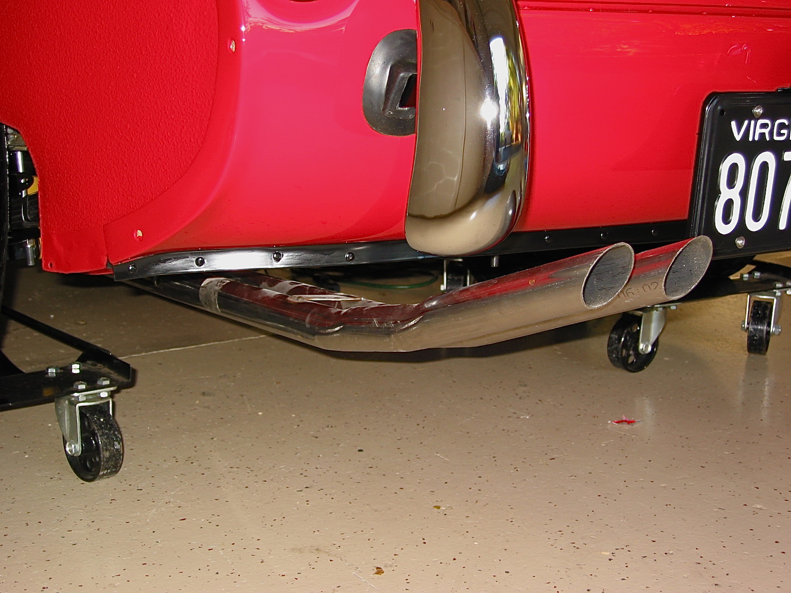
Tail Pipes 2
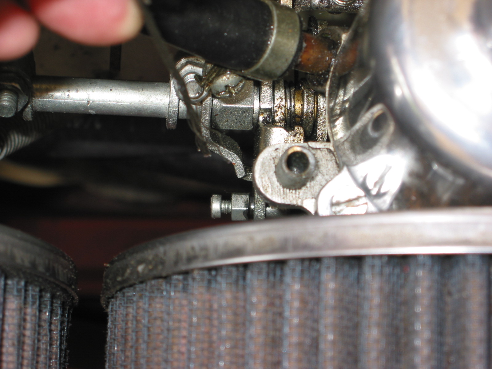
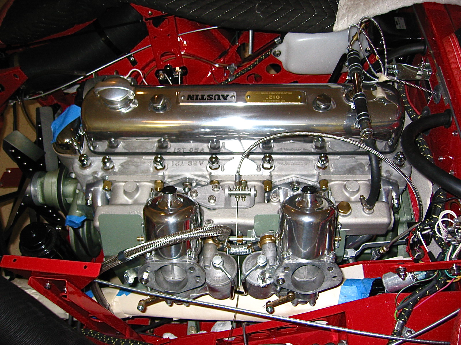
I assembled the intake manifold, heat shield and carbs to the Bloody Beast. Those lower mounting nuts are not easy to access! The stainless steel flexible fuel lines were connected to the steel fuel line and to the two SUs. I had to pull everything off the engine when I realized that I had not yet attached the manifold fuel drain pipes!! As it turned out they are very close to the header pipes, but after checking with a few people who are more informed about such matters than me, I think I am comfortable leaving them as they are. They should have been installed along with the vacuum line BEFORE the rest of the engine components!!!!
Front fuel drain line

Engine from above

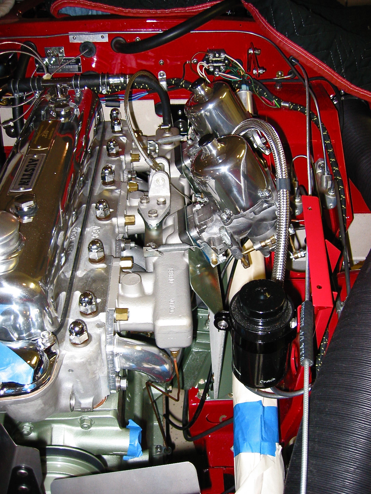
Engine from right
Engine LH view
Engine front view