Chapter 83 Week Fifty-Three December 17, 2007

This week begins my second year of restoration assembly. I have some time off in the next two weeks so I am hopeful that at the end of the Christmas holiday I will have my front body components on the car.

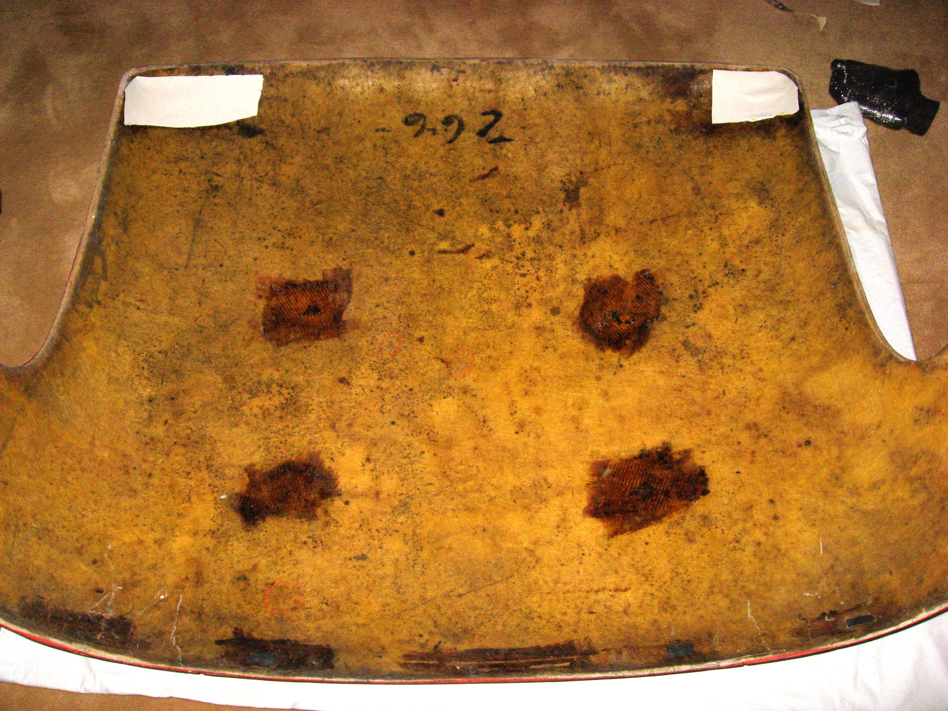
While waiting for the carb repair, I decided to start a little work on the hardtop assembly. Most of my hardtop restoration components came from Bill Bolton. The hardtop fabric he supplies is very close to the original. I has previously refurbished the headliner frame and had it along with the front cushion covered by Gerry Smith at Classic Upholstery. I glued the fabric to the lower hardtop aluminum cant rail.

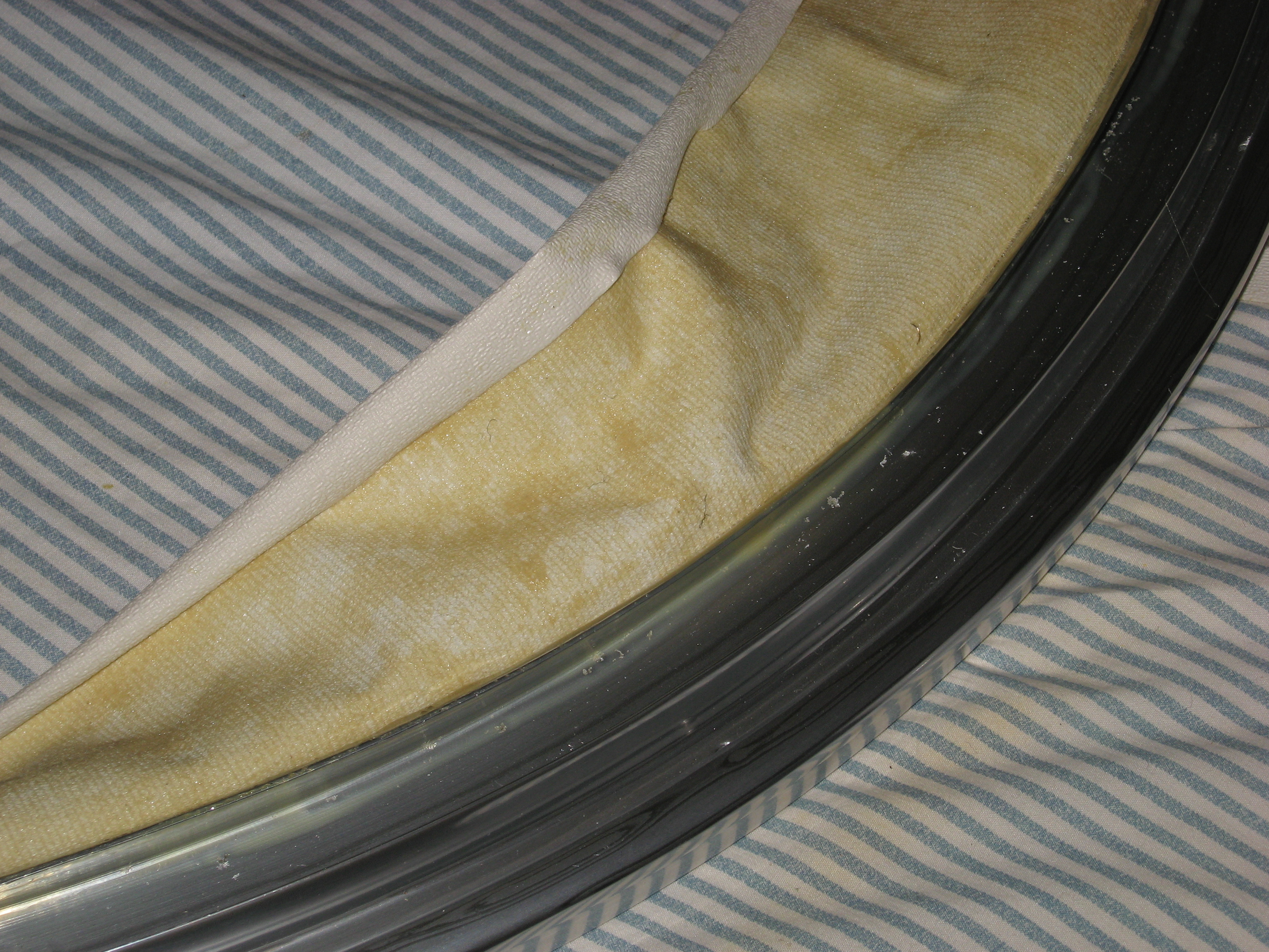
hardtop fabric on rail 2

hardtop fabric on rail 3

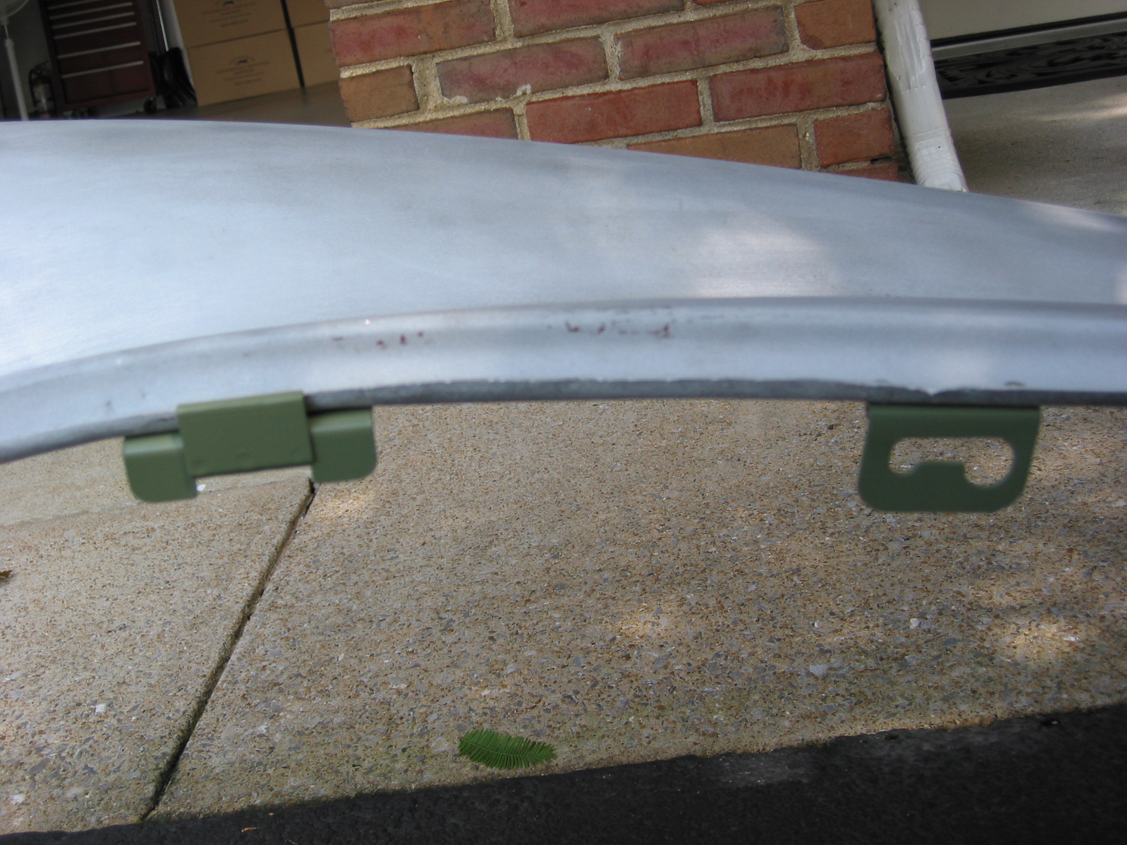
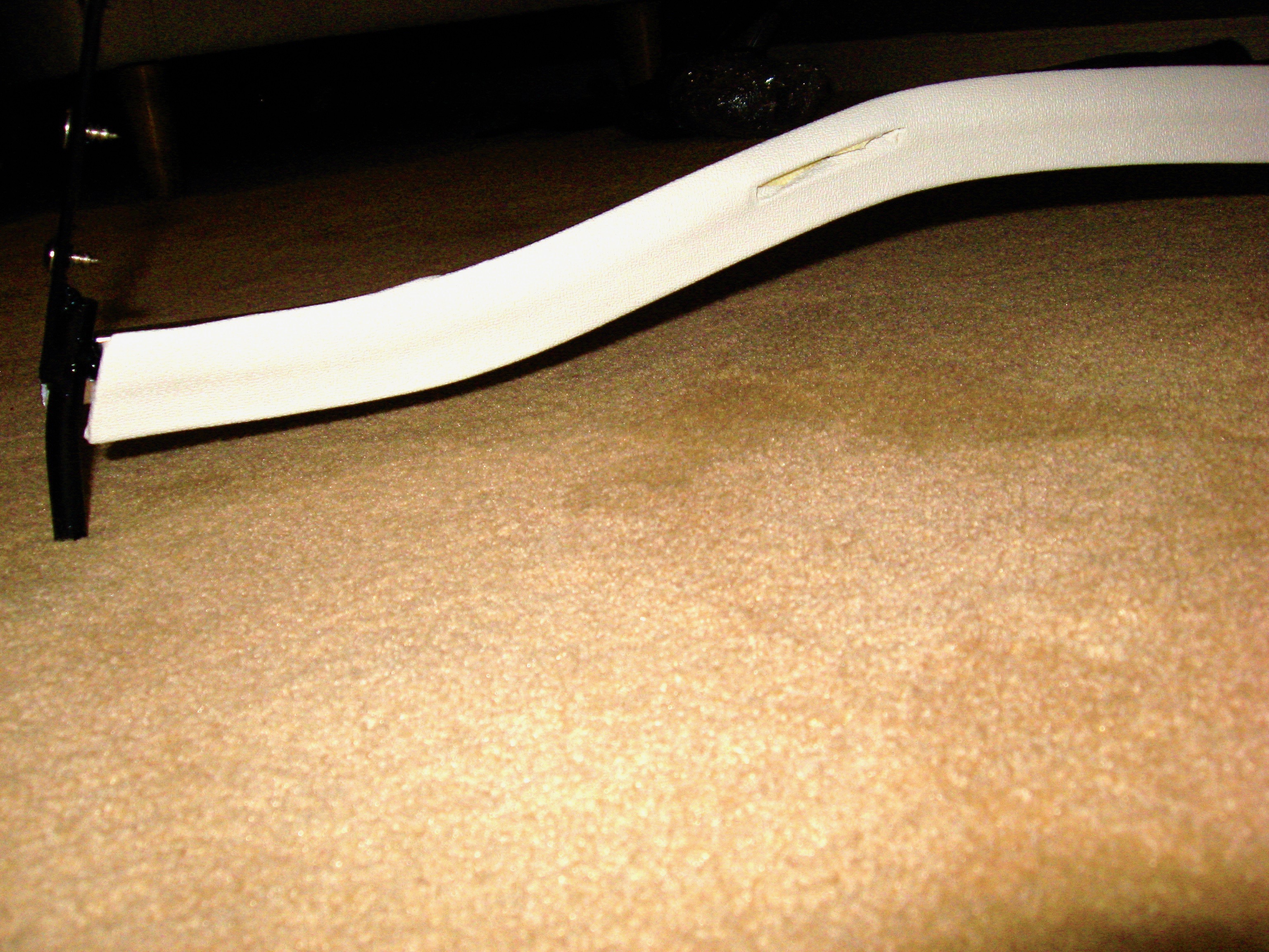
Fabric was also glued into the corners of the hardtop where the front mounting “J” hooks are located.

hardtop corner fabric

Then I glued some carpet padding onto the hardtop to provide cushion for the headliner frame rails.

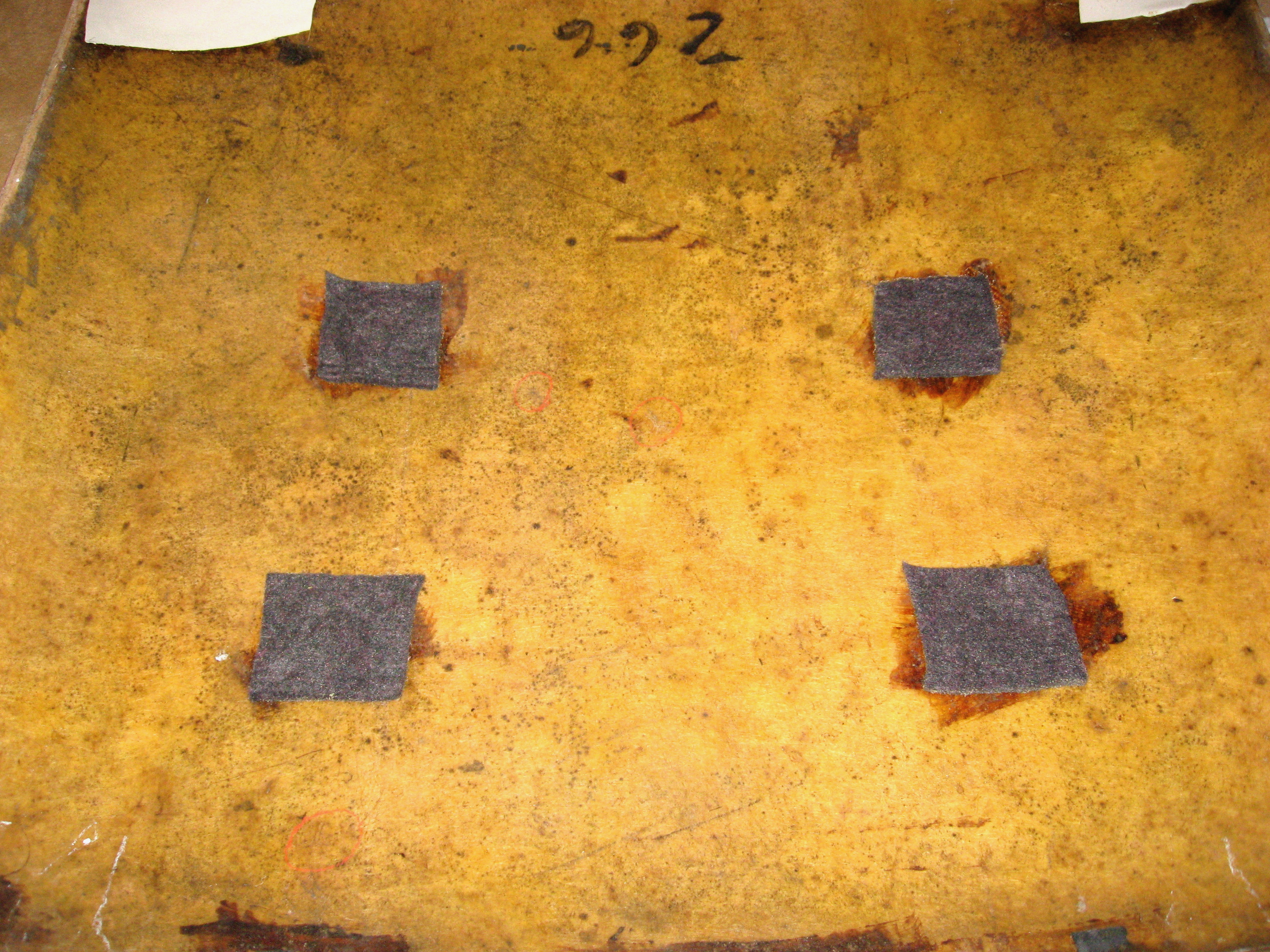
hardtop carpet cushion for headliner rails

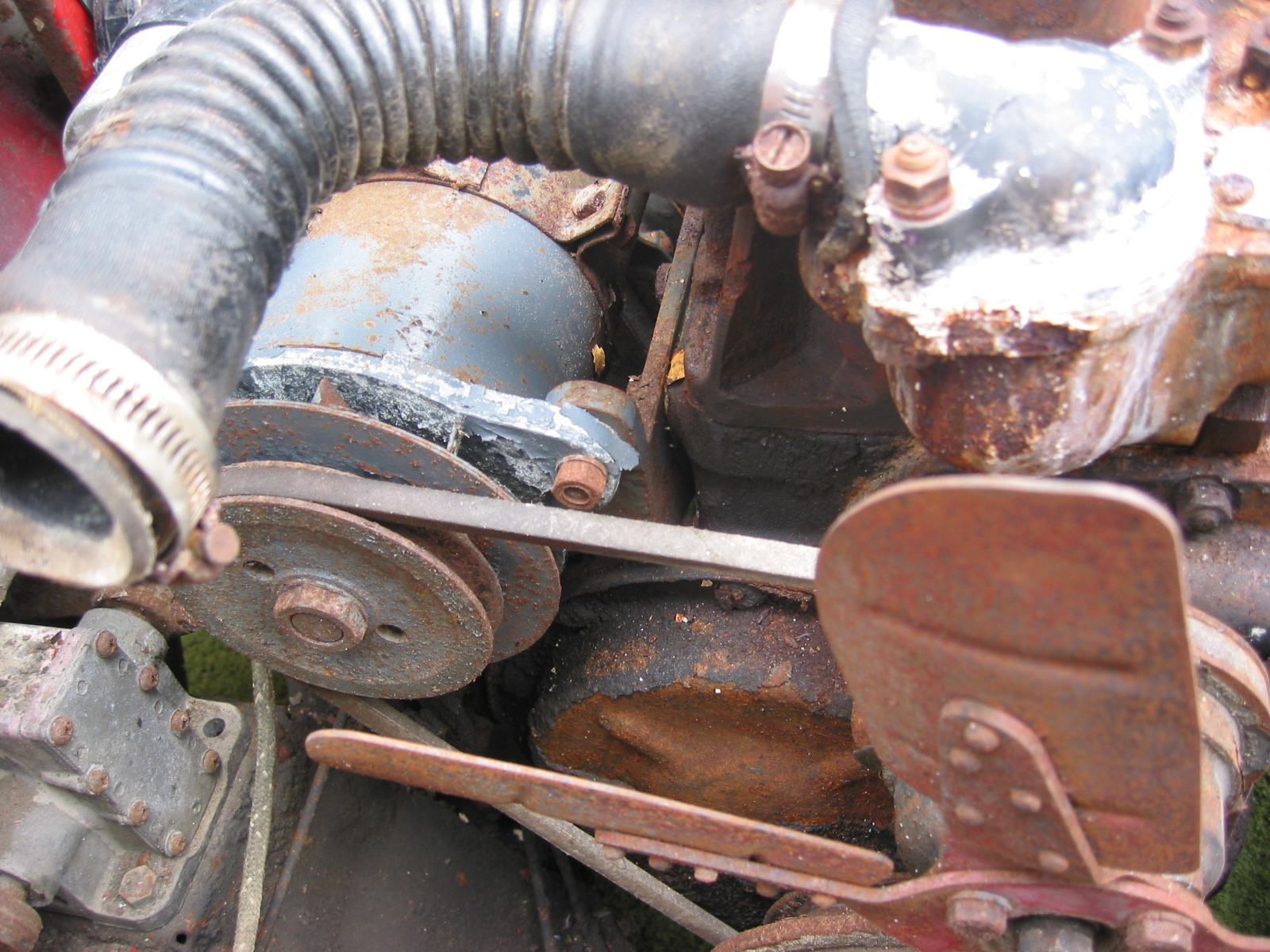
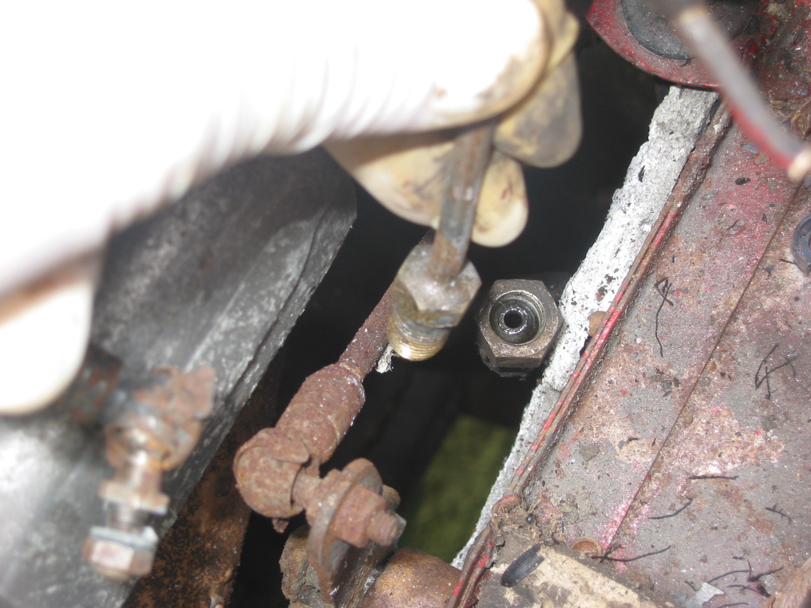
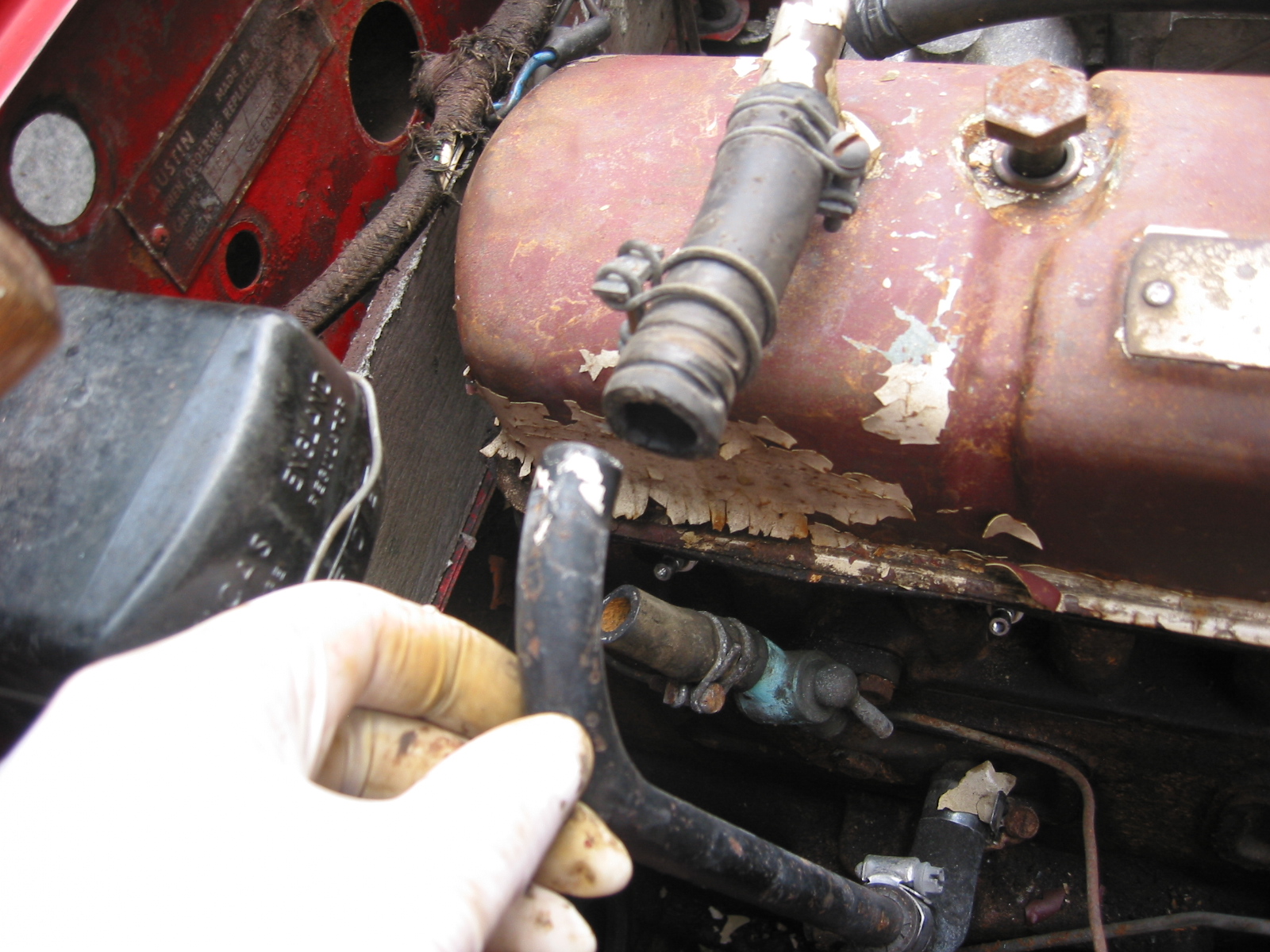
My repaired front carb returned from Joe Curto yesterday (December 18). Joe replaced the diaphragm. I installed the carbs last night and pleasantly, no leaks! Now I will leave the hardtop work and return to installing the body.

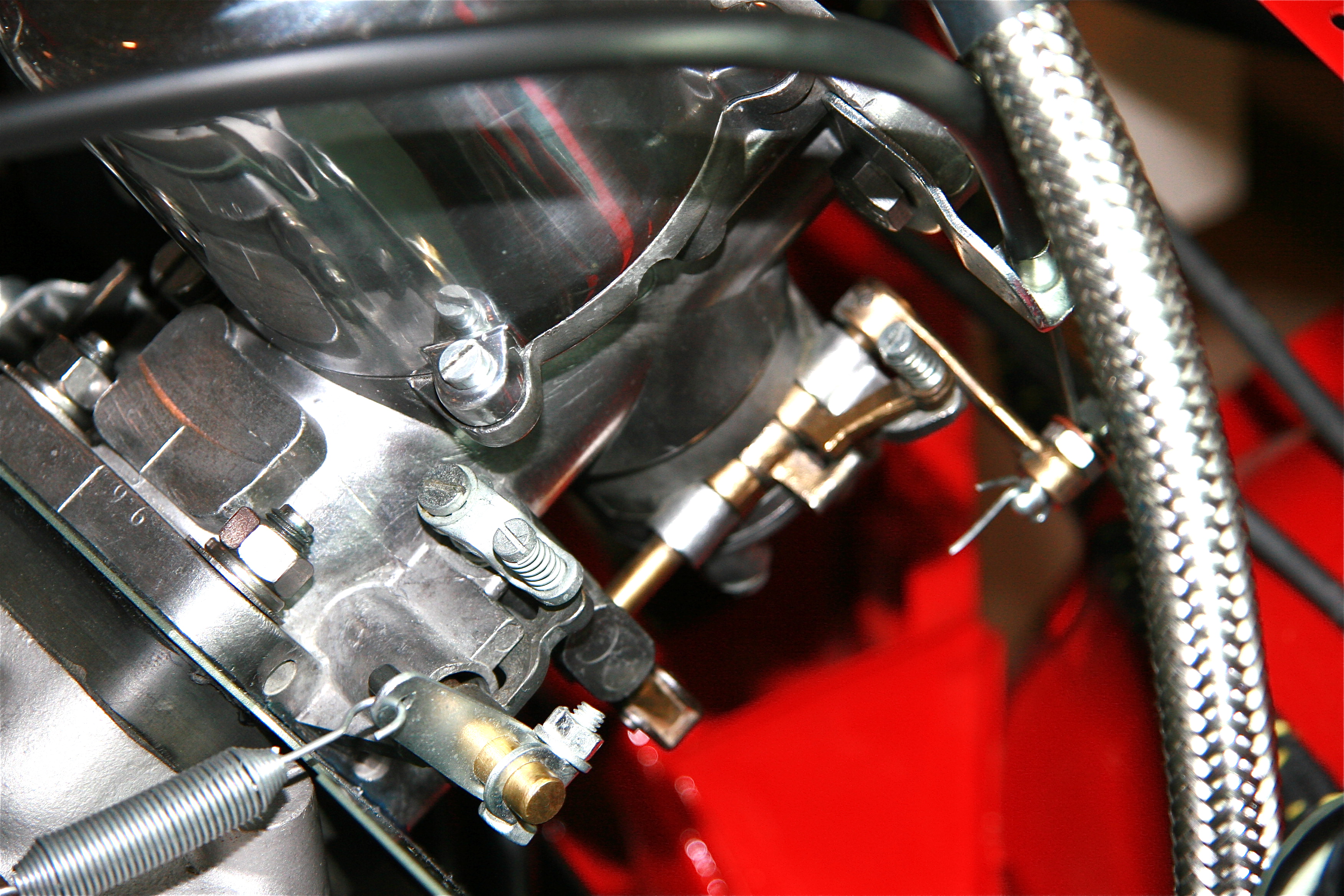
Front SU carb re-installed

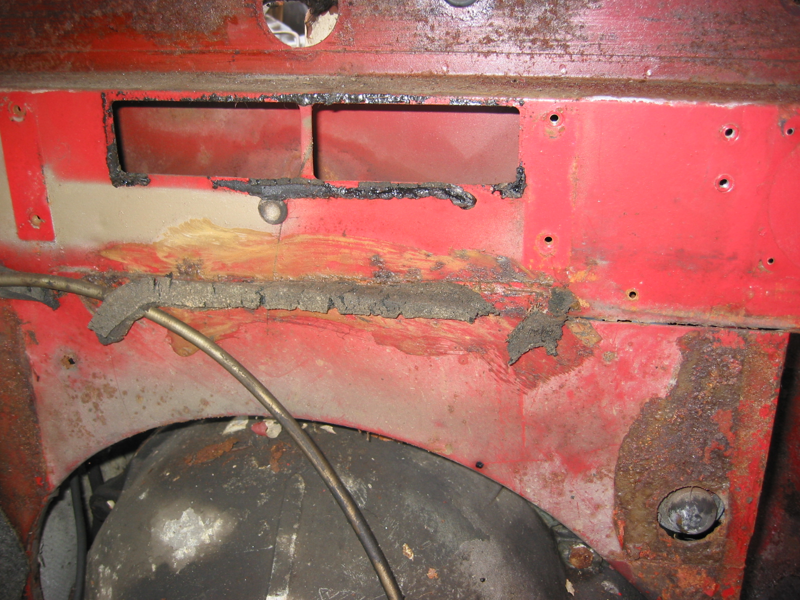
I covered all of the edges of the scuttle that come in contact with the front shroud(bonnet surround) with 3M strip caulk. This will prevent heat, fumes and water from entering the cockpit. To make sure I had adequate build up of the caulk, I used a tip from Jack Brashear. I covered the strip caulk on the scuttle with wax paper, installed the shroud and then pulled it off. Where the strip caulk was not pressed against the the wax paper I added more caulk and repeated the process until I was satisfied that I had enough caulk in place.

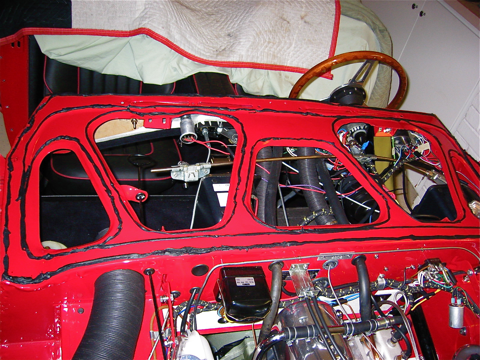
Shroud strip caulk 2

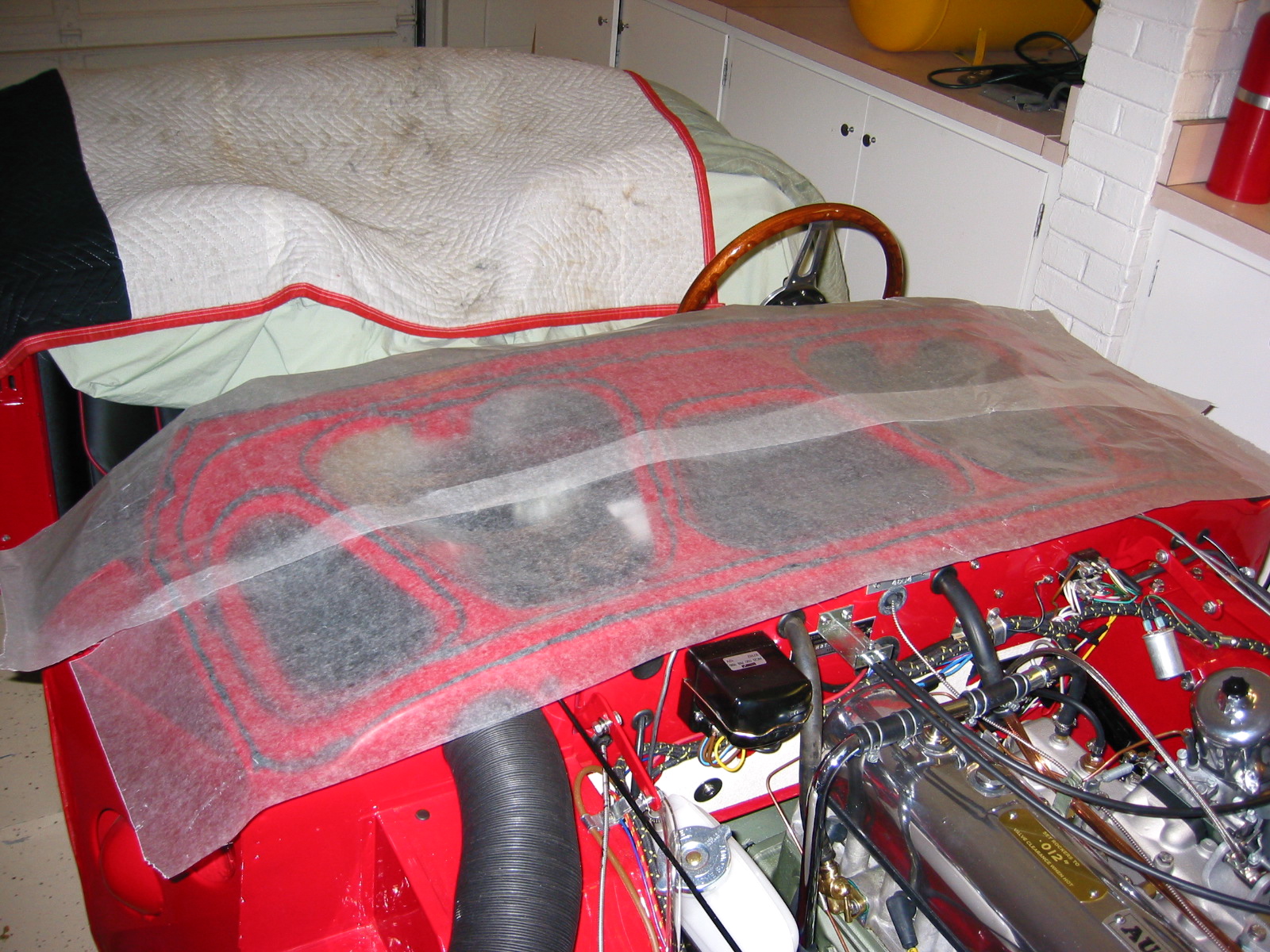
Shroud strip caulk 1

Ready for the shroud 2

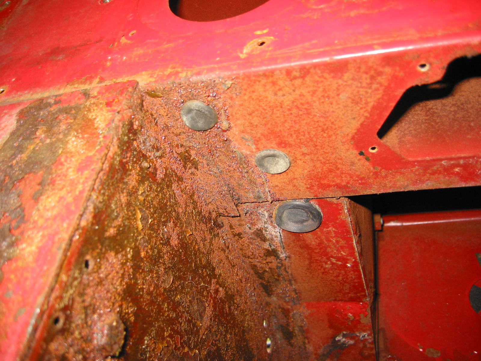
Securing the front shroud to the superstructure was the next step. I began by installing 3/16” aluminum pop rivets in the rear of the shroud along the dashboard flange (5) and scuttle edges(2 per side).
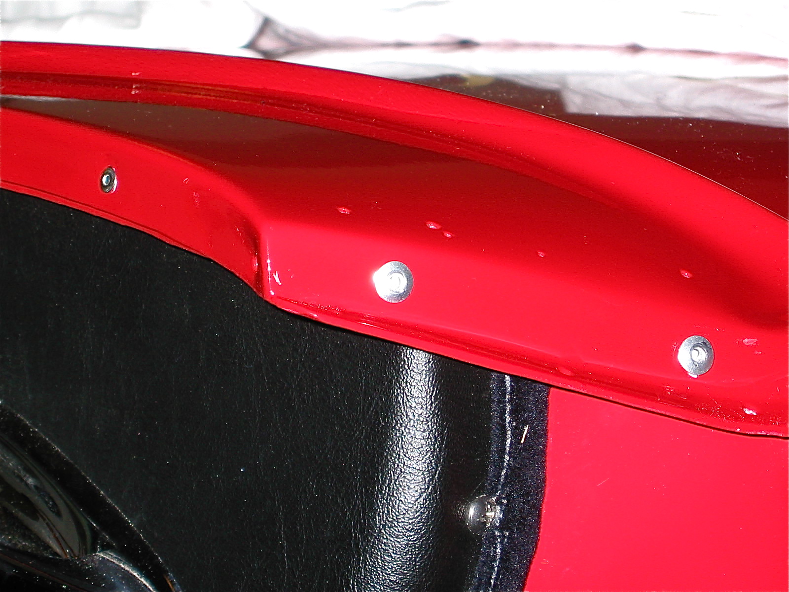
Shroud rivets

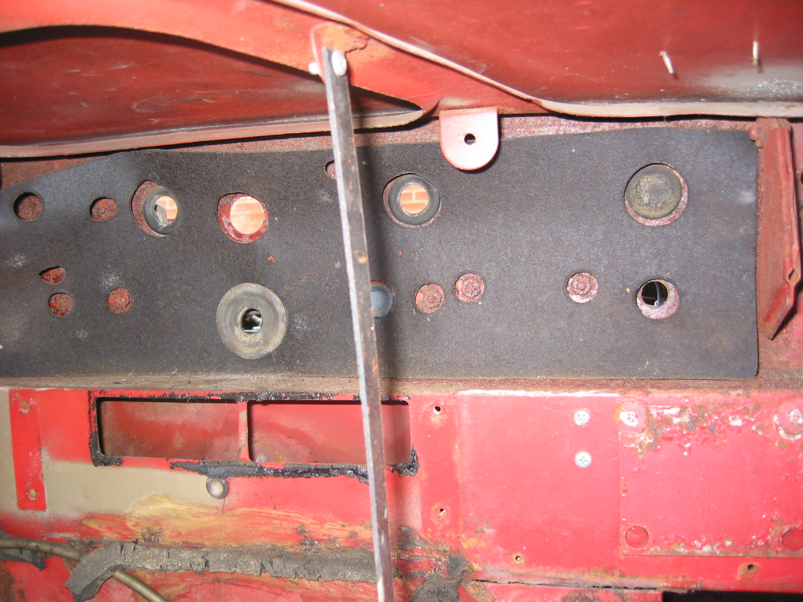
I then installed five countersunk flat head screws through the rear flange of the bonnet opening into the edge of the firewall.

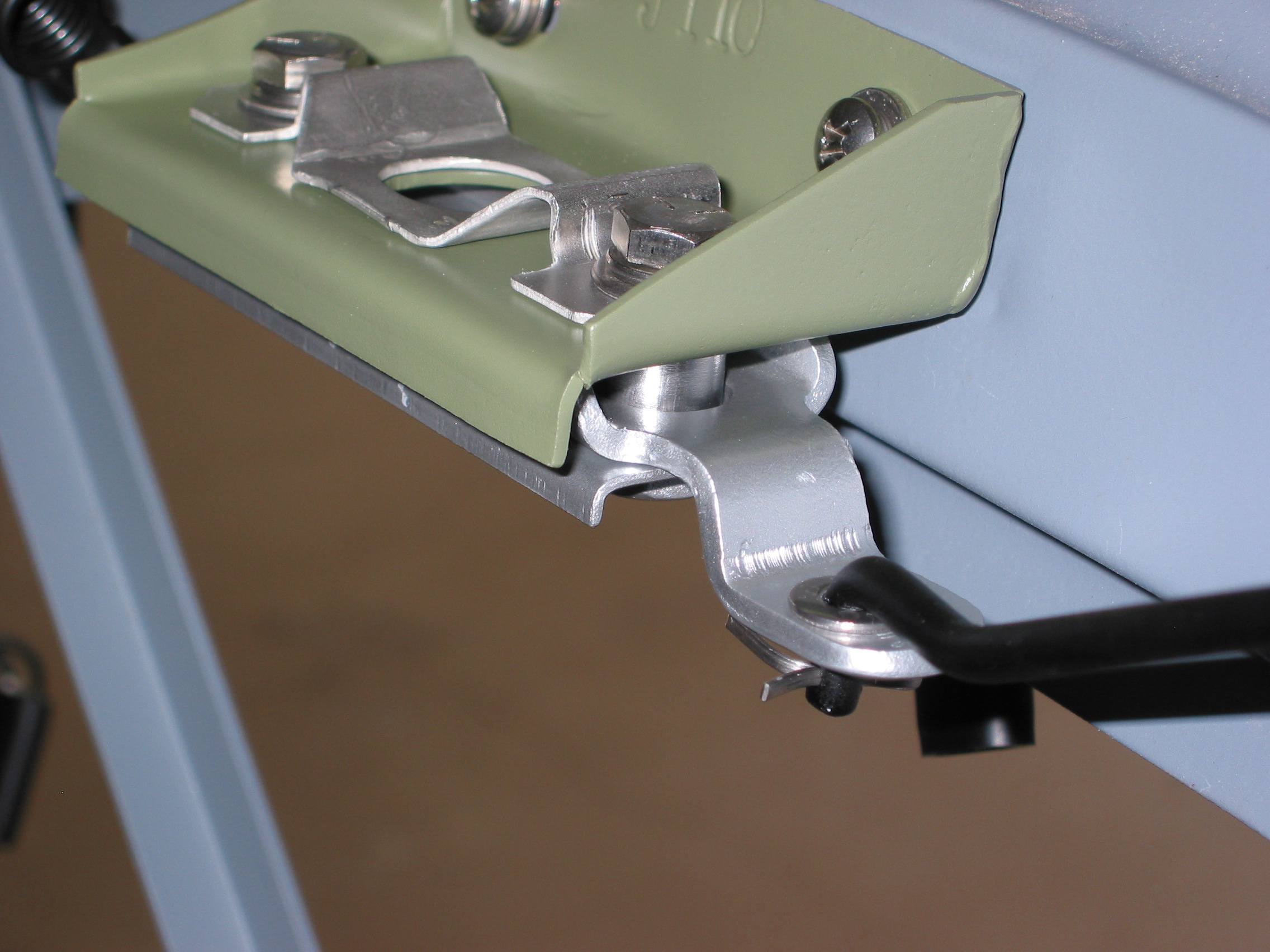
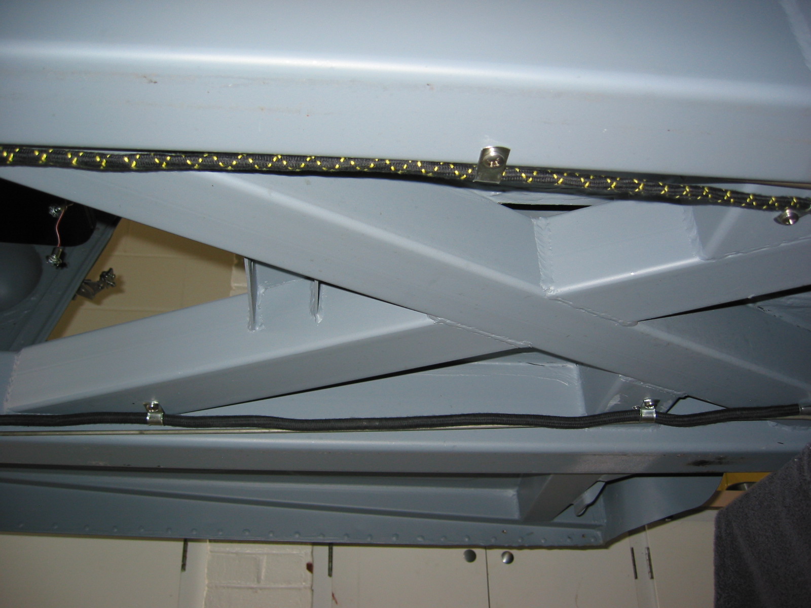
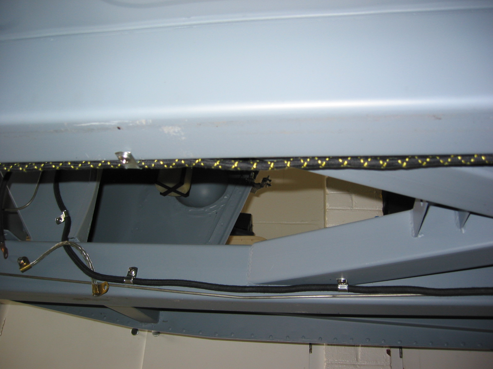
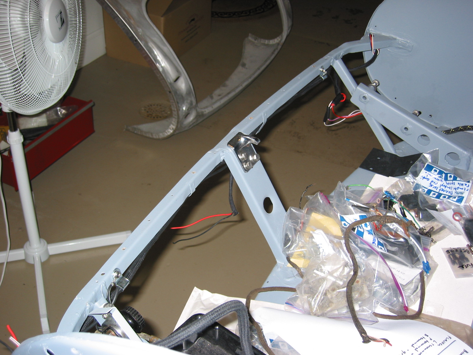
Four bolts, washers, and nuts fasten the frame rails to the shroud at the front of the car. The frame rails should fit “inside” the shroud. Three #10 flat head, countersunk machine screws with washers and nuts fasten the front flange of the bonnet opening to the superstructure.

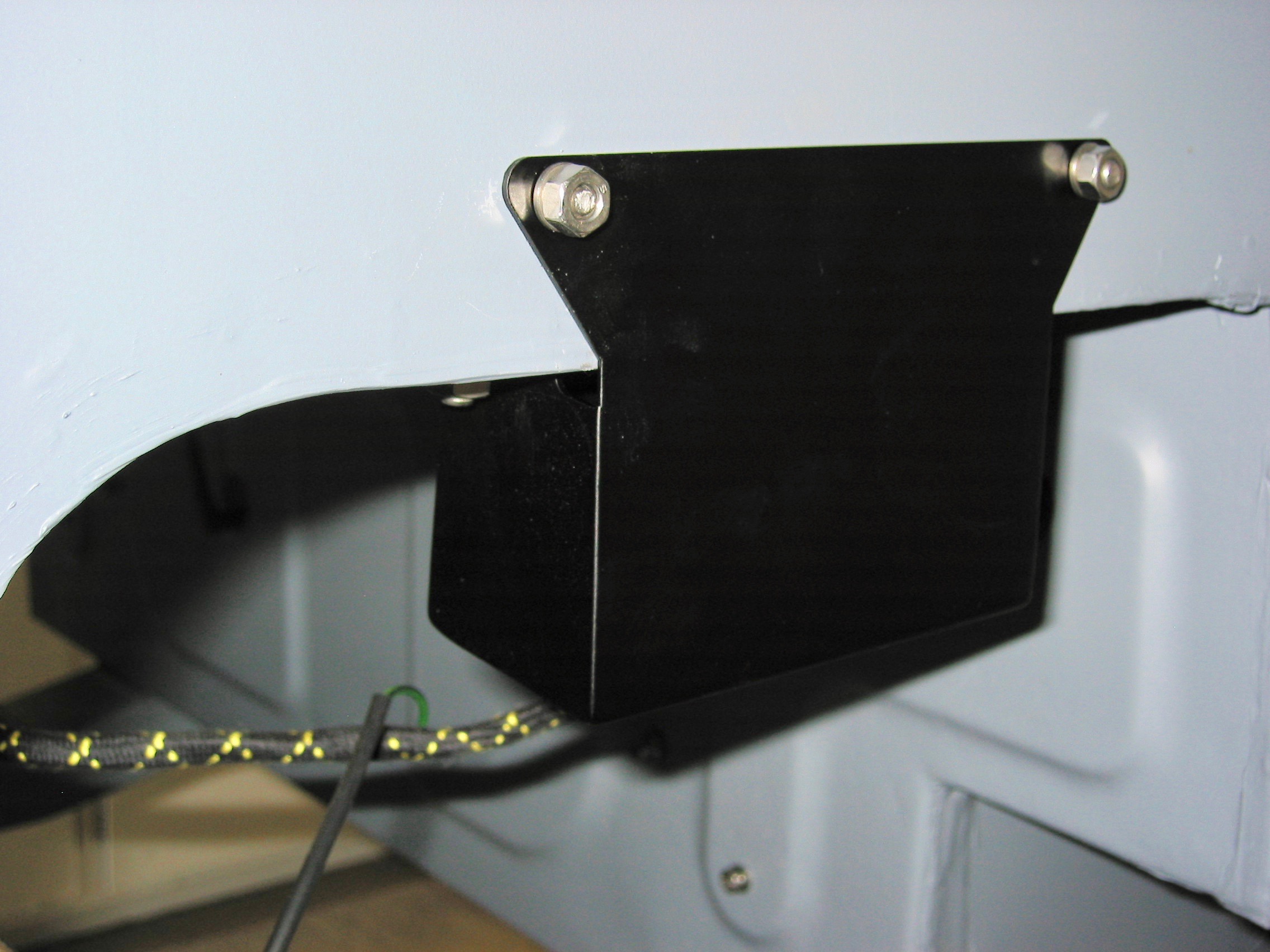
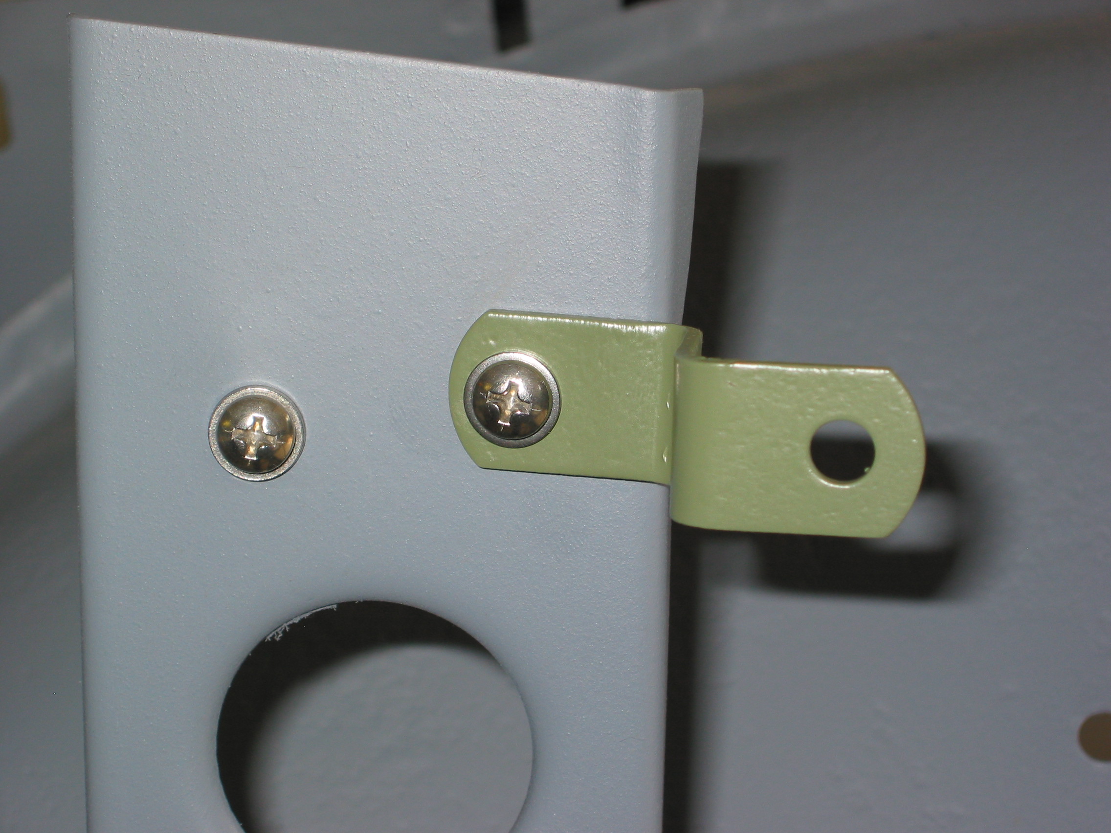
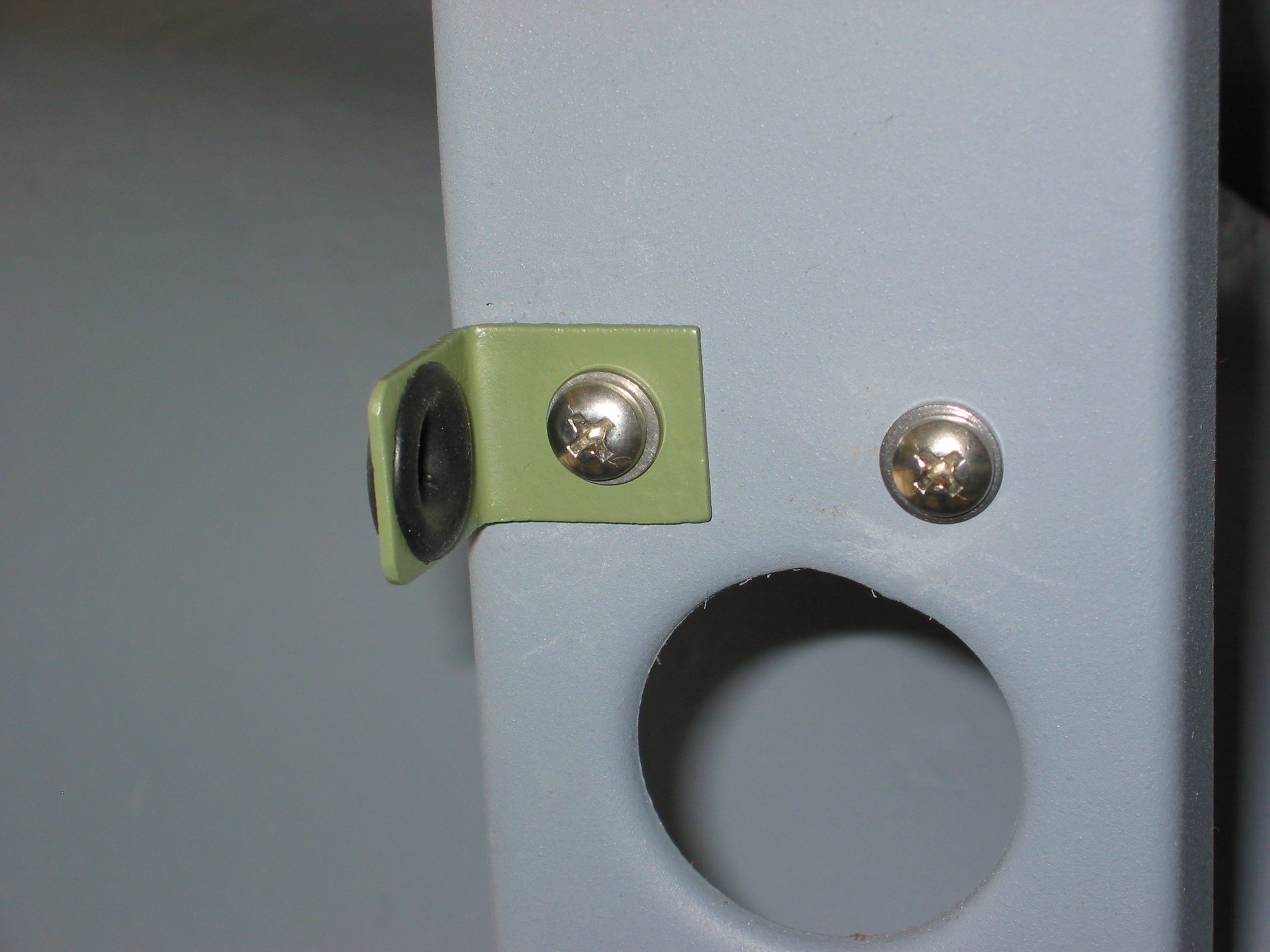
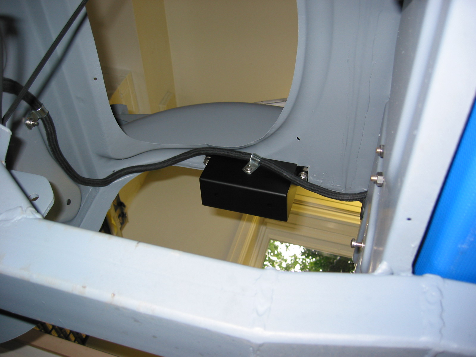
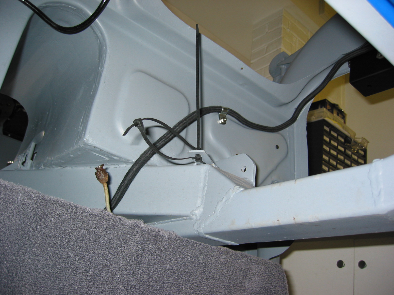
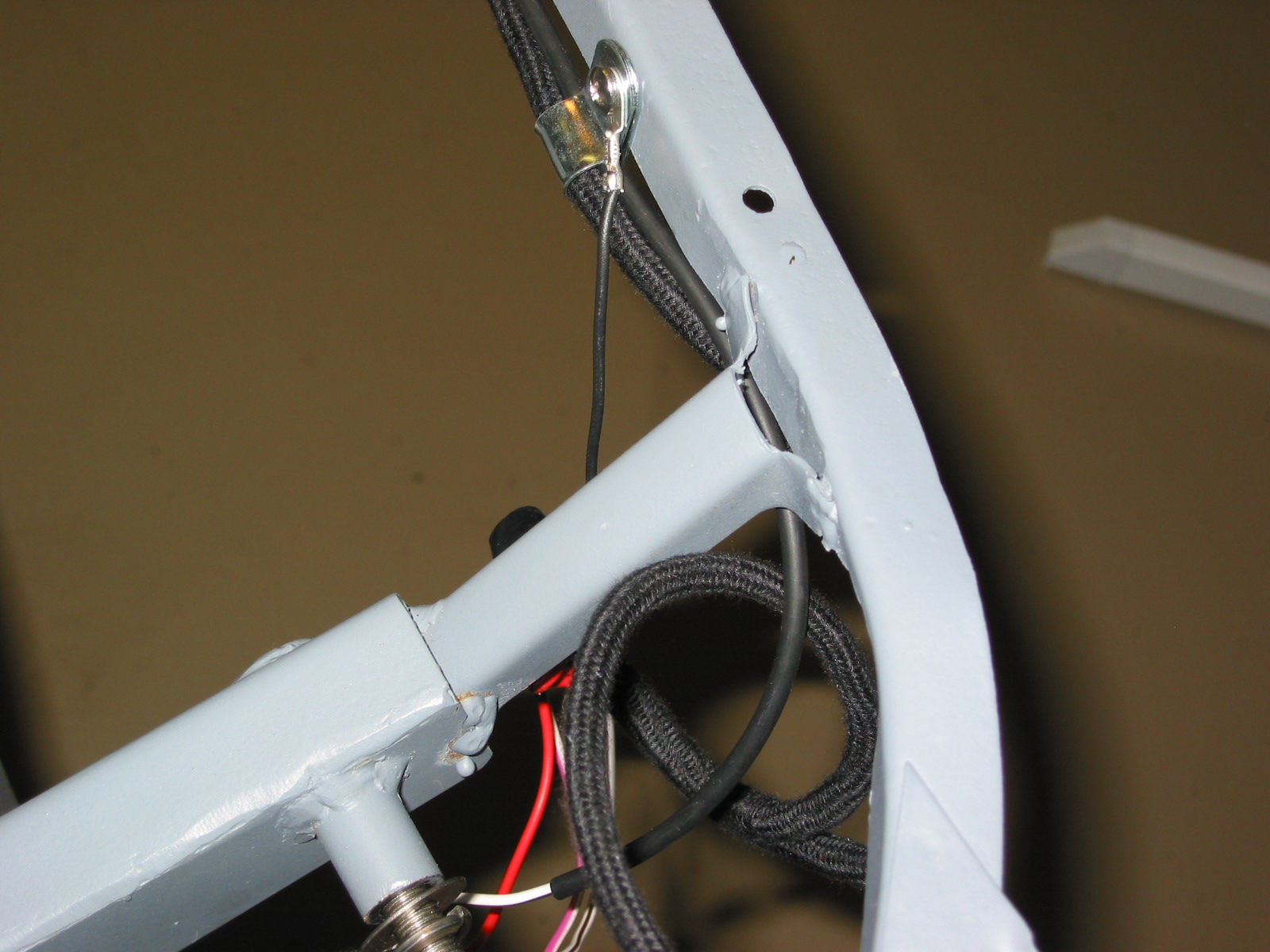
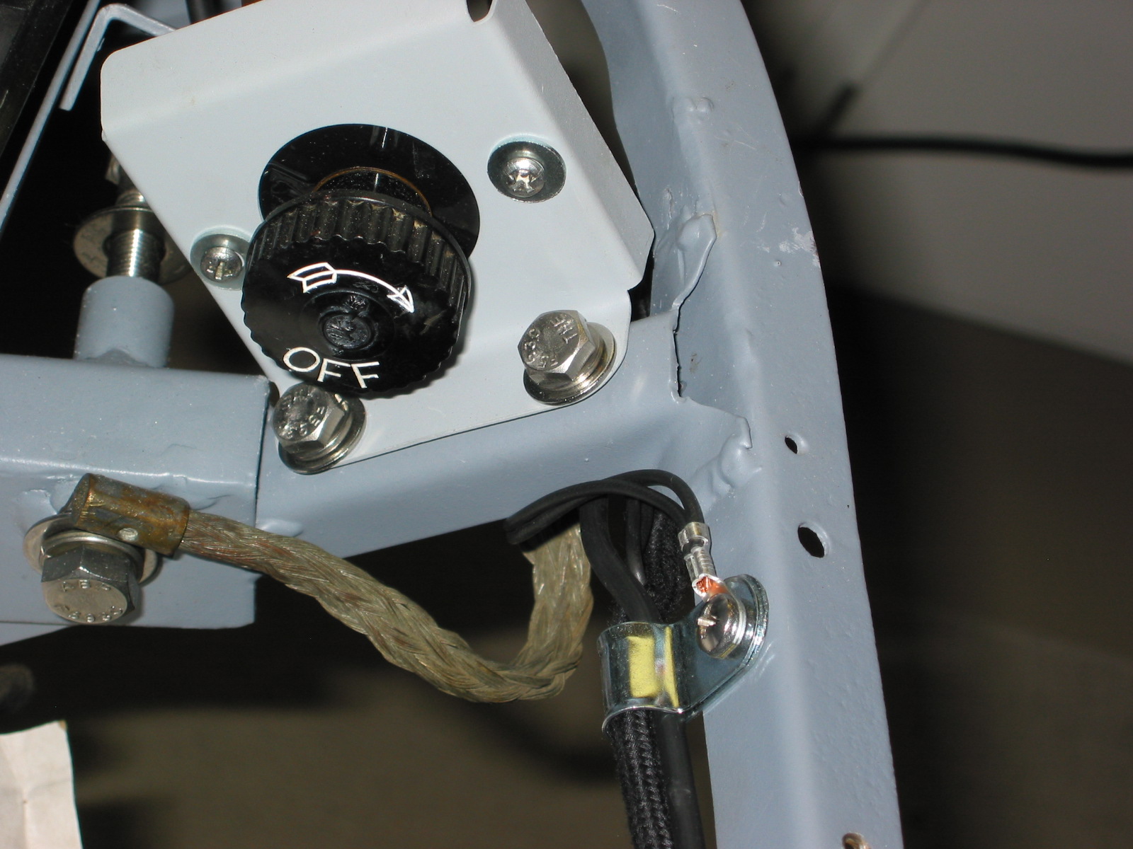
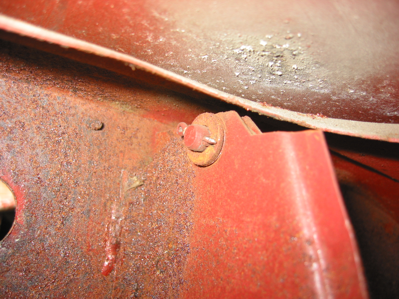
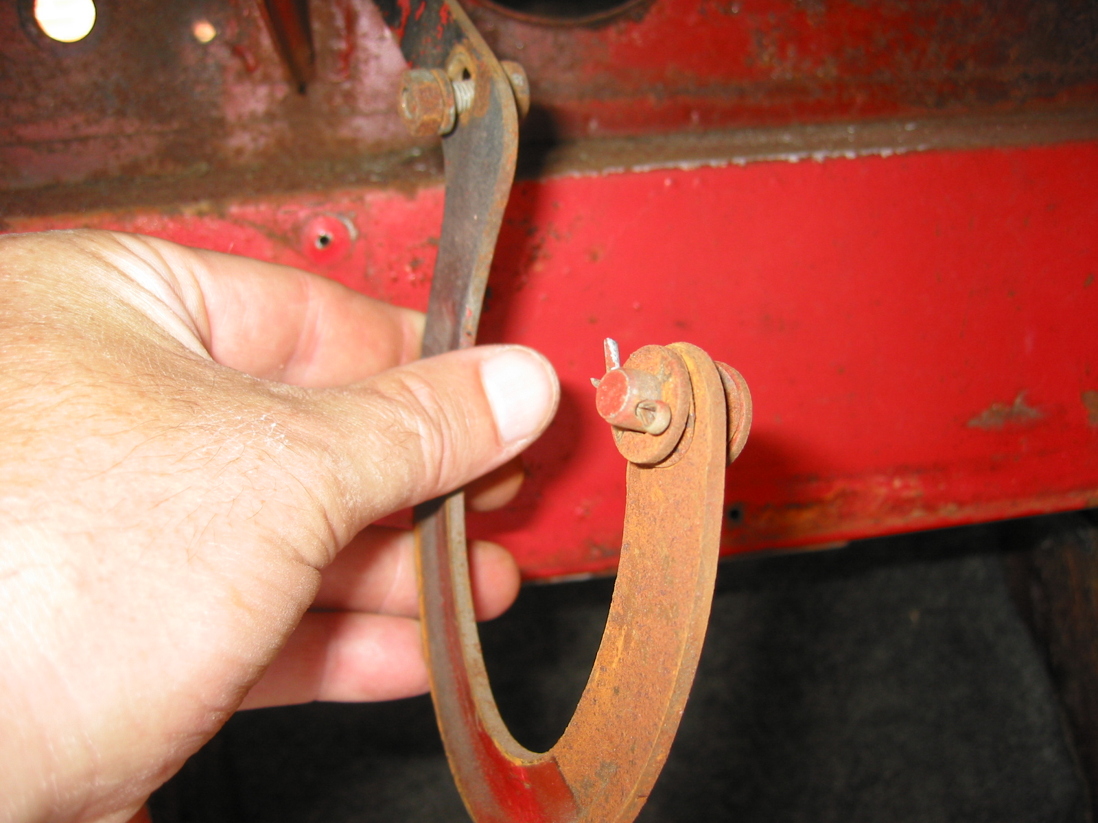
Two #10 flat head, countersunk machine screws with washers and nuts fasten each of the vertical shroud support brackets to the shroud. On the RH passenger side of the car, one of these screws, along with another, is also used to fasten the bonnet prop rod stay bracket.

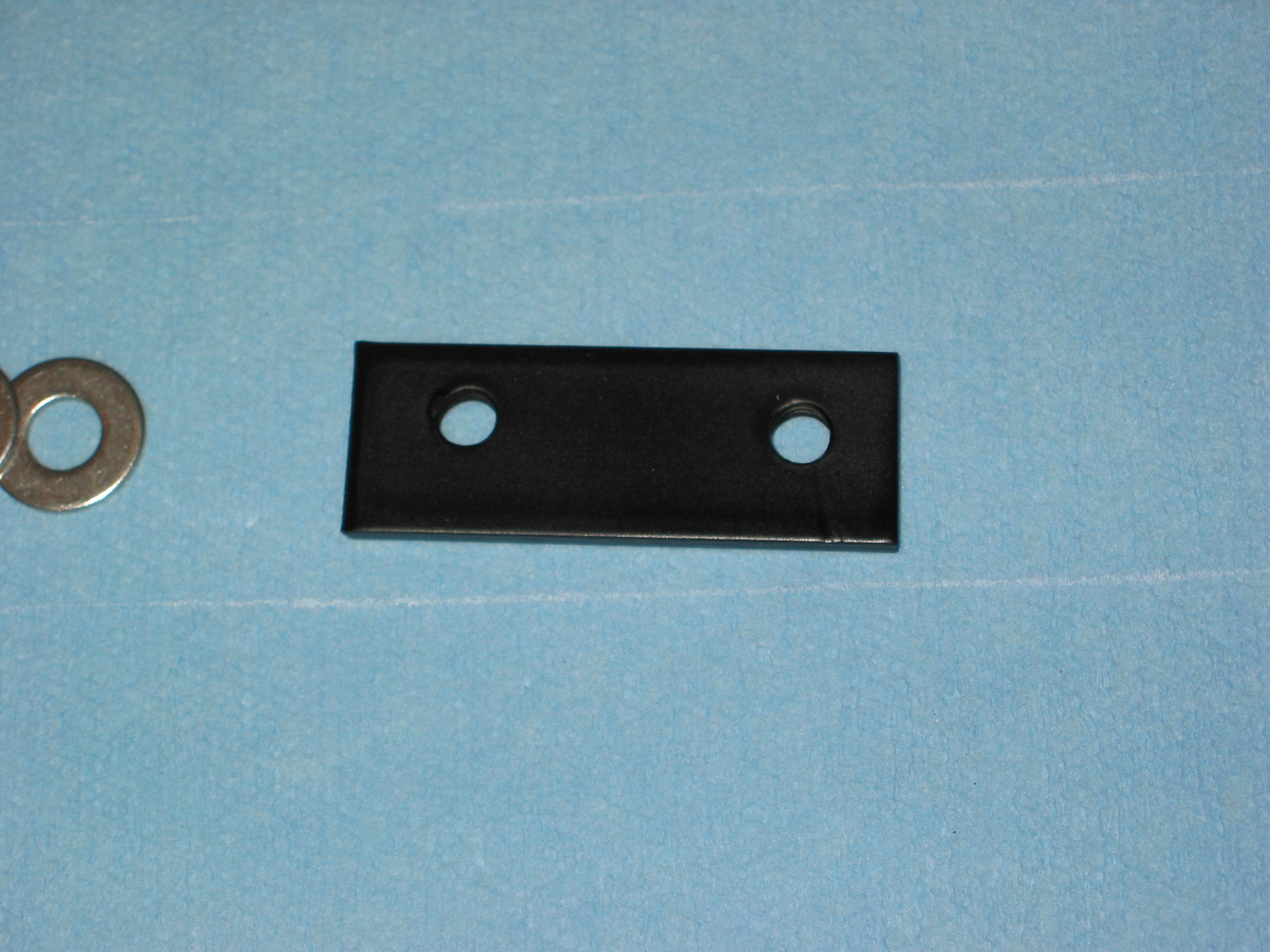
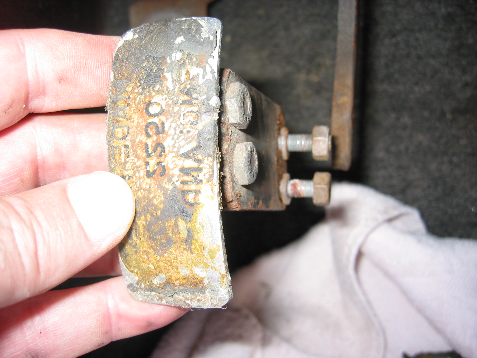
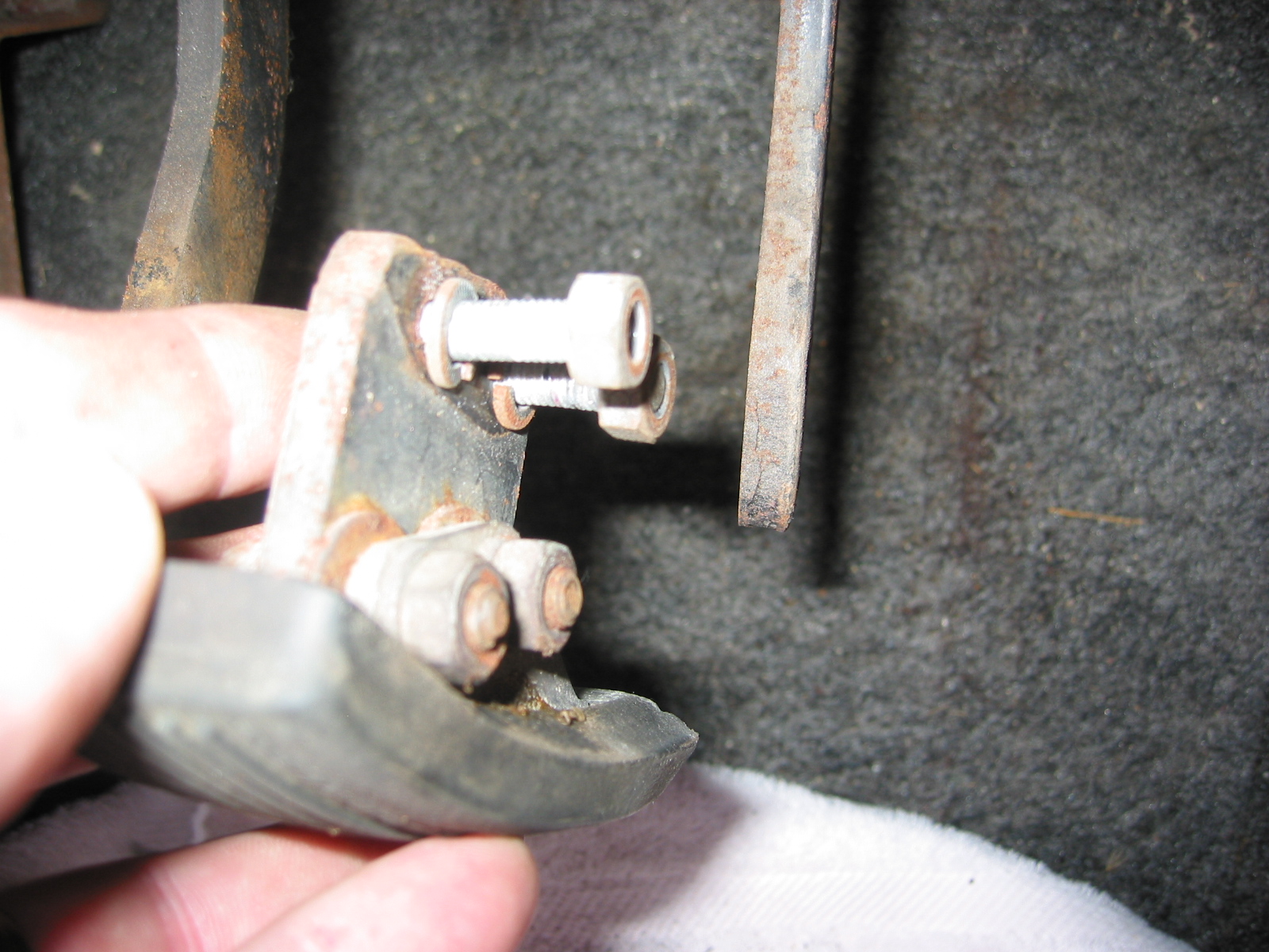
Hood prop rod stay bracket

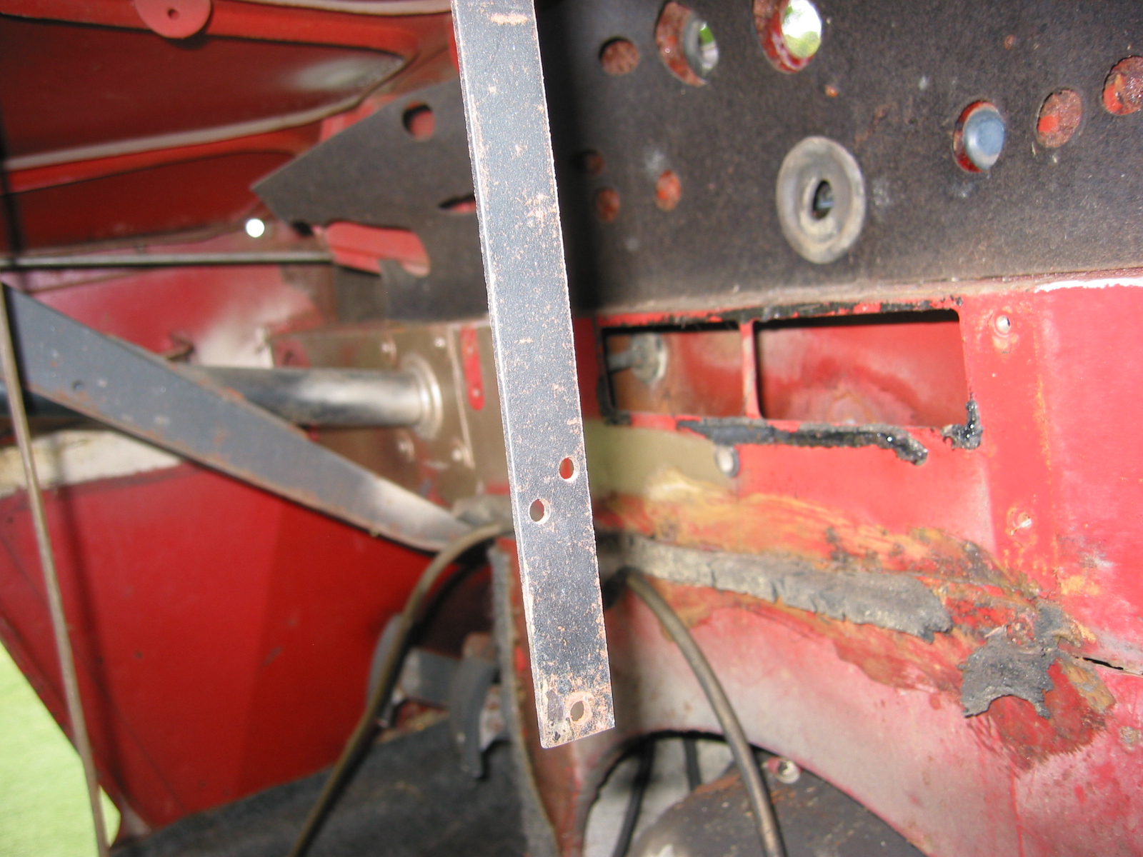
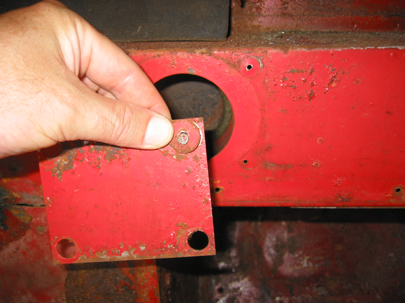
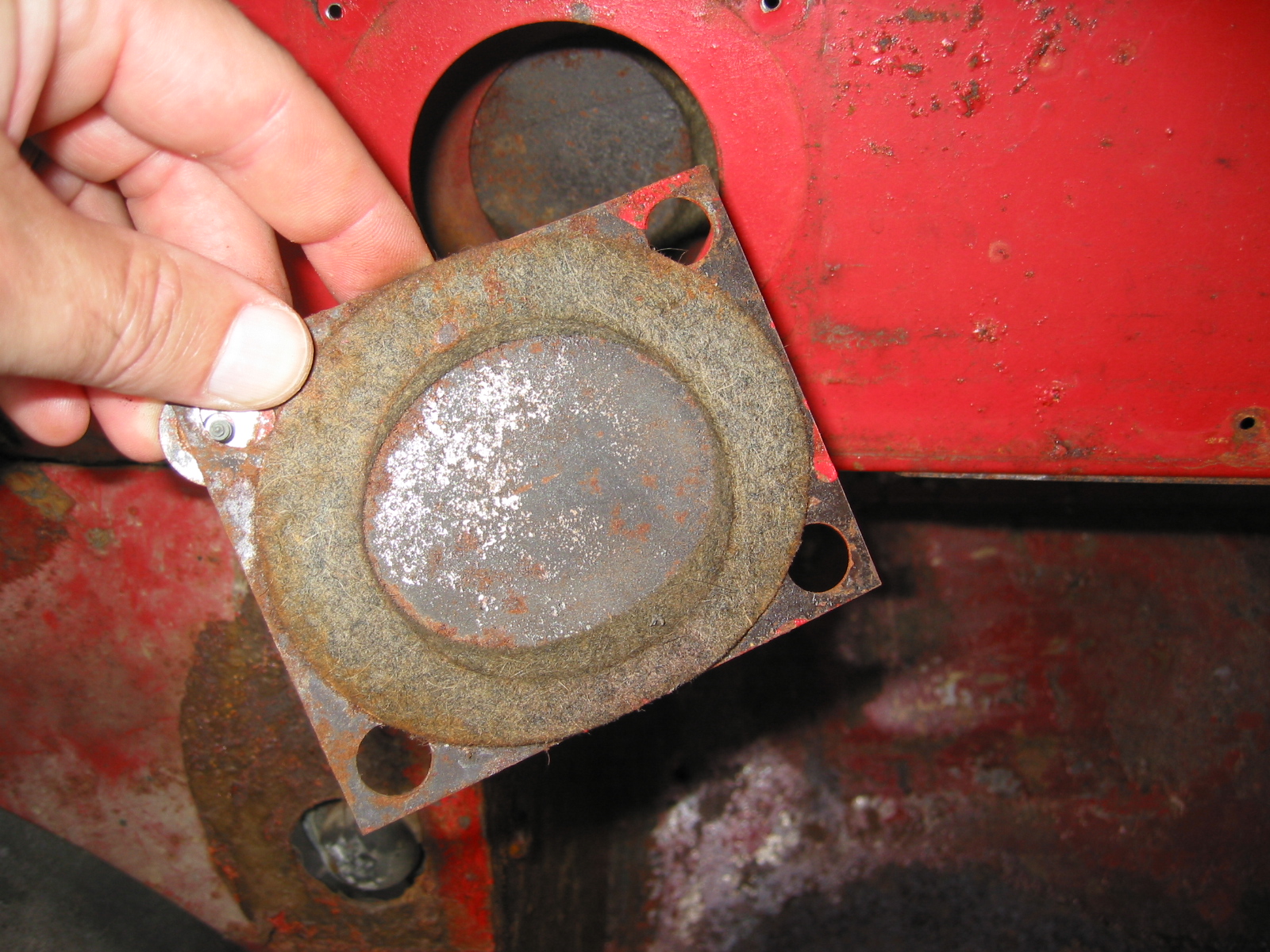
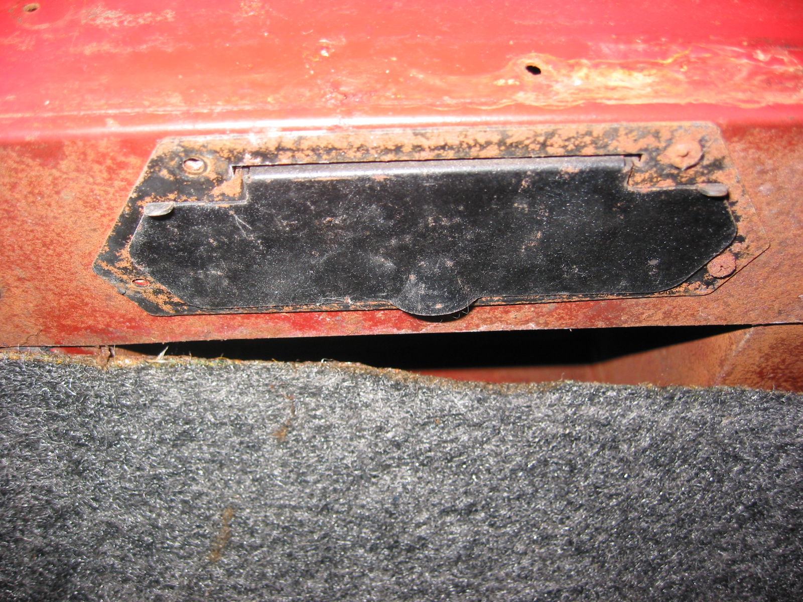
The front shroud was now fastened in place! I then attached the carb access panel and I was in business. The panel measurements are in the image below.

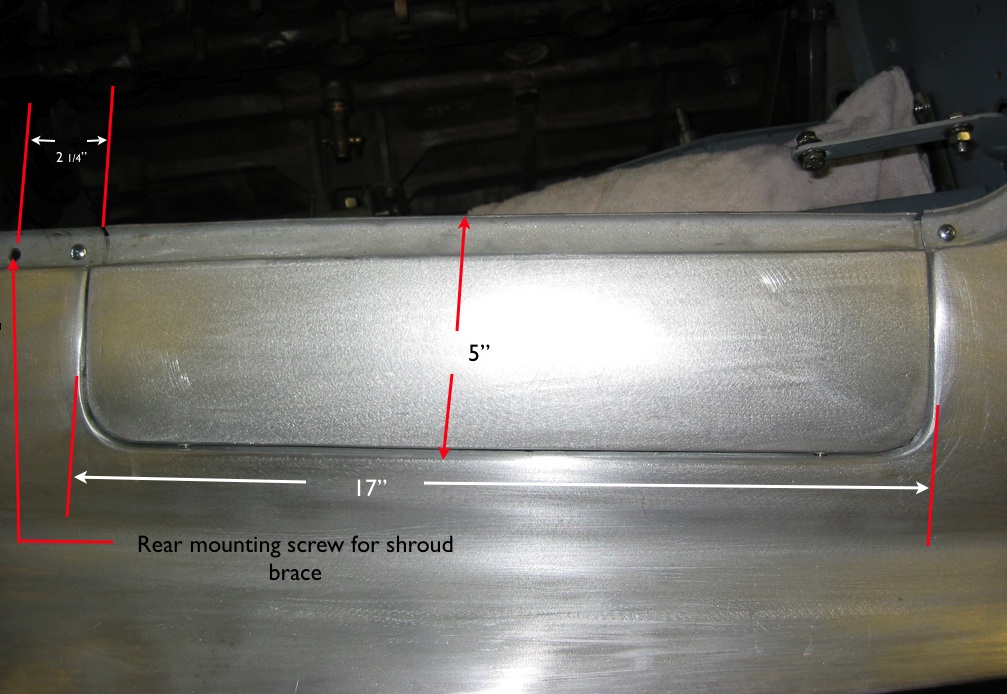
carb access measurements

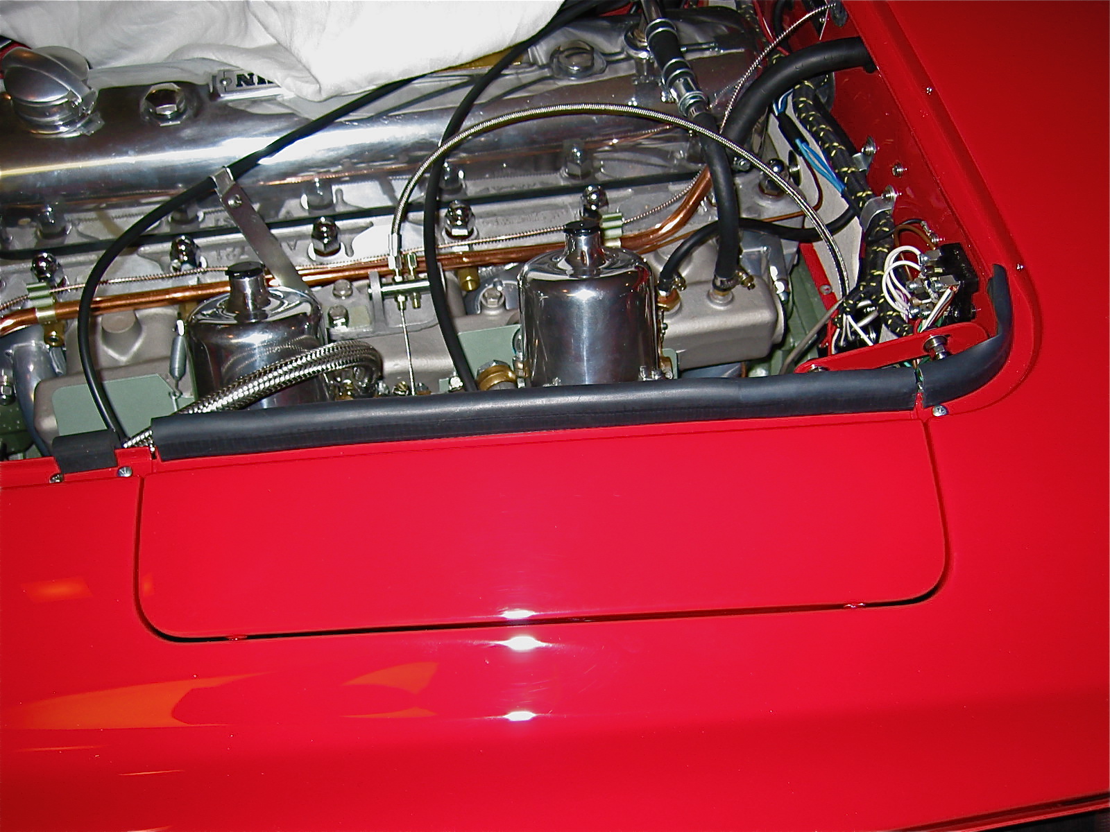
Carb panel installed

I had a surprise visit from my 9 year old grandson, Tyler. As the photo shows he is getting ready to drive the “Bloody Beast.”

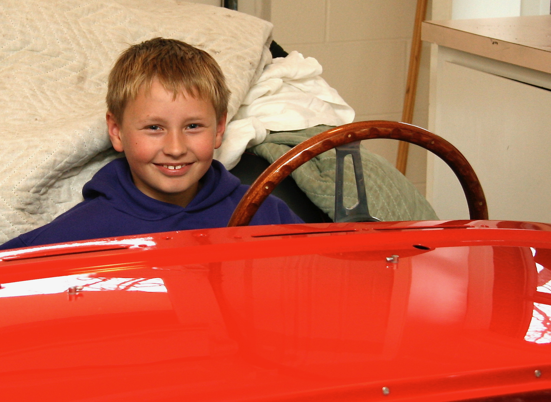
Tyler ready to drive

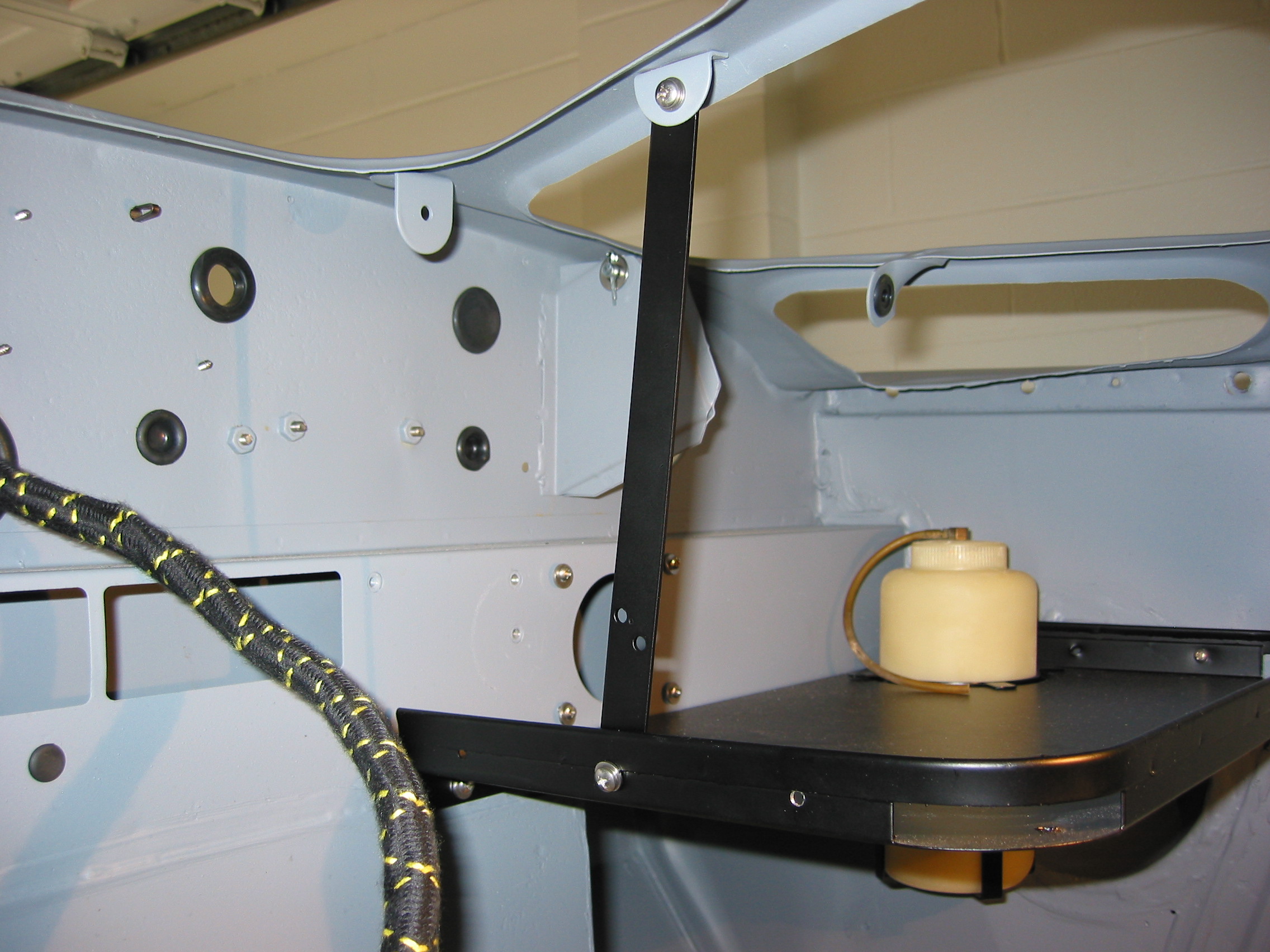
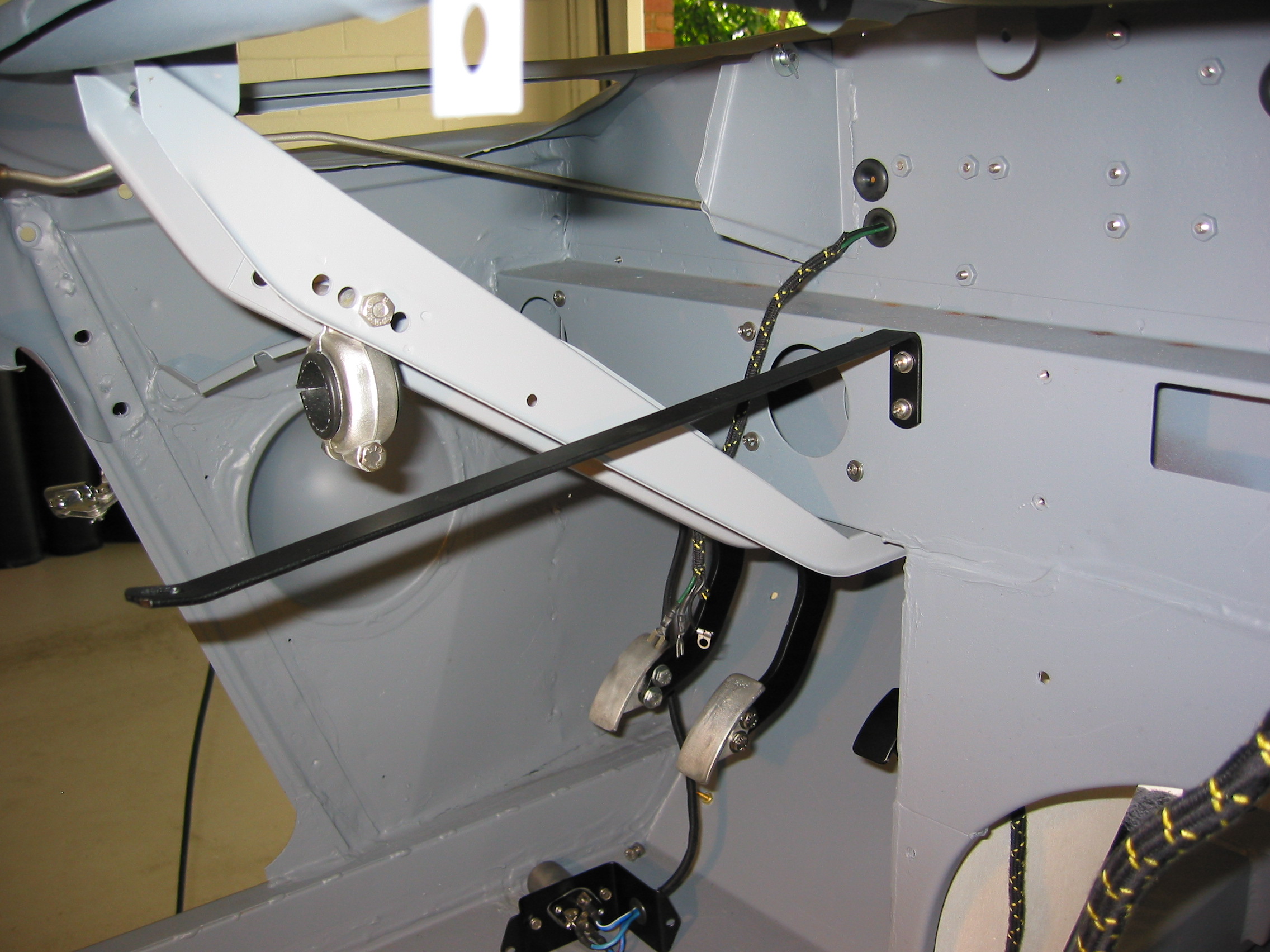
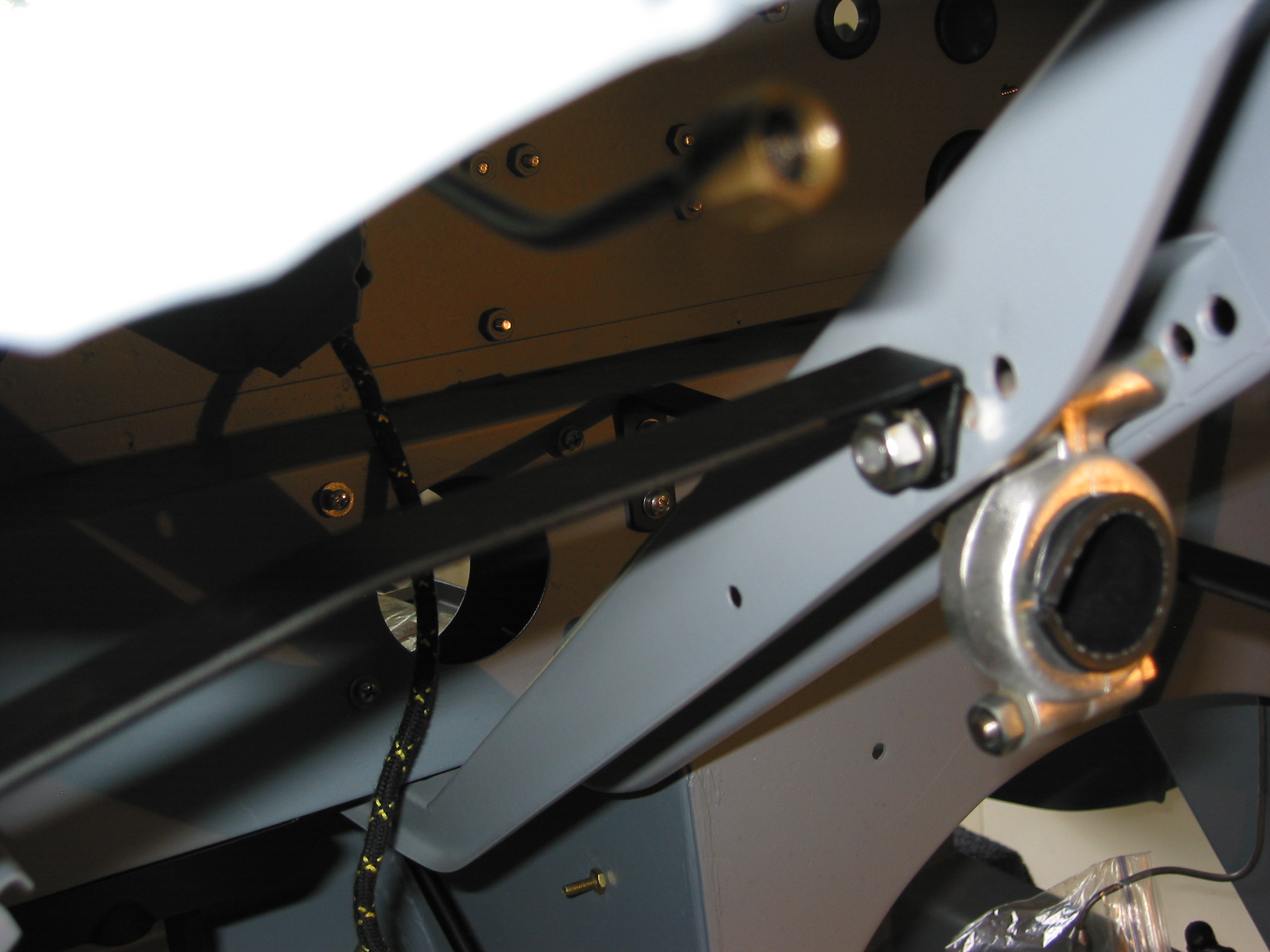
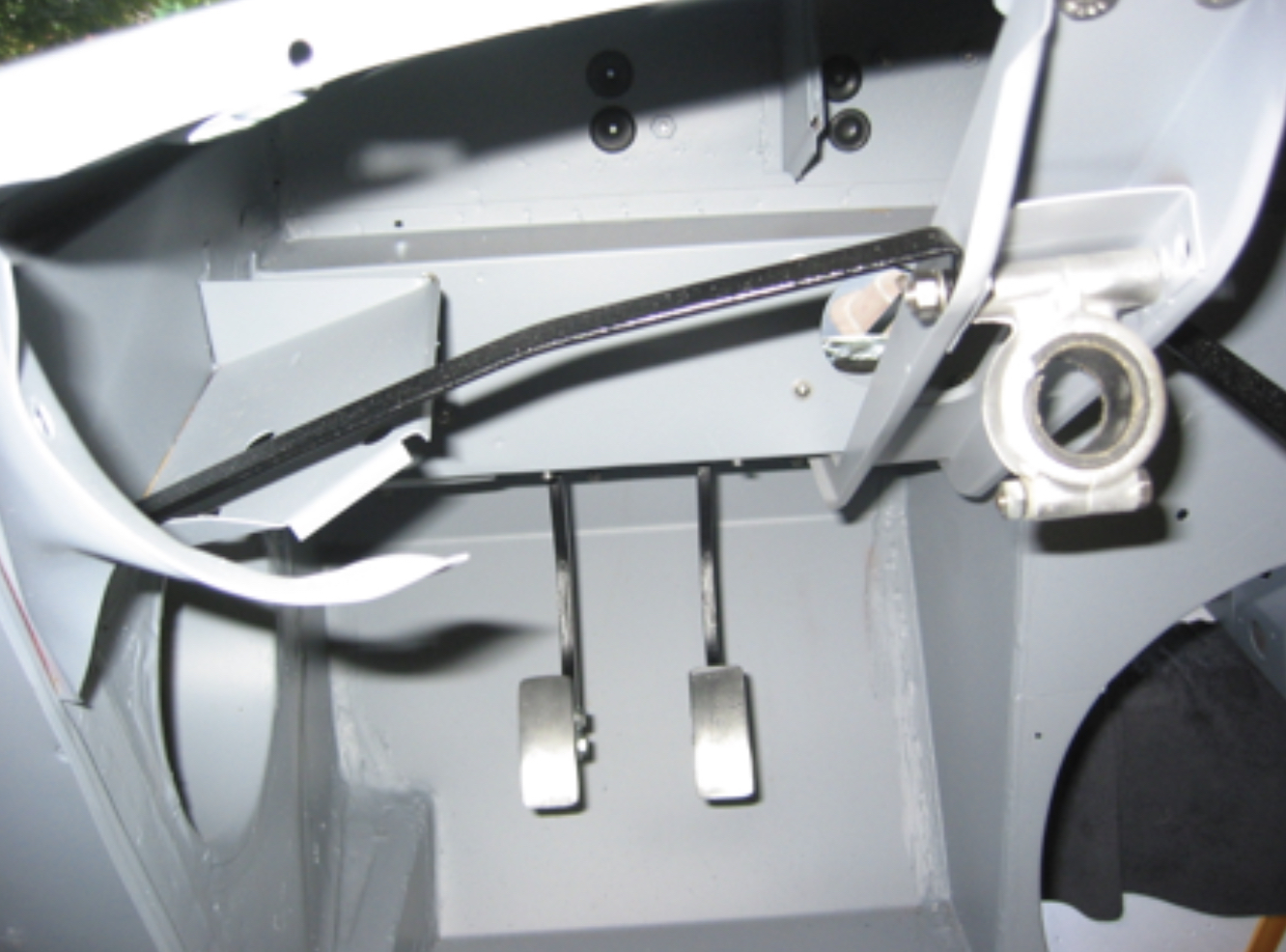
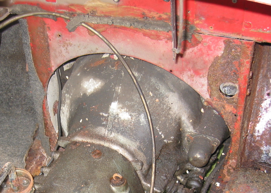
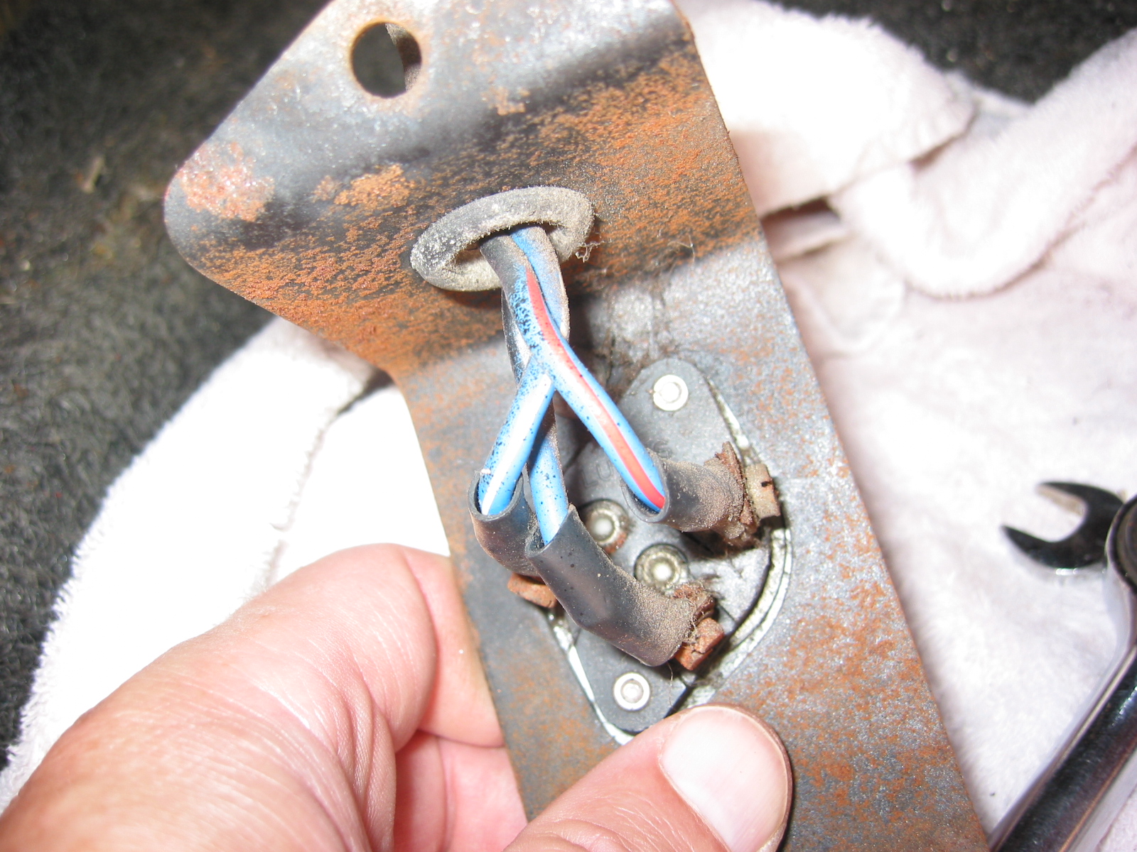
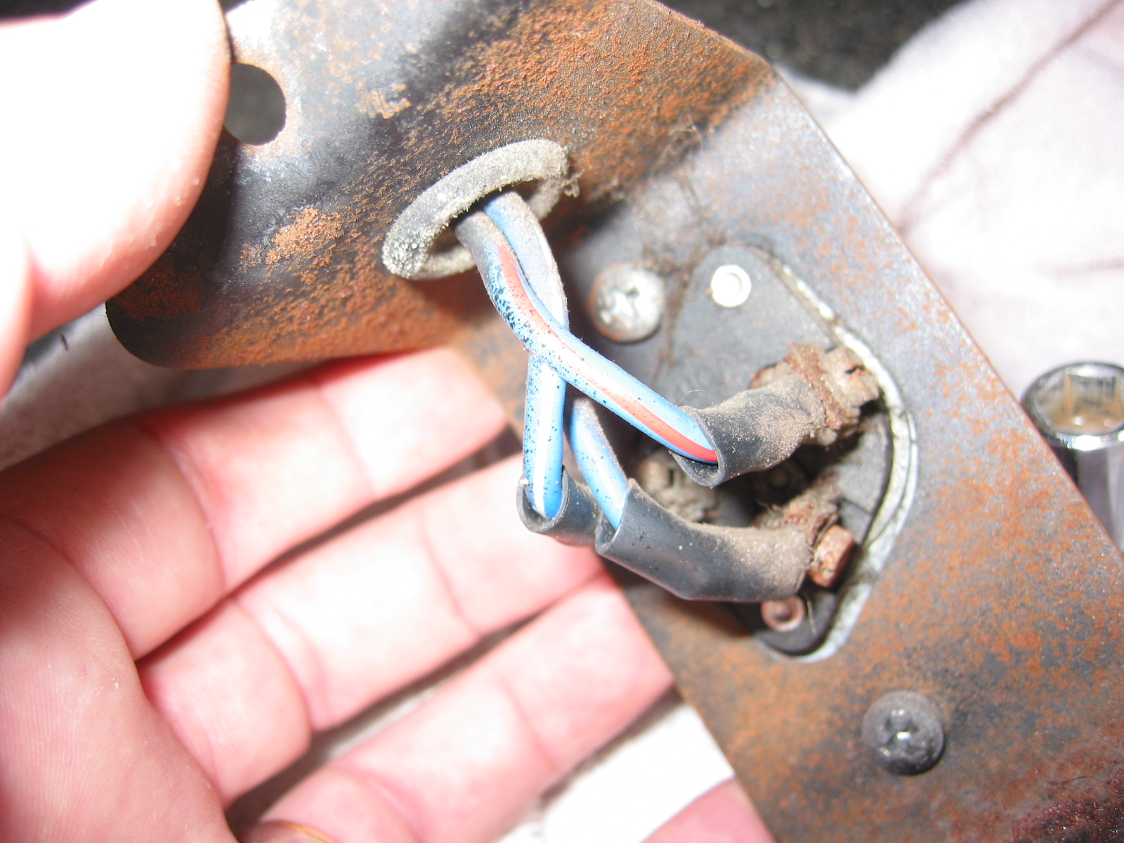
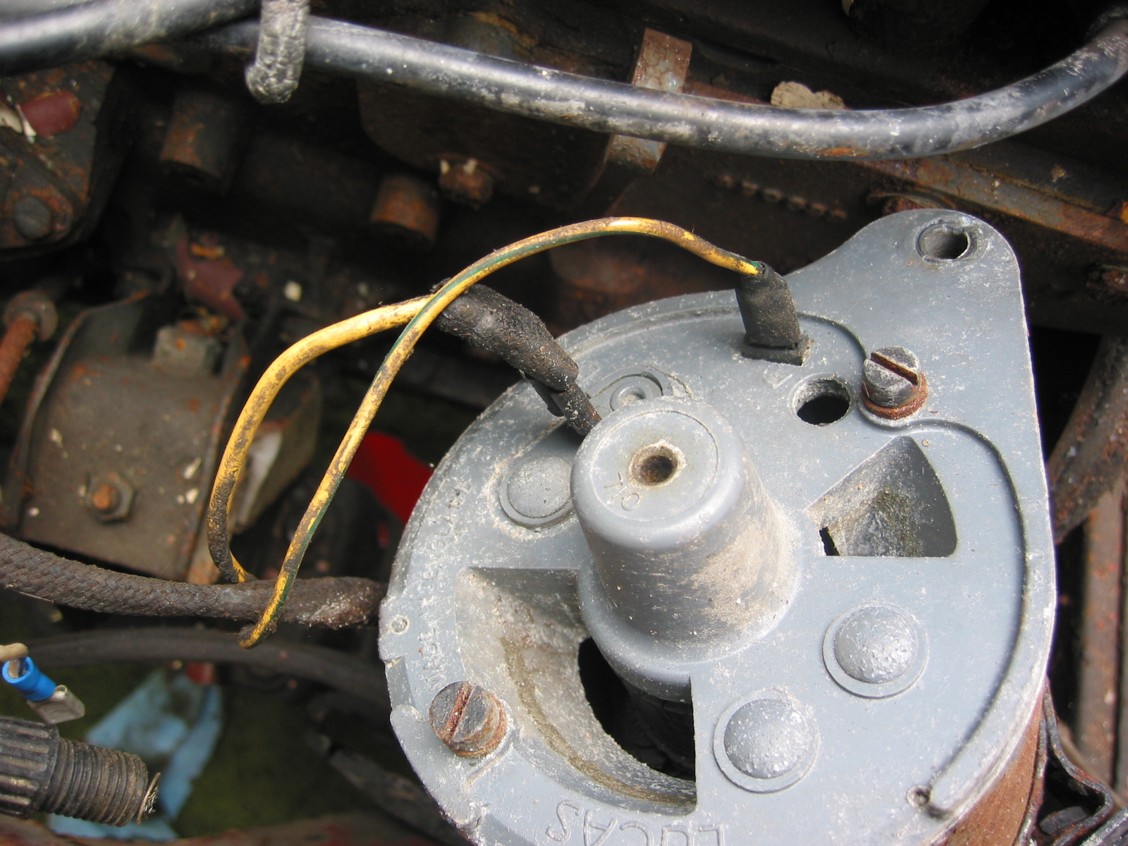
The two windscreen washer jets were installed on the shroud (would have been much easier to do before the shroud was put in place!) and connected with rubber tubing to the reservoir in the parcel shelf. I had previously installed the wiper motor, crosshead and rack, but I now needed to bring the wheelbox assembly up through the front shroud and secure them in place with the rubber washer, chrome bezel and chrome nut. This was not a pleasant job with all the wiring and underdash components in place, but after some struggling the job was accomplished.
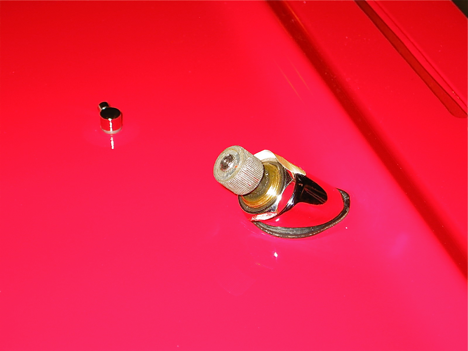
Wipers

Chapter 14 – Cleaning and Trial Fitting

August 26, 2003

Wiring 

Wiring Harness – Received the new wiring harness from British Wiring Inc. We ordered the main harness, horn wiring that we probably won’t need, light pigtails and the stator tube wiring. Everything looked good. Also ordered a special pliers for pushing the wiring bullet connectors into the rubber joints which will prove to be a real time saver.

After taking the harness through the firewall, the major components were separated to go down the two sides of the car. 

Flasher – First connected the three wires to the flasher – green, light green, and green/brown. 

Wiper Harness – Then connected the wiper harness with connectors and fed it through the firewall – black, black/green, and green. 

Dimmer Switch – The wires for the dimmer switch were then connected and fed through the top of the footbox and connected to the switch – blue/red, light blue, and blue/white.

Fuse Panel – Wiring was then connected from the harness to the fuse box. Three white wires to the lower left terminal; one heavy brown wire to the top left terminal; two brown/green wires to the upper right terminal; and five green wires to the lower right terminals.

Throttle Switch – The white and white/purple wires intended for the throttle switch will not be used so rubber connectors were placed on the ends to avoid contact with metal. The wires were tucked below the fuse box.

Boot Harness Extension – Six wires were then connected from the firewall harness to the harness that goes to the fuel pump and boot for the lights. The harness runs down the footbox insulation panel with two clips. The harness was clipped to the master cylinder box and then taken through the welded clip on the wheel well. 

Flasher Relay Box – Wires on the left side will then be connected to the flasher relay box including a black ground wire at the base of the box. 

Lights and Horns – The wires were routed to the front of the superstructure for the lights and the horns.

Voltage Regulator Box and Brake Light Switch – The harness was also routed down the right side, by the voltage box and down the right side to the brake light switch.

Wiring 3

Wiring 1

Wiring Fuse Block 2

Wiring 6

Wiring 8

Wiring 9

Wiring 12

September 9, 2003

Heater Vent Doors – Installed the left and right heater outlet vent door assemblies.

Air Vents 1

Air Vents 2

Bump Boxes – Installed painted bump boxes. Secured threaded horn mounting plates.

Bump Box Painted 1

Steering column bracket tapped plate

Parcel Tray and Fascia Brackets – Installed parcel tray support bracket and fascia support brace.

Parcel Tray Brace

Fascia Brace

Steering Column Steady Bracket – Installed steering column steady bracket, but unclear about which windscreen post hole it should mount to – will check it out later.

Steering support Brace

Steering Column Steady Bracket 2

Bonnet Prop Rod  and Brake Reservoir Brackets – Installed bonnet prop rod bracket, pivot, and the brake reservoir mounting bracket.

Brake Reservoir Bracket

Bonnet Rod Bracket

Bonnet safety catch and prop rod bracket

Bonnet Latch Bracket and Release Mechanism – Assembled and installed the bonnet latch/release mechanism.

Bonnet Catch painted 4

Bonnet Catch painted 3

Bonnet Catch painted 2

September 13, 2003

Wiring Continued

Battery Cable – Installed the battery cable ordered from British Car Specialists. The cable set was expensive, but of high quality. Installed rubber grommets in boot kick panel wall. Clip 1 was attached to the right bump box (Should install the cable on the box before it is mounted on the body.) Clip 2 was attached to the kick panel above the shock mounting bracket. The cable was then routed inside of the right frame rail.

Battery Cable 2

Battery Cable 1

Battery Cable 3

Battery Cable 4

Clip 3 and clip 4 were located at the back of the cruciform. Clip 5 was located at the front of the cruciform near the gearbox mounting bracket. Clip 6 was located on the frame rail about 6” from the ground cable mounting. Clip 7 was mounted on the right footbox wall with the cable directed to the right terminal of the starter solenoid. The Cable from the starter to the left terminal on the solenoid was then secured. The white/red stripe wire fastened to the small terminal on the solenoid. Three “cert” nuts need to be installed – two for the solenoid and one for the clip on the footbox.

Battery Cable 5

Battery Cable 6

Battery Cable 8

Battery Cable 9

Next, the rear lights harness was installed. Clip 1 was secured at the right upper fuel pump bracket. Clip 2 was secured on the kick panel to the left of the pump. Clip 3 was attached to the left bump box and the wiring was threaded through the boot wall. The green wire will connect to the fuel gauge sending unit. Metal tabs were fabricated from clips and mounted on the floorboard of the boot.

Single bullet connectors were used to join the main harness to the rear light harness and link the white/black wire, and the white/purple wire. The red wires were connected using a double rubber connector. Clips 3 and 4 were mounted to the rear rail. The long separate white/black wire was also routed through and it connected to the single screw terminal on the battery on/off switch. Black ground wires were connected to the screw on each clip.

Boot Wiring 1

Boot Wiring 2

Boot Wiring 3

Boot Wiring 6

Boot Wiring 4

Boot Wiring 5


Chapter 5 – Disassembly

June 29, 2002

Final Interior Dismantling

Gearbox tunnel and extension cover. Both were rusted badly and were discarded. I learned later as I was fitting new parts that I should not have violated the restorer’s rule: Never throw anything away until the project is complete!

Gearbox tunnel and extension cover

Fresh Air cover plate and screen on left (driver’s) side. Three self threading screws.

Parcel tray on passenger side. Four self tapping screws on the firewall. Three self tapping screws on the right side wall. One screw and nut into left side to hanging support bar. Then removed the parcel support bar with one screw and nut at top.

Parcel Tray Support brace.

Steering Wheel Shaft Blanking Plate on the right side. Note larger “painted washers” and self tapping screws. Felt gasket found on reverse side of the plate.

Steering Wheel Blanking Plate

Steering Wheel Shaft Blanking Plate Felt Gasket

Two Blanking Screws into captive nuts in firewall on passenger side that just fill holes similar to the driver’s side. These were not painted.

Large Wiring Harness Rubber Grommet in center of firewall. Then removed firewall tarpaper in center of firewall. Note the rubber insulation around the heater box hole and along the seam that would otherwise leak air.

Heat Insulation (tar paper) on firewall

Firewall Grommet

Heater Channel Opening

Center Panel Firewall “Tarpaper.” After removing the firewall “tarpaper” that is in three pieces I numbered the holes:

#1 – Bonnet release rod grommet

#2 – Blank Cover grommet

#3 – Grommet

#4 – Brake Line clip

#5 – Grommet

#6 – Grommet

#7 – Nut

#8 – Nut

#9 – Brake Line Clip

#10 – 1 Nut, 2 grommets Wiper motor

#11 – 2 Nuts

#12 – Nut

#13 – Nut

#14 – Nut

#15 – Nut

#16 – Main wiring harness to dash

#17 – Blank Cover Grommet

#18 – Nut

#19 – Nut

#20 – Nut

#21 – Grommet 

Left Panel Firewall “tarpaper”:

#22 – H2O temp. line

#23 – Oil line

#24 – Nut

Small Blanking Rubber Grommets under the heater opening in firewall. 

Blanking Rubber Grommets

Right Bonnet Hinge cotter pin and 4 washers. The thin washers go closest to the hinge. The nuts go to the inside of the bonnet.

Bonnet Hinge Fixing

Bonnet Hinge

Speedometer Cable at “L” junction to the gearbox.

Speedometer Cable to Gearbox

Clutch Pedal from pedal bar – two nuts. The nuts go to the right side. Removed the Brake pedal from pedal bar – two nuts with nuts to the right side. I noticed at this point that some primatively cut spacers had been added to the pedals for a short-legged driver!

Clutch Pedal

Clutch Pedal Spacer

Pedal Spacers

Floor Dip Switch with two bolts to the fixed nuts in floor. 3 wires: red/blue, blue/white, all blue.

Dip Switch Wiring and Bracket

Dip Switch

Heater Vents on both driver and passenger side below dash. Four self tapping screws in each

Heater Fresh Air Vent Door

July 2, 2002

Engine

Fan and fan belt – Loosened 4 bolts and washers and removed the fan and fan belt.

Fan and Fan Belt

Wiring to the coil –  CB Terminal – White with black stripe from/to the distributor body and white with black stripe from harness that goes to the generator. SW Terminal – Large solid white wire from harness to generator.

Coil Wiring

Generator – Removed 2 bolts and nuts and adjusting bracket with self-locking nut. F Terminal – yellow/green stripe wire from harness. D Terminal – Large solid yellow wire connected to large spade.

Dynamo – Generator

Generator Adjustable Mounting Bracket

Generator Wiring

Distributor –  Removed two 7/16” bolts – note position of distributor and vacuum advance. Numbered each wire to the correct cylinder. Disconnect vacuum line and oil feed line to the tachometer drive.

Distributor Wiring

Distributor

Distributor Cap

Distributor Mounting Clamp

Oil Filter –  Removed two large bolts to the engine block.

Oil Filter Mount

Oil Filter

Starter and Solenoid  Disconnected solenoid to starter lead cable. Loosen two 9/16” bolts accessed through the interior bulkhead and under car.

Starter

Starter Solenoid

Starter Solenoid Wiring

Starter Cover

Engine mounts – Removed 4 bolts from right front to frame. Then removed left side.

Engine to frame Mount

Ground strap –  Disconnected the strap from the frame.

Oil pressure line –  Disconnected the line at top union near intake manifold.

Oil Pressure Line Disconnect

Breather pipe –  Disconnected the pipe at the “T” junction on the rocker cover.

Breather Pipe Disconnect