Odds and Ends
This post covers a number of different and varied topics and they are presented in no particular order.
The Bugeye Restoration Video Episode Seventy-nine covers the full range of items addressed in this post: https://vimeo.com/996056168/94d2be9bab?share=copy
The long list of subjects covered by this video is detailed below:
0:00 – Bonnet rubber buffer installation
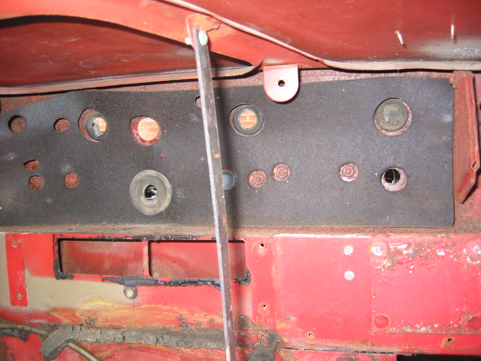
0:12 – Firewall rubber grommet installation
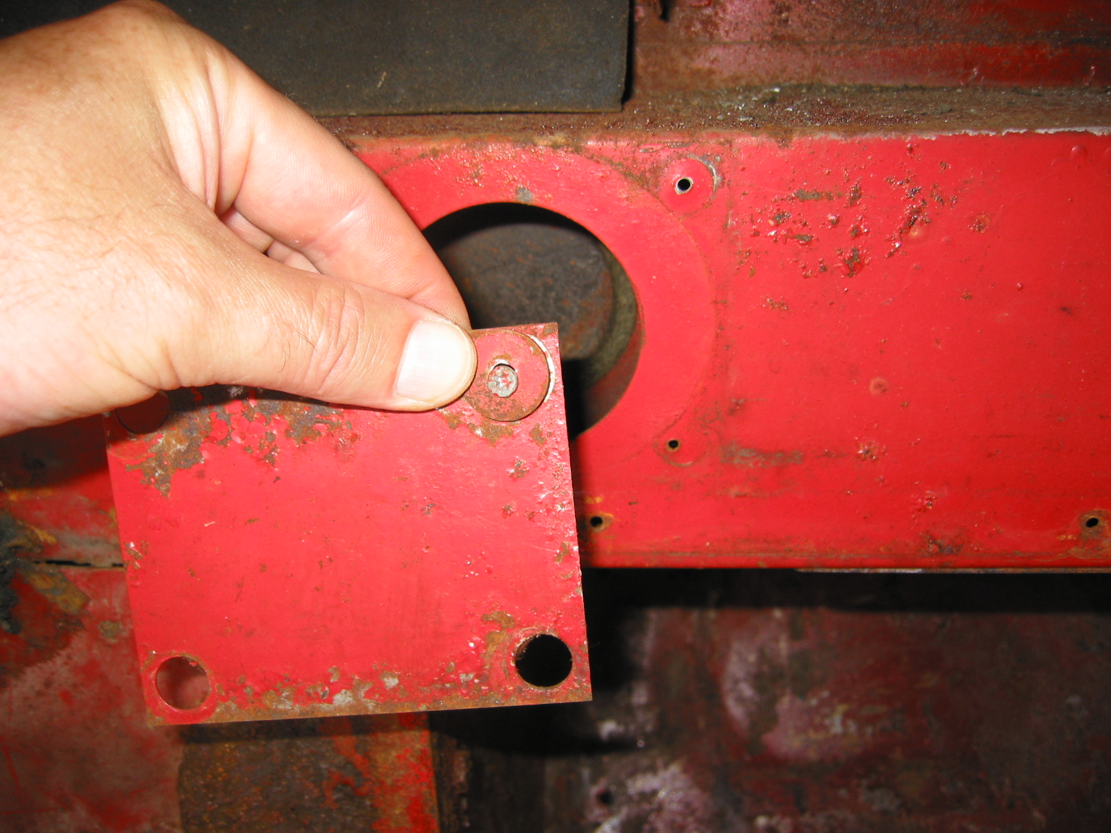
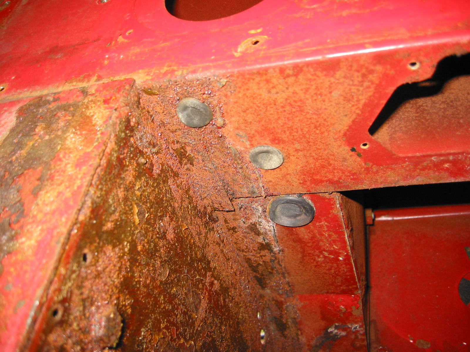
0:17 – Jacking point rubber plug
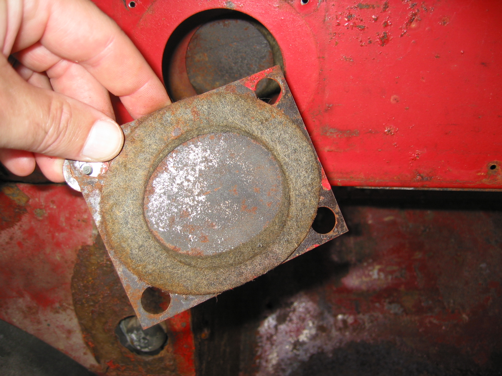
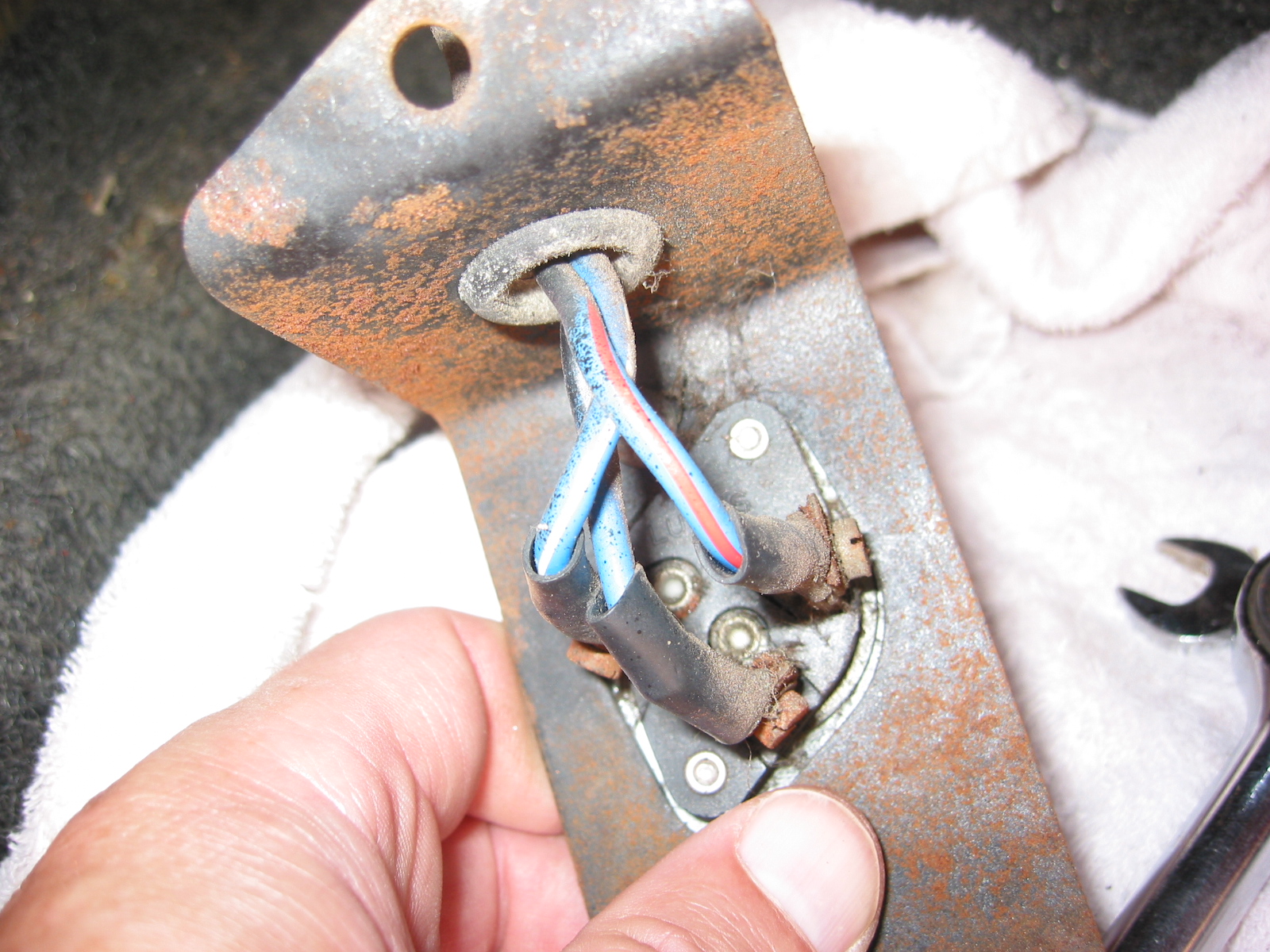
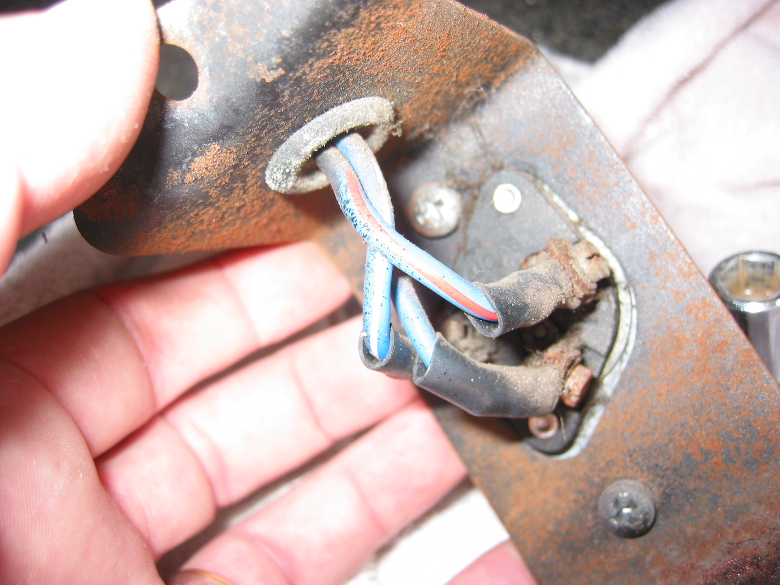
0:24 – RH footbox steering shaft blanking grommet
0:45 – Brake pipes installation completed
2:25 – Power distribution fuse box installation
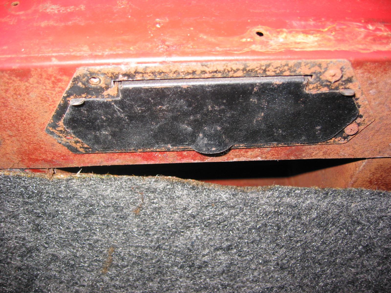
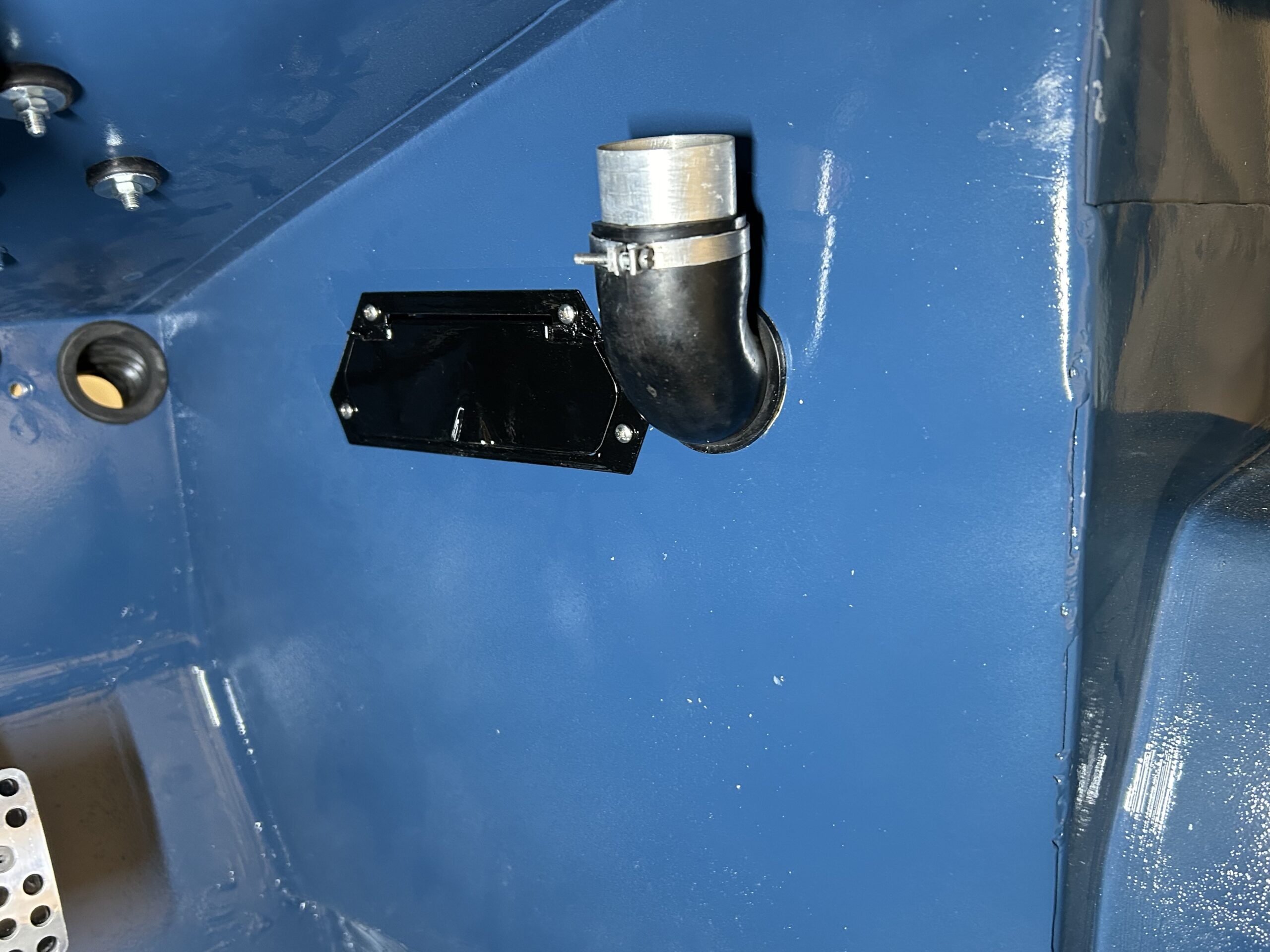
2:50 – Slave cylinder access rubber plug installation
3:18 – Interior footbox sill rubber plugs installation
3:40 – Windscreen spray jets installation
4:15 – Windscreen washer reservoir and holder installation
4:40 – Windscreen washer hose installation
5:30 – Wiper rack installation
5:48 – Wiper motor installed
6:18 – Firewall aluminum heat insulation installation
6:52 – Anti-rattle rubber pad for wiper rack
8:03 – Wiper motor installed again
9:40 – Fuel filler pipe seal installation
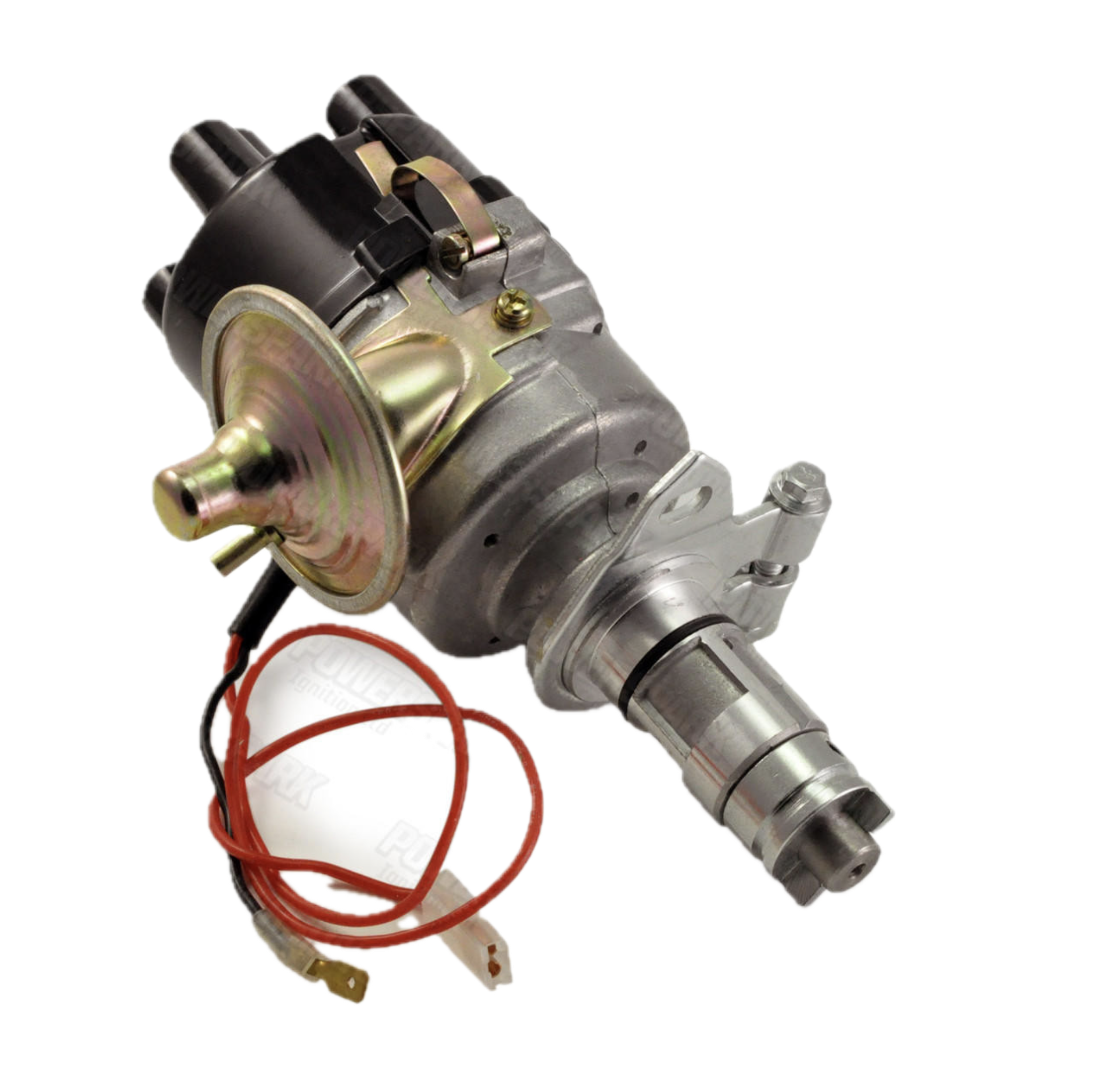
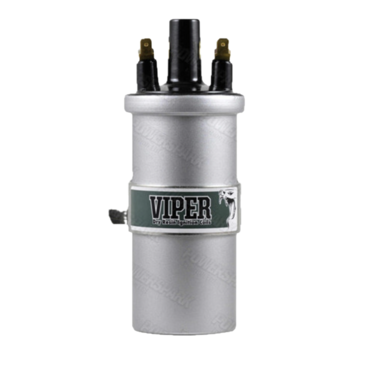
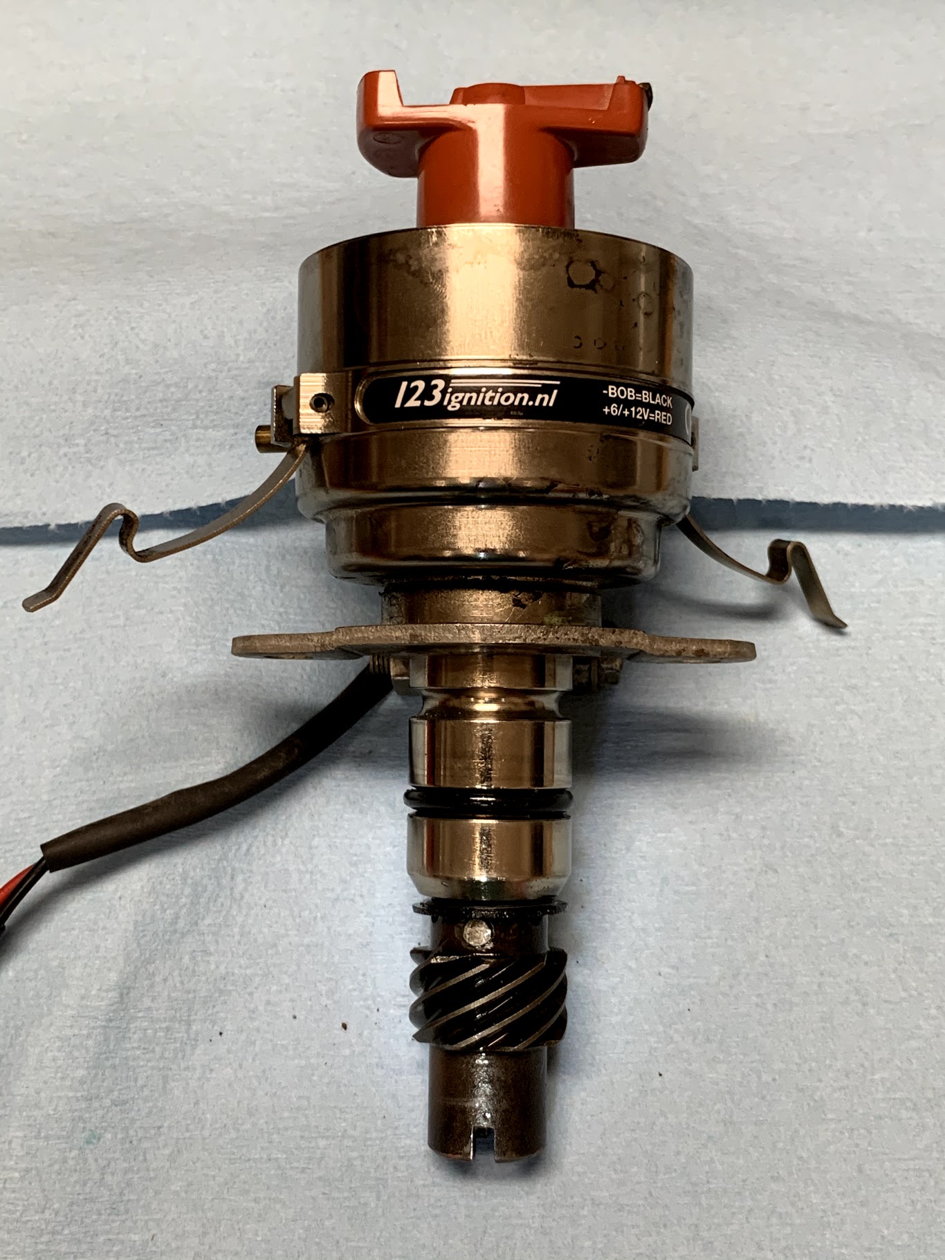
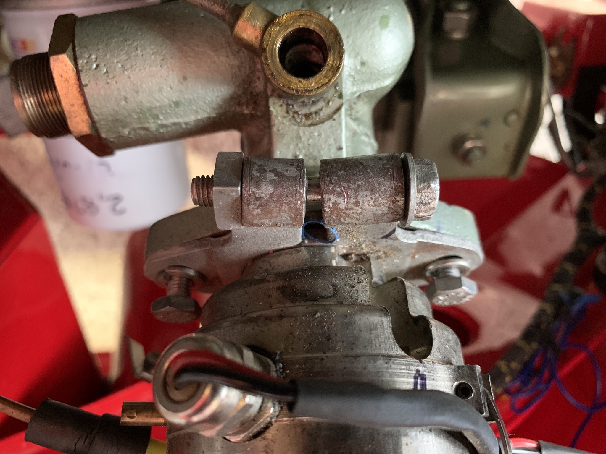
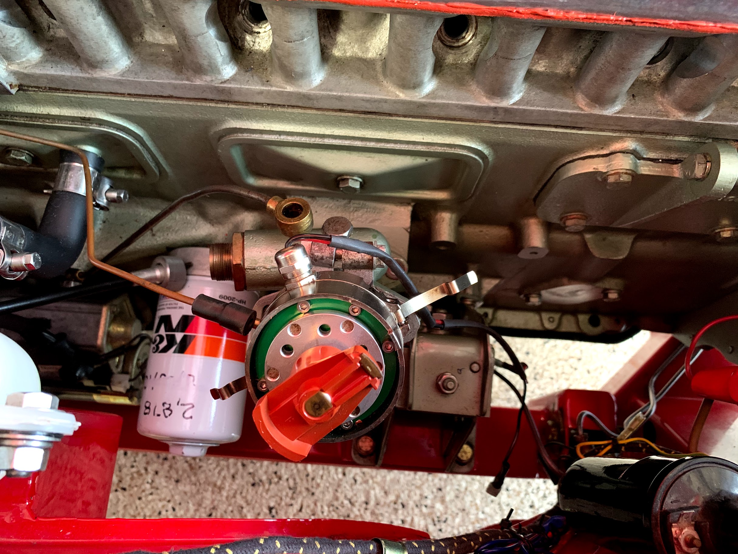
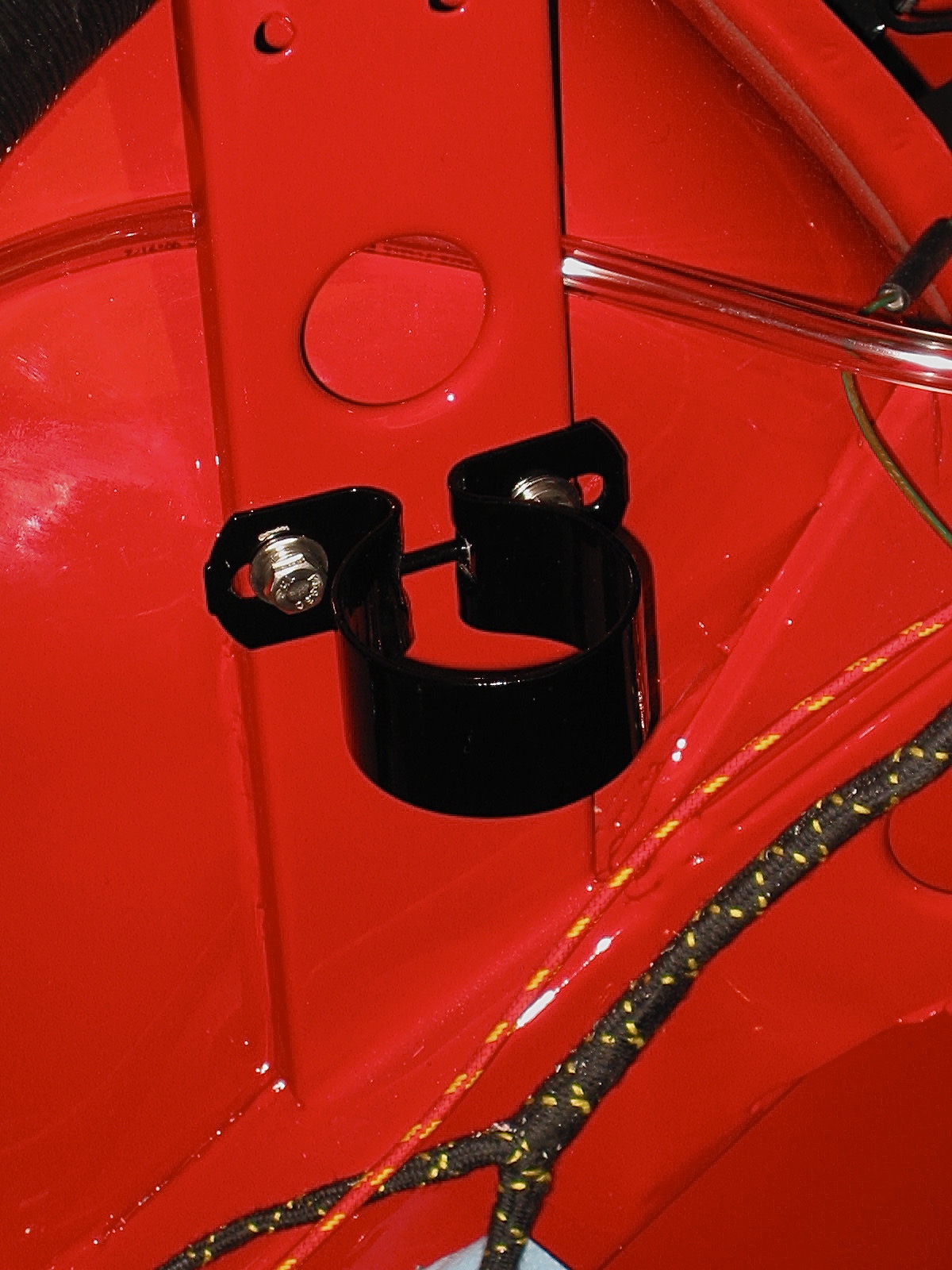
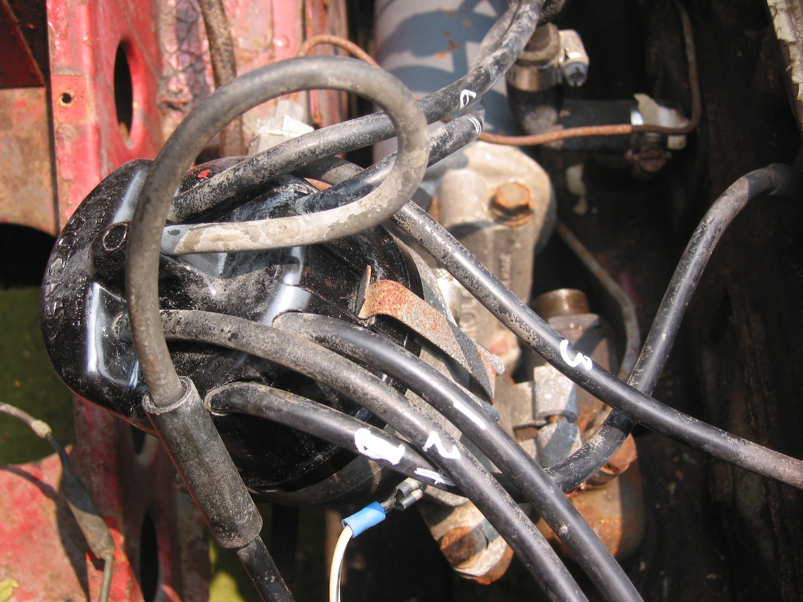
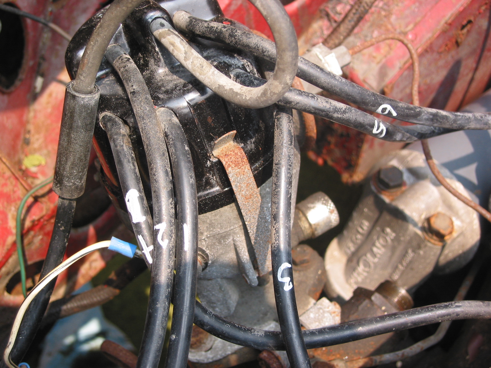
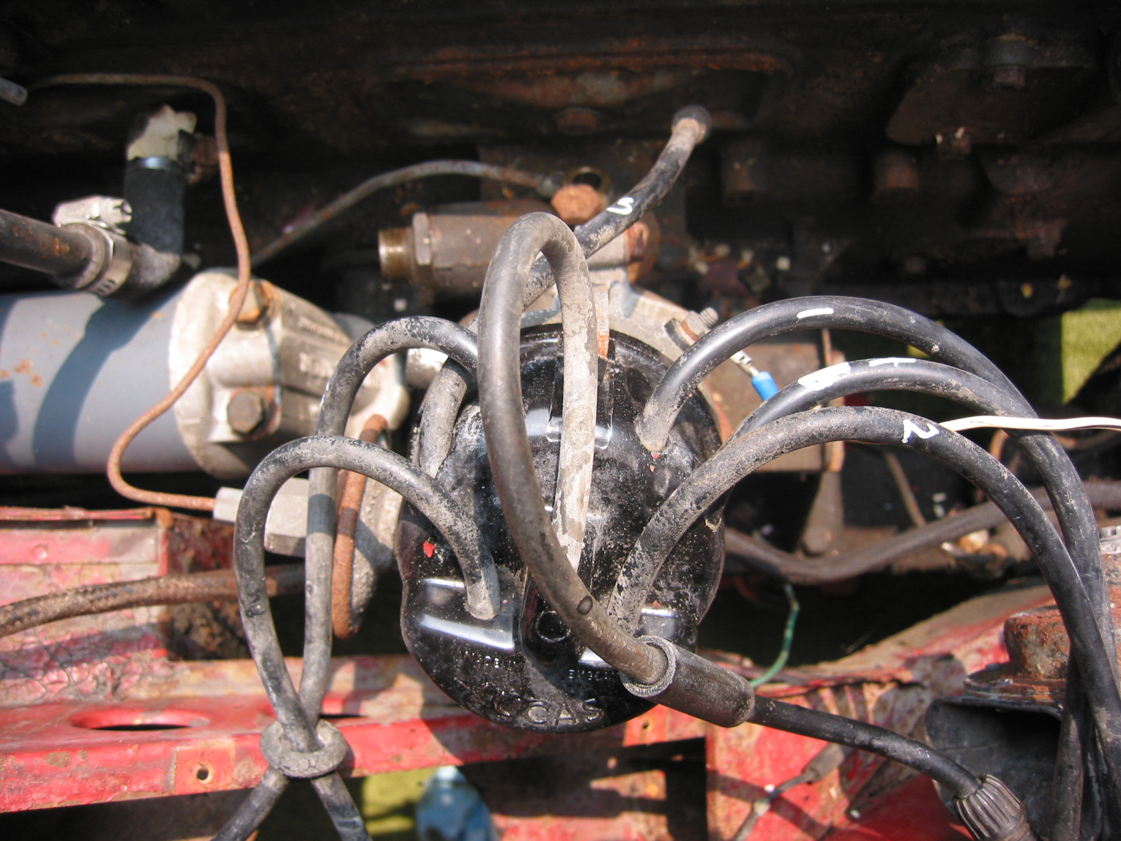
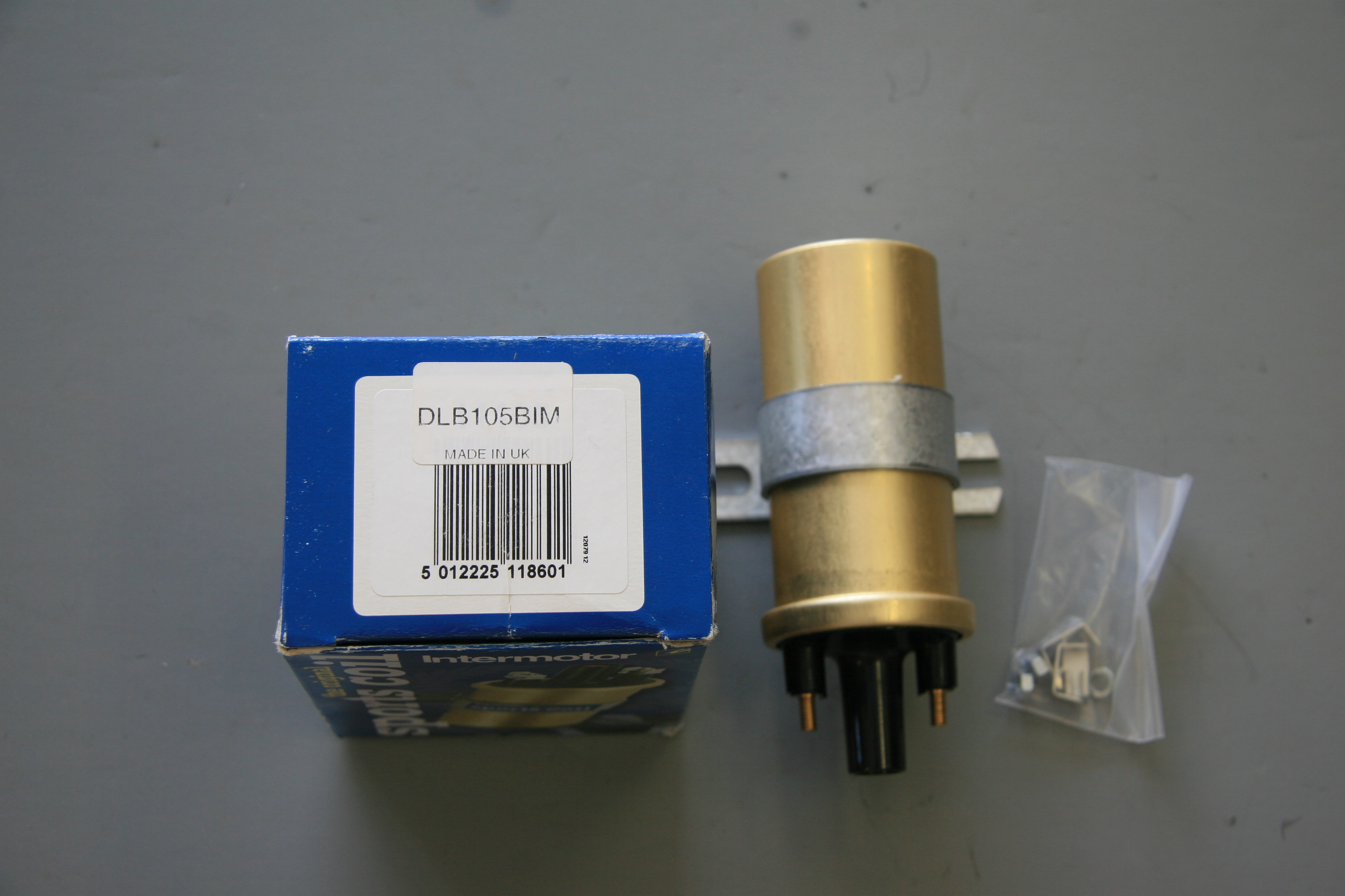
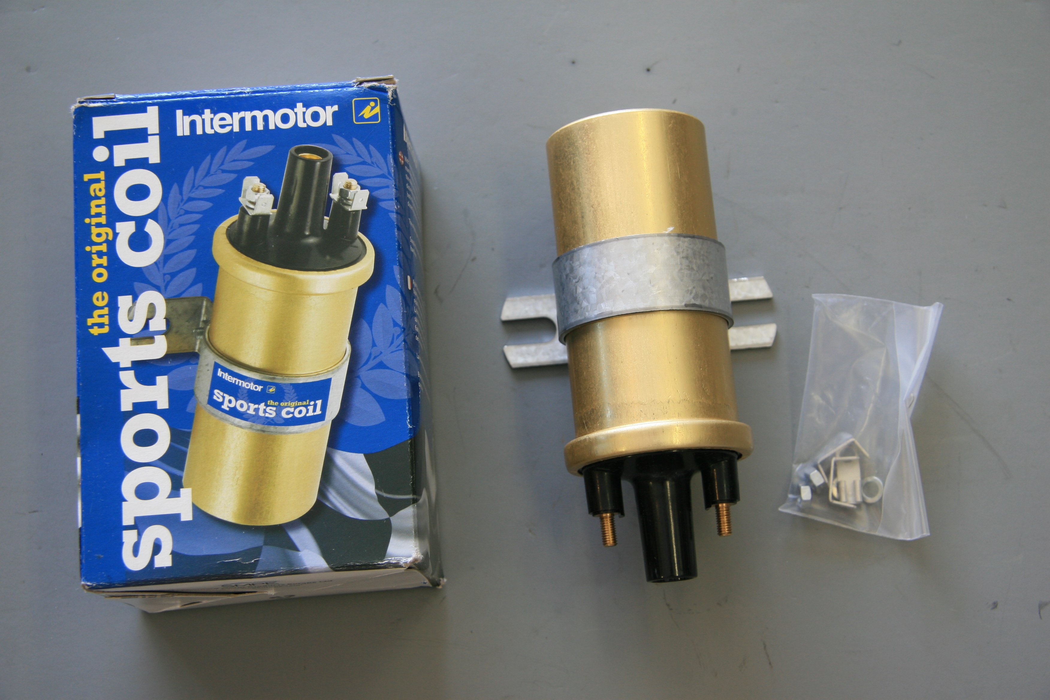
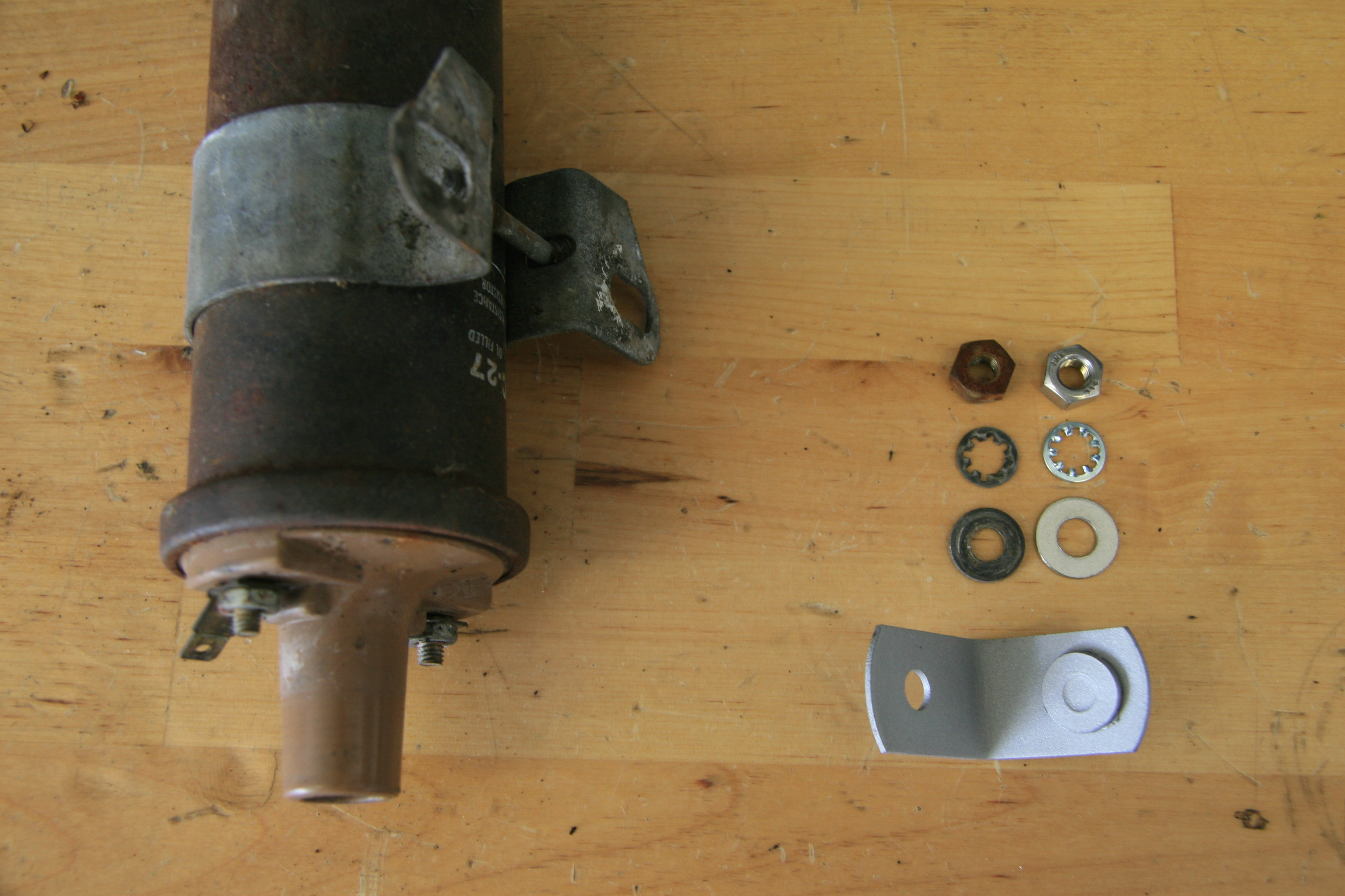
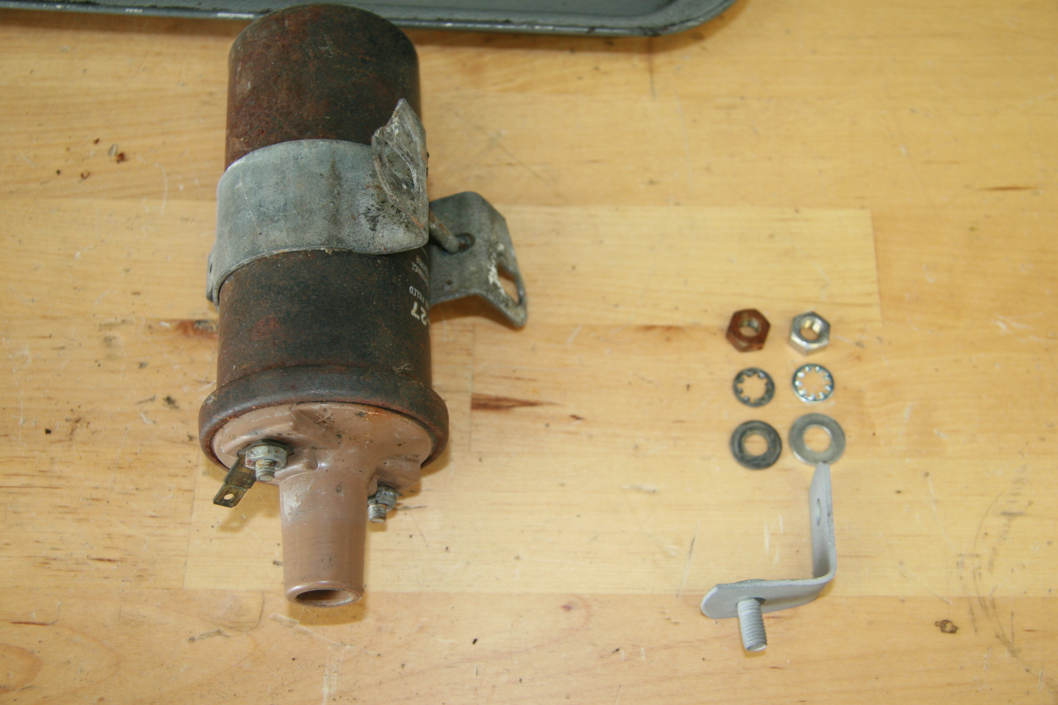
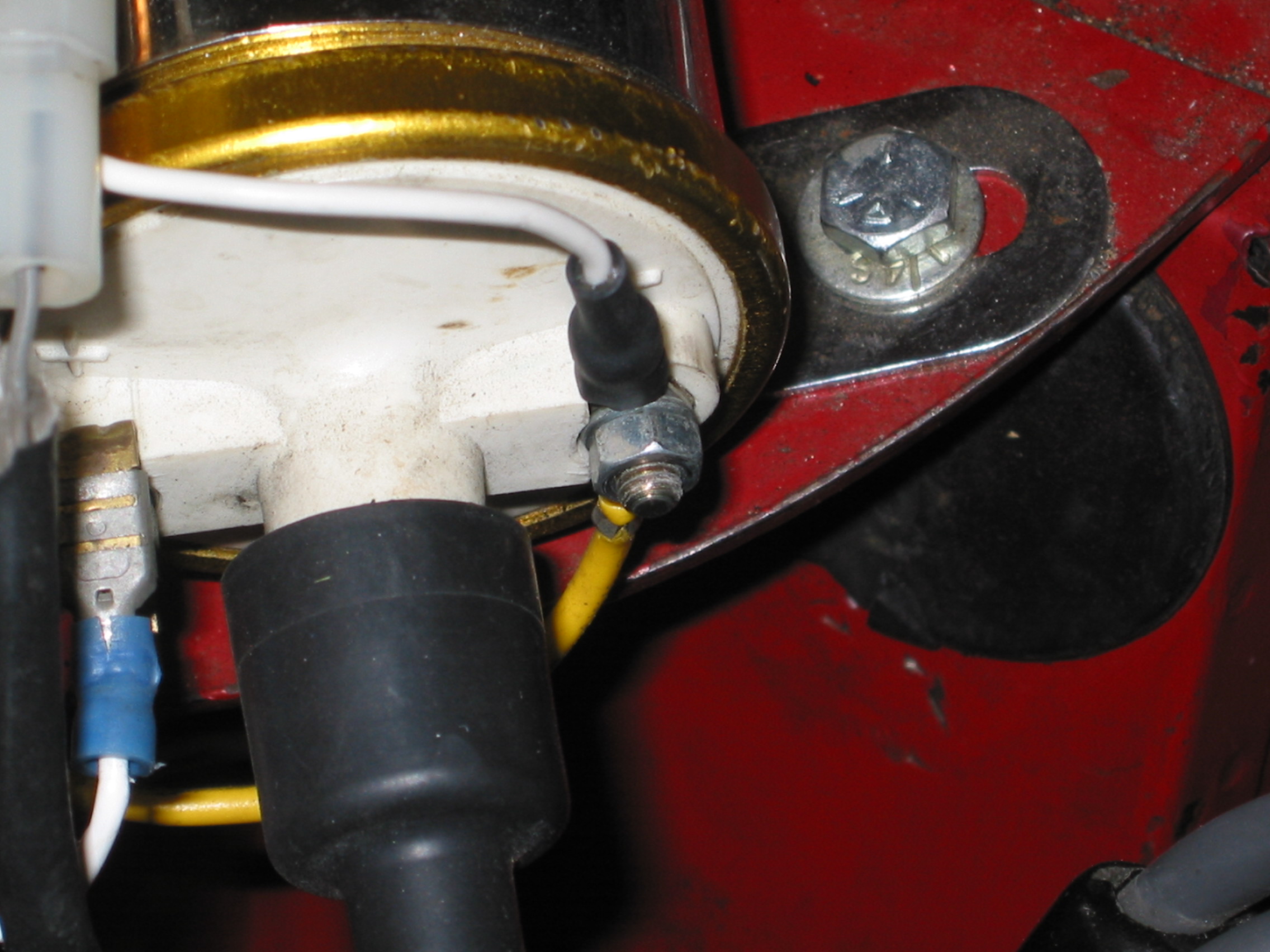
10:28 – Viper ignition coil installation
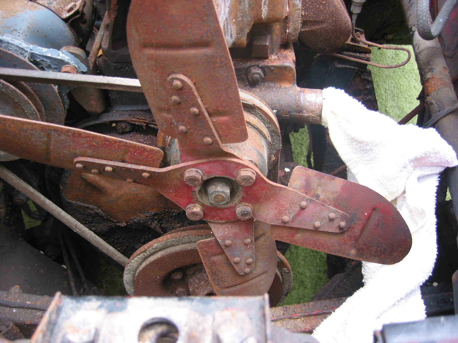
10:40 – Fan blower and heater box installation
12:59 – RH radiator brace and air duct installation
13:25 – LH radiator brace installation
13:40 – Demister vents installation
14:18 – Heater vent hinged doors installation
14:47 – Lift-a-dot fastener installation
15:55 – Tenax and turnbuckle fastener installation
18:06 – Self-tapping lift-a-dot fastener installation
Bits and Bobs
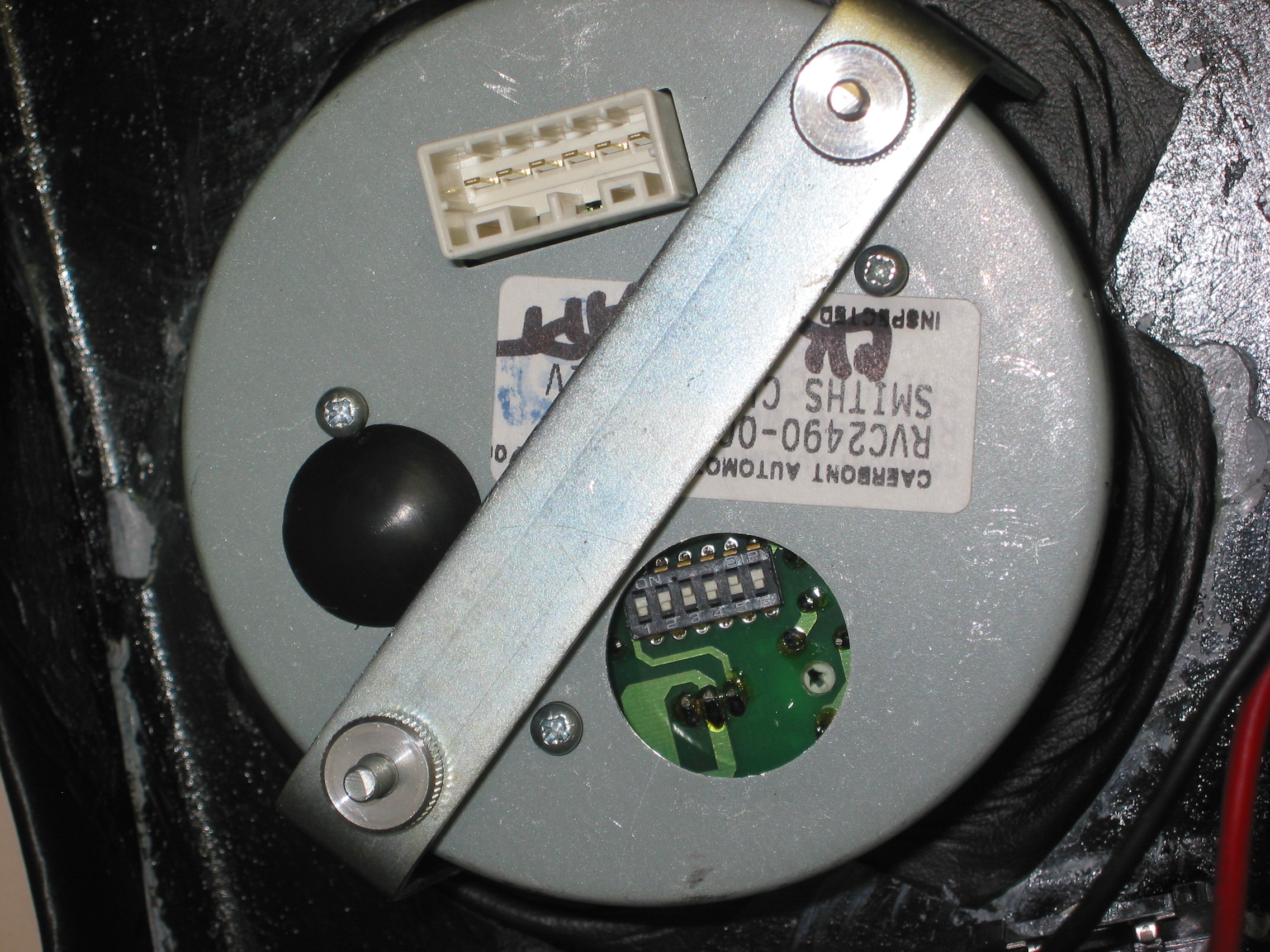
Demister Elbows. We installed a few more items on the car. The demister elbows were a couple of easy items to install.We also installed the demister hose on the RH passenger side of the car just to check fit with the windscreen wiper controller.
Demister elbow
The coolant overflow tank was the next item to mount on the car. It is located on the LH radiator brace.
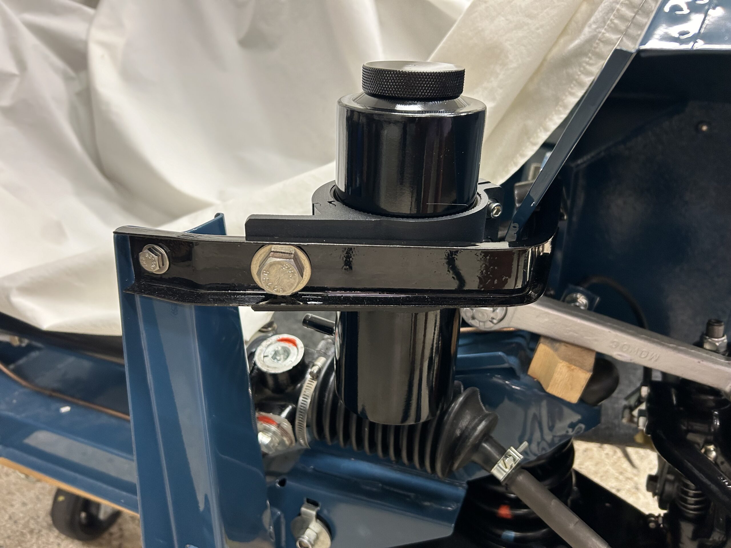
Coolant Overflow Tank
We were going to paint the bottle cap a color to signify that the container was for coolant and not a oil catch can, but we found this little sticker to go on the cap that will work just fine.
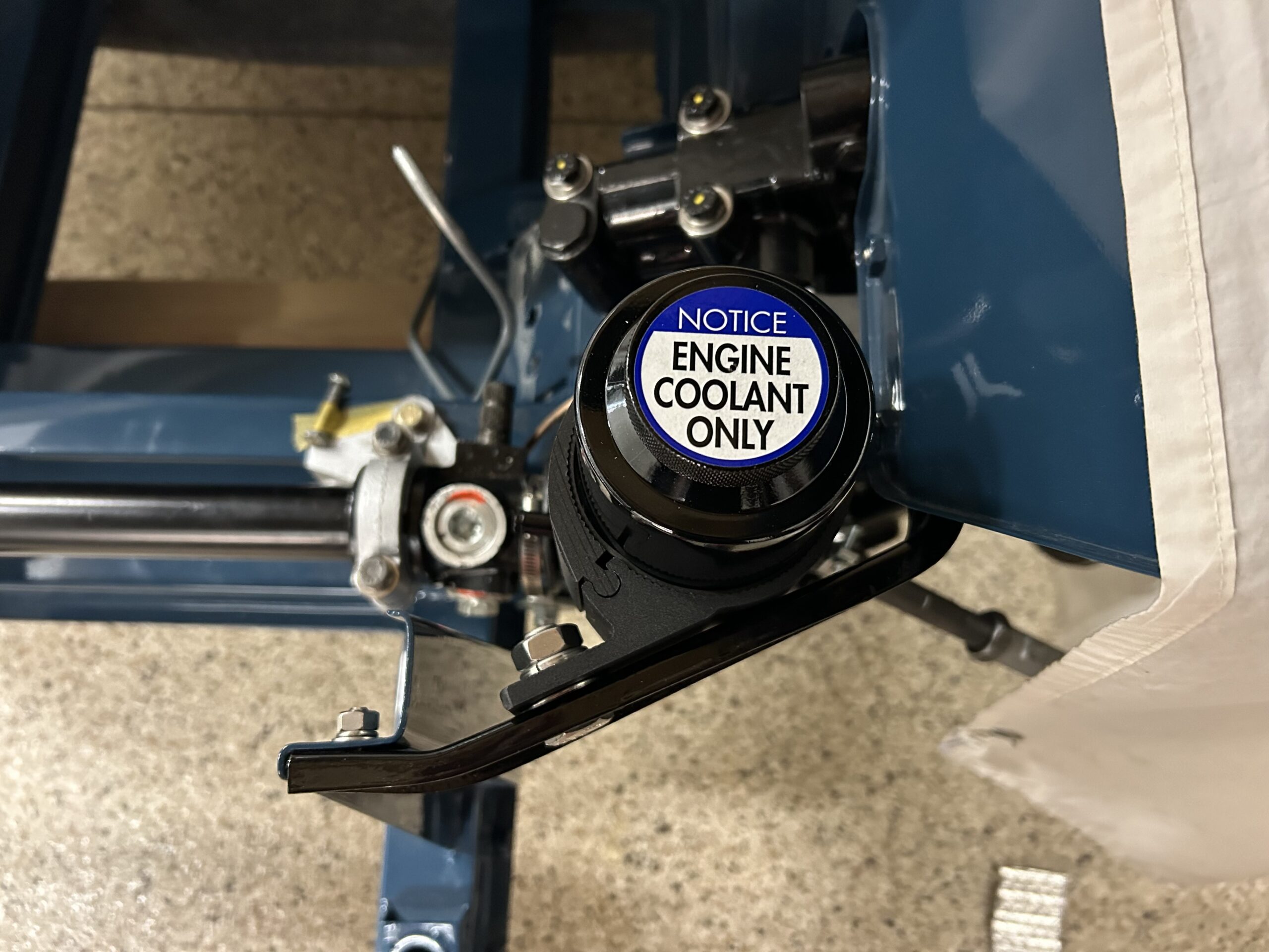
Coolant cap decal
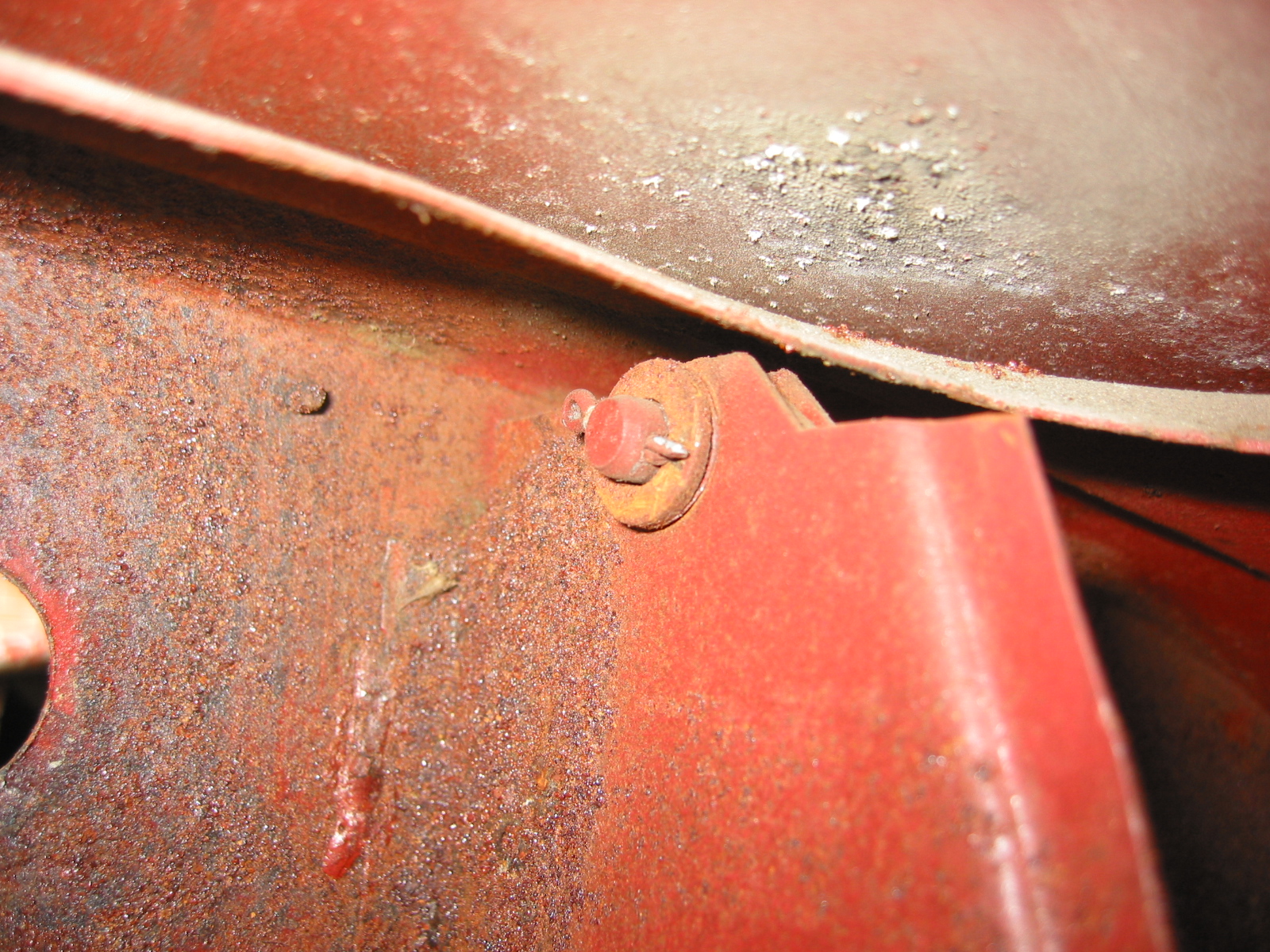
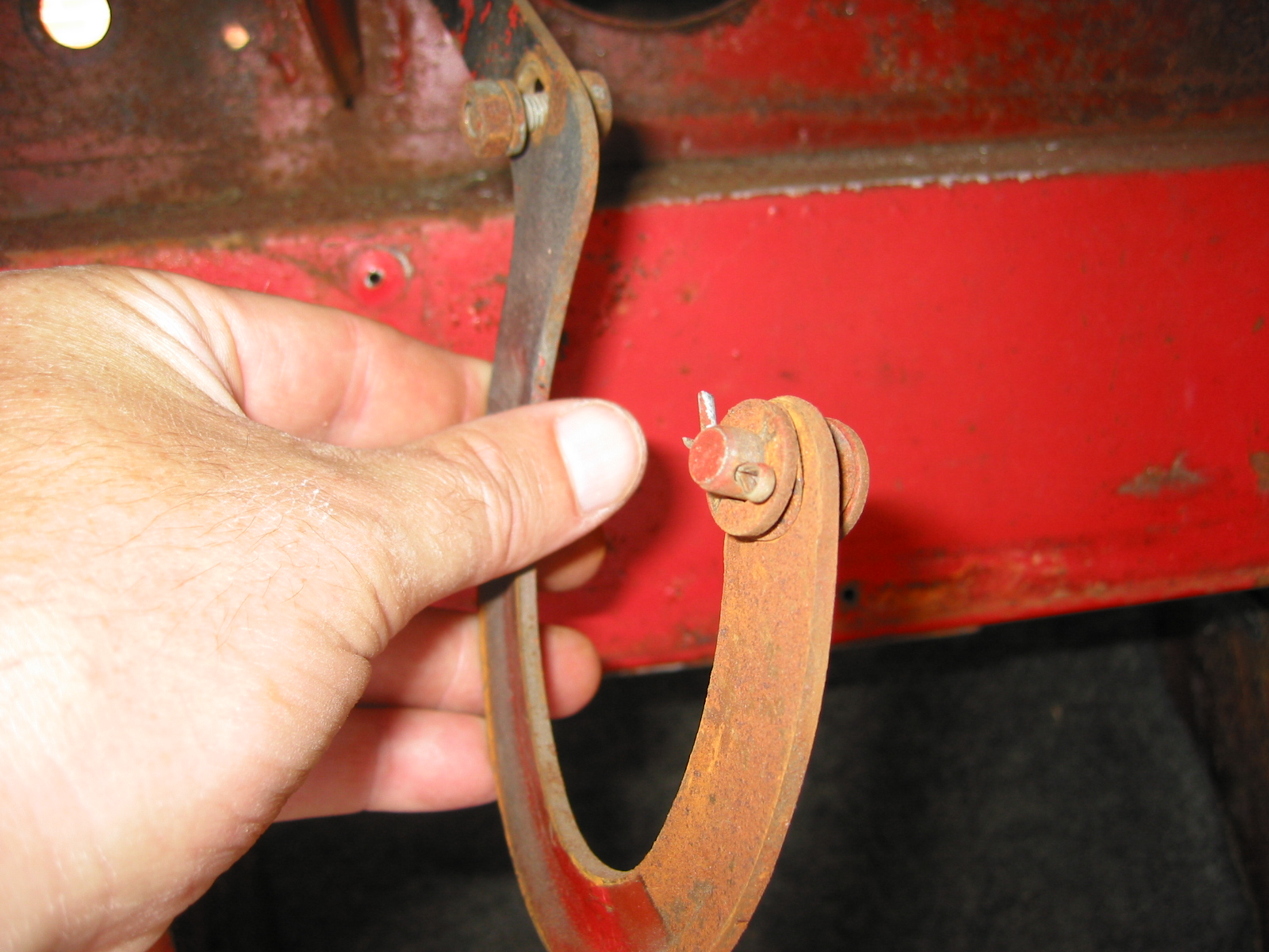
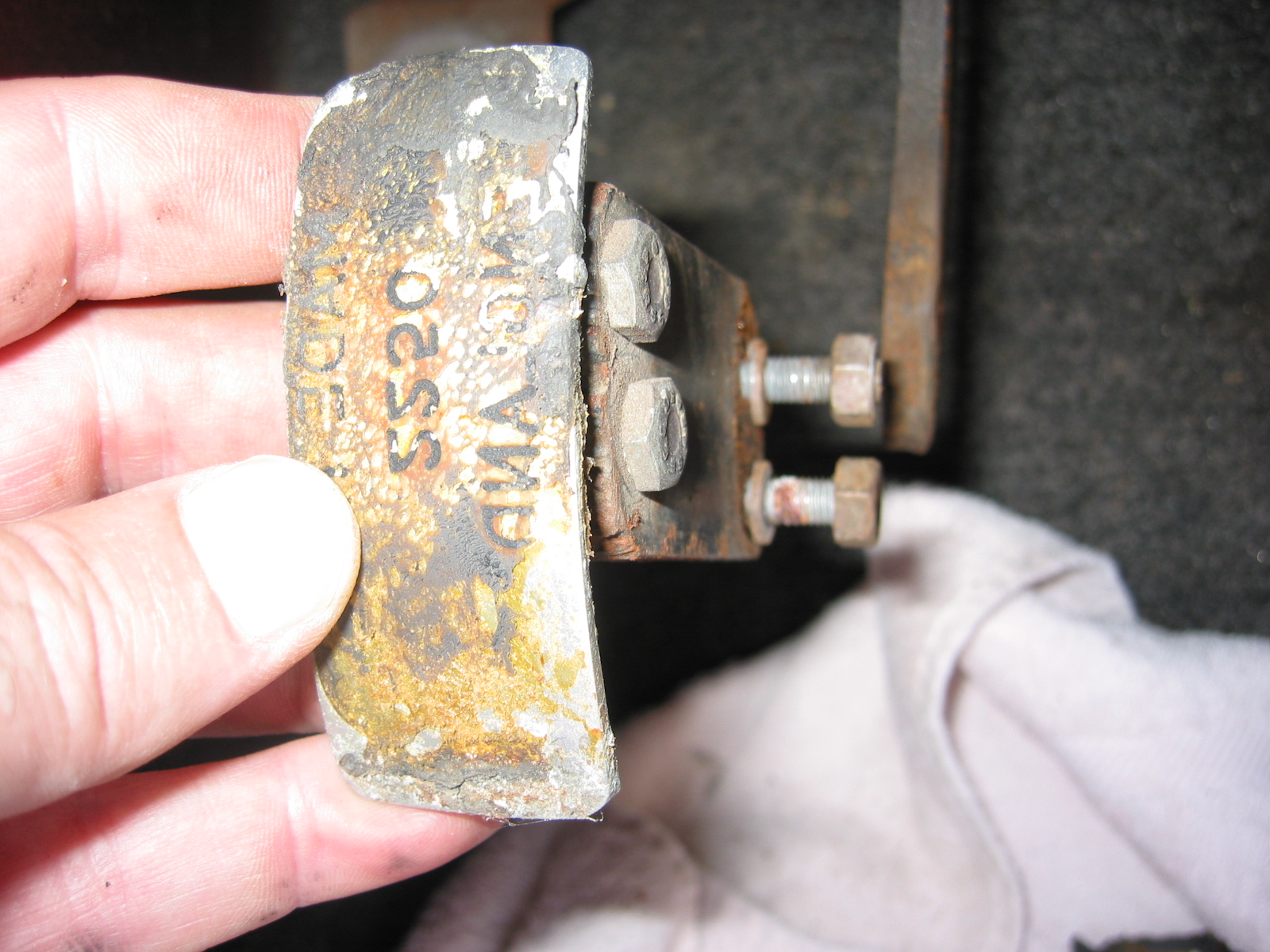
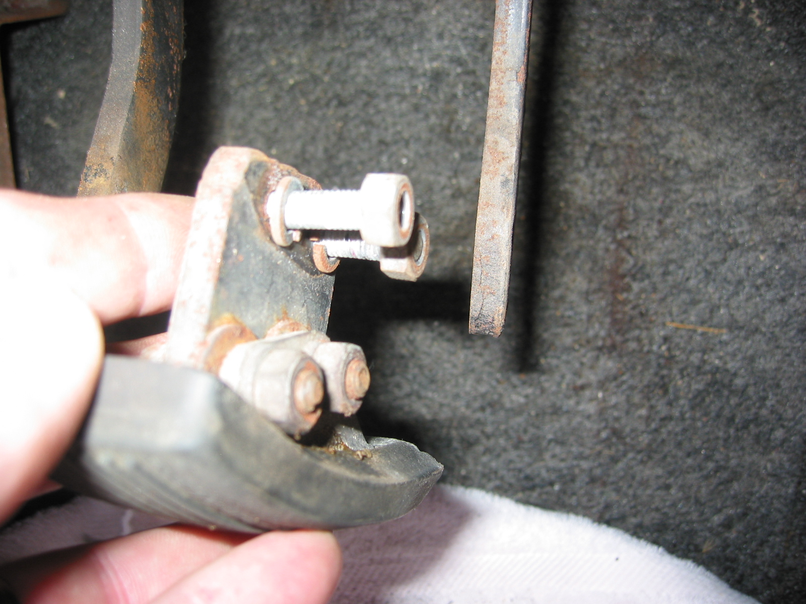
Then we added the bonnet rubber buffers. These buffers sit on aluminum blocks and are secured to the car with one #10 -32 x 1/2″ machine screws with washers. There is also a steel bushing or spacer inside the rubber buffer to keep it from compressing too much.
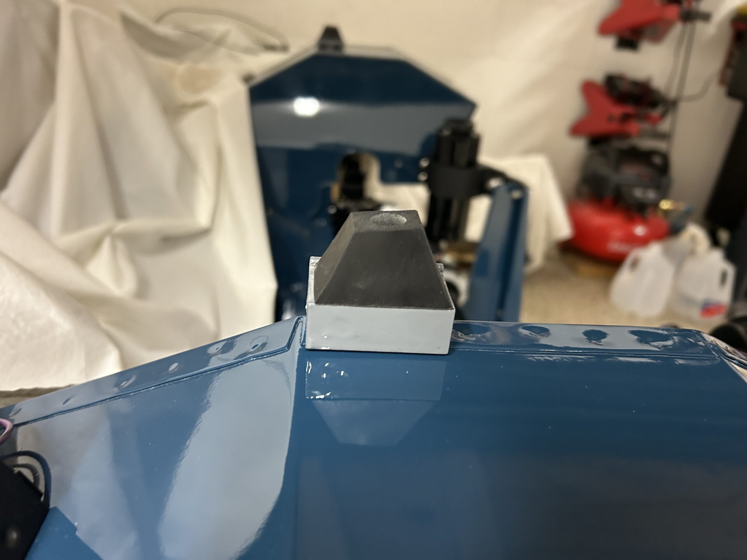
Bonnet Rubber Buffers
We then installed our fancy battery box sourced from Speedwell Engineering. A further explanation of the box and the installation process may be seen in a post made under the “Personalizations” category: https://valvechatter.com/?p=14483.
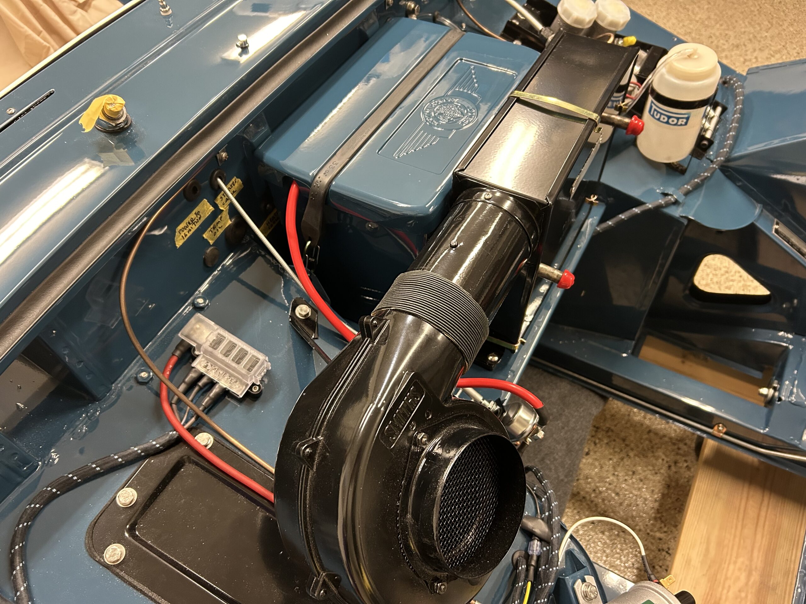
Fancy Box with Positive Cable
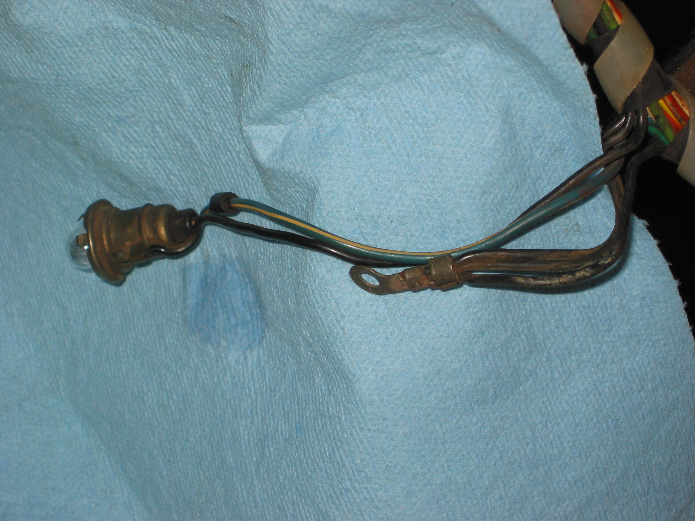
It was then time to install the rear license plate body plinth and light. This was a pretty straight forward job with little difficulty with satisfying results. These are the components involved:
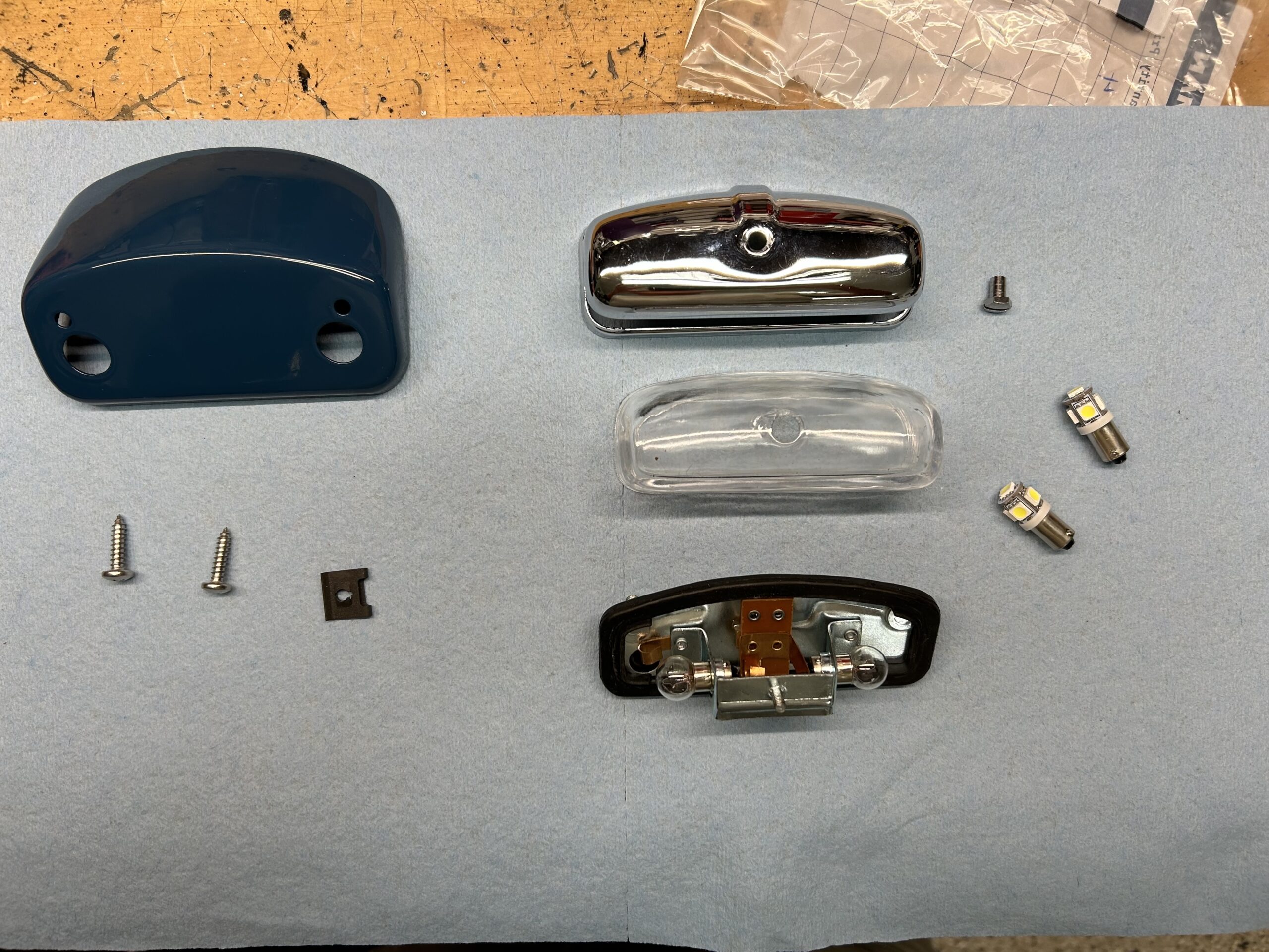
Plinth and Lamp
Partial assembly with LED lights:
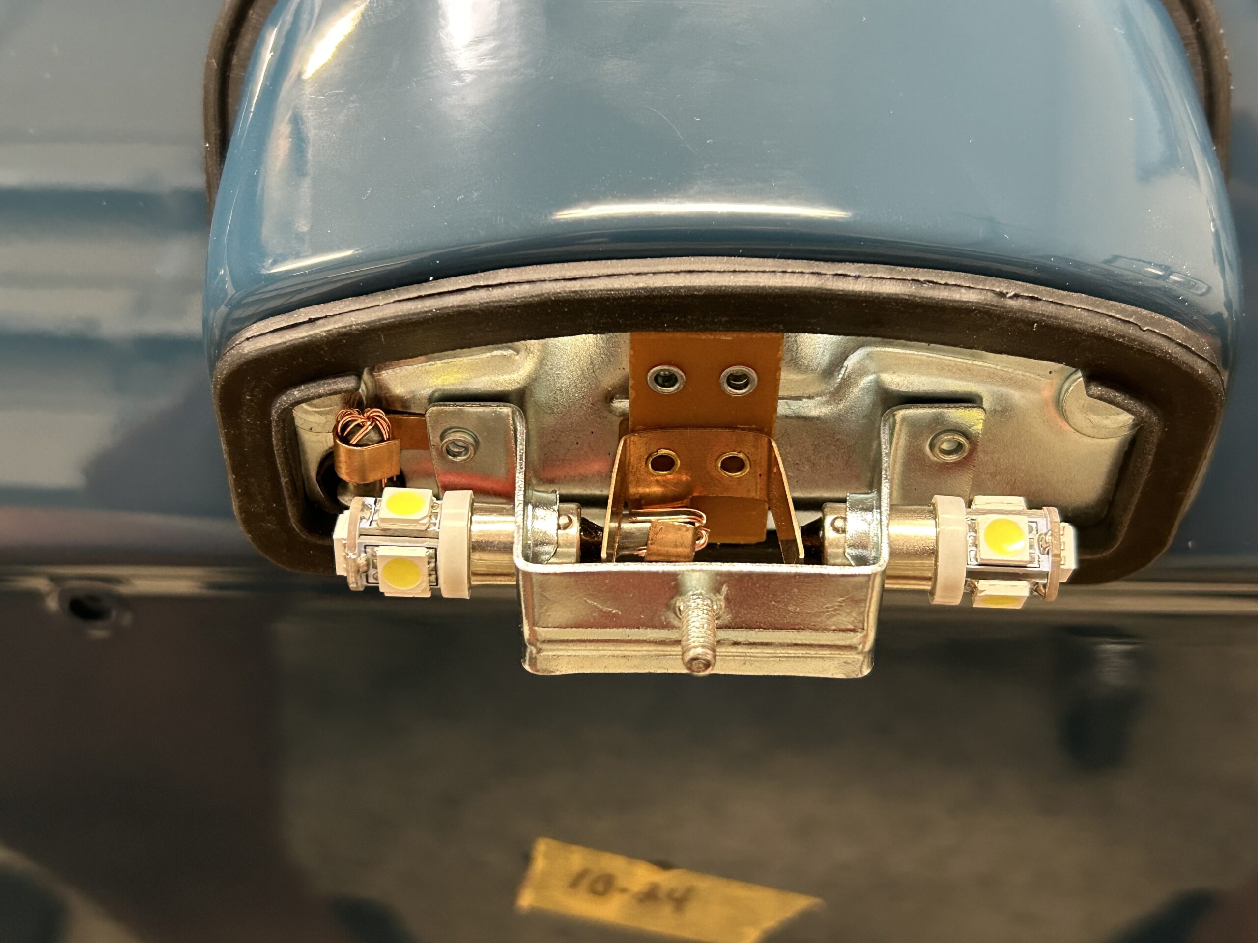
License Plate Light with LEDs
Final Installation:
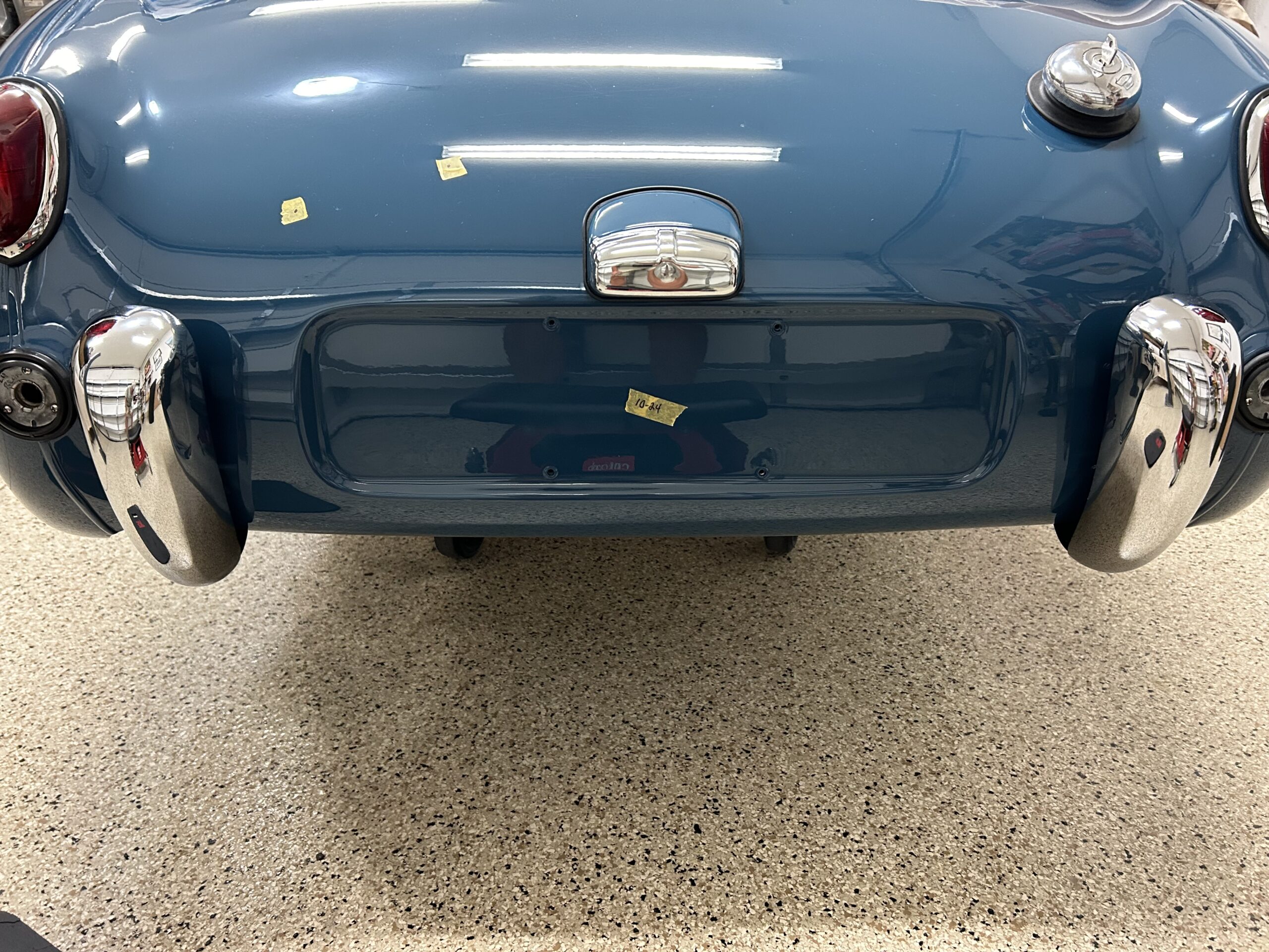
Final Installation
Bugeye Restoration Video Episode Eighty-five shows the installation process:
https://vimeo.com/1002052489/b28c484815?share=copy
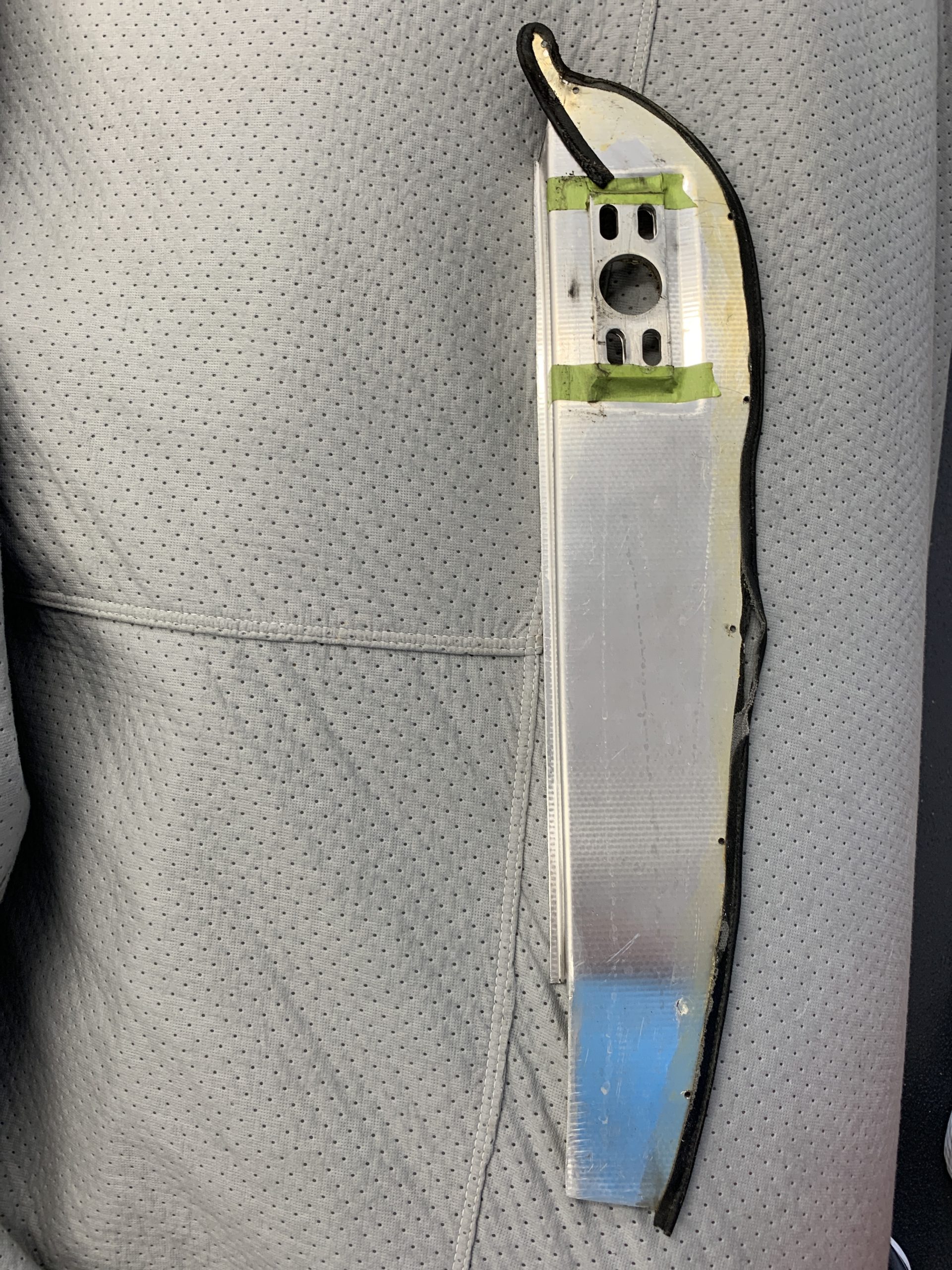
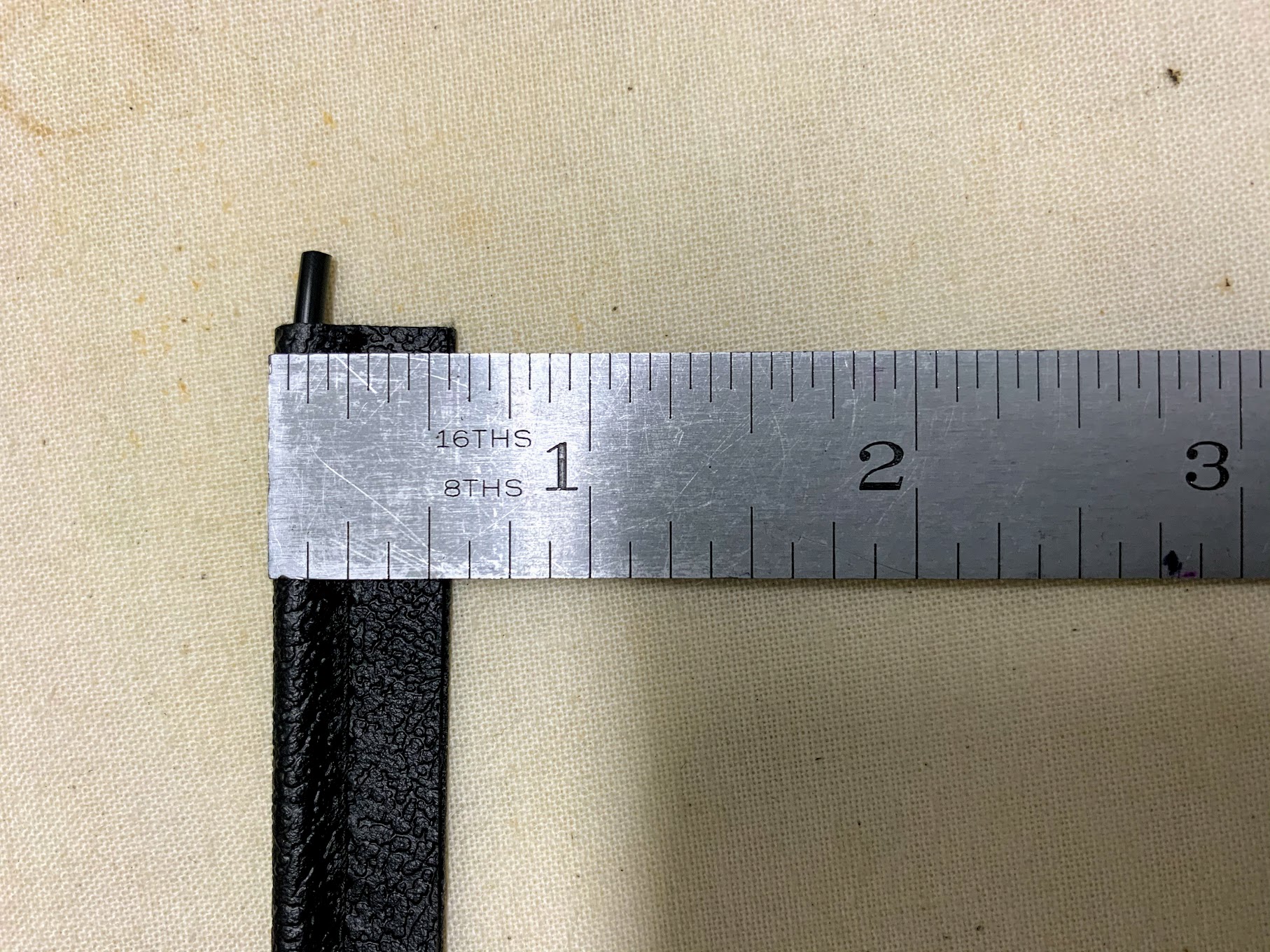
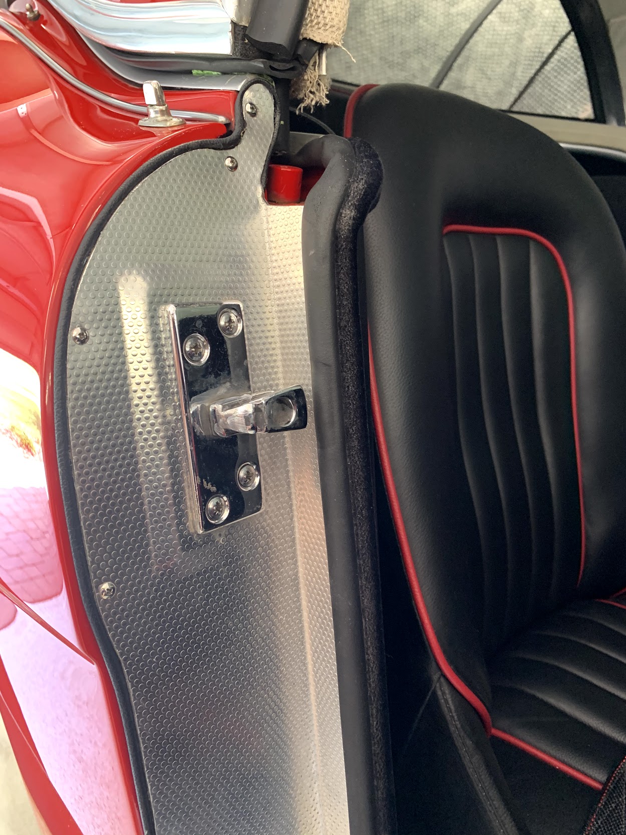
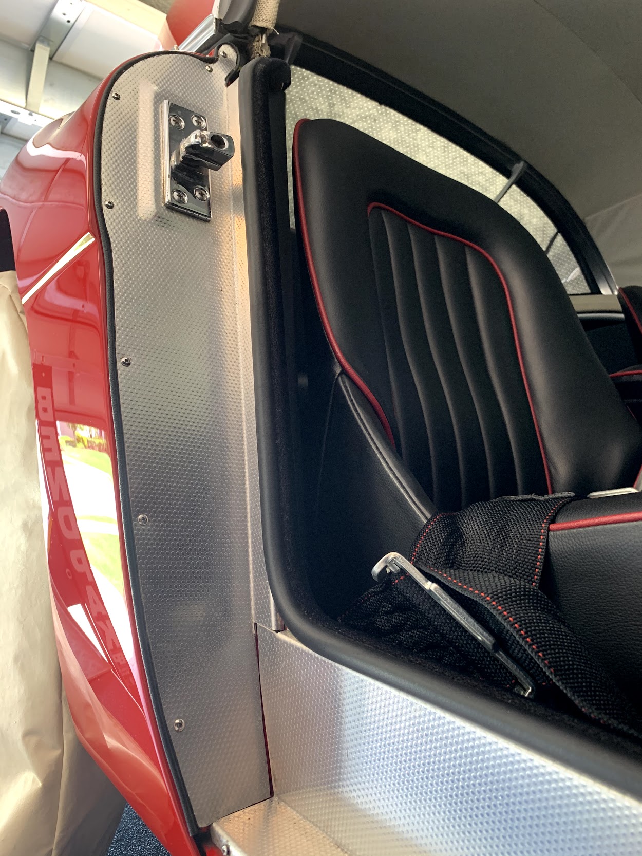
Our next project was the installation of the front cockpit aluminum trim. In our case the trimis not polished or anodized but instead is covered with vinyl matching the interior. We used contact cement to secure the trim piece to the vinyl and mounted the finished product to the body shell with nine oval head #10-32 x 3/4″ machine screws. The two outside screws will ultimately be used along with a “P” clip to secure the bristle flex trim for the doors openings.
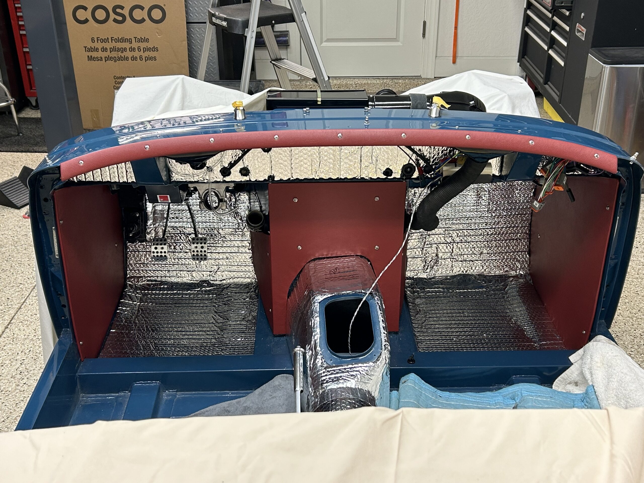
Vinyl Covered Aluminum Cockpit Trim
Sometimes adding a little chrome bling just needs to be done, so we added our chrome rear view mirror purchased from Bugeye guys. It is fastened to the body with two stainless oval head #10-32 x 1/2″ machine screws.
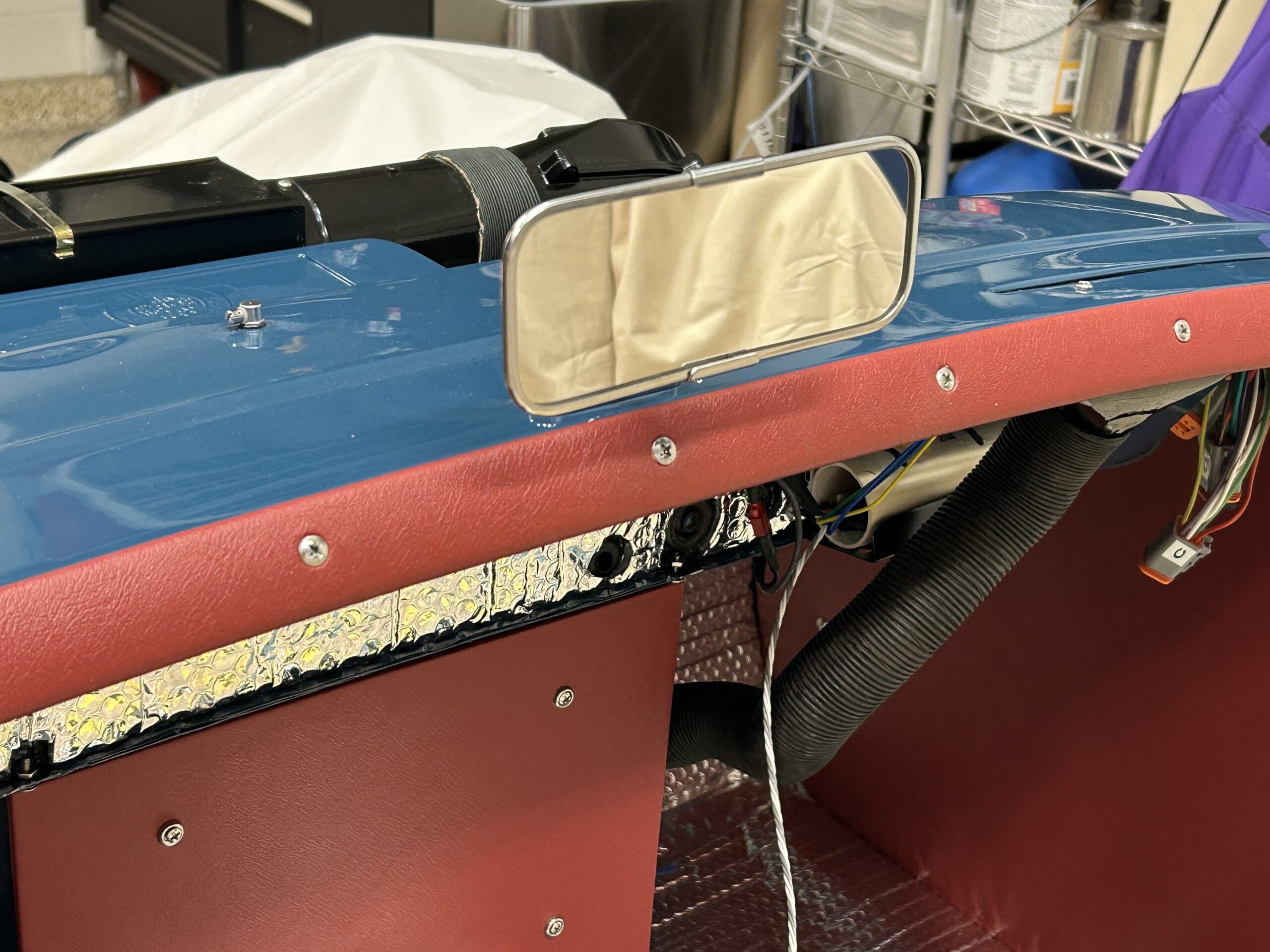
Rear View Mirror Installed
Continuing the theme of attaching more shiny parts to the car, we mounted the rear cockpit molding. We used chrome oval head #10-32 x 3/4″ and 5/8″ to fasten the strip of aluminum to the body. Unlock nuts were used to keep things tight and in place.
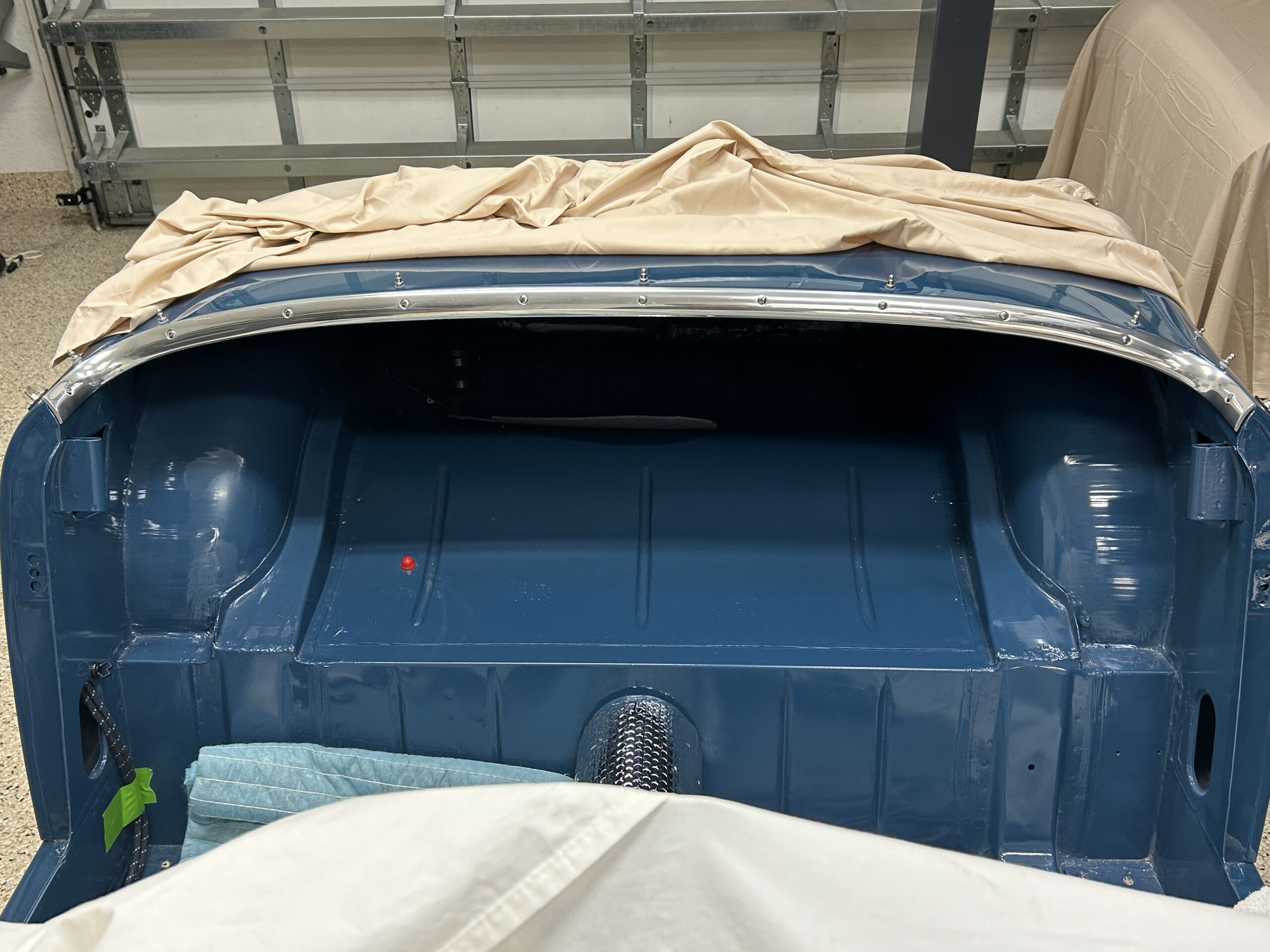
Rear cockpit molding
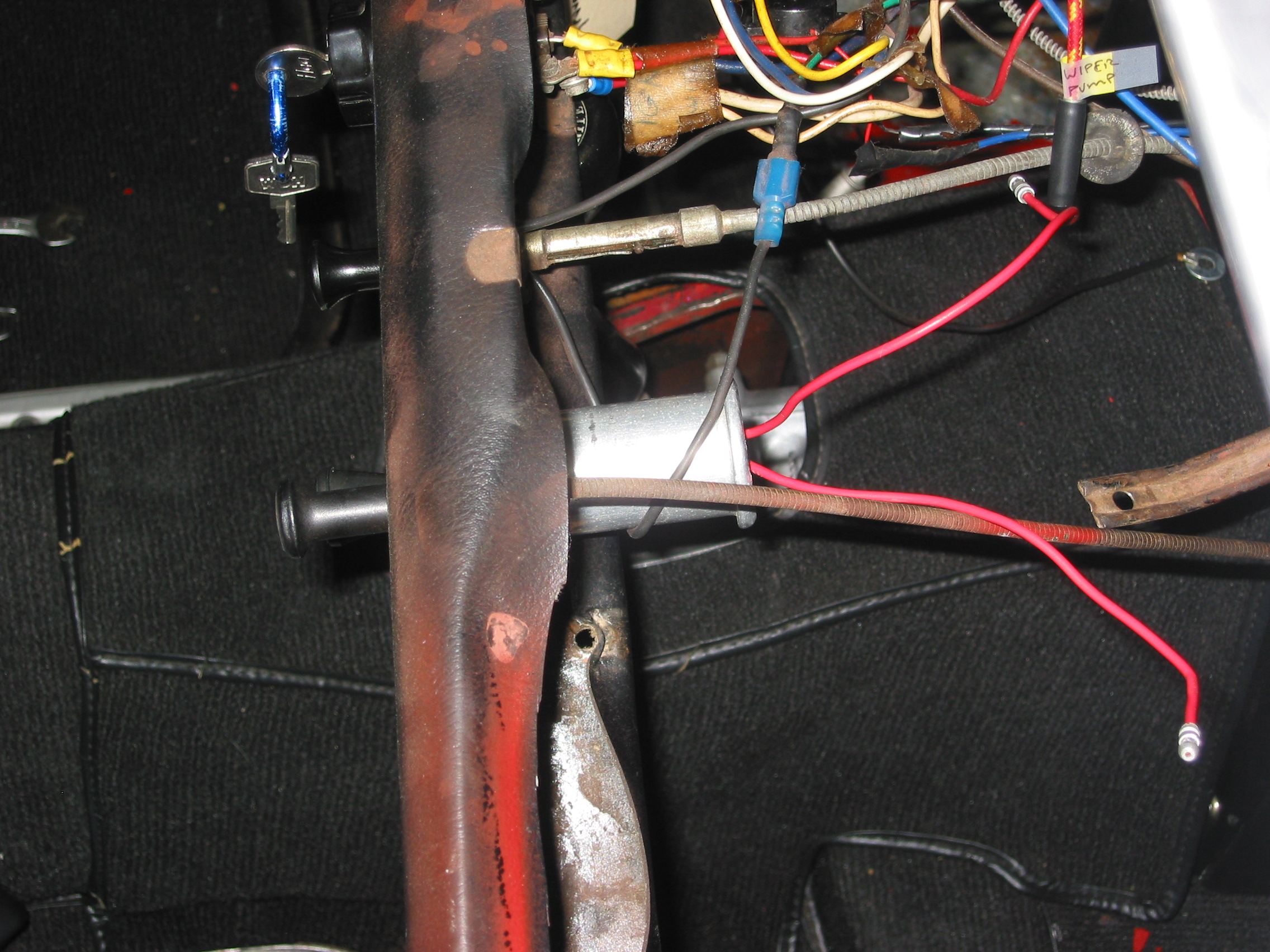
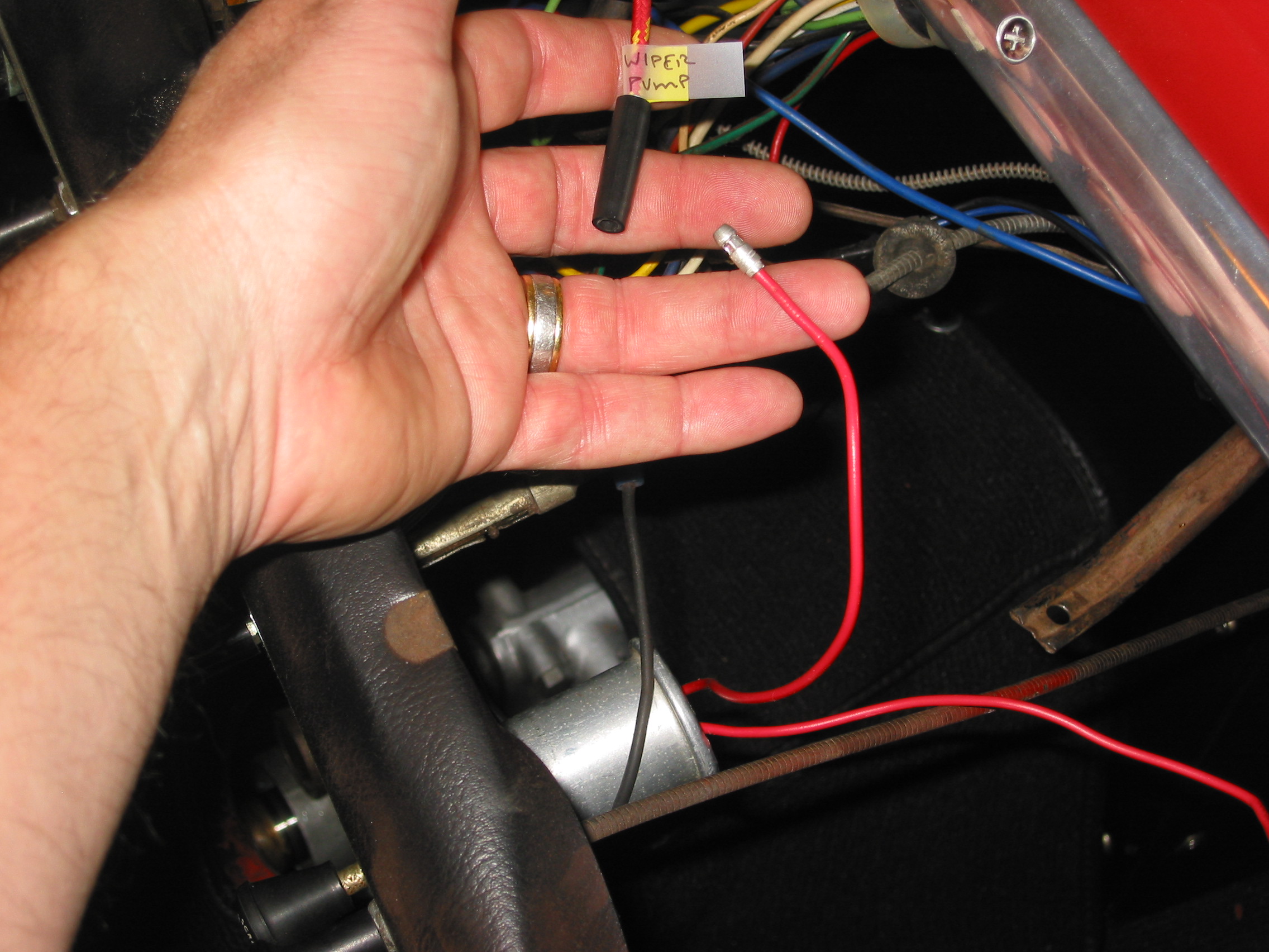
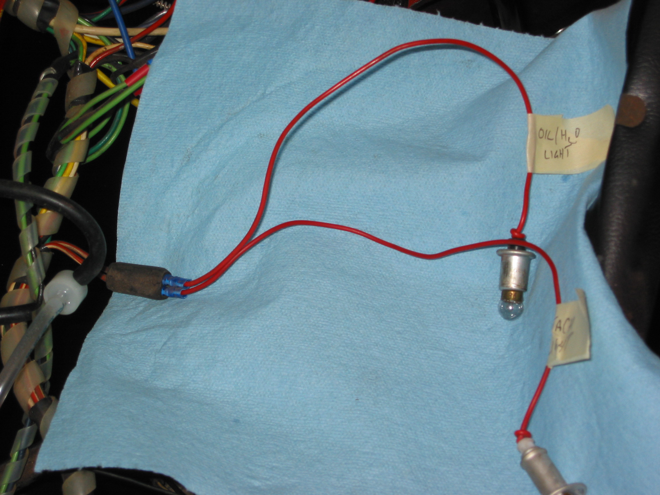
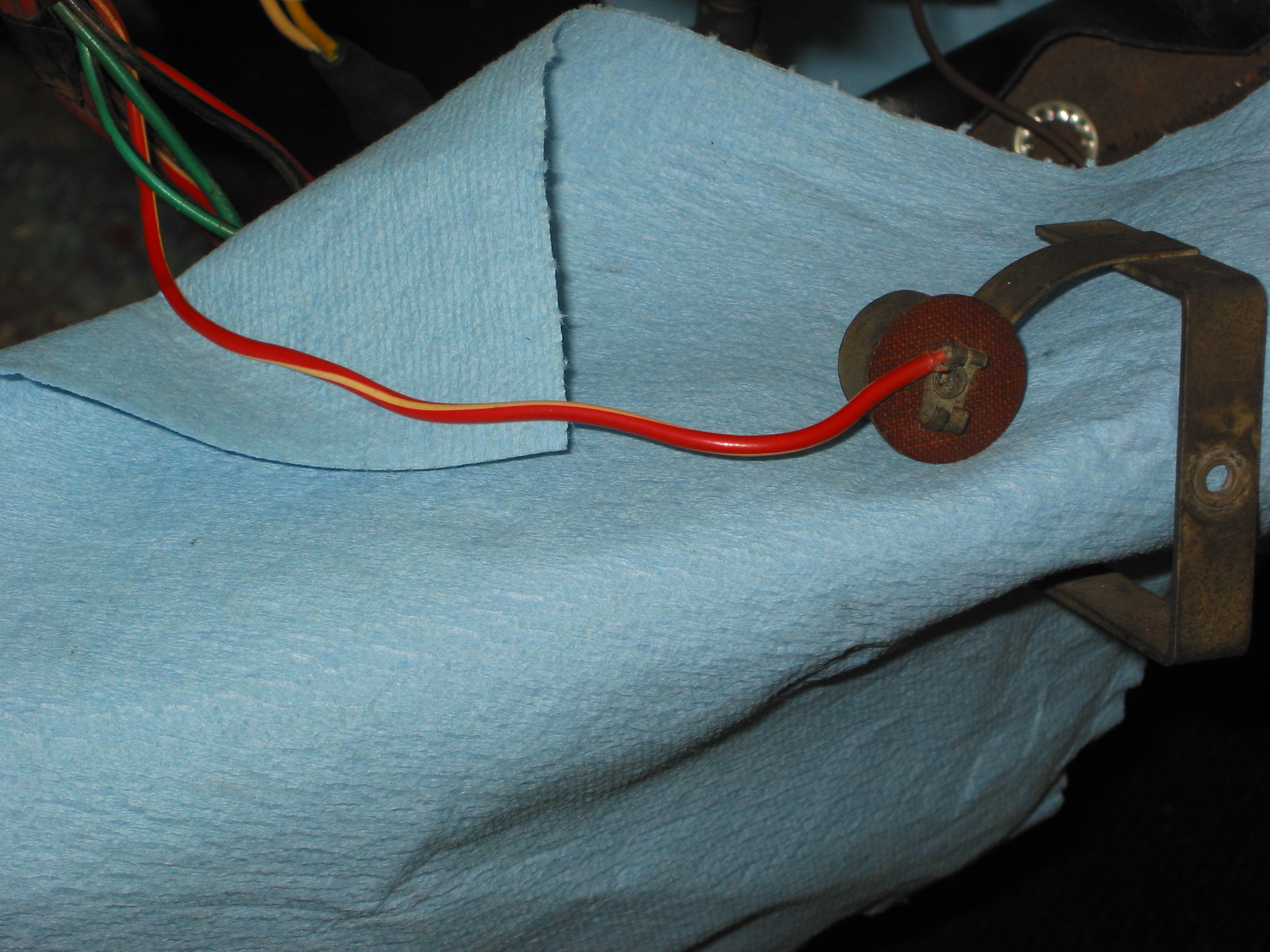
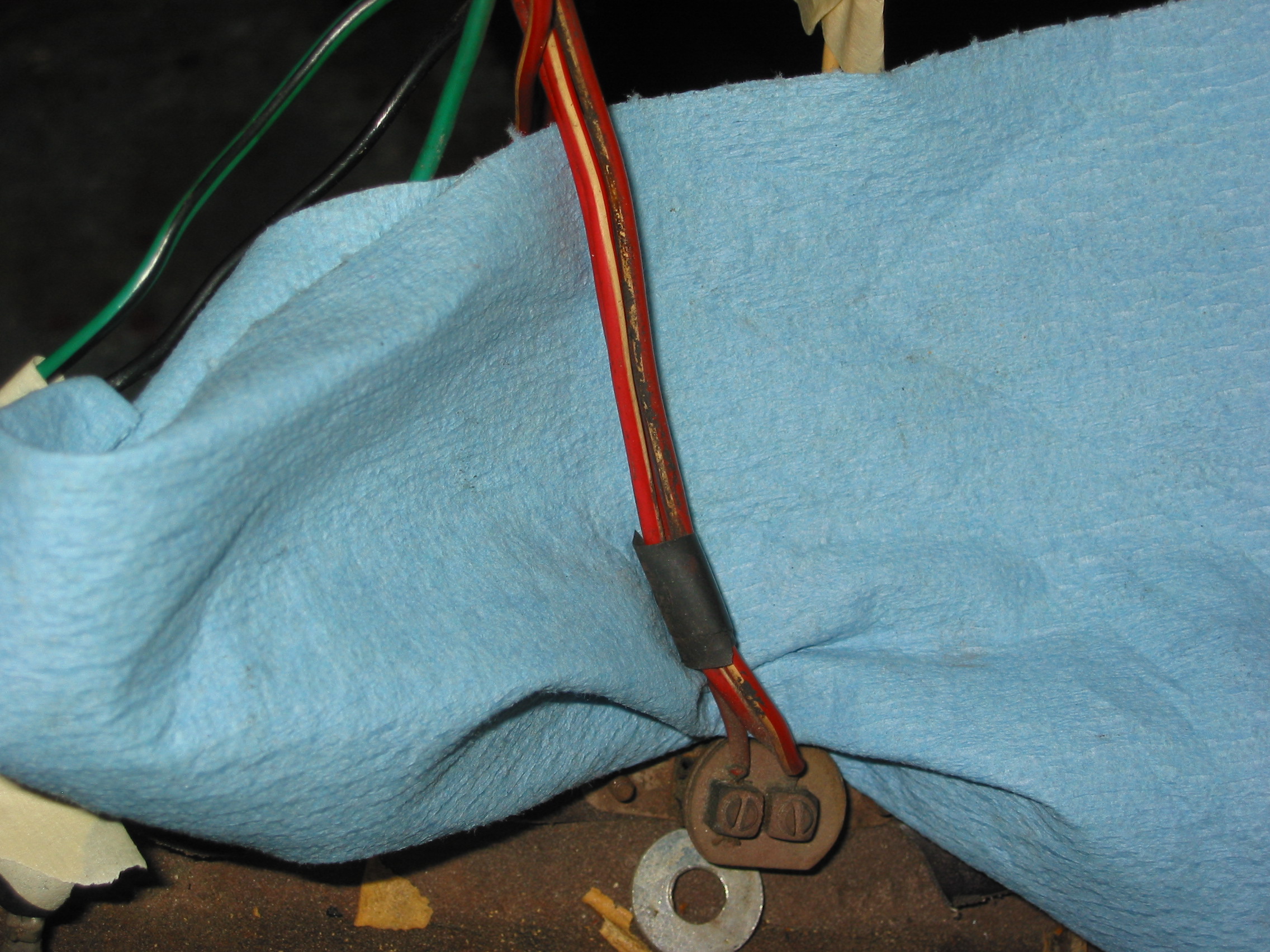
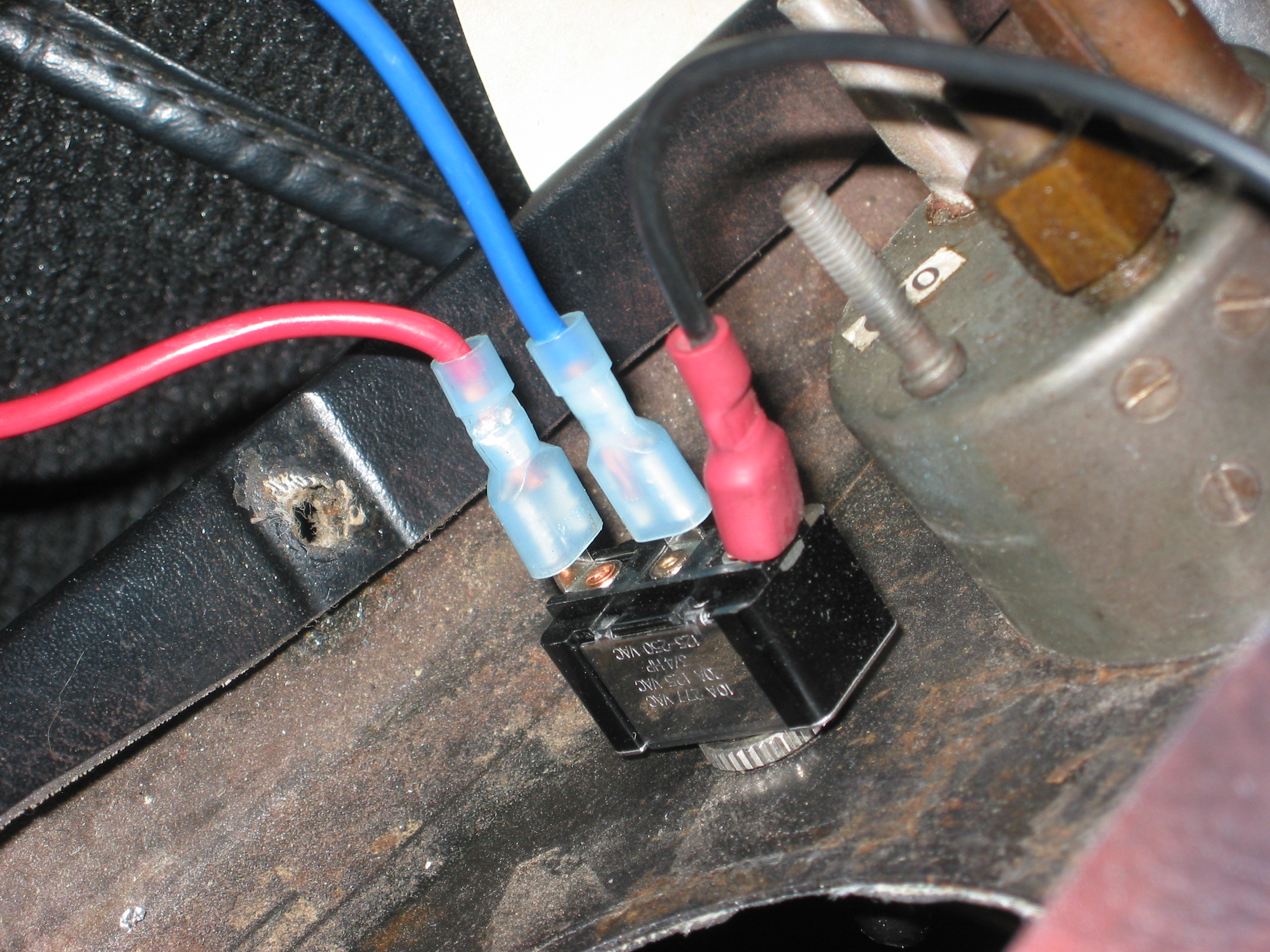
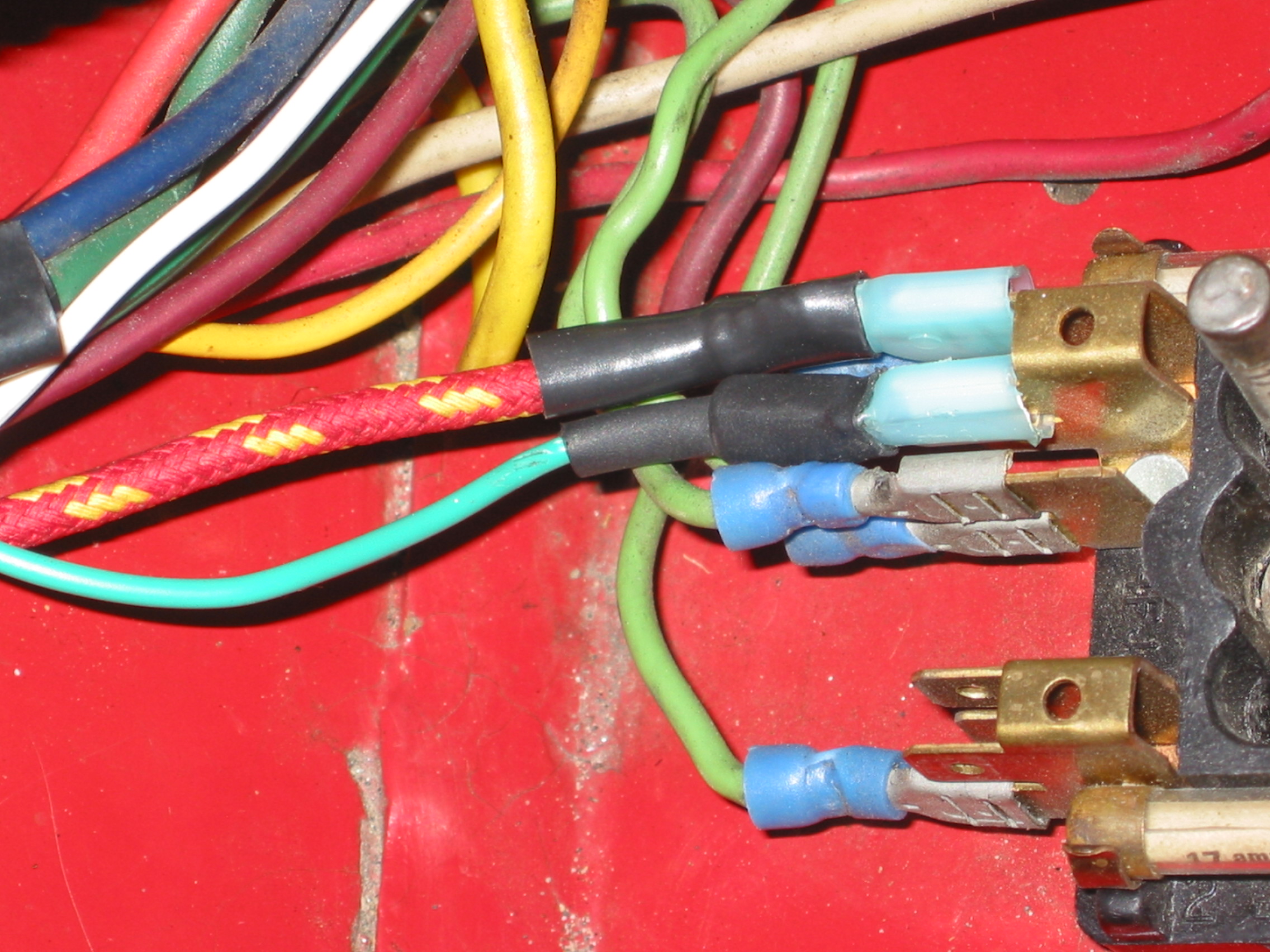
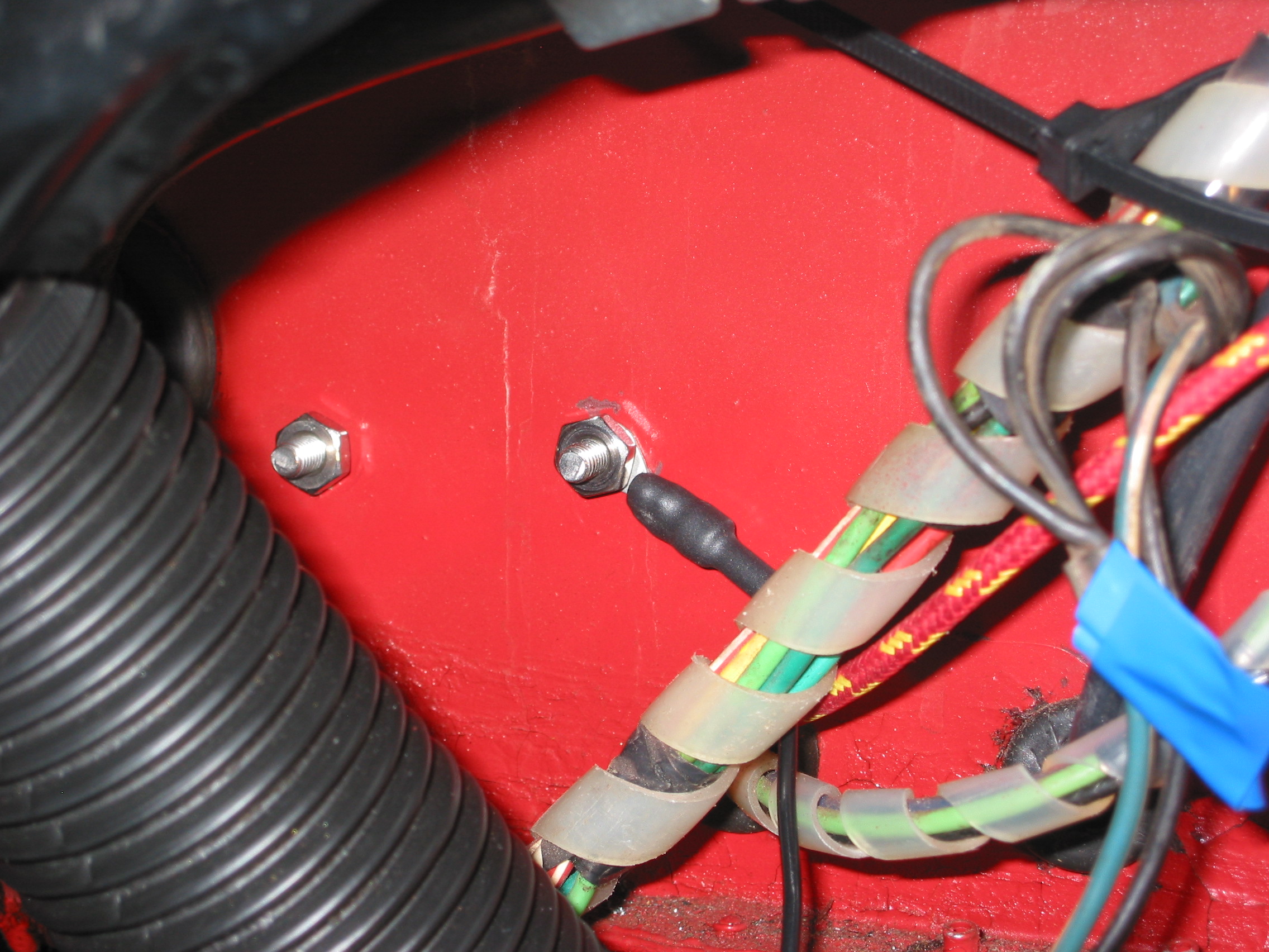
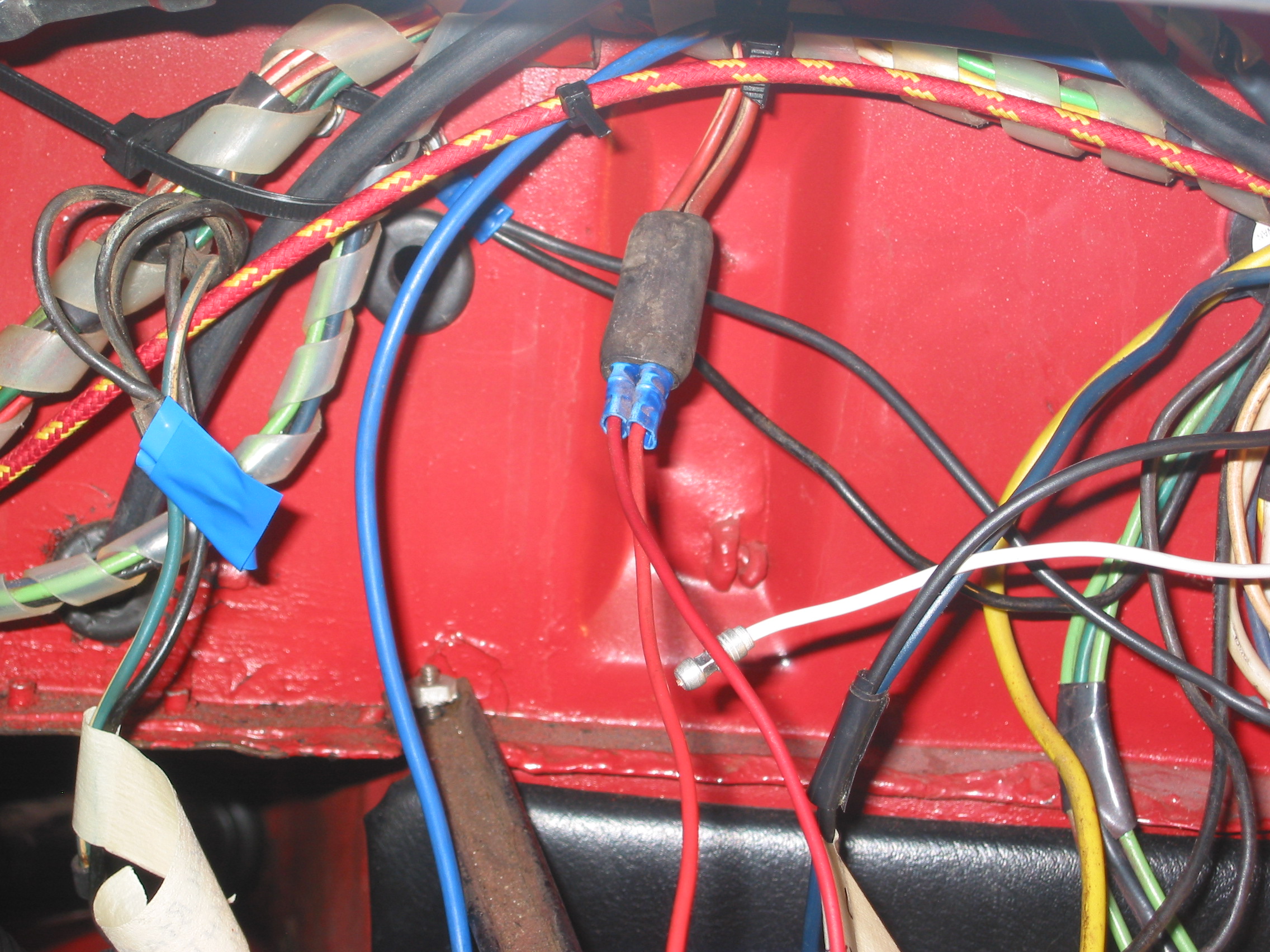
We want to use our AFR gauge to help with initial tuning after we get the car on the road so we added a temporary red wire parallel to the main harness from fuse position #19 in the Classic technologies relay/fuse box. We will pull out the wire once we have the car running the way we like!
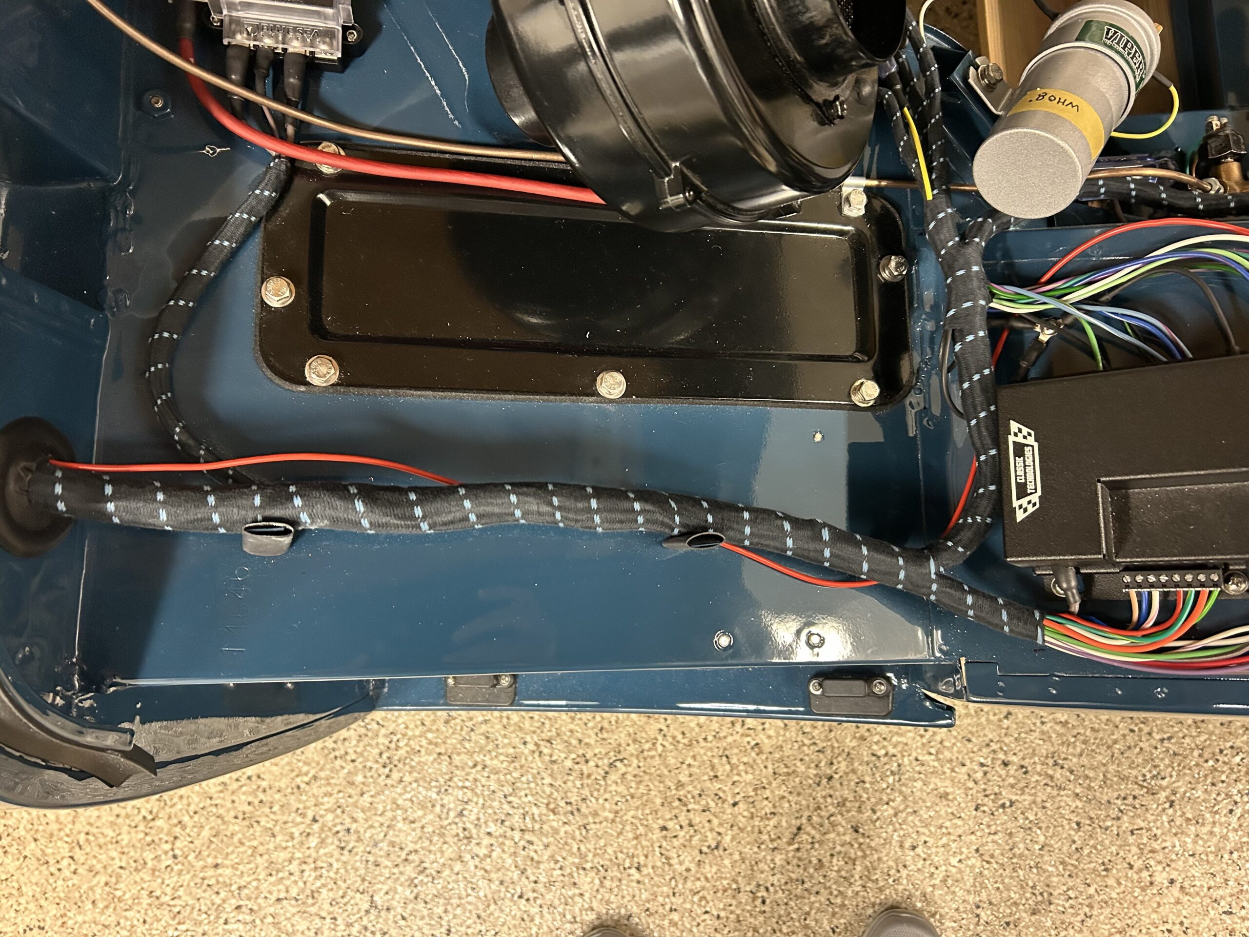
Temporary Red Wire for AFR Gauge