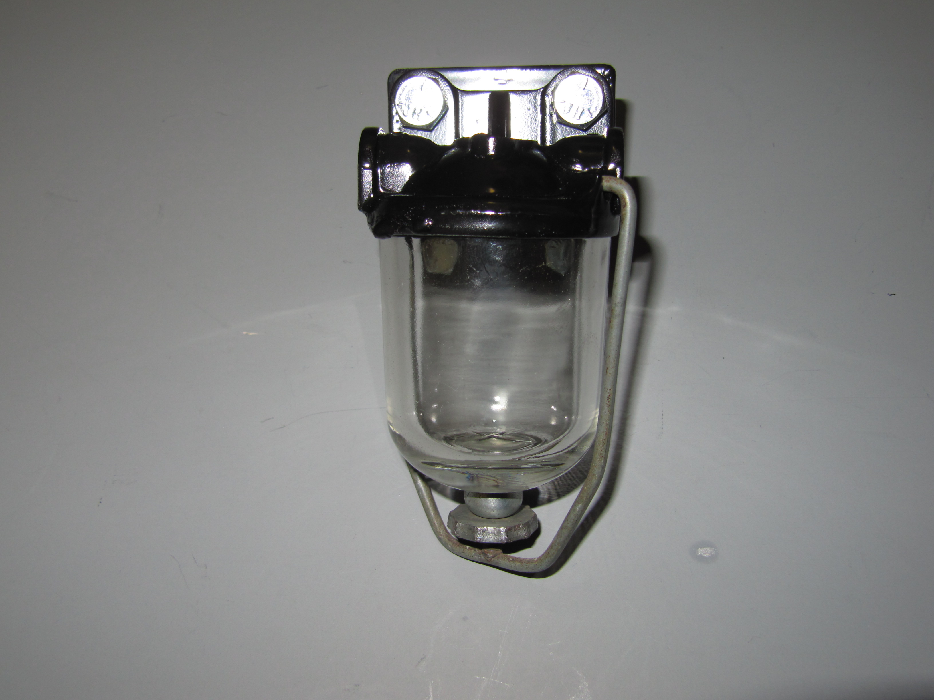
Petrol Filter
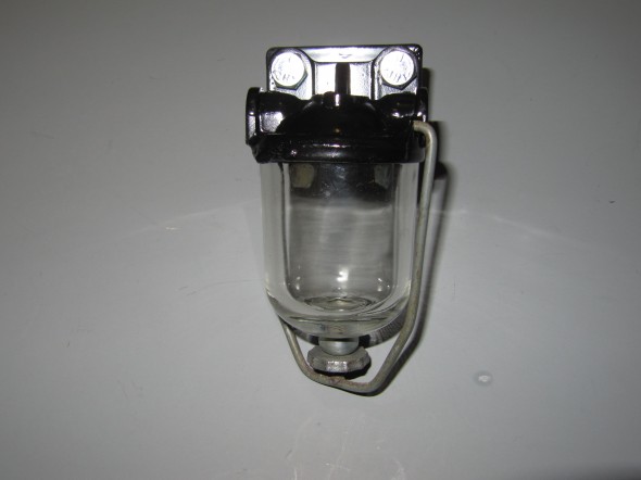
AC supplied the fuel filtration device for the Jaguar. My early version includes a filtration screen, but newer versions have a paper filter in the bowl.
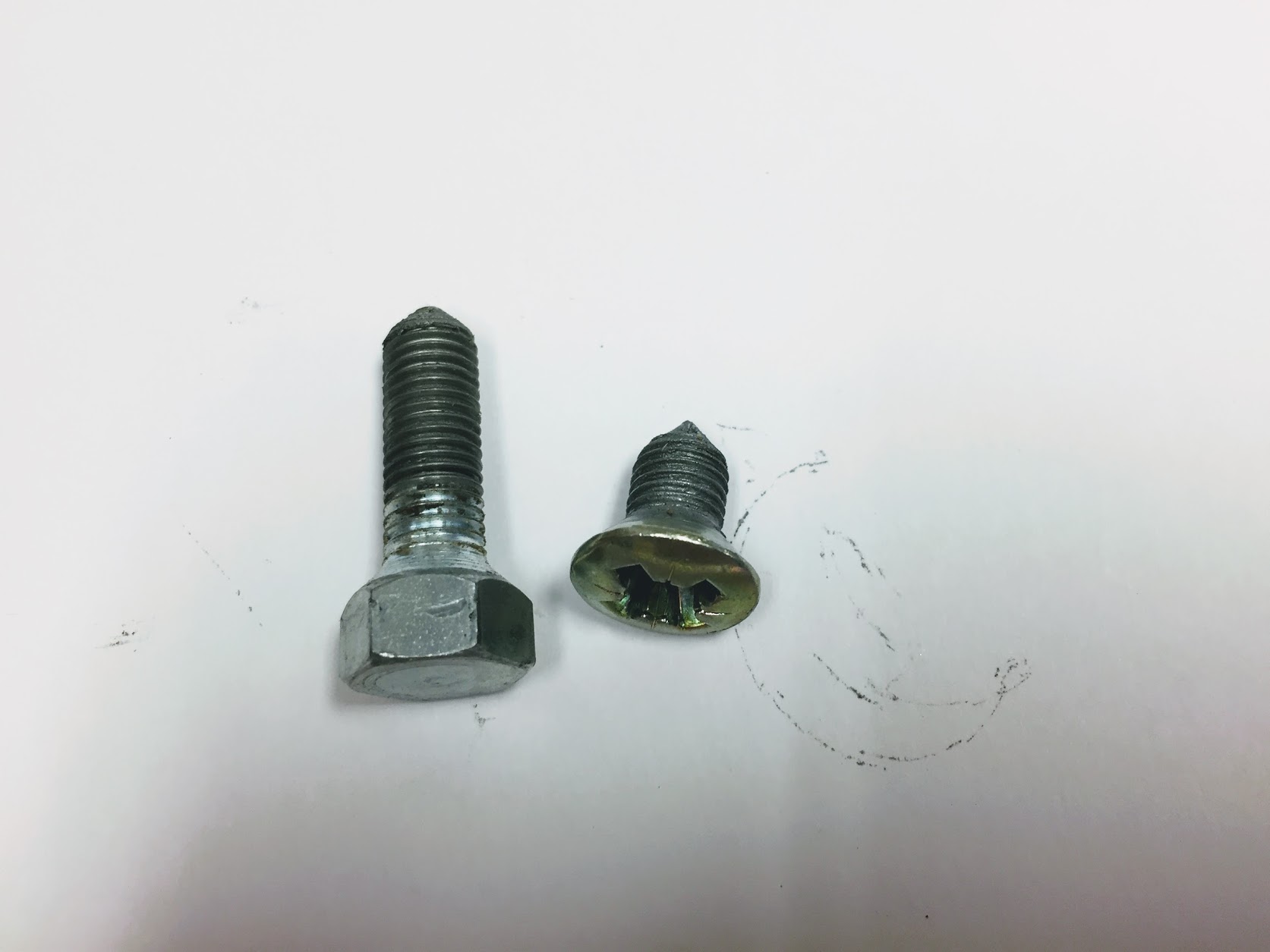
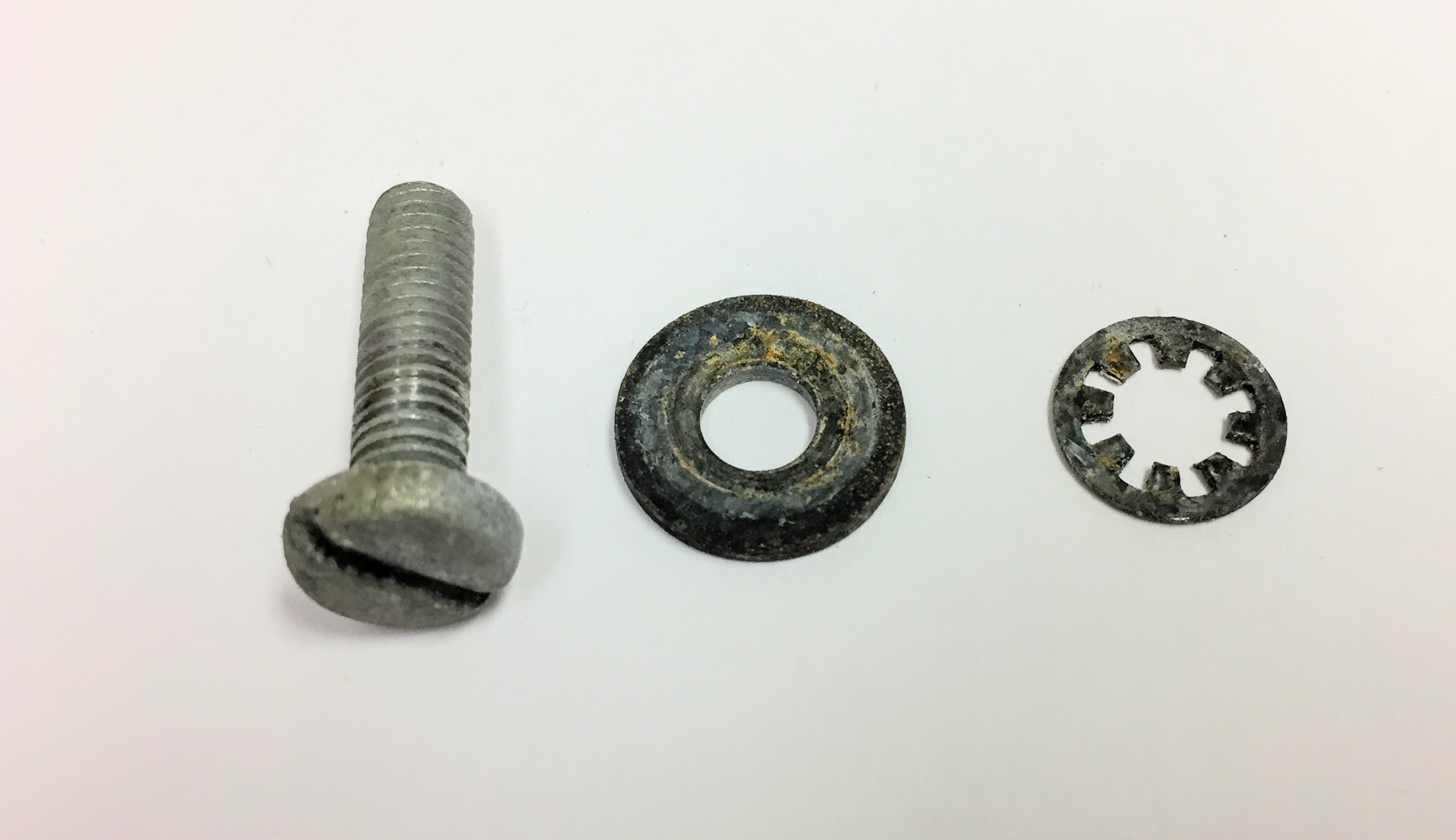
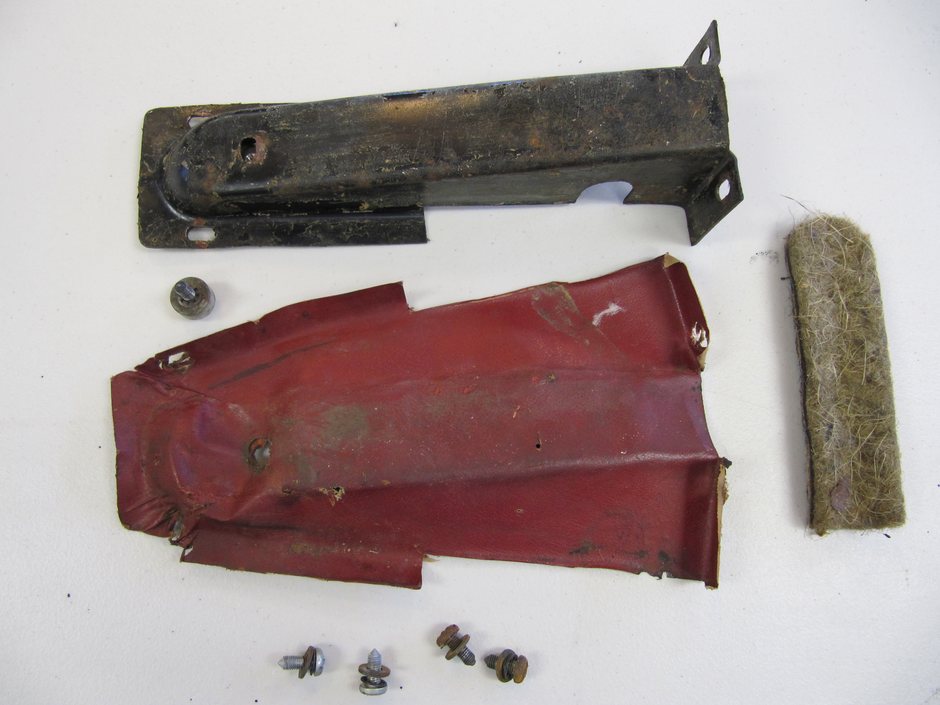
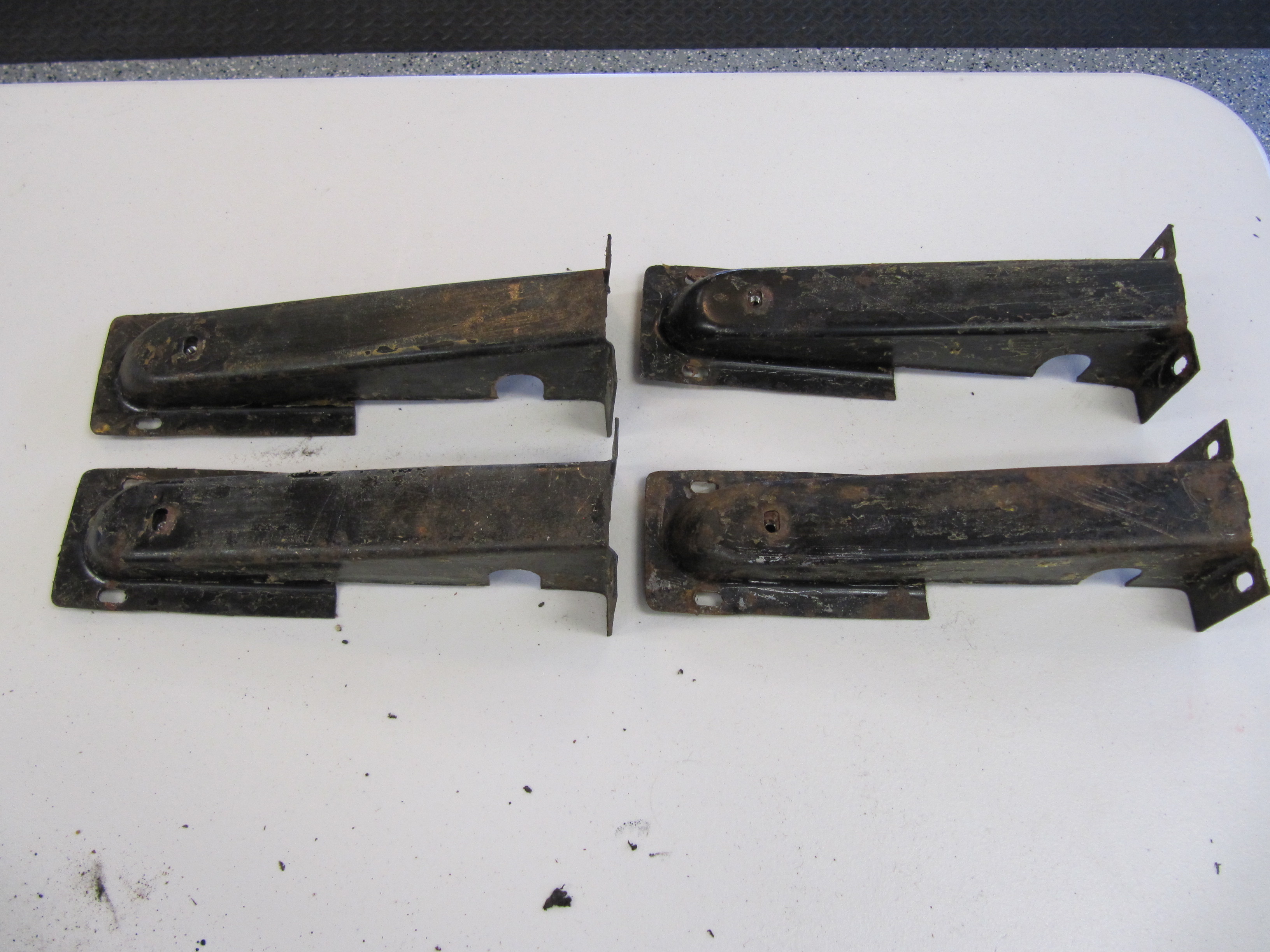
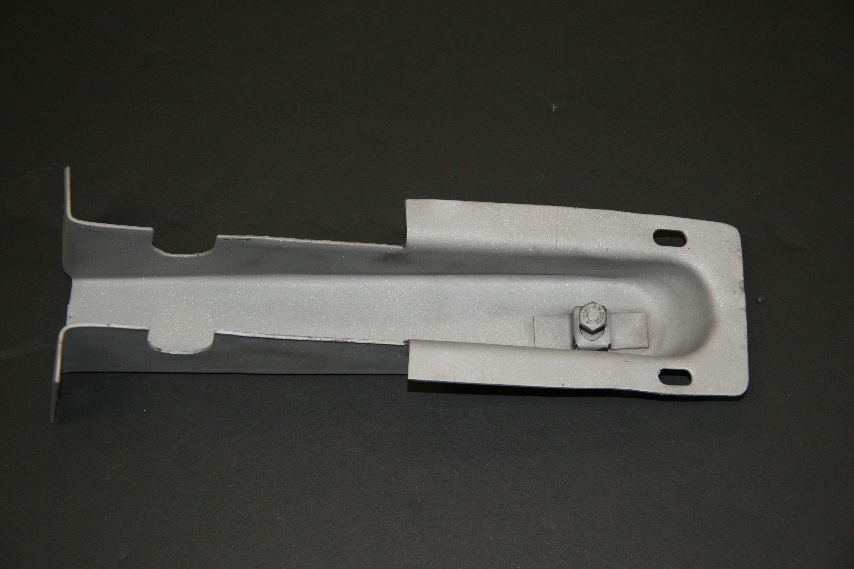
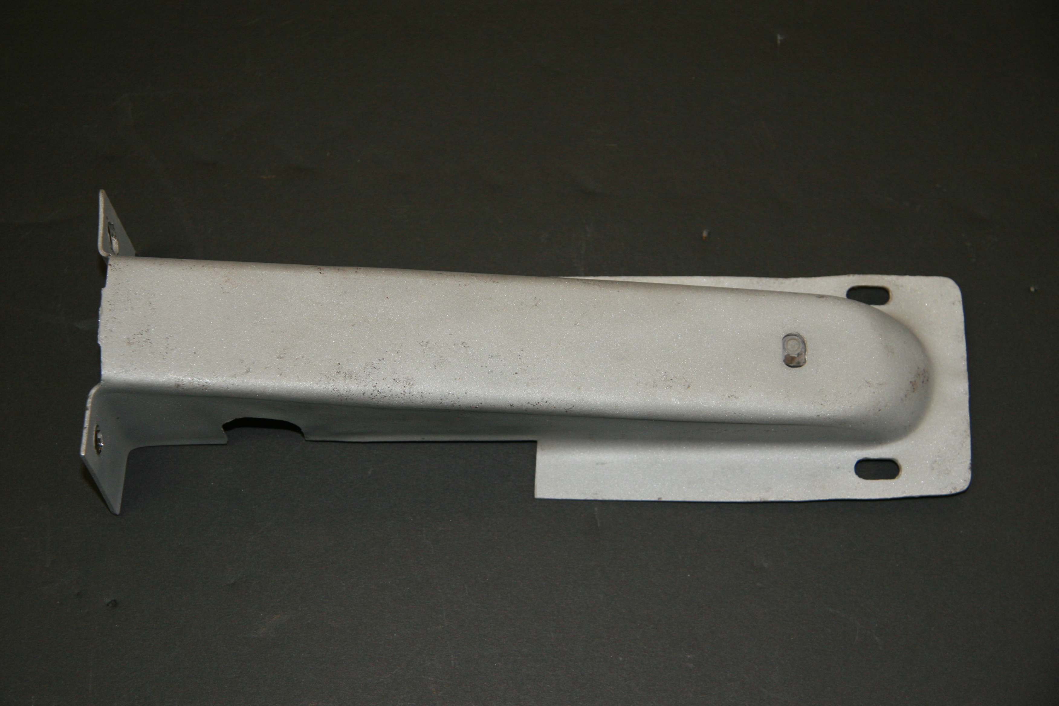
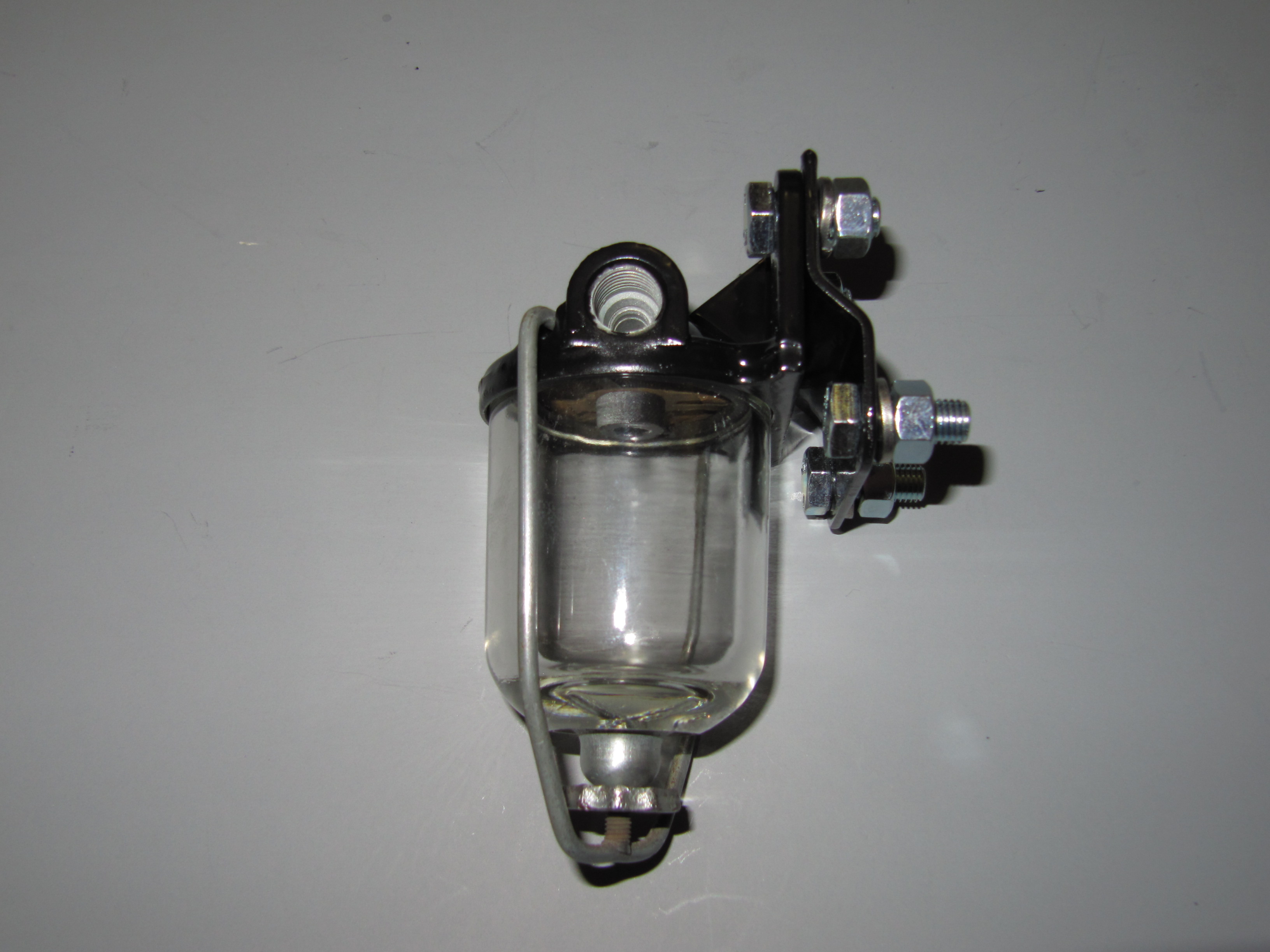
The filter is bolted to a mounting bracket with two 5/16″ – 24 x 3/4″ hex head bolts, split washers and hex nuts. The bracket and filter are then mounted to the RH wing valance with two 5/16″ – 24 x 3/4″ hex head bolts, split washers and hex nuts.
Petrol Filter
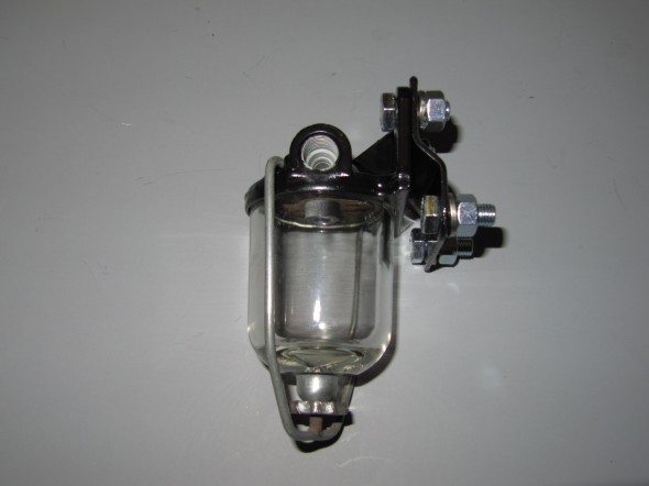
Petrol Filter & Bracket
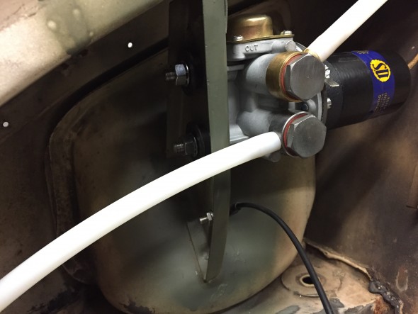
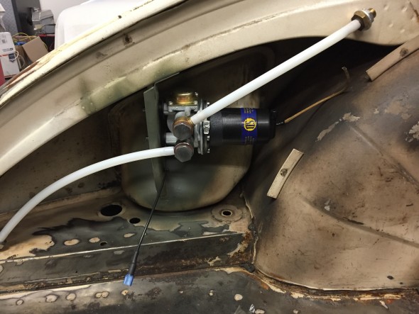
I trial fit the fuel filter and fuel pipe to the RH valance.
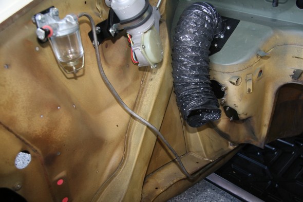
Fuel Filter and Fuel Pipe Installed
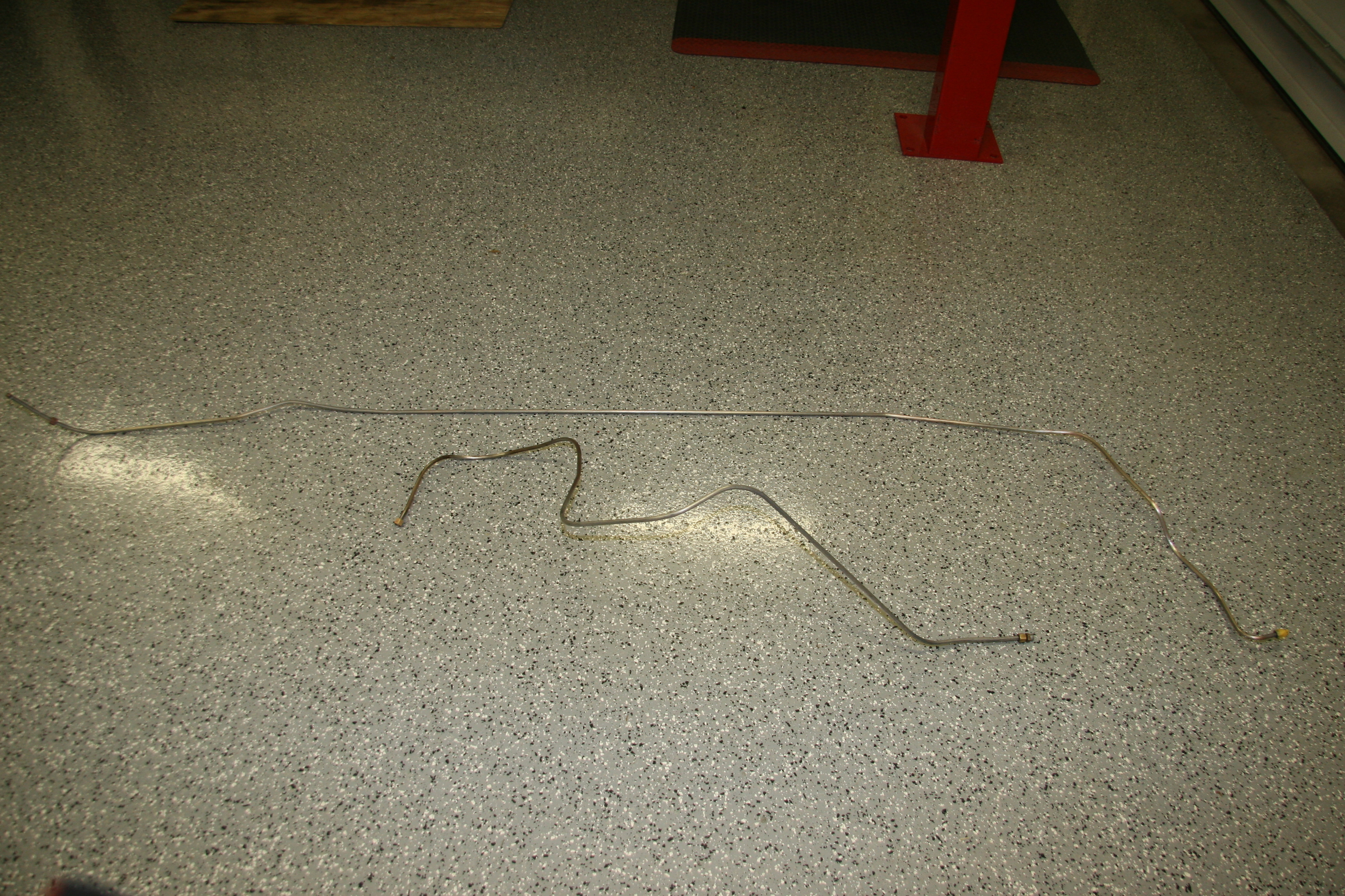
Fuel Lines
I am replacing the hard brake lines, but the original hard fuel lines were in very good shape. I just cleaned them before reinstalling.
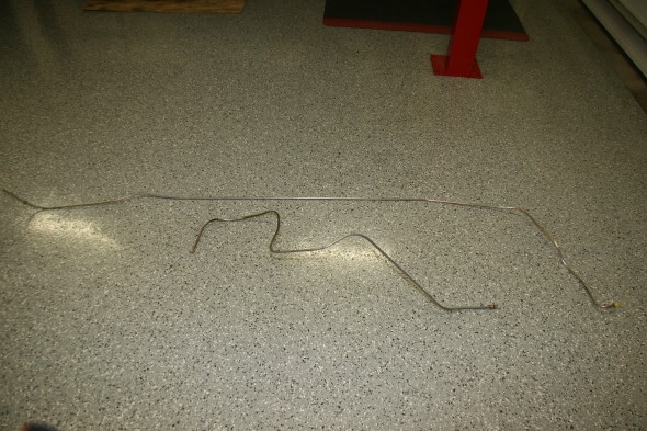
The hard fuel lines run along the RH frame rail. Rather than using the original mounting clips, I used a double stainless steel clip that permitted running the fuel and brake pipe in parallel on one side of the clip and the battery cable in the other. Information and photos of the fuel line installation can be found here” https://valvechatter.com/?p=6627.
Petrol Tank Filter
I ordered a new filter for the tank.
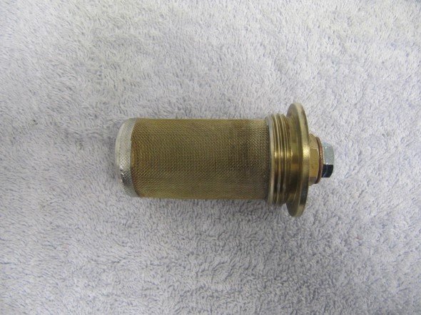
Petrol Tank Filter
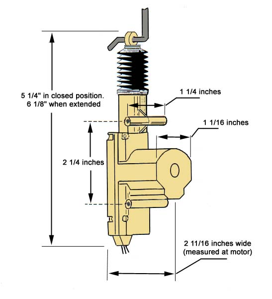
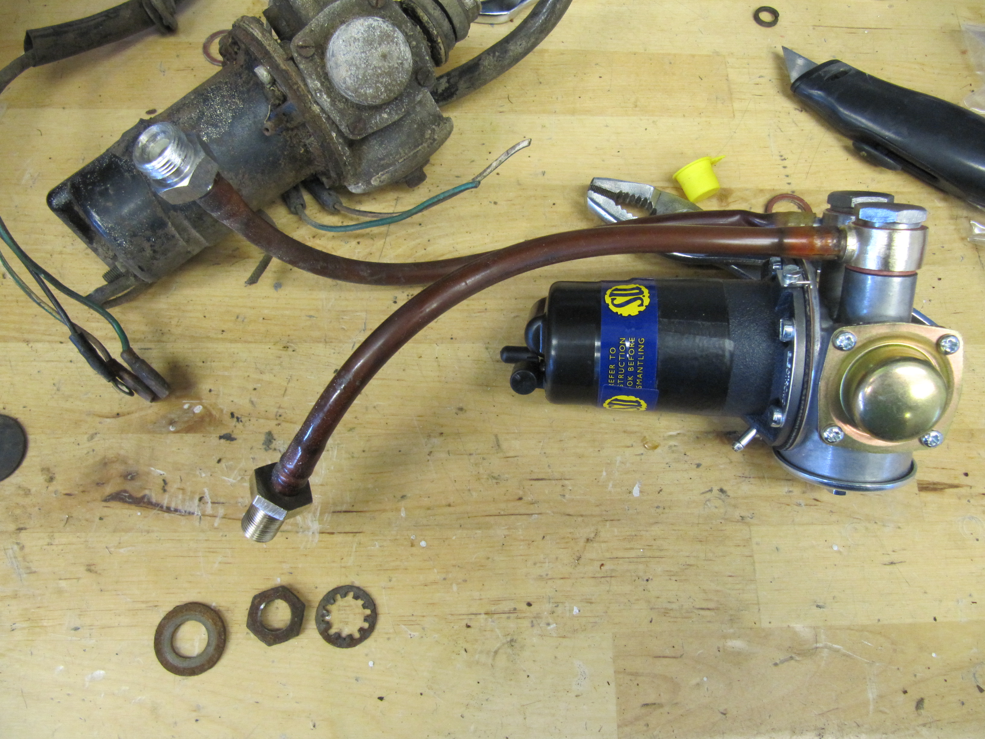
Petrol Pump
I ordered a new SU electronic petrol pump to replace the old, but still functioning unit.

SU Electronic Petrol Pump AZX1308EN
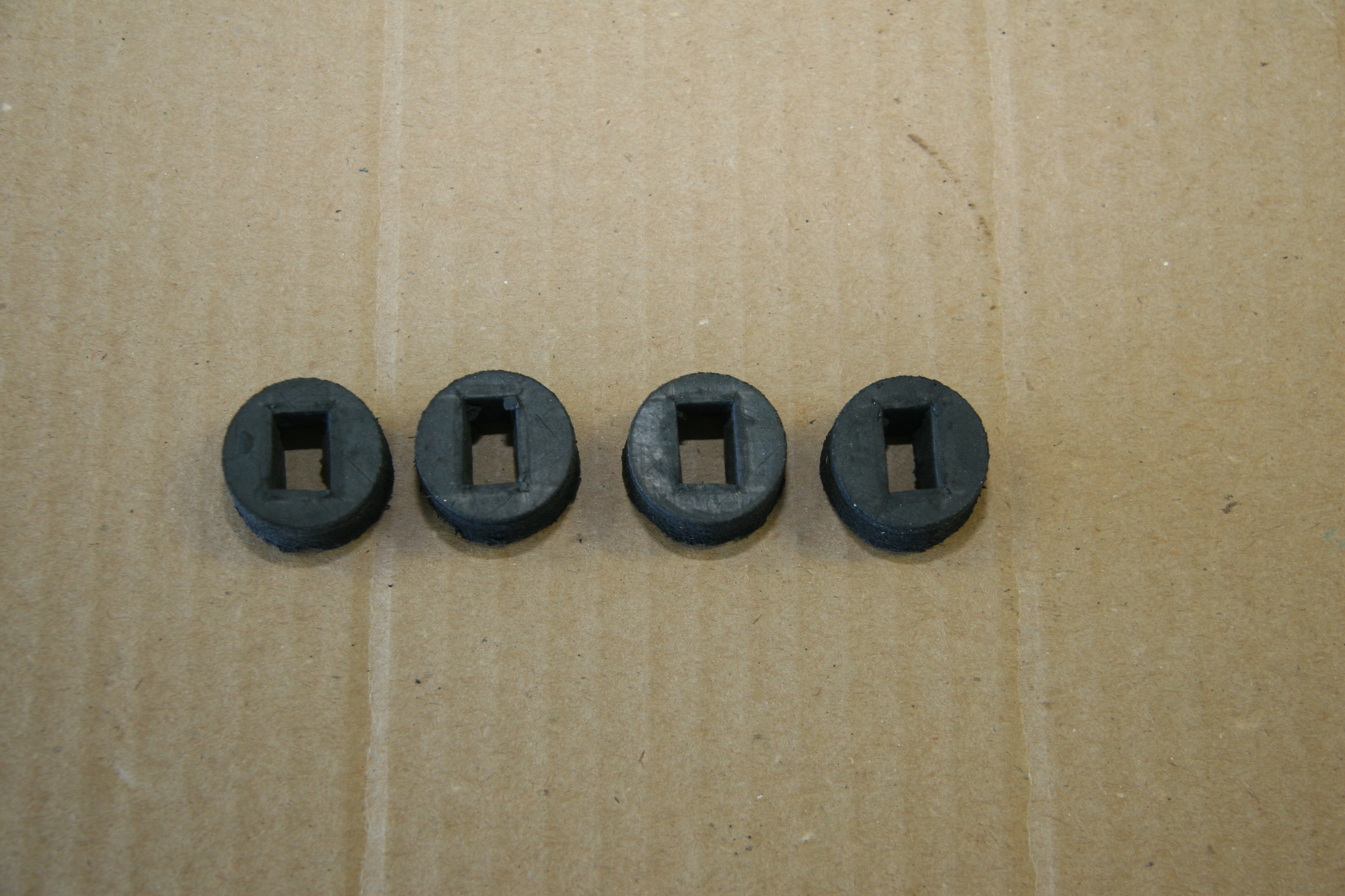
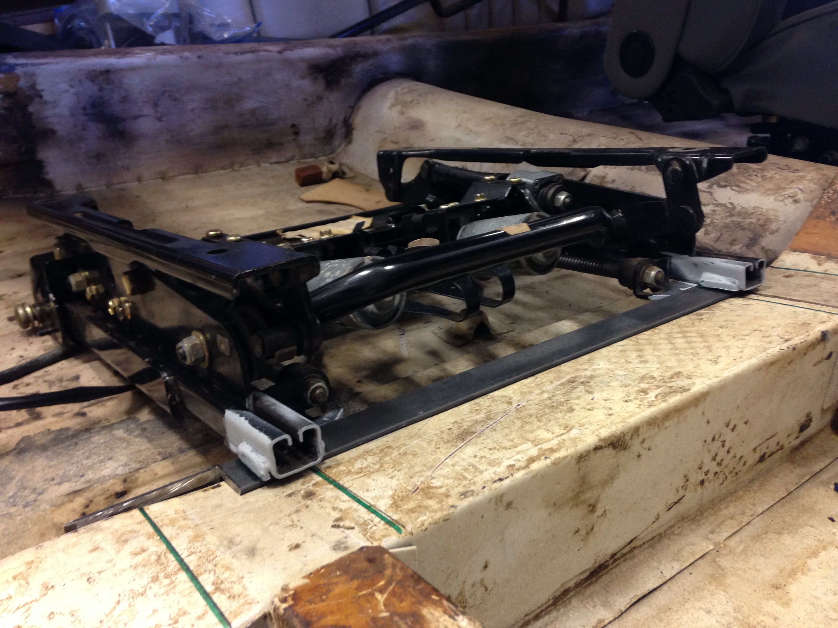
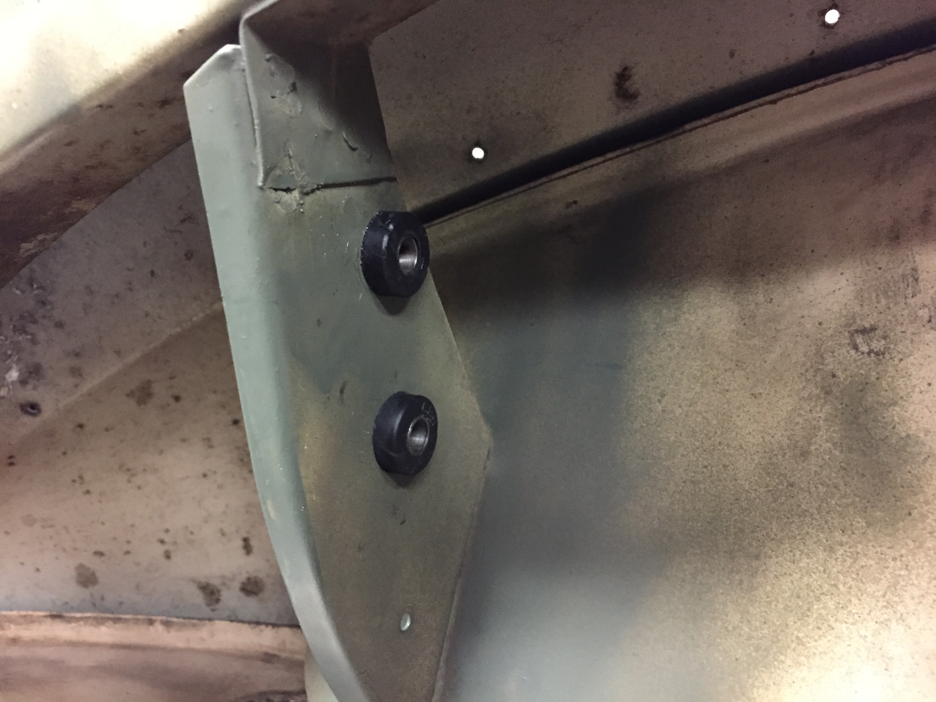
As part of the trial fitting process, I installed the two rubber grommets with their metal “distance tubes” in the boot. Pushing the grommets into place is no easy task. I placed them in boiling water for a few minutes to soften them and it did seem to help. Also put a little vaseline on the mounting plate to which they are affixed.
Petrol Filter & Bracket
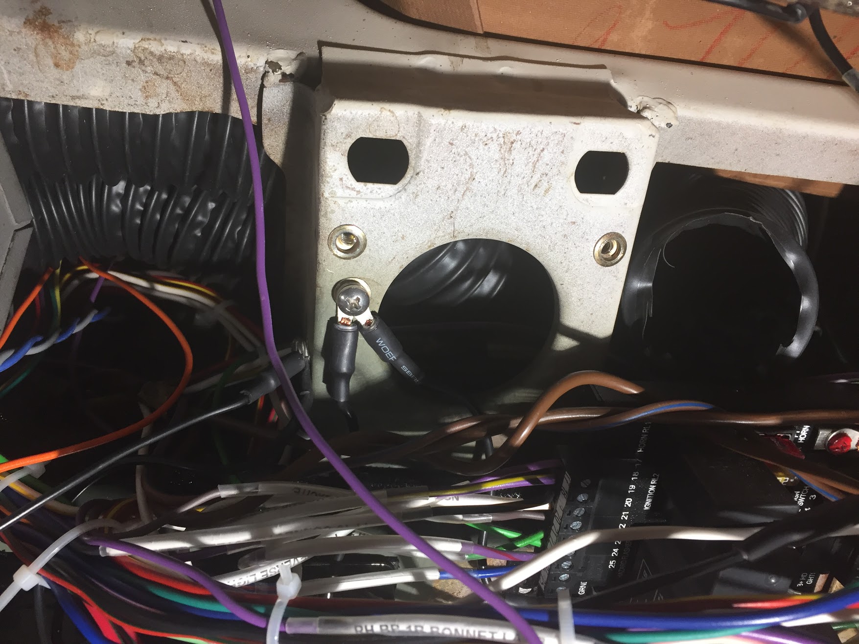
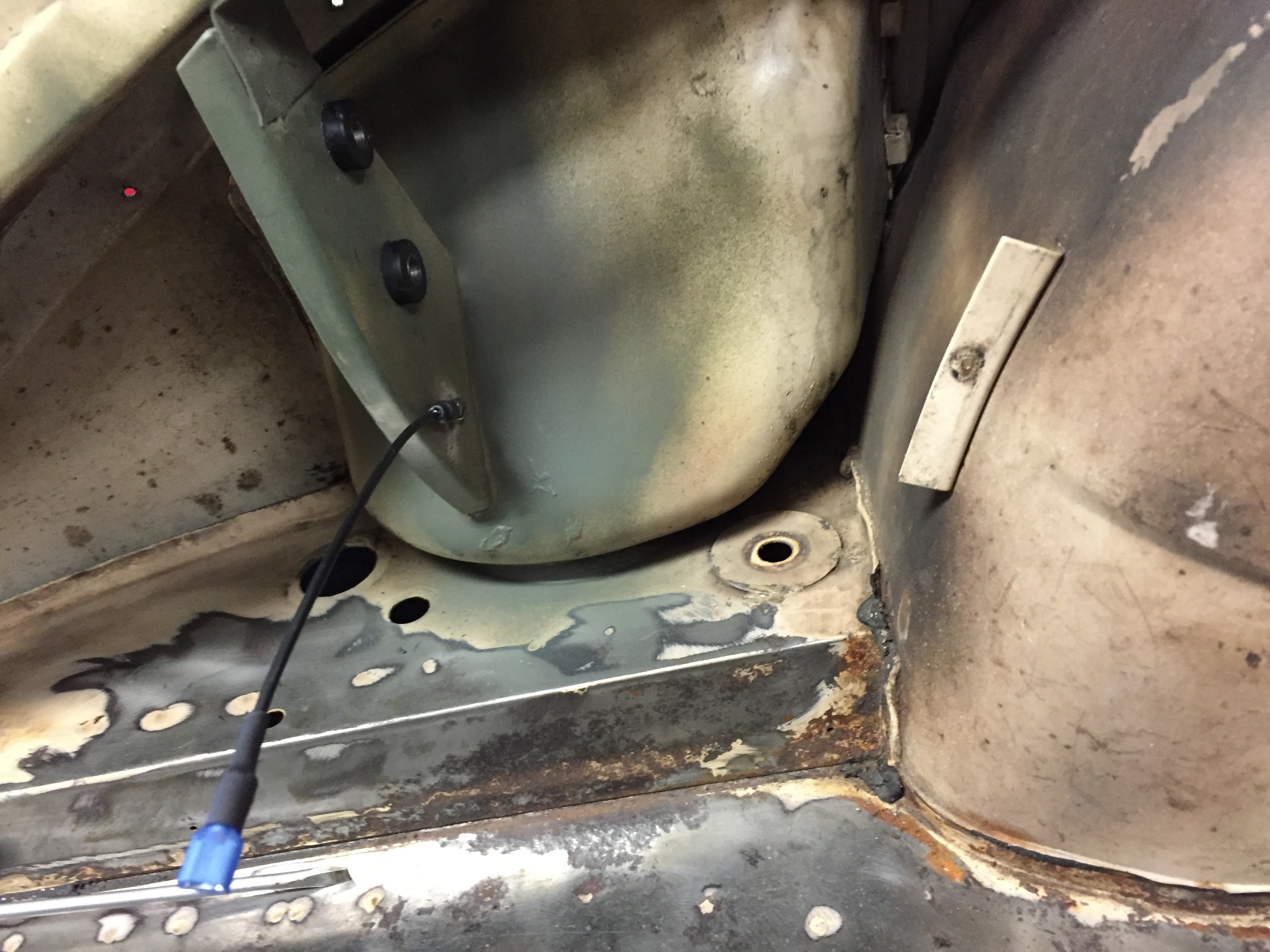
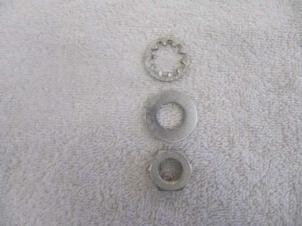
A black 14 AWG wire is used as the ground for the pump and it attaches to the mounting plate via a #10 – 32 x 1/2″ machine screw, flat washer, split washer, and nut. A spade connector is located on the pump for the other end of the wire.
Ground Wire Mounting for Fuel Pump
I cut the new nylon hoses, sourced from SNG Barratt, to length using the originals as patterns, and pressed them onto their pump fittings. I then installed the pump by inserting the pump mounting studs through special large washers (to evenly compress the rubber grommets) and then fastened in place with lock washers and nuts.
Fuel Pump Mounting Studs, Special Washers and nuts
Installed Fuel Pump with Nylon Hoses
Petrol Hoses
New petrol hoses were purchased for installation. I had purchased the hard nylon tubing from SNG Barrett as shown in the image above, but have since decided to use rubber fuel hose. The rubber hose is easier to work with. I did not want to use the fuel tank for the fuel source for a test start-up of the engine, so I plumbed the fuel pump, including the relocated fuel filter, and will use a five gallon plastic fuel can sitting in the spare tire well.
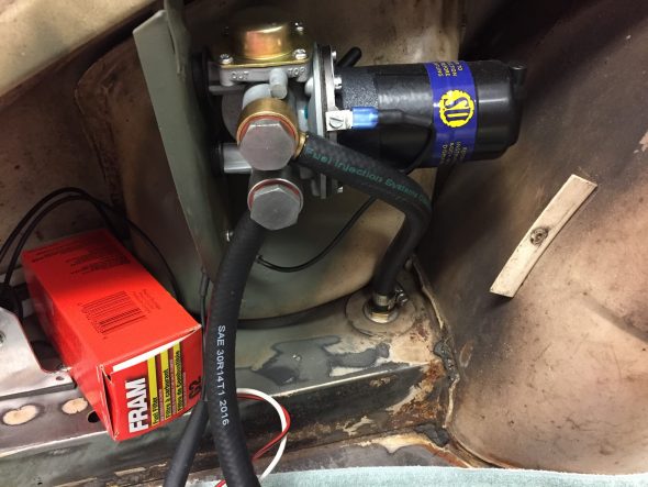
Fuel Pump Hose Fittings 5/16″ Rubber Fuel Hose
Fuel Hose with Filter to Temporary Fuel Source
The petrol hose fittings from the petrol pump were cleaned and clear cad plated for re-use.
Fasteners for Petrol Pump Hose
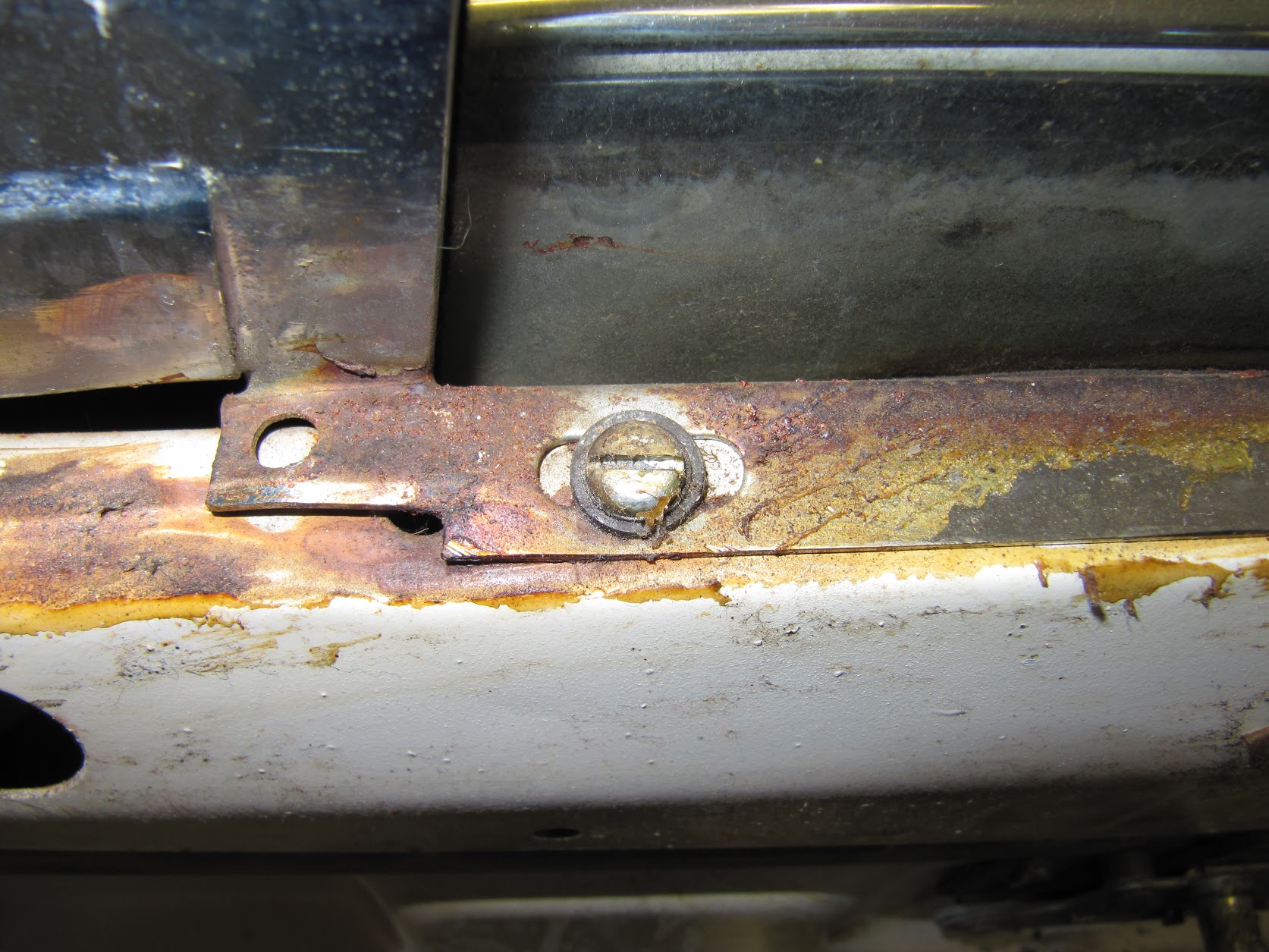
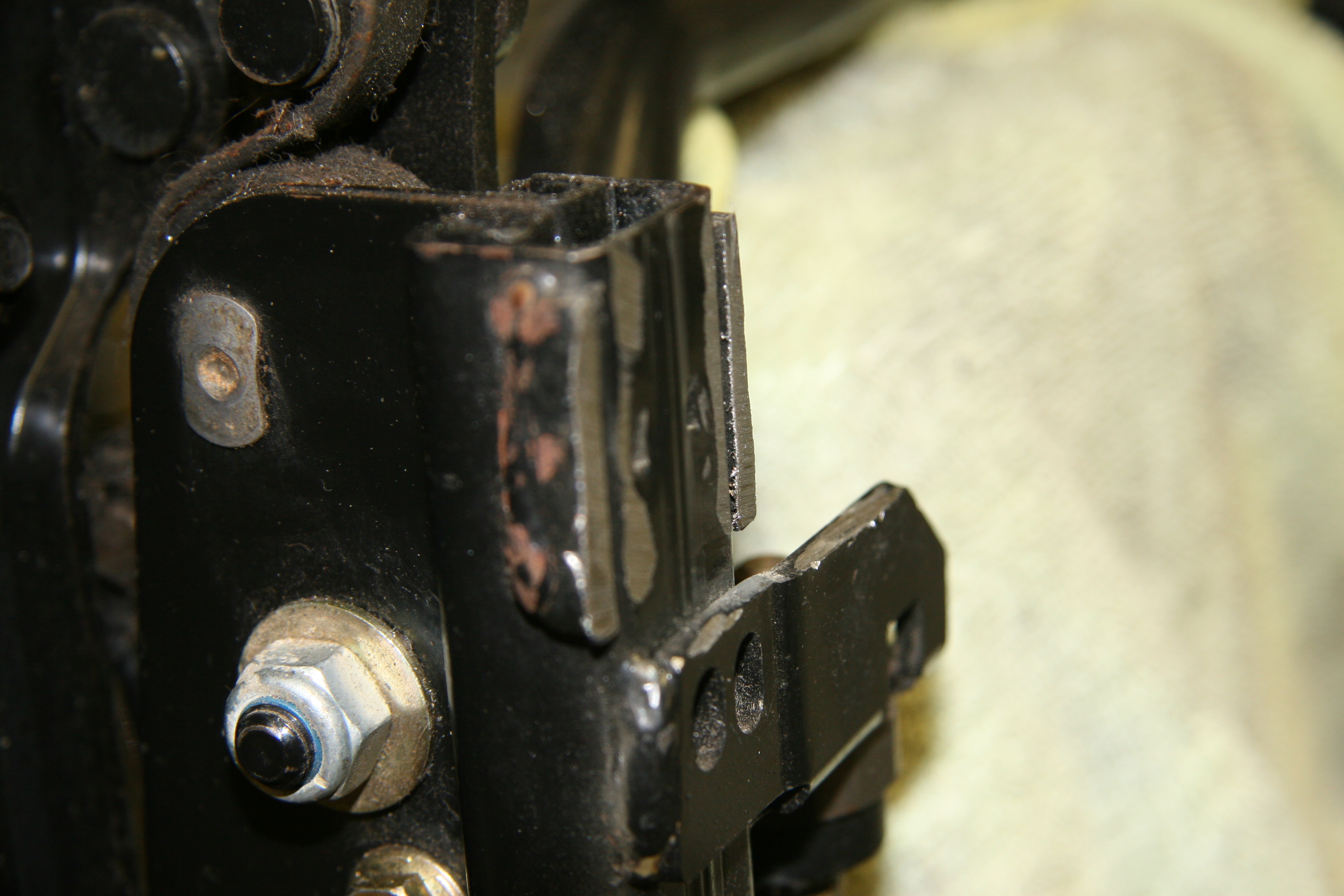
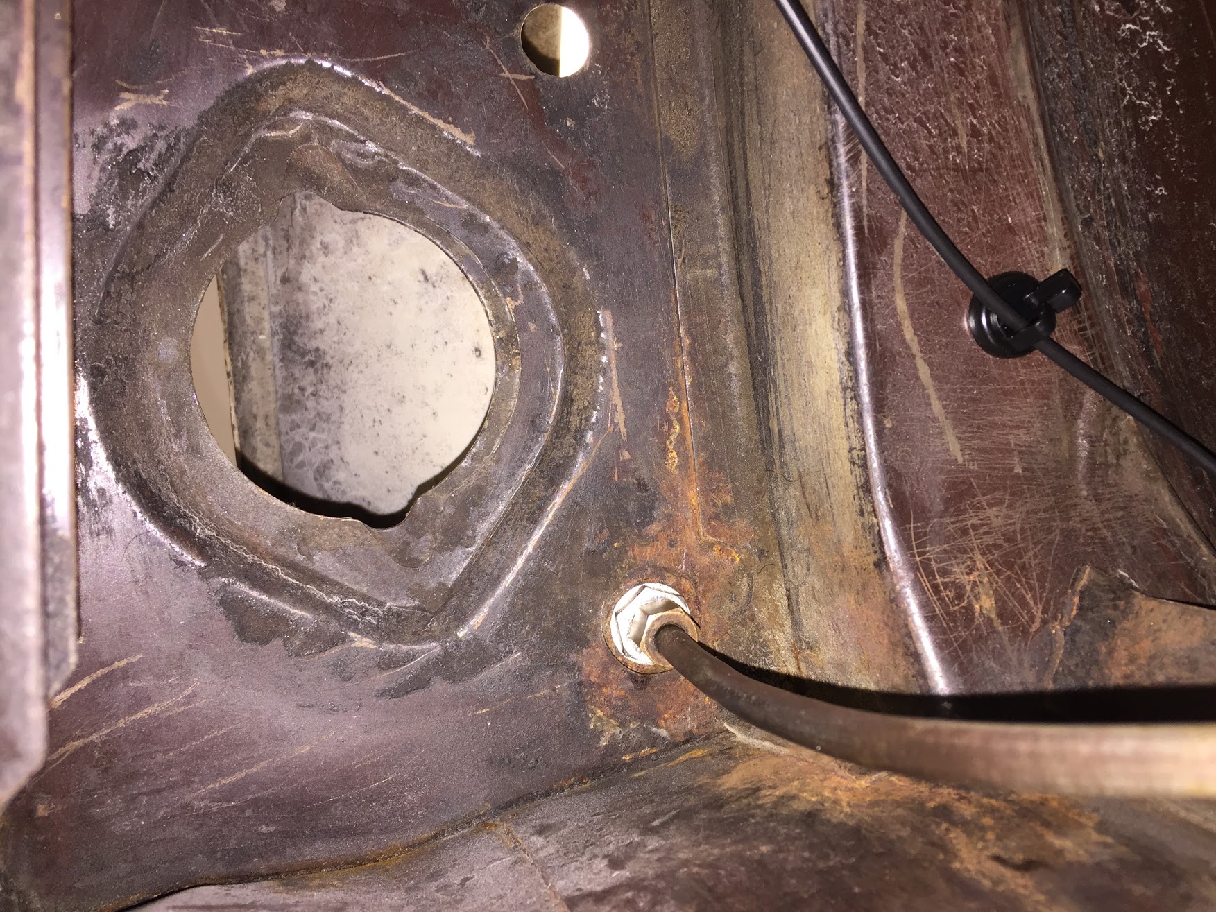
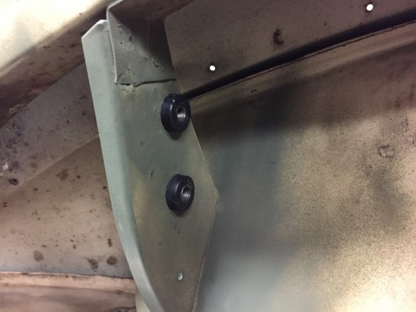
The image below shows these fasteners securing the fuel hard line that travels to the front of the car from the fuel pump. The image was taken from the floor, looking up to the underside of the boot.
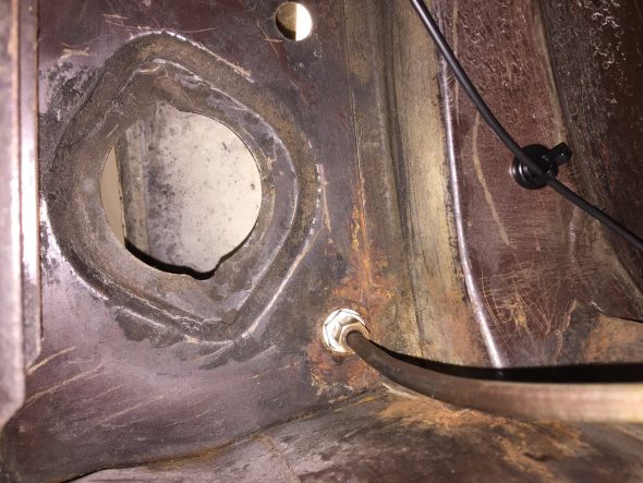
Fuel Connection From Pump to Pipe to Engine Bay
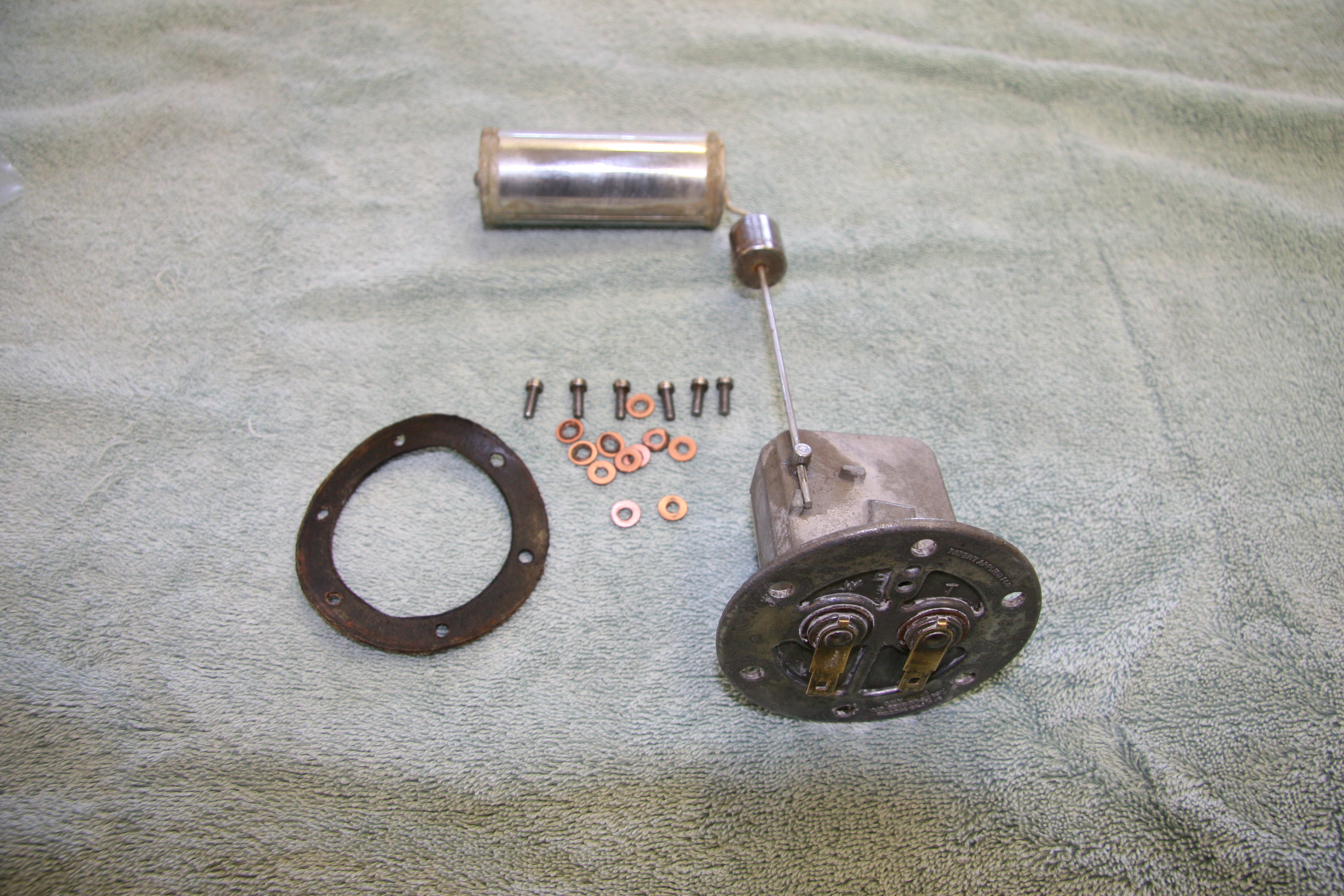
Petrol Tank Element Unit
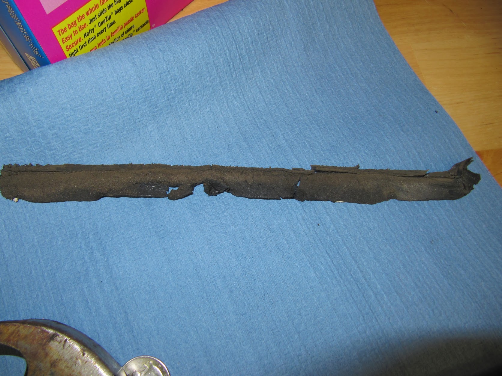
The unit is secured to the tank with six set screws and 12 copper washers and a cork seal. The unit is positioned in the tank so that the float is toward the front of the car. I did check the fuel gauge with my multimeter and found it to be functioning properly. The swing motion of the Petrol tank Element Unit float arm worked just fine and the interior of the units seemed to be clean and without damage so I just cleaned up the exterior of the mechanism and got it ready to reinstall when the time comes. I ordered a new seal.
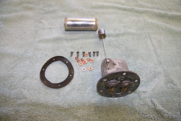
Petrol Tank Element Unit, Seal and Fasteners
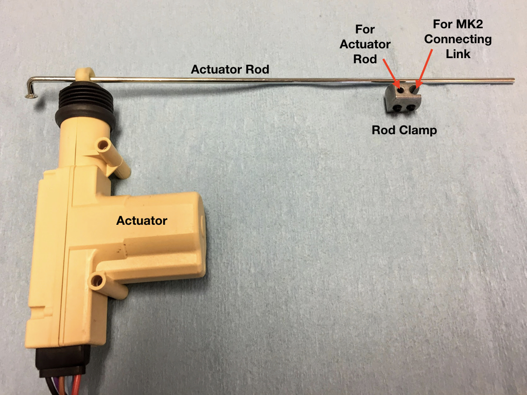
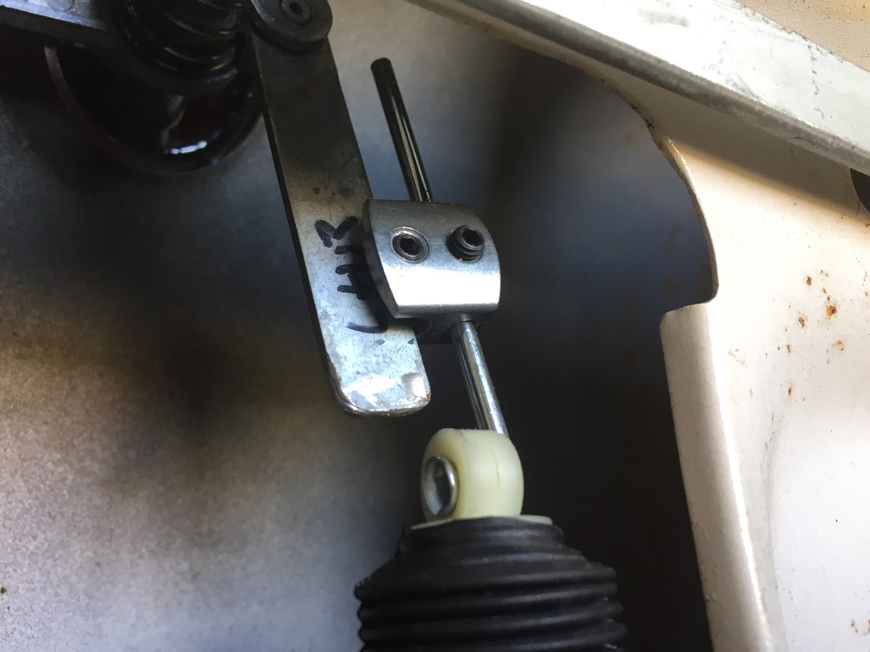
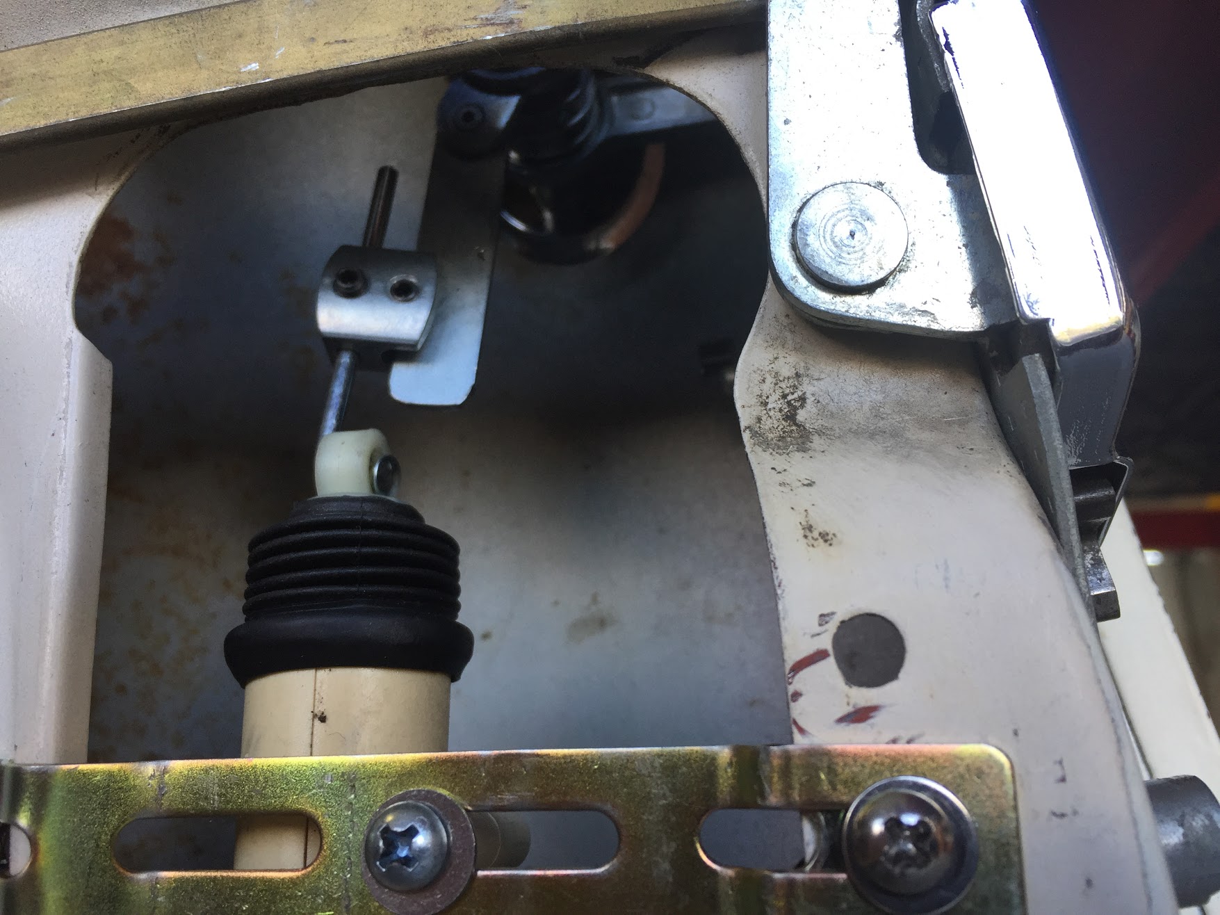
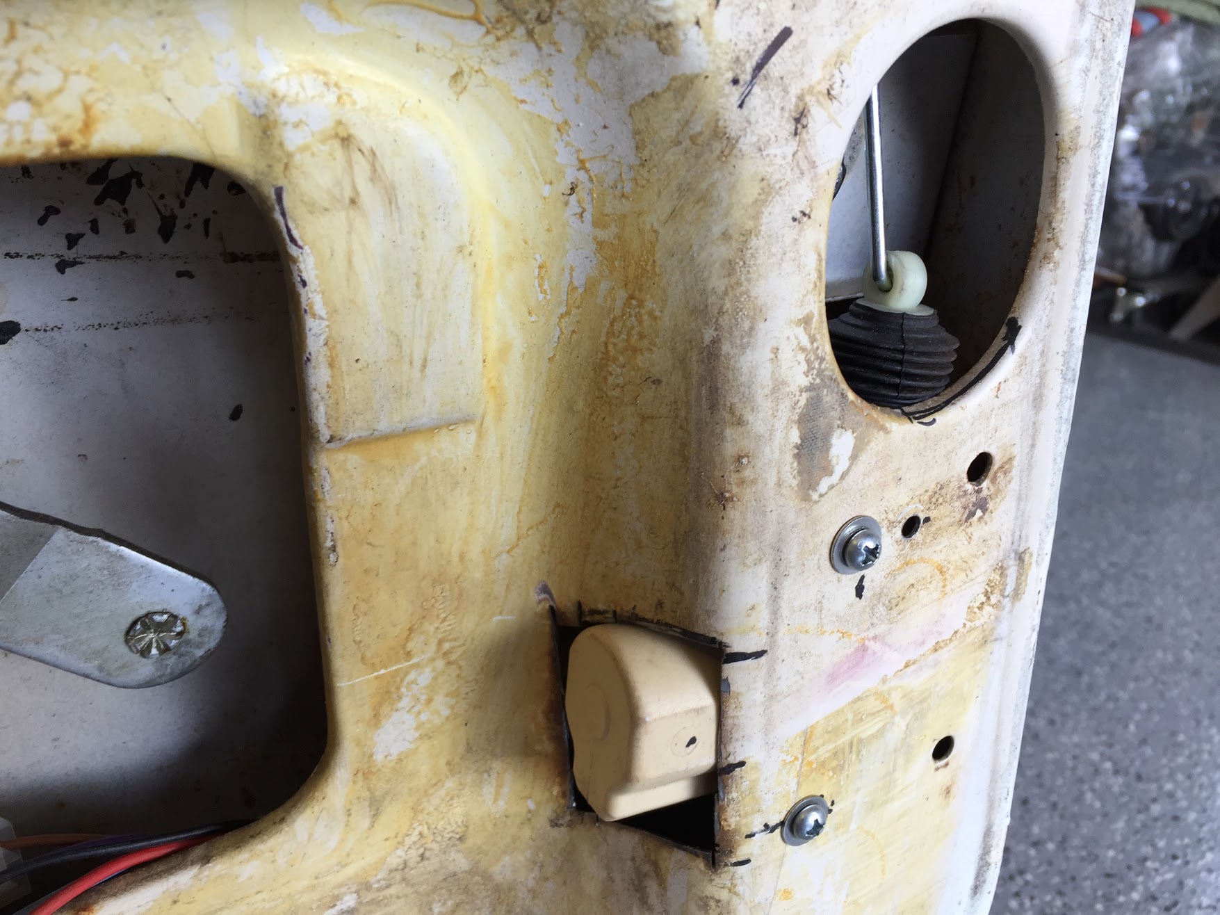
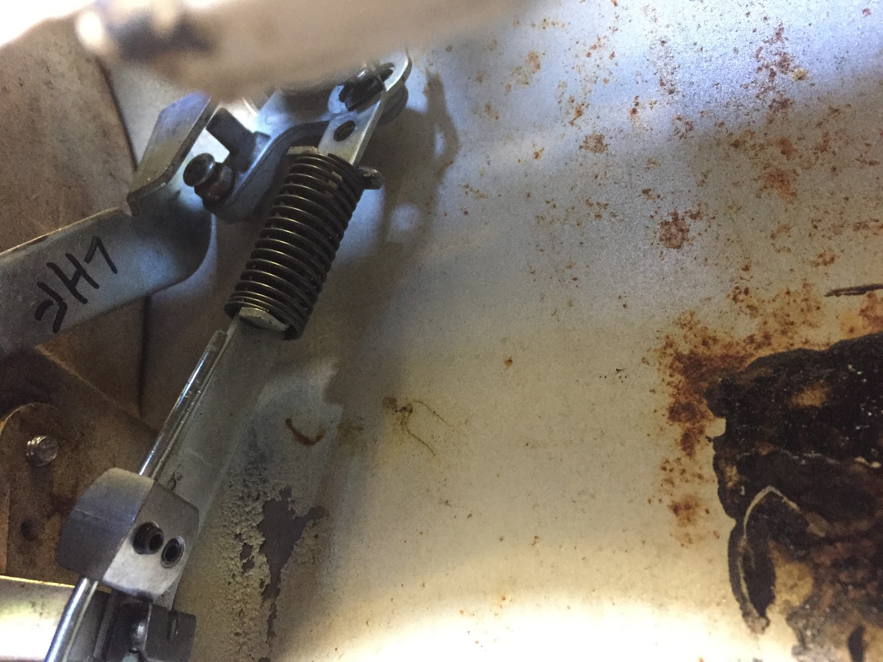
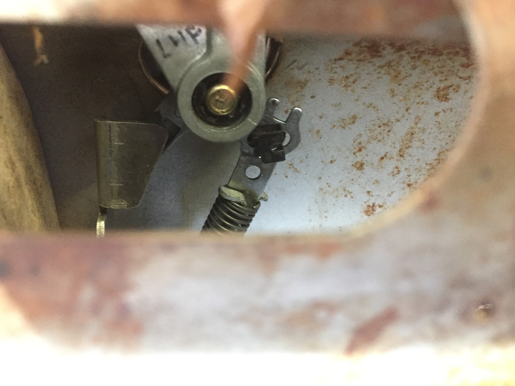
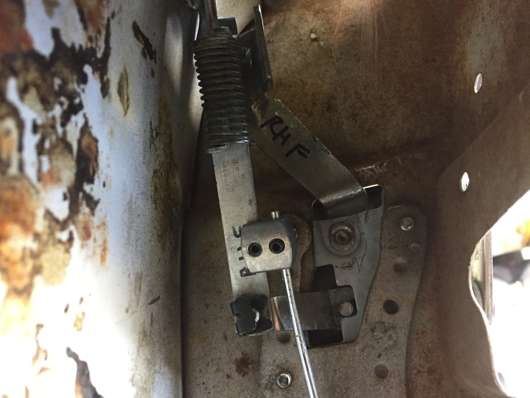
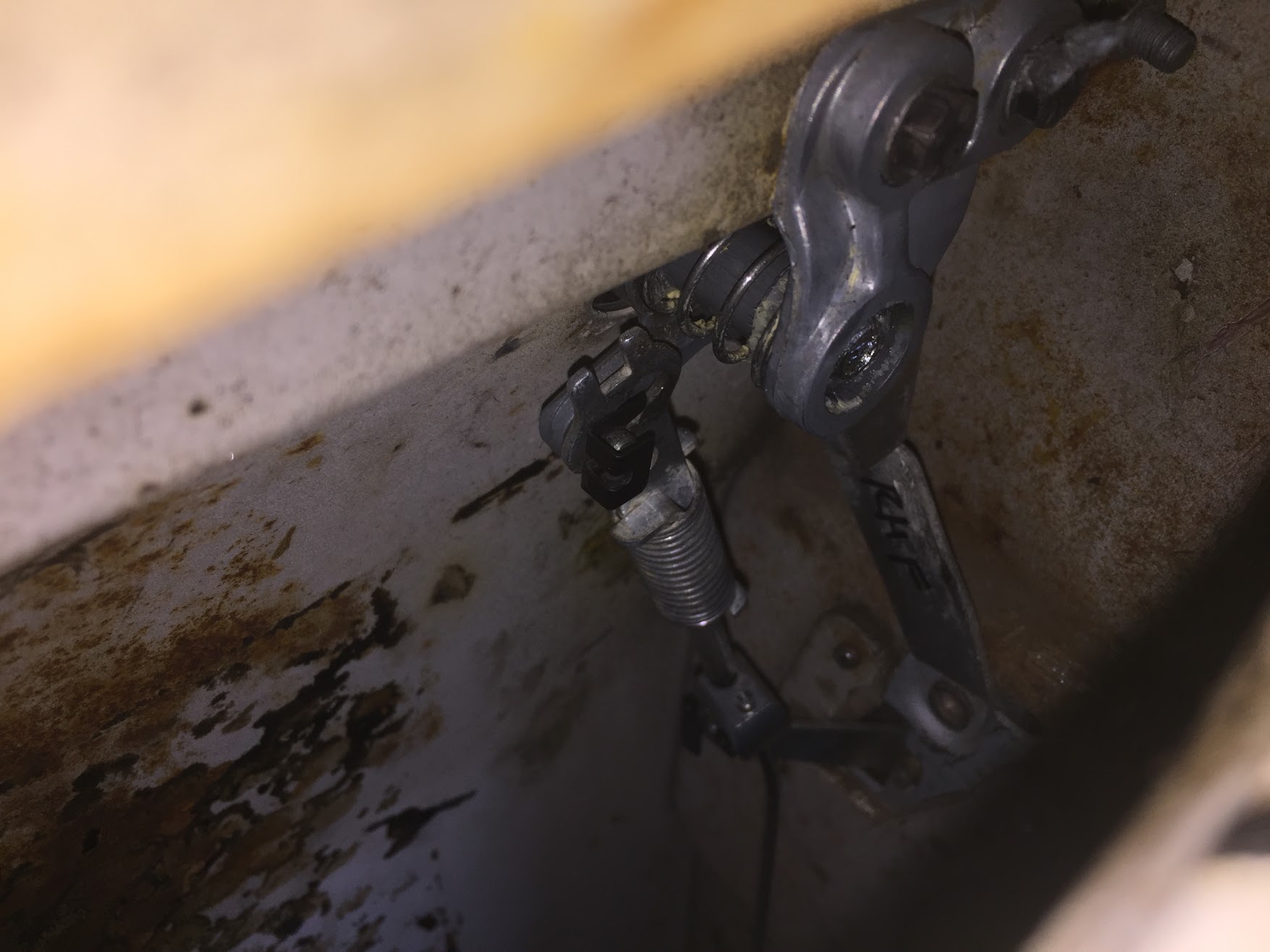
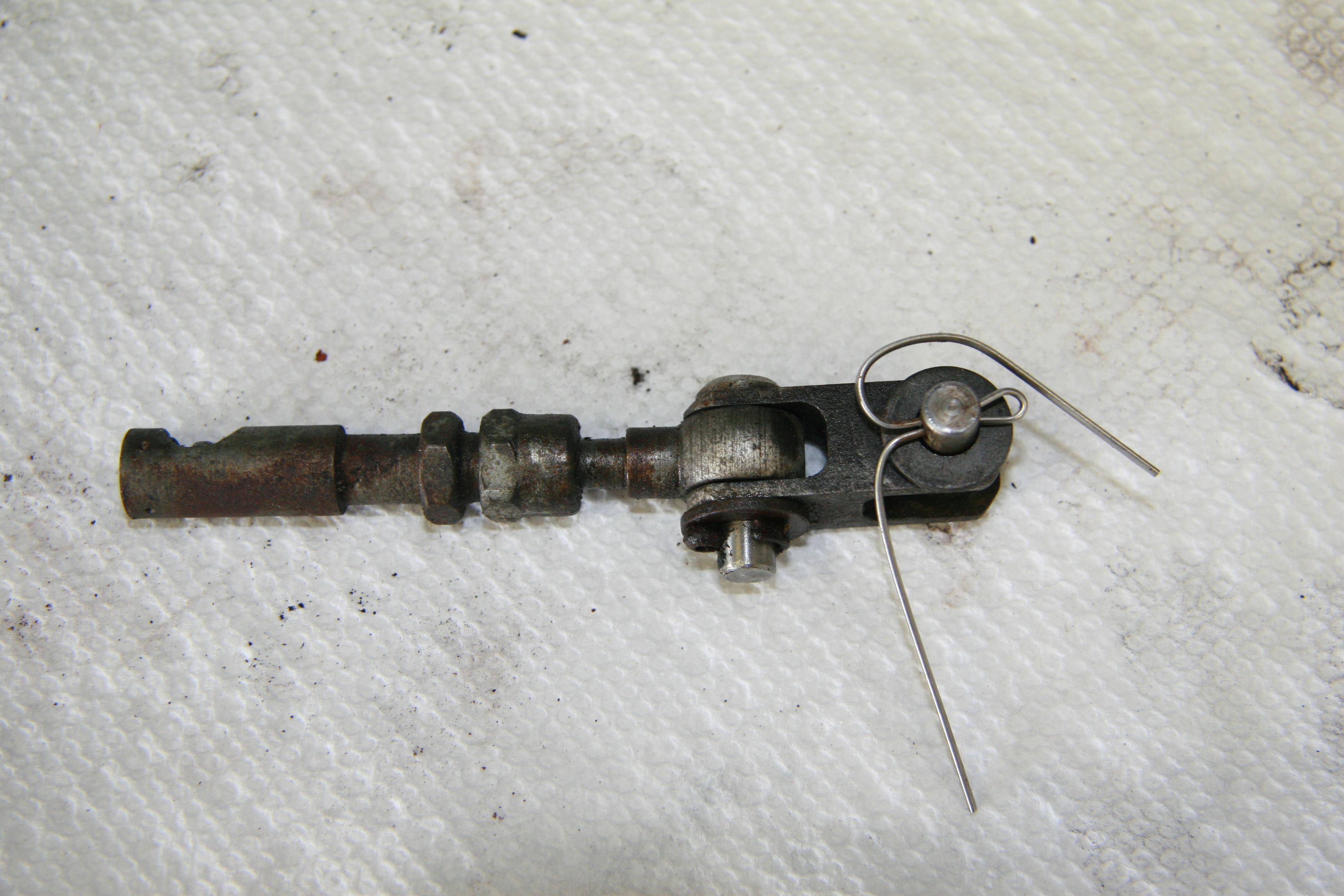
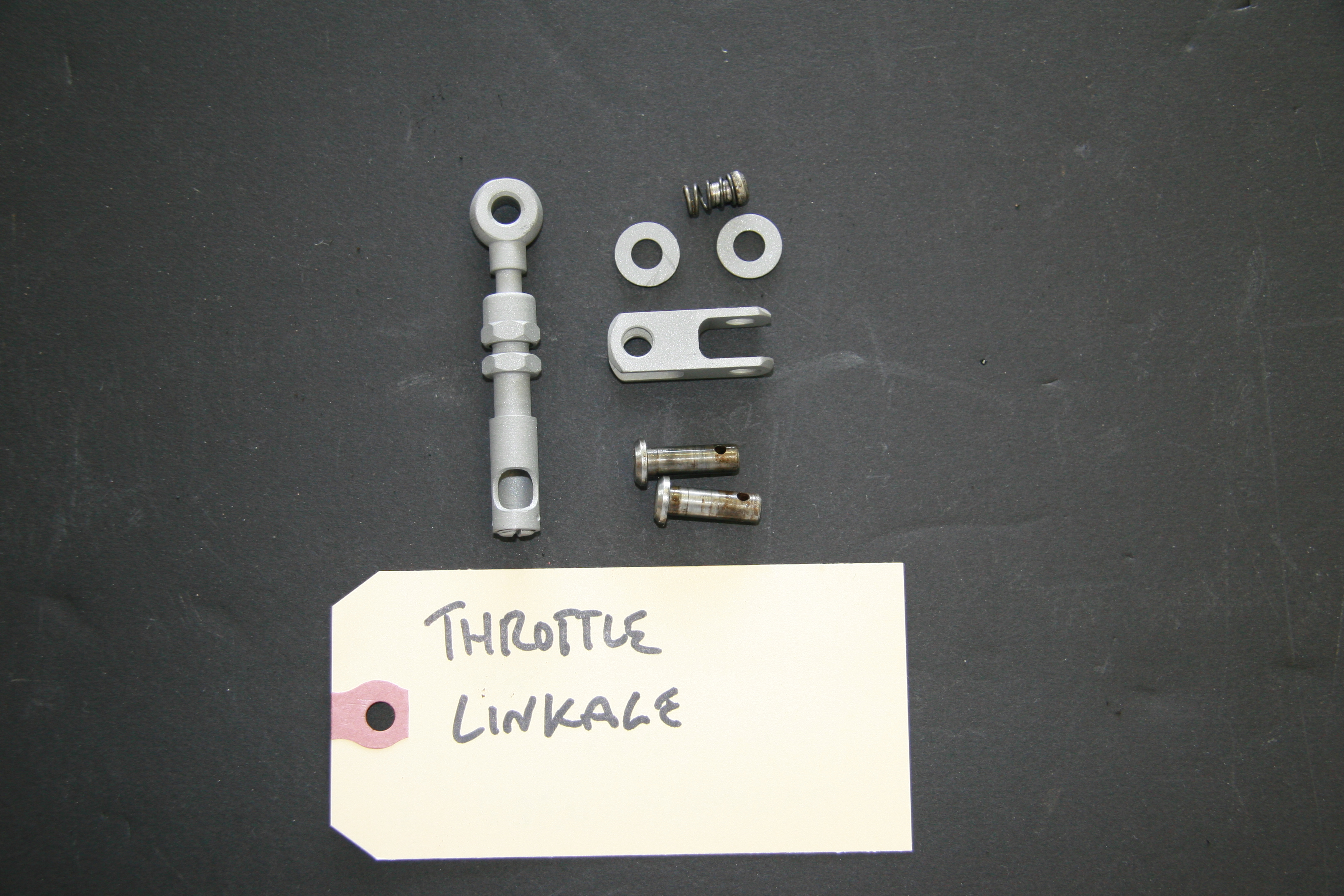
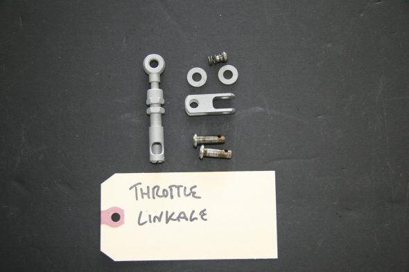
Throttle Link Rod Assembly on Trunnion
I just media blasted this throttle controls component to zinc plate for reuse.
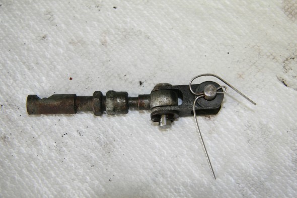
Throttle Link Rod Assembly on Trunnion

Throttle Link Rod Assembly on Trunnion
SU HD6 Carburetors
I am using the original HD6s used on my 3.8 motor. The carbs and all of the hardware were cleaned and inspected by Joe Curto and rebuilt by Mike Gassman. Mike tuned for the run-in, but I will re-tune after the engine is in the car and operating with load. These are tuning instructions located on the Moss Motors website:
SU Carb Tuning
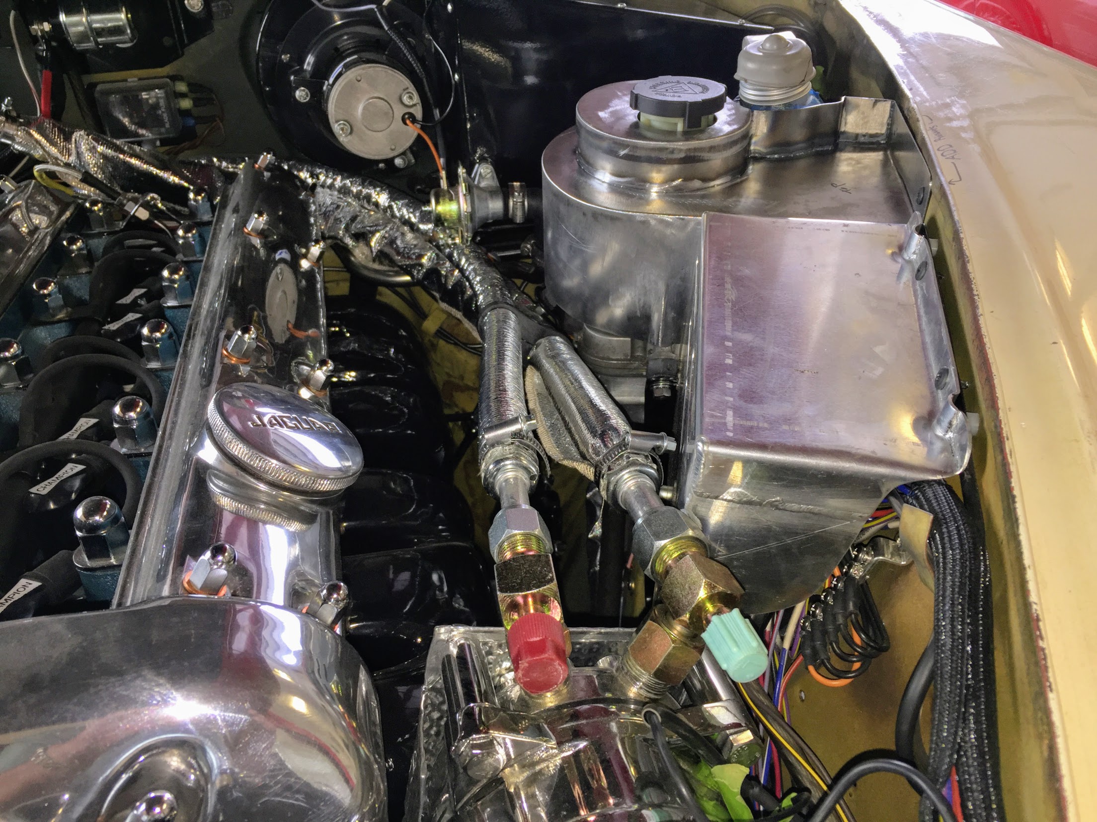
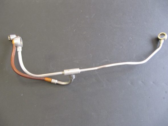
Carburetors Fuel Feed Pipe
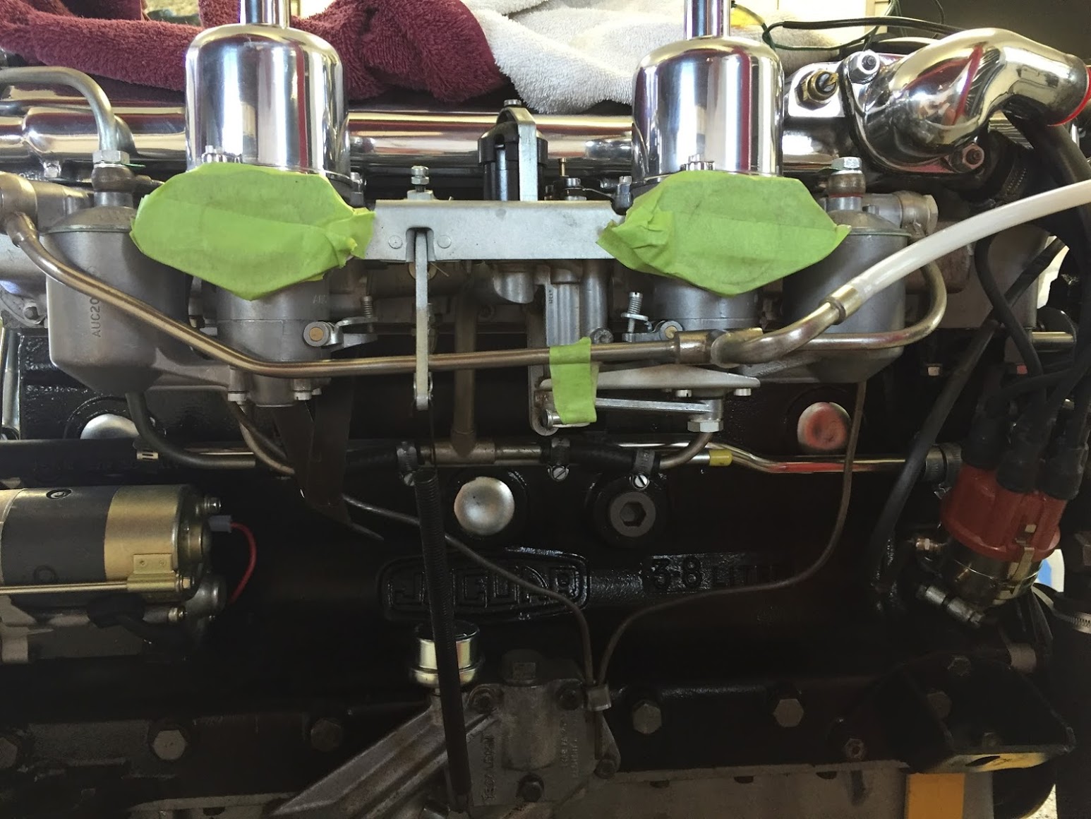
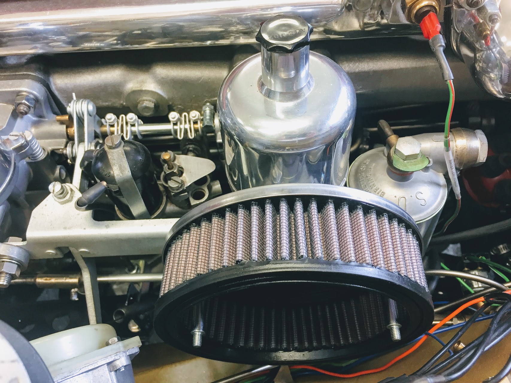
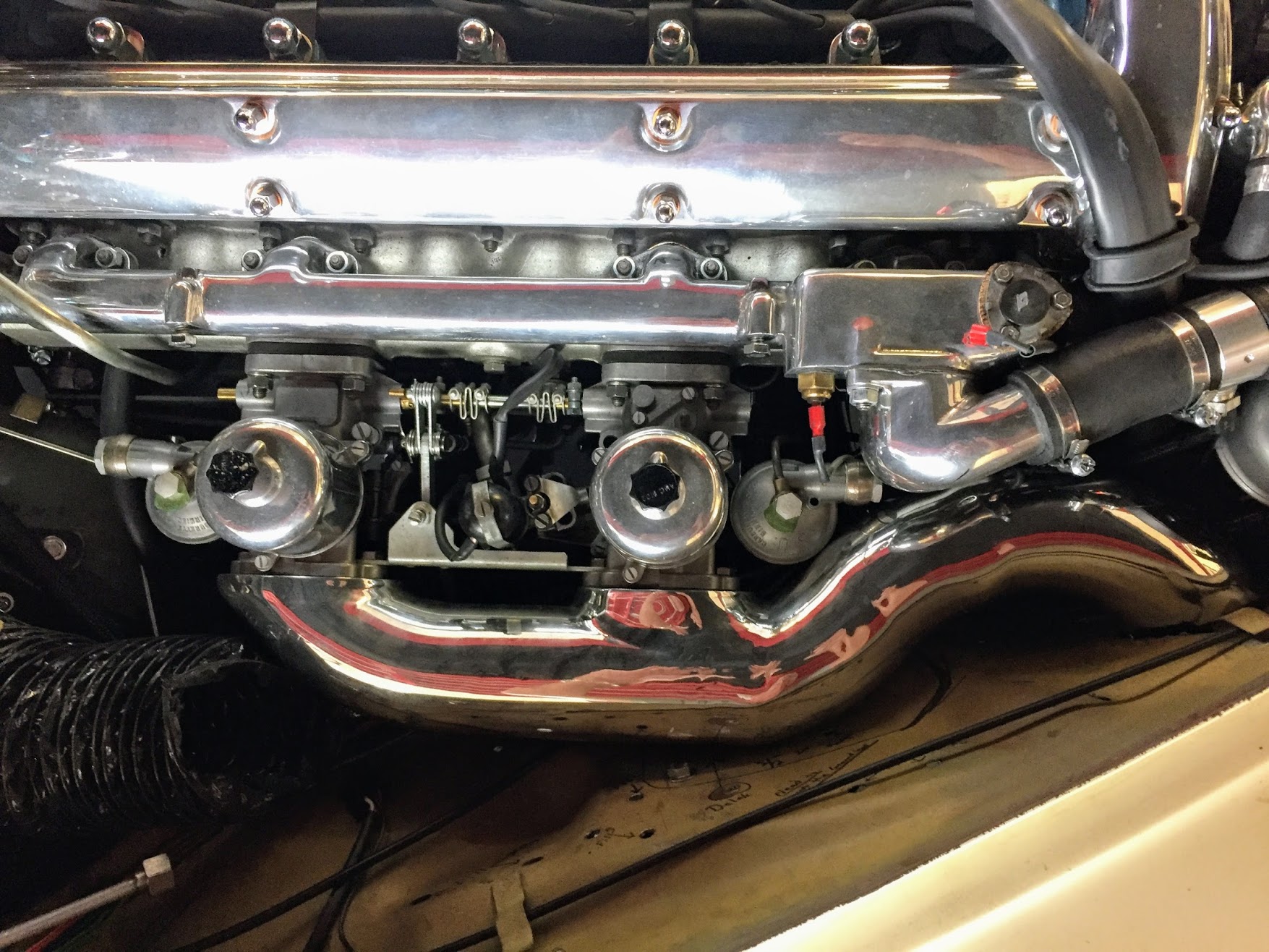
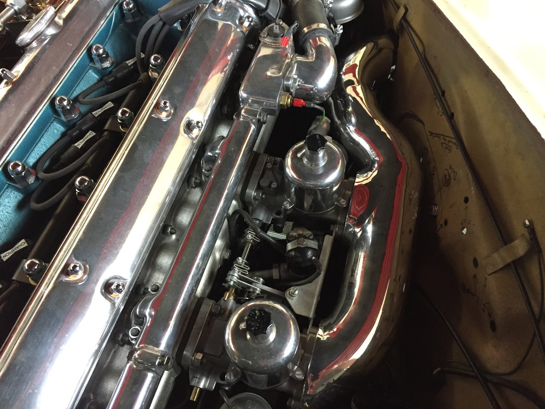
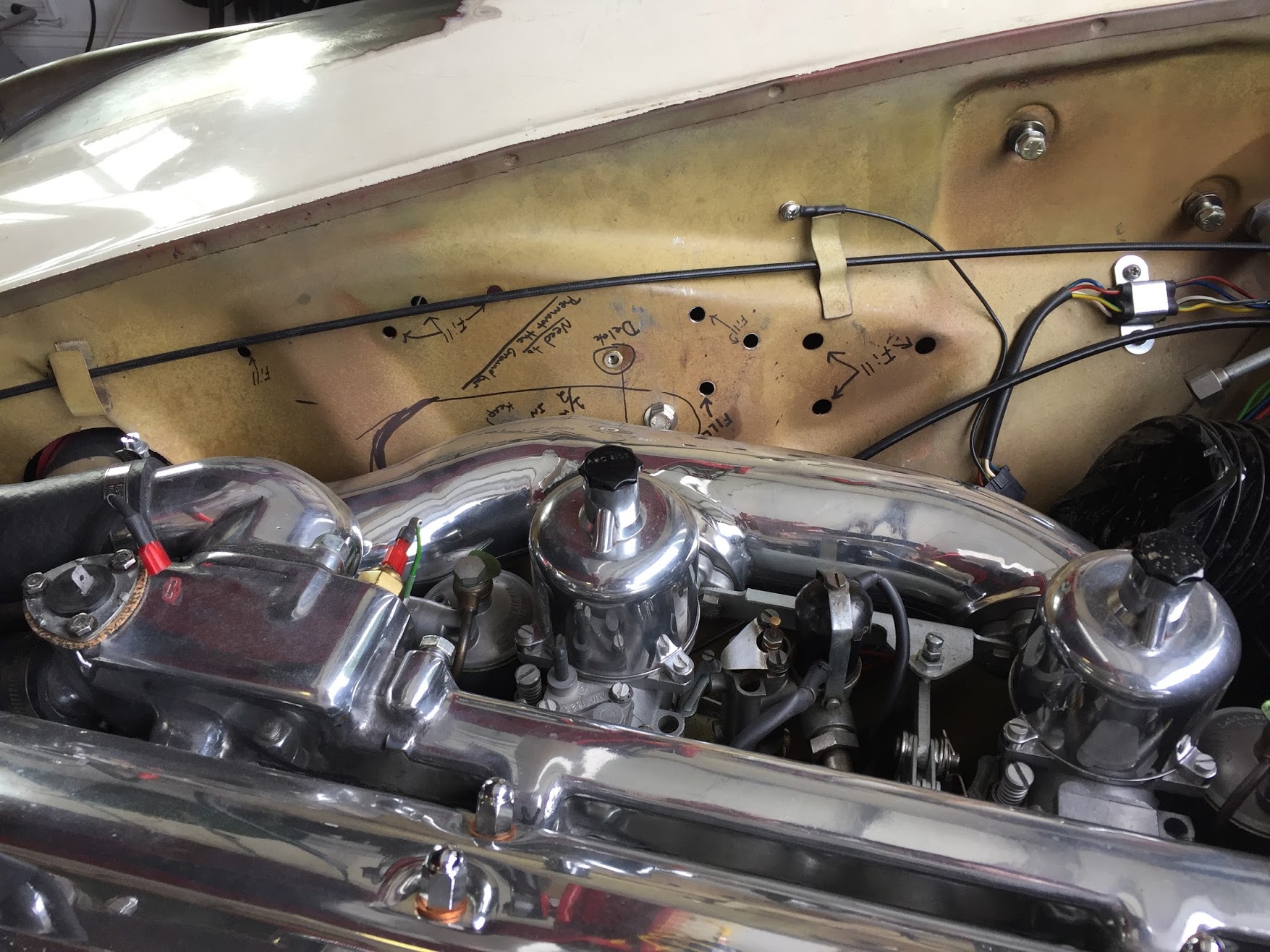
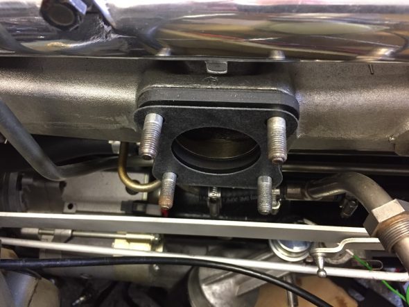
I am not using the original “pancake” air cleaner designed for the 3.8 MK2. I just cannot cover up the beautiful twin cam engine with a big ugly air cleaner, so I will be using small air cleaners located at each carb. This does create a few logistics problems. For starters, the original carb fuel feed pipe junction fitting and flexible line to the fuel filter on the RH engine bay valance conflict with the front air cleaner. This image illustrates the problem with fitting individual air cleaner using the original fuel feed pipe.

Original Fuel Feed Pipe to Carbs
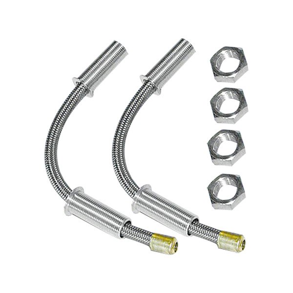
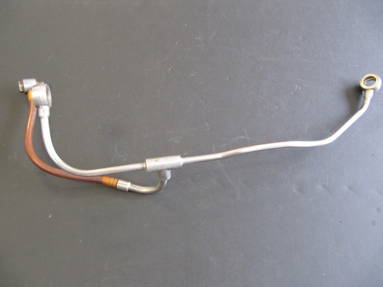
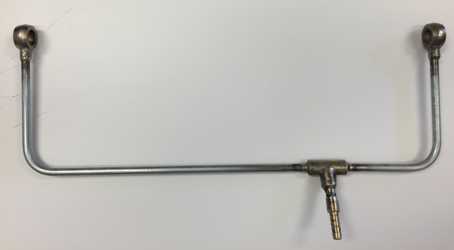
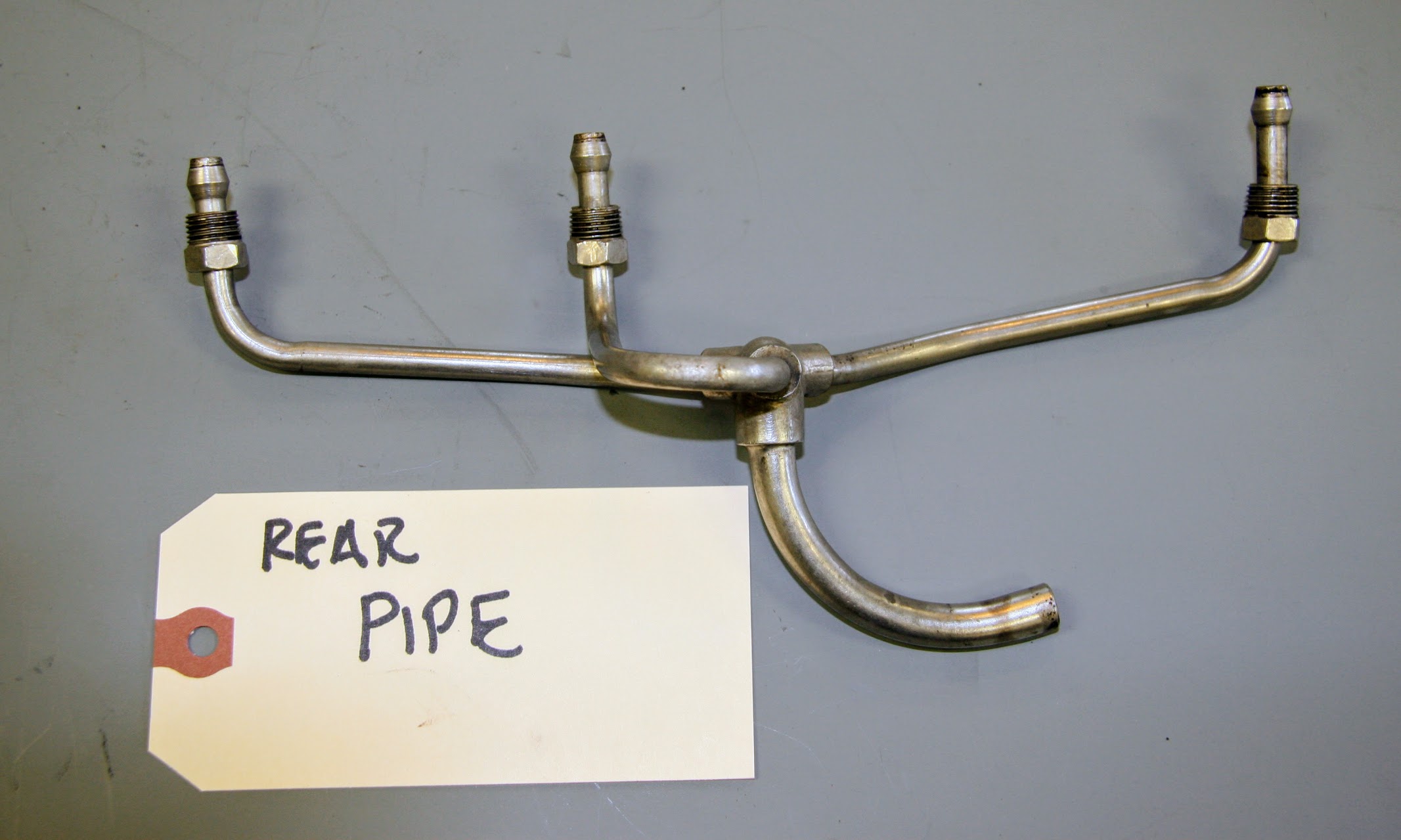
I had a new fuel feed pipe made using the original fittings with a relocated junction to avoid the problem.
Original Carb Fuel Feed Pipe & Fittings
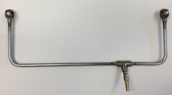
Modified Carb Fuel Feed Pipe
The Auxiliary Starting Carburetor – Otter Switch
The auxiliary carburetor is an enrichment device to make starting the car easier. The unit is actuated by a thermostatic switch (Otter Switch). These switches are notorious for failure; however, Mike Eck, best known for his Jaguar clock repair, upgrades the original Otter Switch by by putting a sealed thermostatic module inside it, so it looks the same as it did originally but works reliably. At the time I had his improvement fitted he charged $45 for the modification.
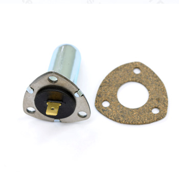
Otter Switch
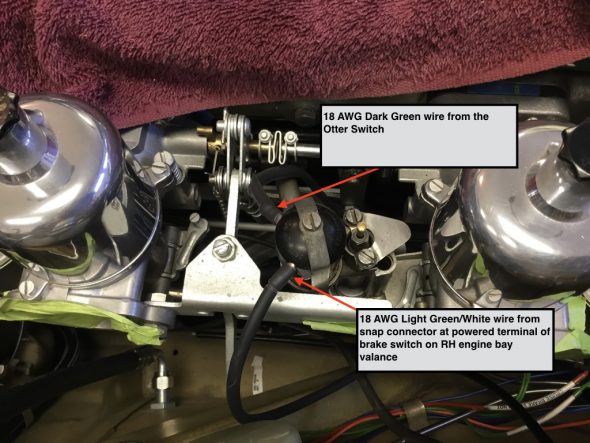
The electrical connection from the otter switch to the solenoid of the enrichment carb is achieved with a dark green 18 AWG wire in a rubber sleeve.
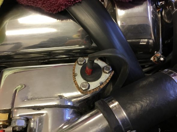
Otter Switch Electrical Connection to Auxiliary Starting Carb
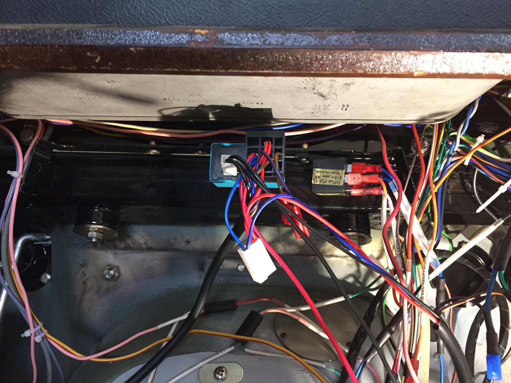
The thermostatically controlled enrichment caburetter is actuated by a solenoid. The additional electrical connection for the solenoid comes from a four way snap connector on the RH engine bay valance. The connector joins the 18 AWG light green/white from the enrichment carb solenoid with the wire emanating from fuse position #22 to the brake switch. In other words, the starting carb gets its power from the powered side of the brake switch located on the RH engine bay valance.
Trial Installation Update
Carburetor Mounting
I installed the carbs as an assembly. I loosened the couplings between the connecting rod and the throttle spindles, fully closed each butterfly and then secured the couplings. In my case because I am not using the original air cleaner, I had to remove the dowel bolts that connects the throttle stop bracket between the front and rear carbs. I replaced the dowel bolts with 5/16″-24 x 1″ hex head bolts and nuts. After the carbs were mounted to the inlet manifold I removed the two nuts and the 1″ hex head bolt was then used for the installation of the air cleaner.
Before mounting the carb assembly on the inlet manifold I first installed one gasket (c.7221), then an insulator block (C.8486) and then another gasket (C.7221) on the four 5/16″-24 inlet manifold studs for each carburetor.
Gaskets and Insulator Blocks between Carb Bodies and Inlet Manifold
I then mounted the assembly and securely tightened split washers and nuts on each of the eight studs. Before tightening the two nuts/washers on the lower studs of the front carburetor, I reinstalled the bracket assembly for the throttle return spring anchorage. I cleaned and painted the bracket but this is what it looked like prior to “clean-up.”
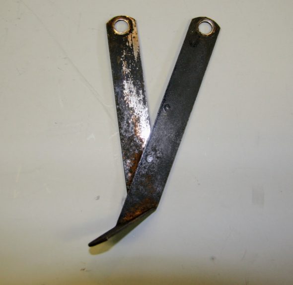
Bracket Assembly on Front Carburetor
Fuel Delivery
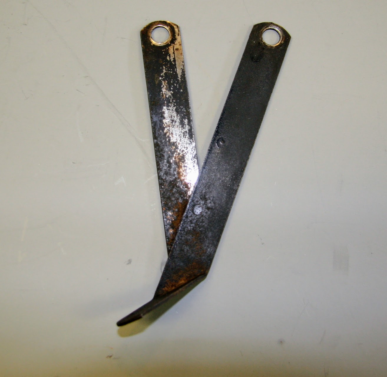
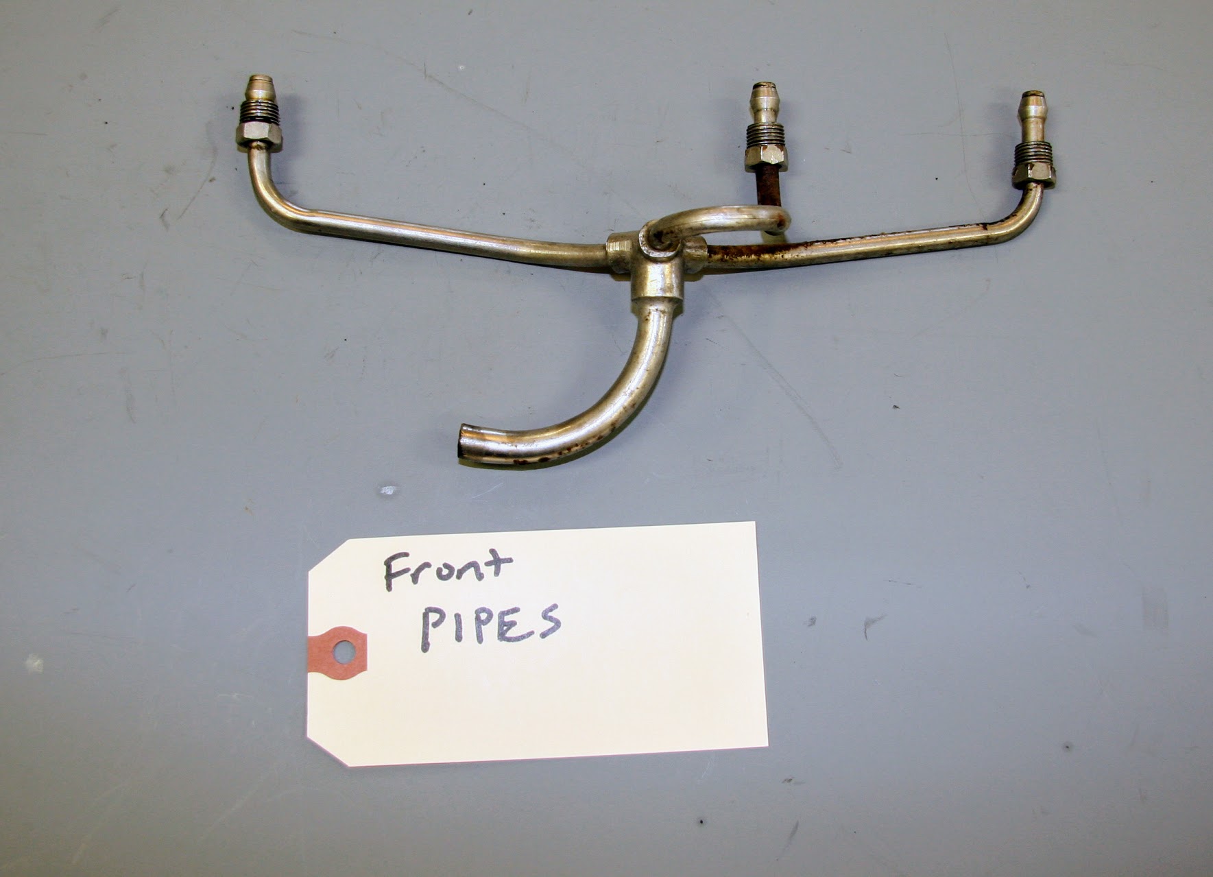
After the carburetor assembly is mounted on the inlet manifold, the starting pipe assembly is connected with two short pieces of neoprene fuel hose requiring four Jubilee Hose Clips. I don’t have a good photo of the staring pipe full assembly, but these are the three components that screw into the underside of the inlet manifold.
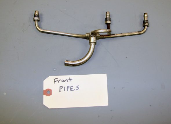
Front Manifold Starting Pipe Assembly
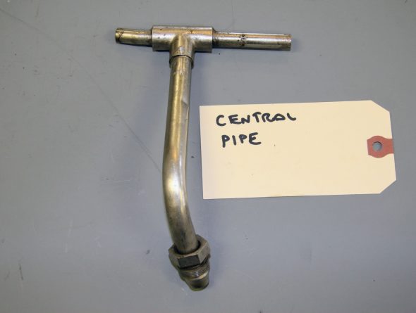
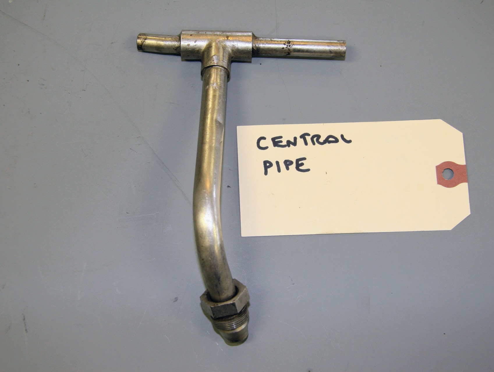
Center Manifold Starting Pipe Assembly
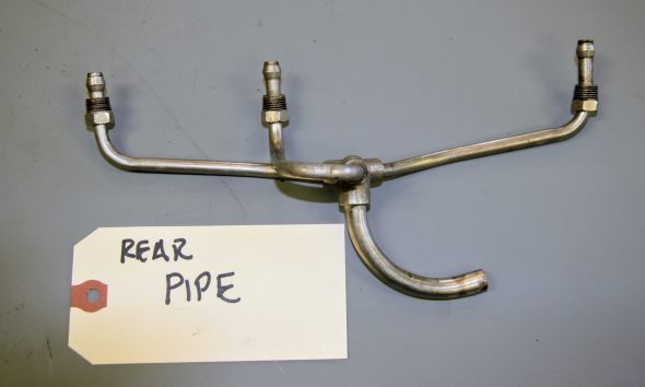
Rear Manifold Starting Pipe Assembly
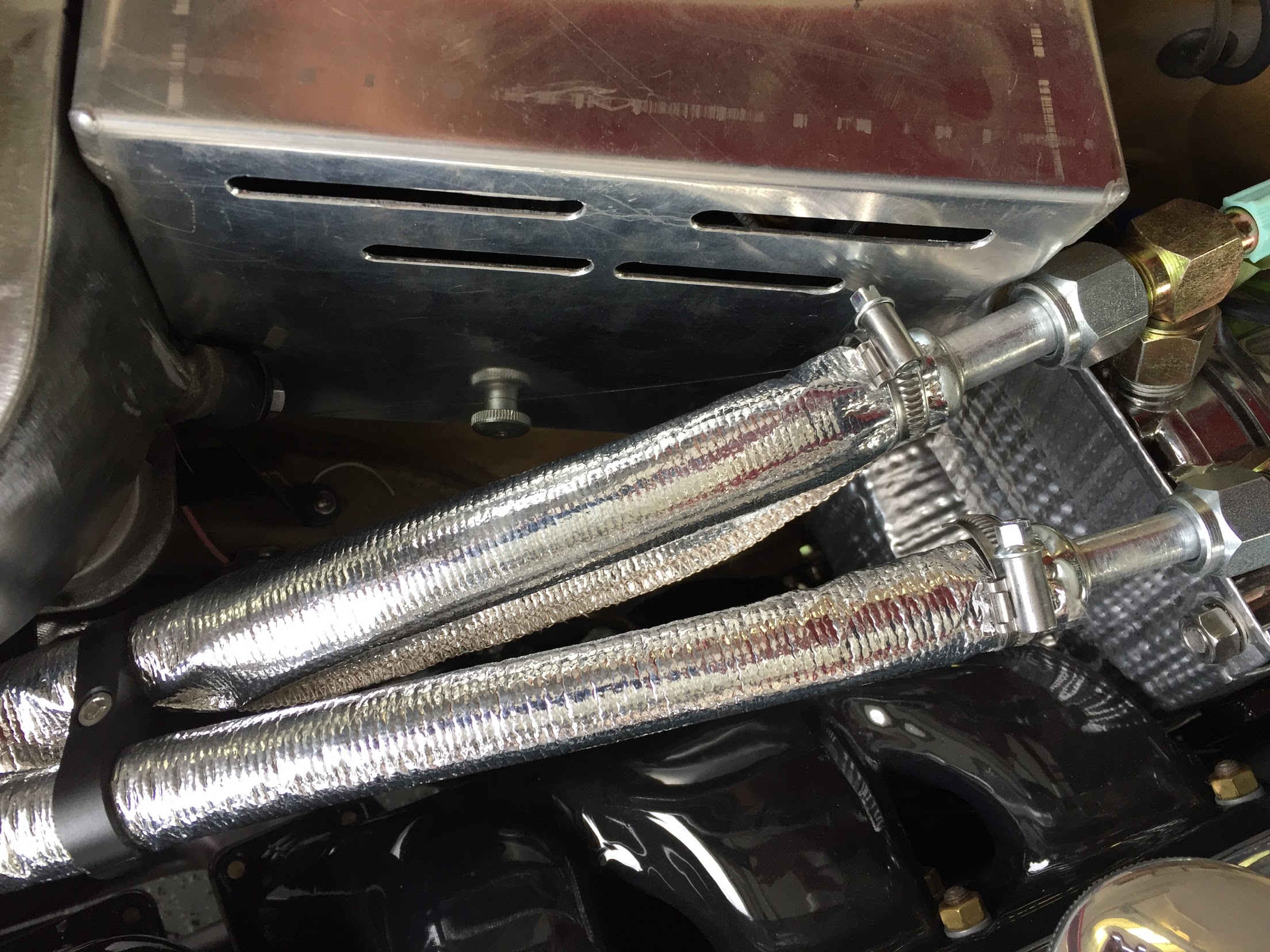
The neoprene hose connections are not simply made and must be done from below the car. These can be seen in the photo below, although they are somewhat difficult to ascertain. The photo was taken from below the car.
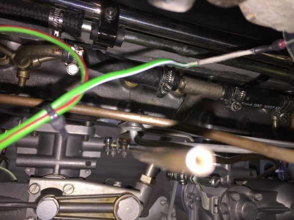
Manifold Starting Pipe Assembly Fuel Hose Connections
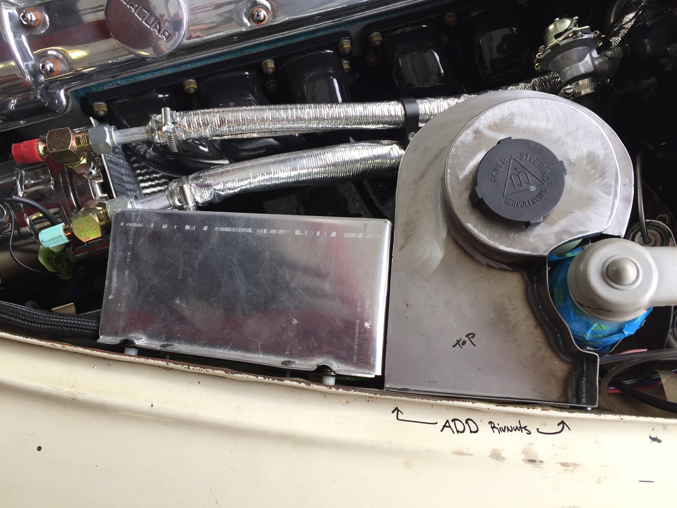
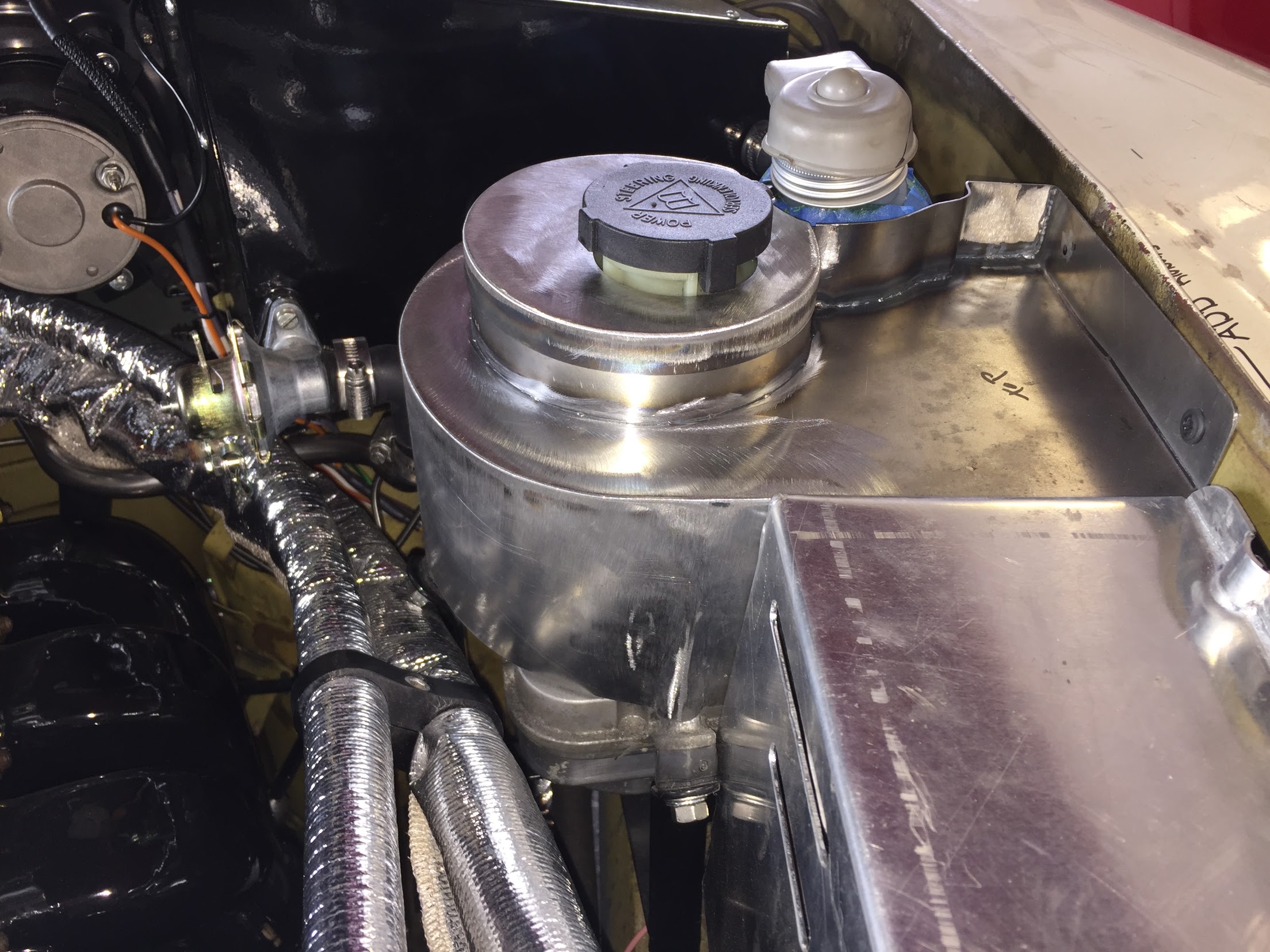
I have decided to move the fuel filter from the engine bay.
I am sure that the original design is perfectly fine, but I was never fond of Jaguar’s placement of the fuel filter on the RH engine bay valance. The filter has a glass bowl that is functional permitting easy viewing of fuel flow and any sediment caught by the filter, but I am leary of fuel in glass in an engine compartment. With no insulation, the fuel is also subject to “boiling” after the engine has been run and then parked due to residual engine heat.
Eliminating the original AC fuel filter from the engine bay also gives me some much needed room under the bonnet. With my modifications including air conditioning, power steering, and carb mounted air cleaners among other items, space in the engine bay is at a premium.
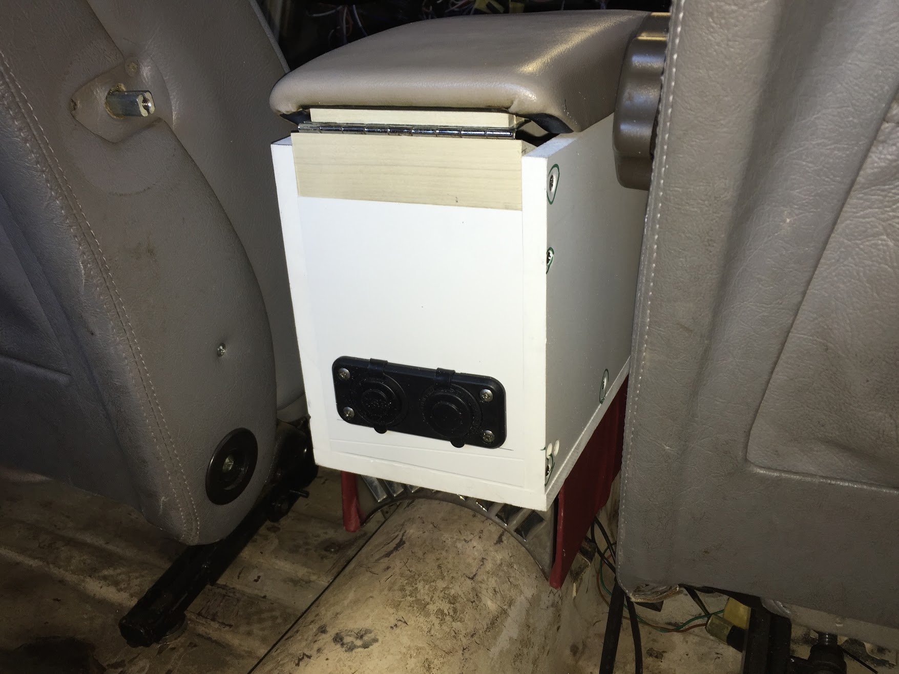
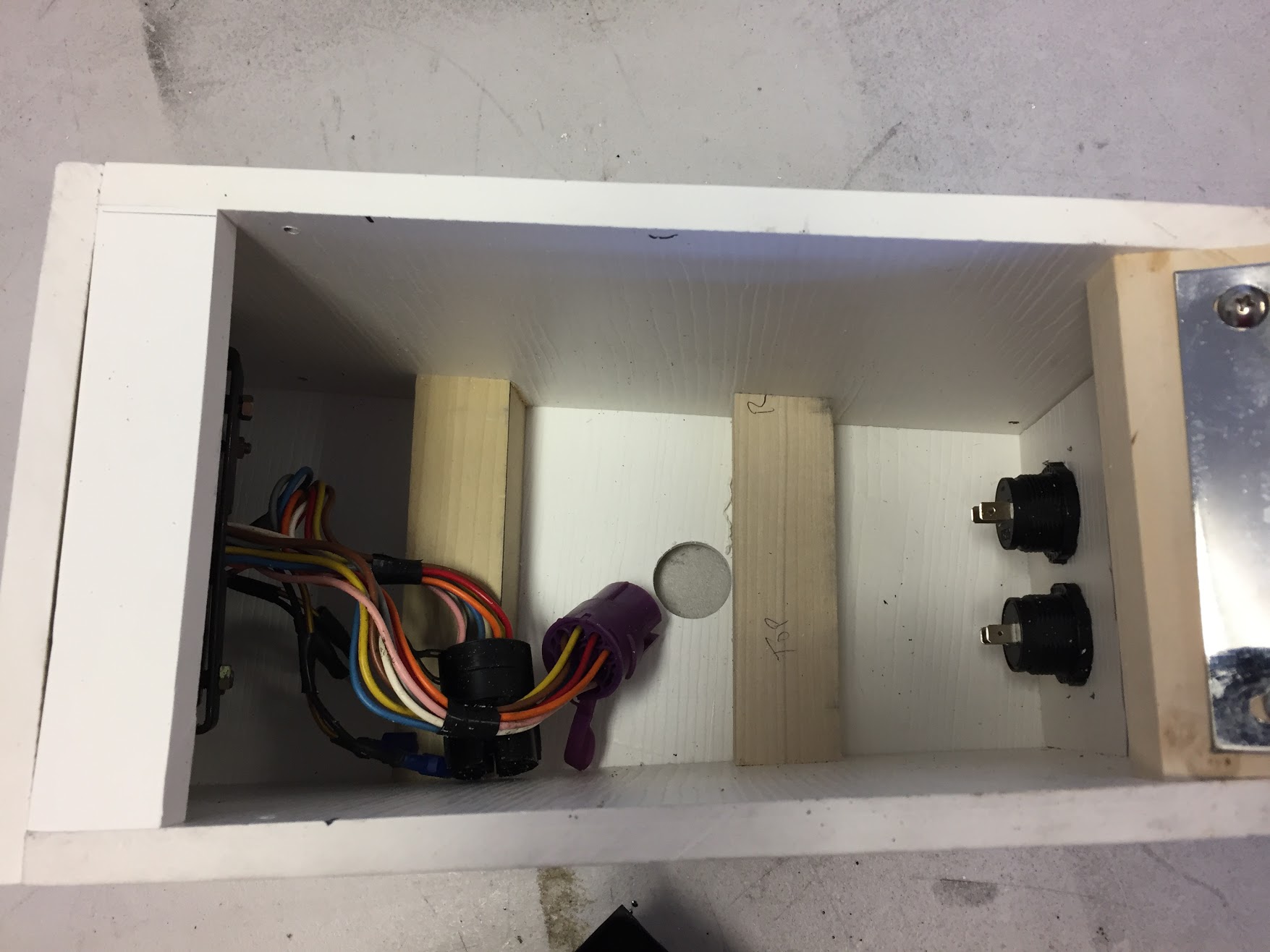
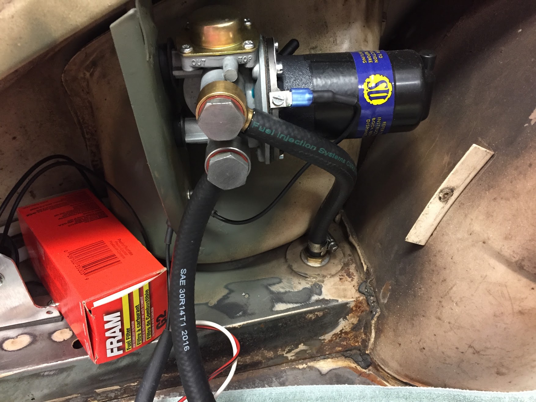
Jaguar located the petrol pump in the LH side of the boot and I decided to do the same with the fuel filter. I will install a Fram G-2 opaque plastic filter between the fuel tank and the fuel pump.
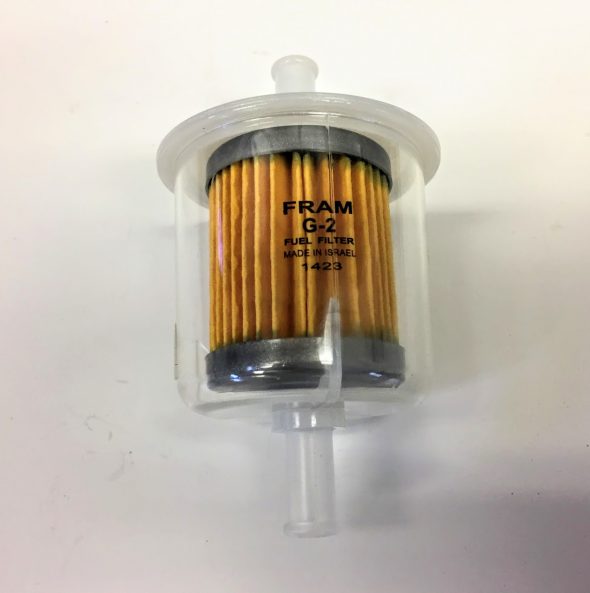
Fram G-2 Fuel Filter
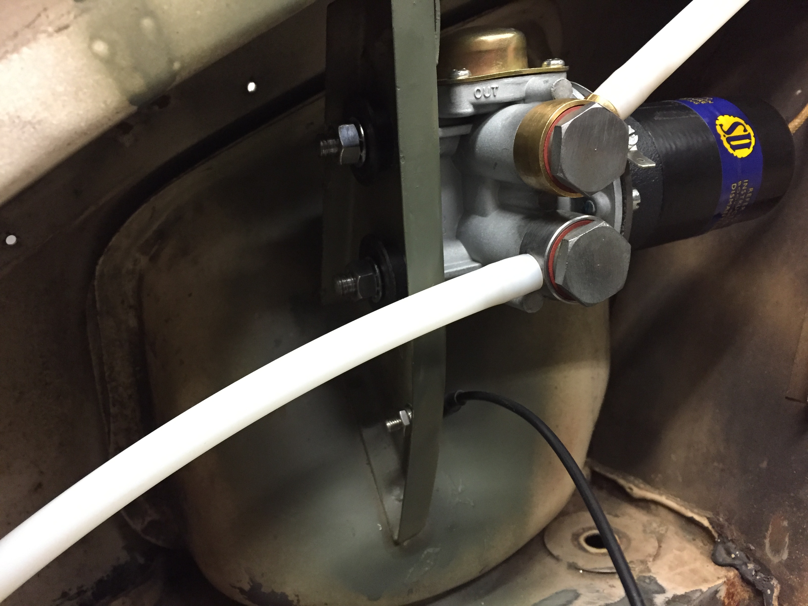
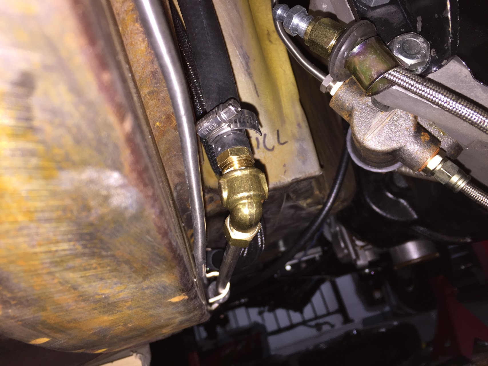
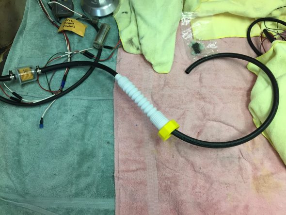
I cut the long 5/16″ steel fuel line that travels along the RH frame rail from the rear of the car to the front slightly above, but near the oil filter. I installed a ninety degree elbow female compression brass fitting to the end of the fuel line. Holyoke P/N 70-54, 5/16 compression to 1/4 NPT. The elbow is attached to a male 1/4″ NPT to 5/16″ barb fitting. I then ran a 5/16″ ethanol resistant rubber fuel hose from the barbed fitting to the barbed fitting on the carburetor fuel delivery pipe. Used two 11-16mm jubilee hose clamps.
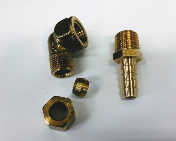
Brass Connection Hardware from Fuel Pipe to Rubber Fuel Hose

Fuel line from tank is connected to the rubber fuel hose that is routed to the Caburetters
A Jubilee Hose Clip is used to tighten the hose on the barbed fitting.
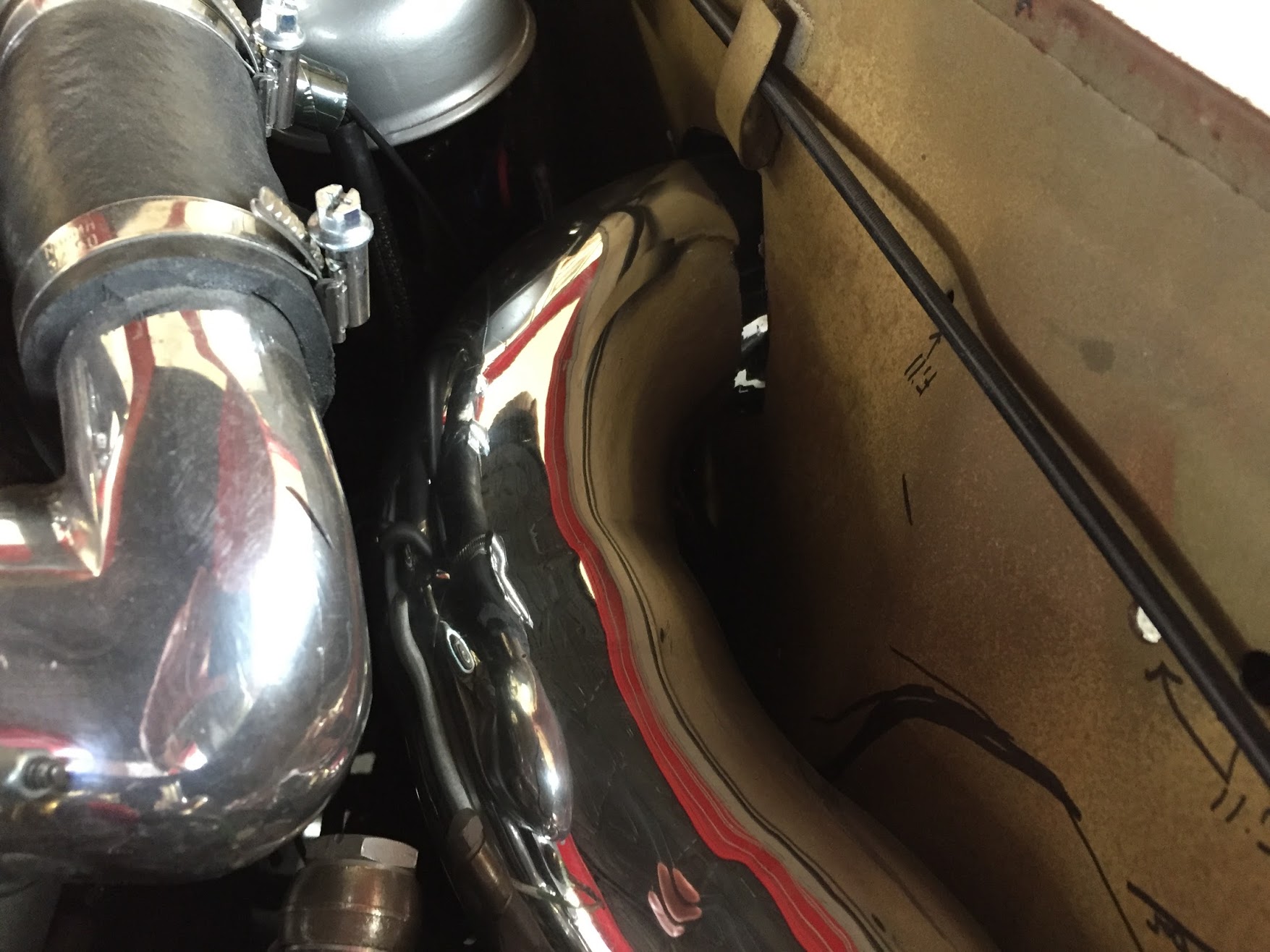
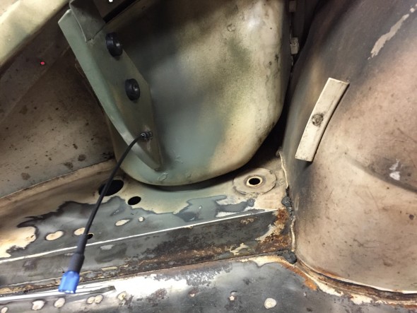
The image below shows the new rubber fuel hose running from the head fuel line under the car to the carburetor fuel feed pipe.
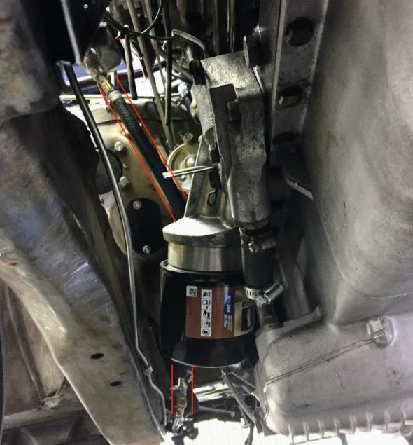
Fuel Hose from Carb Fuel Feed Pipe to Hard Pipe from Tank
Throttle Return Springs
With all of the fuel delivery hose connections made, I then attached the throttle link rod assembly on trunnion – part #81 in the schematic to the bell crank lever assembly from the accelerator controls and tightened the securing screw holding the ball joint together.
Throttle Link Rod Assembly
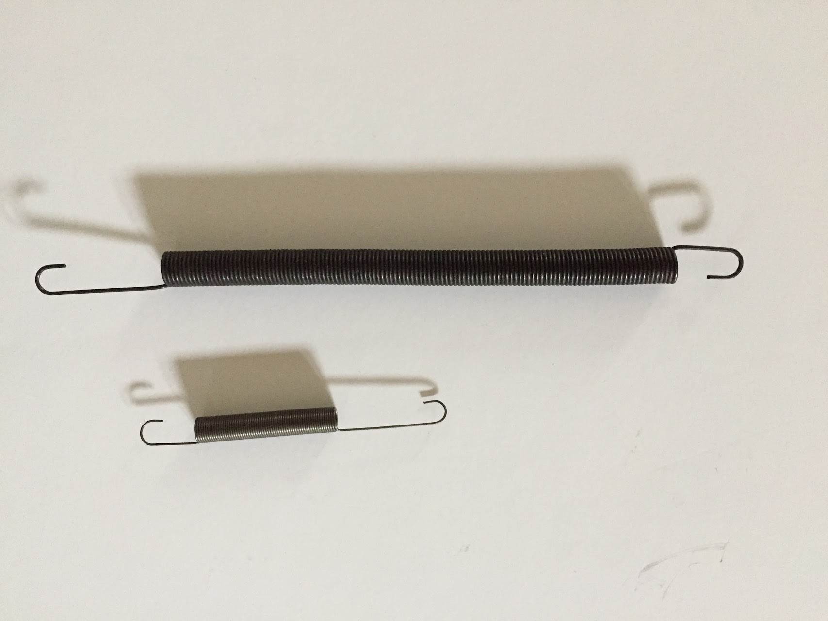
I then moved onto the throttle return springs. The shorter spring is the return spring from the lever on the front carburetor to the anchor bracket mounted below the front carburetor (photo shown above). The longer spring is the return spring from the linkage to the Bracket on the Oil Cleaner.

Throttle Return Springs
My next step was to loosen the two float chamber overflow pipes at the float bowls so that the pipes could be aligned and routed through the clip near the oil filter.
Air Cleaners
As previously mentioned, I am using carb mounted air cleaners rather than the original contraption that I am confident worked well but completely covered up the beautiful twin cam engine. After experimenting with a number of options, I settled on air cleaners sourced from Advanced Performance Technology (APT) http://www.aptfast.com. These air cleaners use K&N Filters.

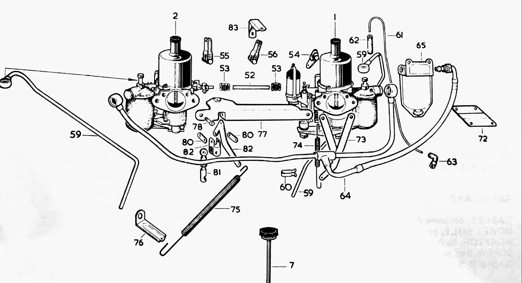
Carb and Fuel Connections Schematic
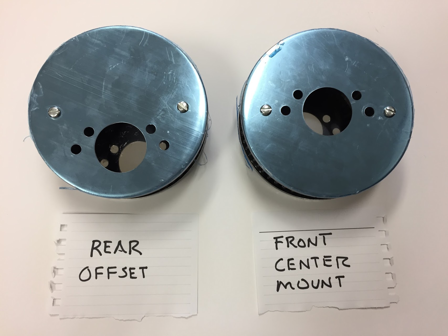
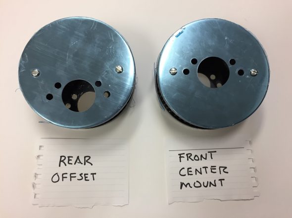
The “intermediate throttle lever from throttle link to stop bracket” – part# 82 in the diagram – on the MK2 carb set up is offset to the rear of center. This requires a comparable offset in the air cleaner mounting to avoid the throttle lever striking the air cleaner casing as it travels its logical path.
I used filters that are 1-3/4″ tall. The rear cleaner is offset upward and is part number: SD24-318 for HD6 SUs. The front cleaner is center mounted and is part number SD4-318. The air cleaner casings are actually highly polished. The blue tint in the image below is a plastic protective coating that easily peels off.
APT K&N Air Filters
A gasket is placed over the mounting studs for the air cleaners and then the back plate of the air cleaner is installed and secured. I used a 5/16″-24 x 3/4″ and a 5/16″-24 x 1″ for each air cleaner. The longer bolt is needed where it must also travel through the throttle stop bracket.
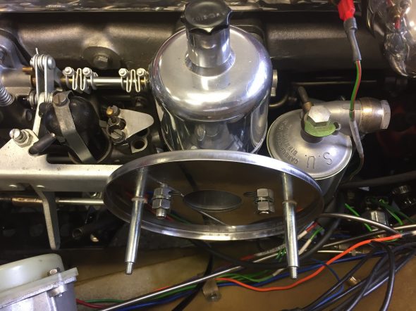
Air Filter Rear Plate Mounted
The K&N oiled filter is then installed followed by the cover plates secured by shake proof washers and acorn nuts on the studs.
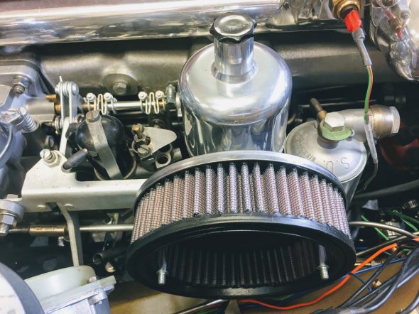
K&N Air Filter Element Installed
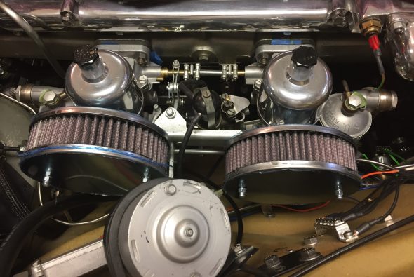
APT K&N Air Cleaners Temporarily Mounted
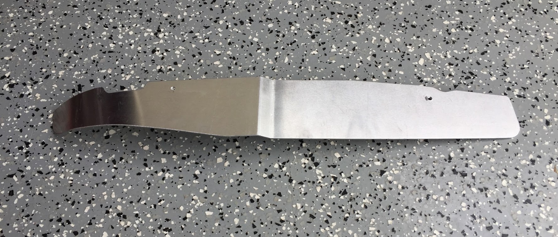
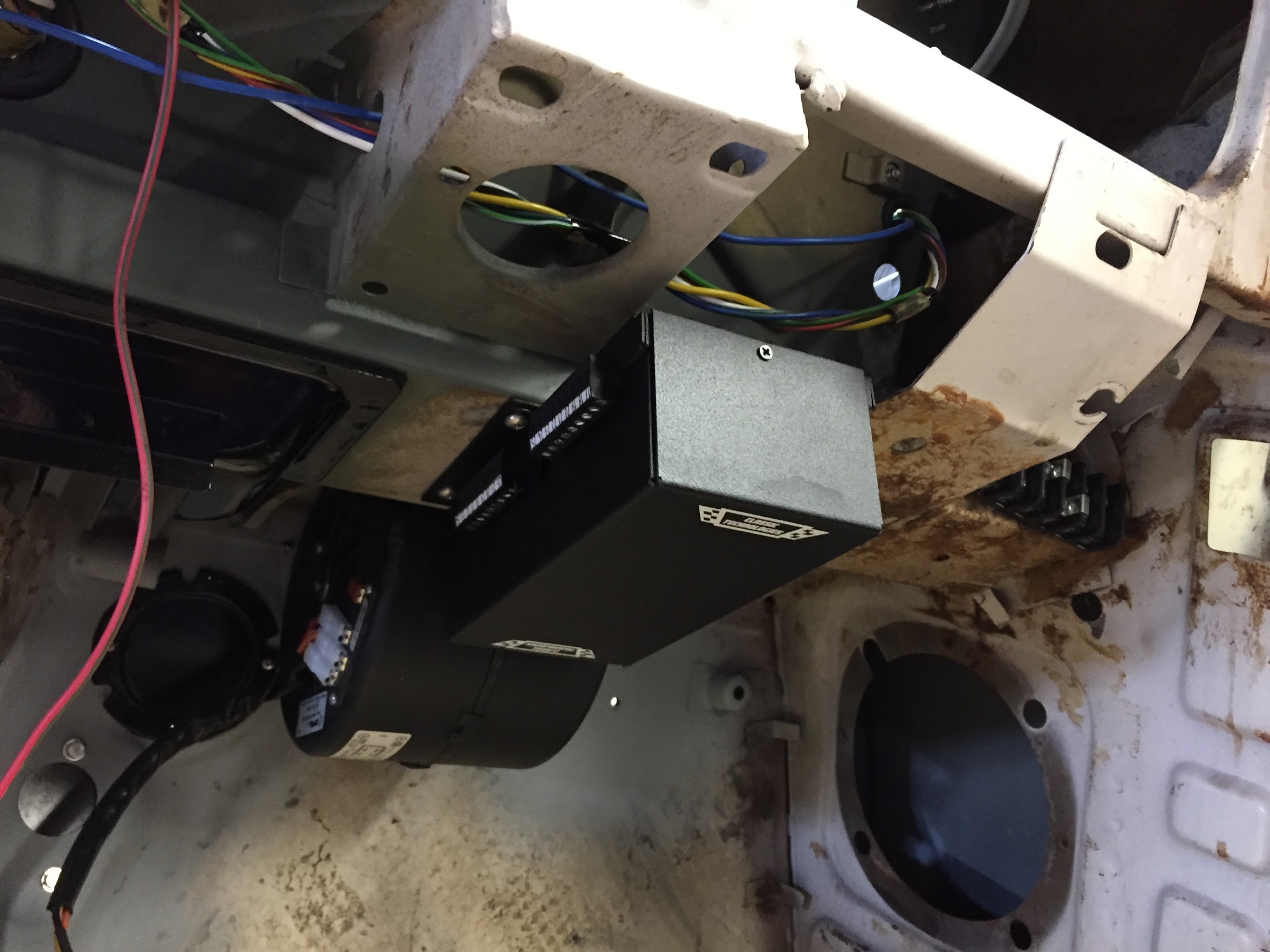
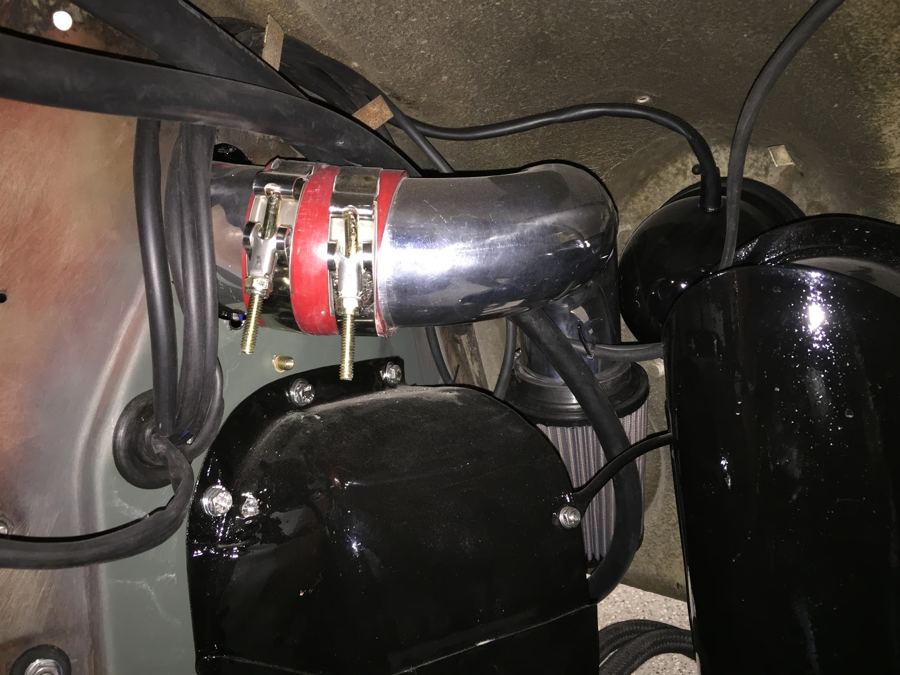
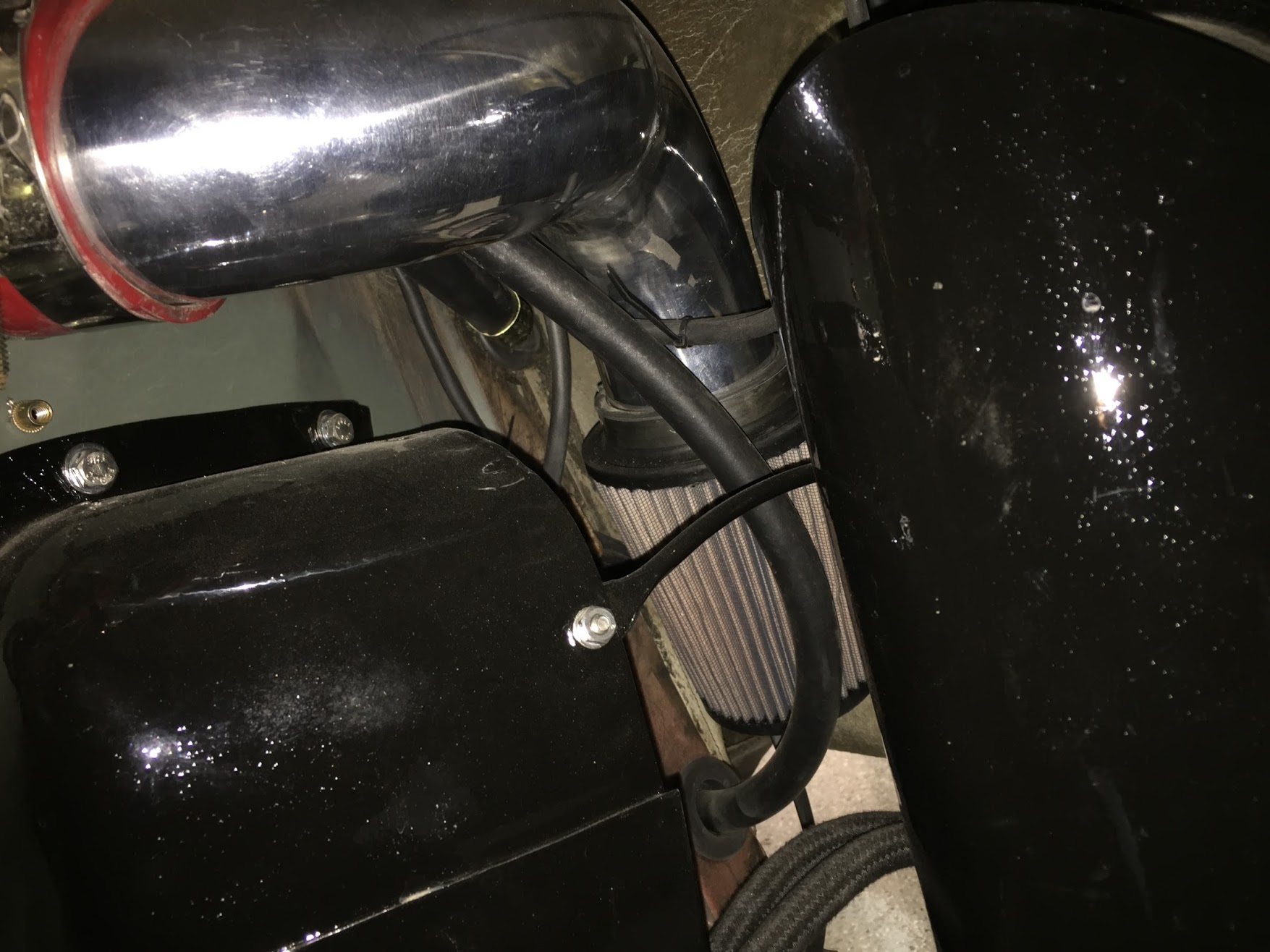
Air Cleaner Update – Cold Air Box
Well, after the time devoted to researching the ideal air cleaner solution and the expense of ordering the K&N offset filters, I became convinced that an air box delivering cool air to the carbs is the way to go. I recently saw several approaches to these “boxes” on some of the Jag Forums, and Mike Gassman of Gassman Automotive convinced me that the cold air delivery system would be a good modification to make to assist with expected heat problems under the bonnet. I anticipate that my air conditioning system will add more heat to an already “hot” situation. Mike has a very talented welder/fabricator on his team, Brandon Tyree, who designed, fabricated and installed the “box” – I am going to call it a “pipe.” I don’t know why “they” call these things “cold air” boxes – they do not deliver cold air, but instead, ambient air from outside the engine bay to the carbs. A “pipe” also has all smooth and rounded surfaces which would seem to promote better air flow than a “box.”
This topic deserves a separate post and it may be found at: https://valvechatter.com/?p=9163