
Radiomobile Radio Housing and Aerial
Radiomobile Aerial
The aerial height on my Mk2 was controlled by a hand crank and cables. The hand crank was located below the steering wheel through the finisher panel. I was going to forgo the use of the aerial since my aerial was broken, but Robert Seligman (also restoring a 64 MK2) and John Stefanik (professional restorer and metal man extraordinaire) reproduced the Radiomobile crank mechanism and replacement aerial masts. Consequently, I am excited to be able to use the mechanism as originally installed! I am indebted to Bob and John for their talent, creativity and persistence.
George Camp sent photos of the correct fitting so that I might try to get my assembly close to the original.

Aerial Mast Fitting
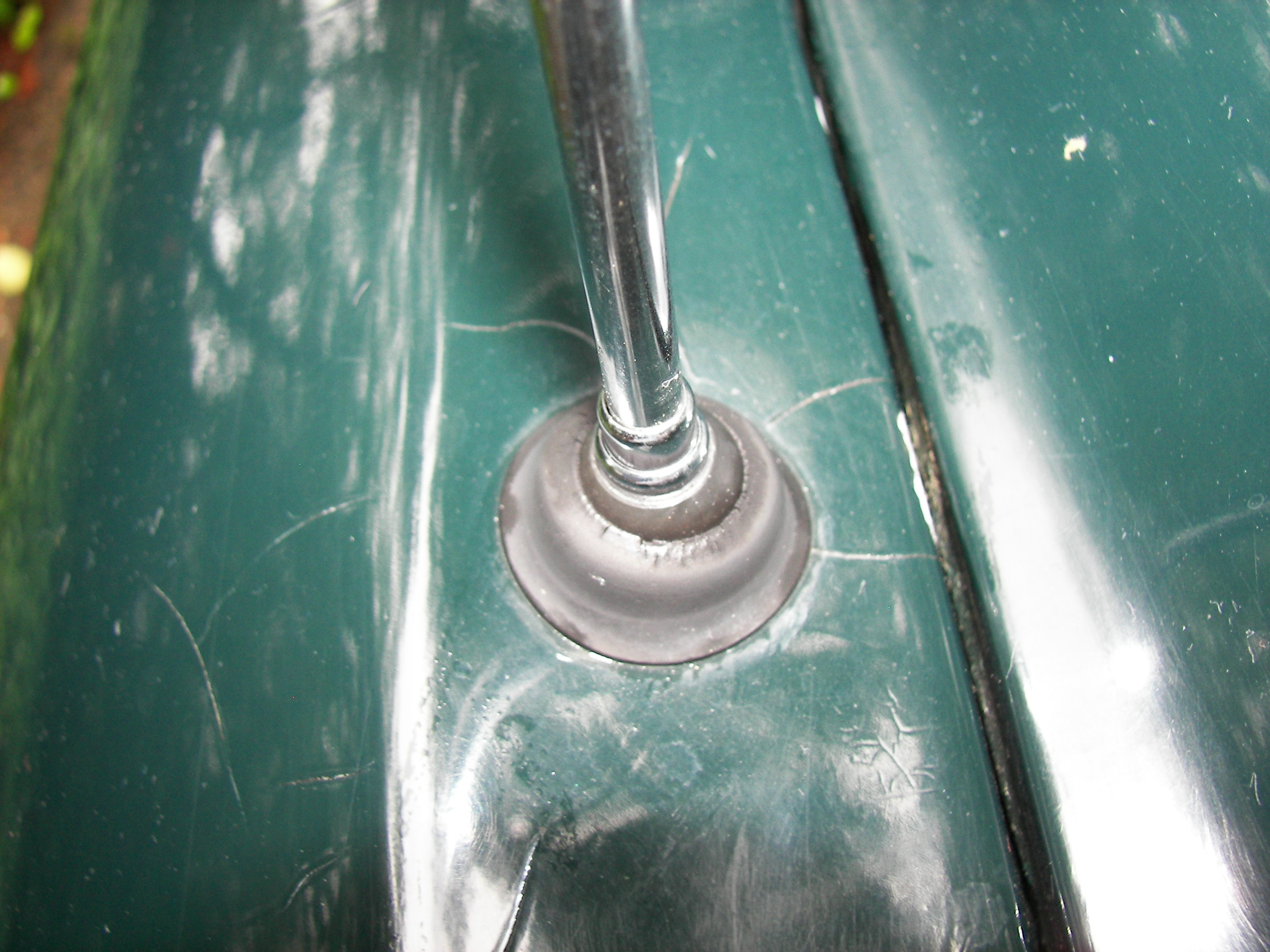
Aerial Mast Fitting
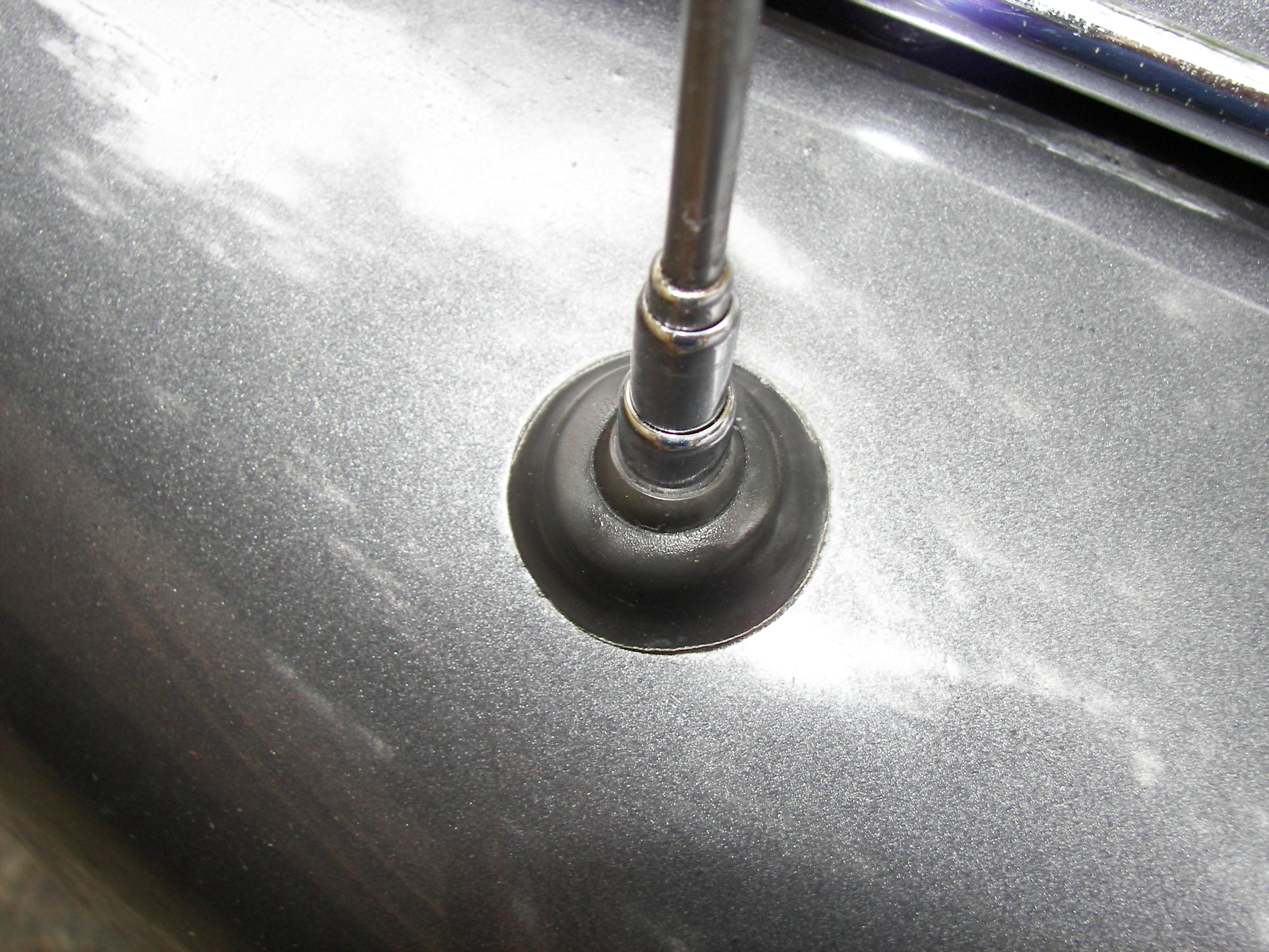
Aerial Mast Fitting
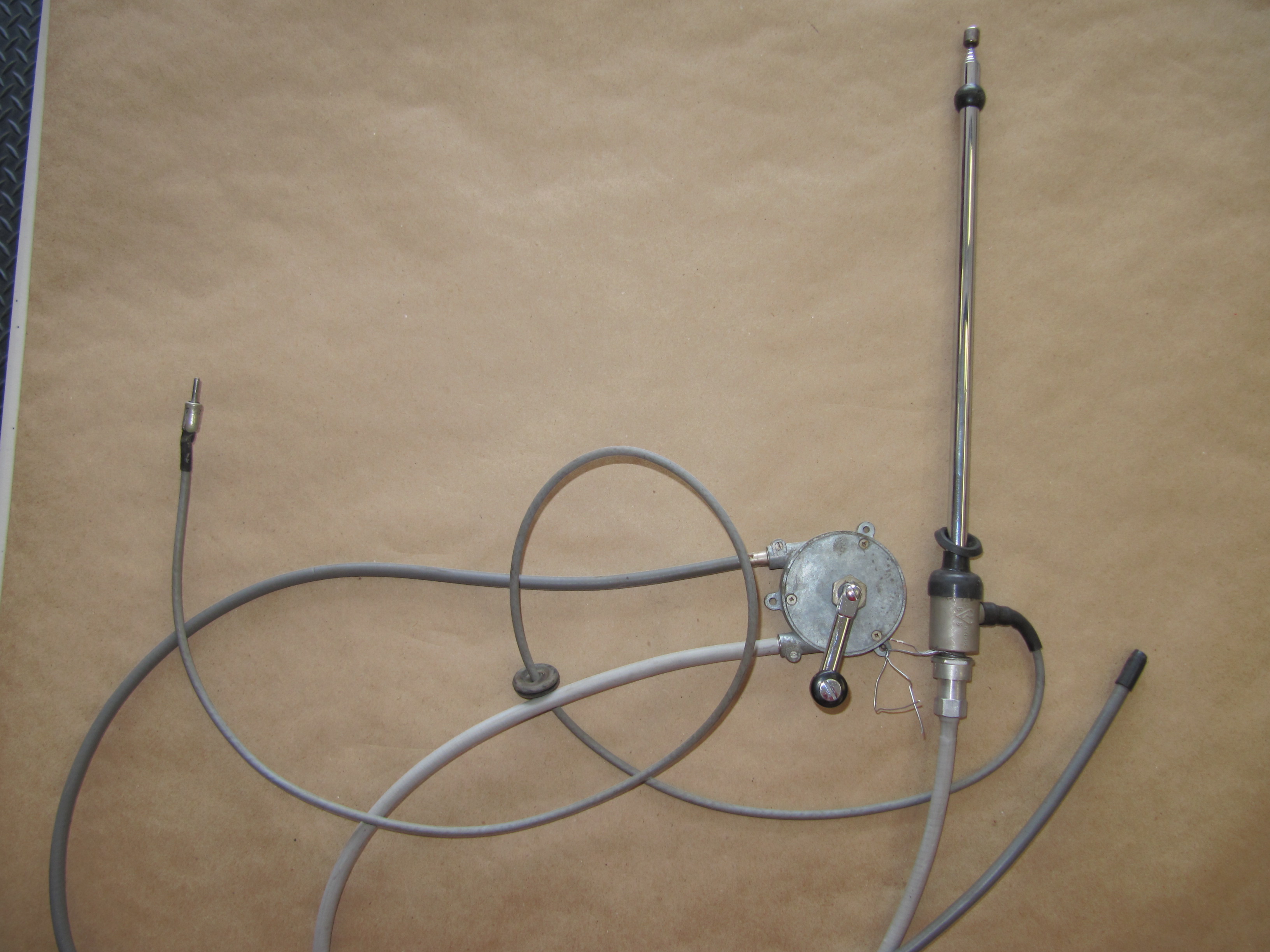
Radiomobile handcrank Aerial
John was able to source new cables and now has my assembly in working condition.
Bob Seligman was somehow able to find a rubber grommet with a five degree offset that will work on the MK2. It is a little smaller than the original, but I am happy to find a grommet that will work!
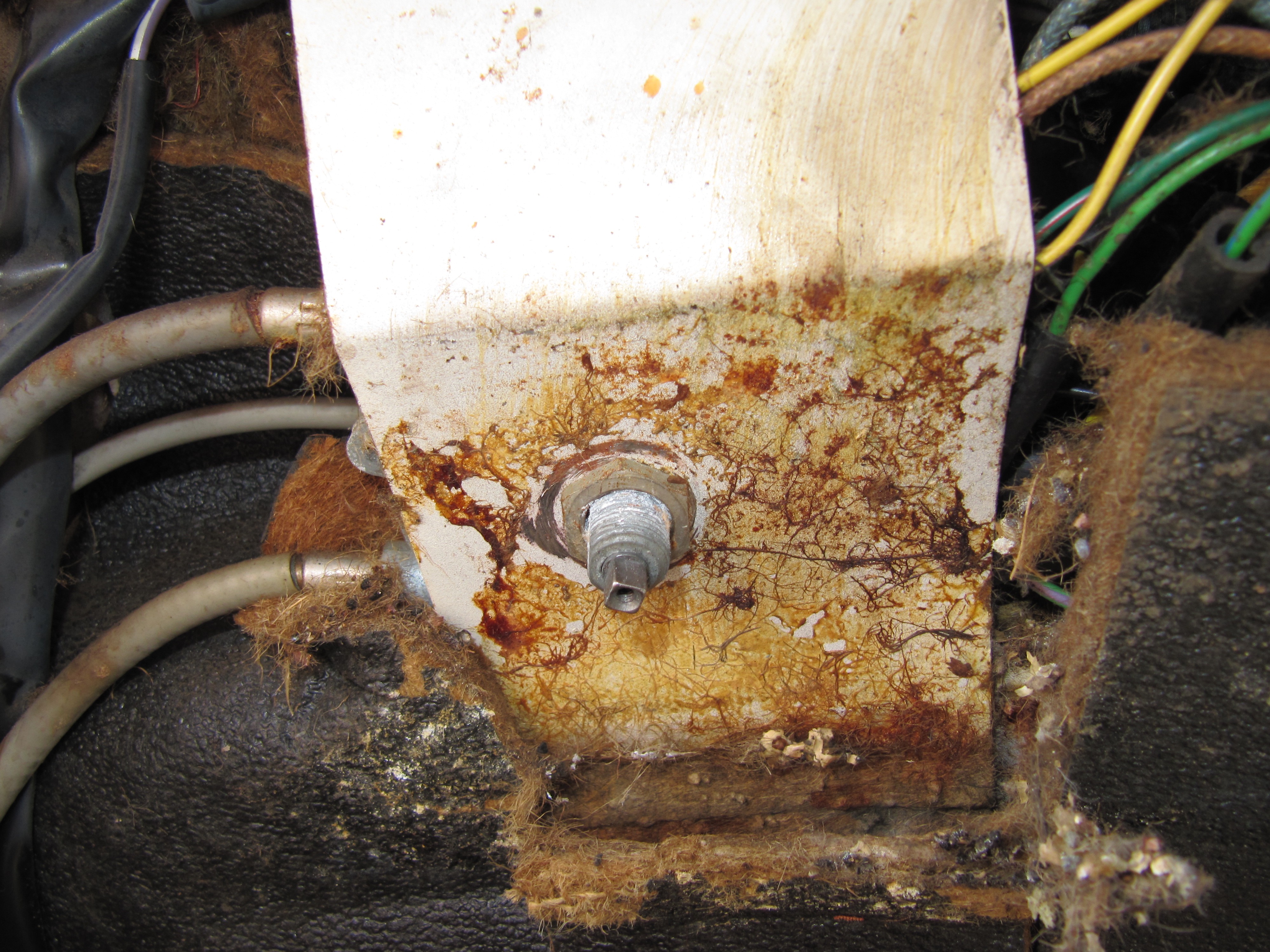
The antenna mast is mounted inside the LH kick panel radio speaker opening. It is a little hard to see, but if one enlarges this image you can see the bracket inside the void between the LH wing and the inner body. The base of the antenna mounts on the bracket and the mast exits out the hole in the body.
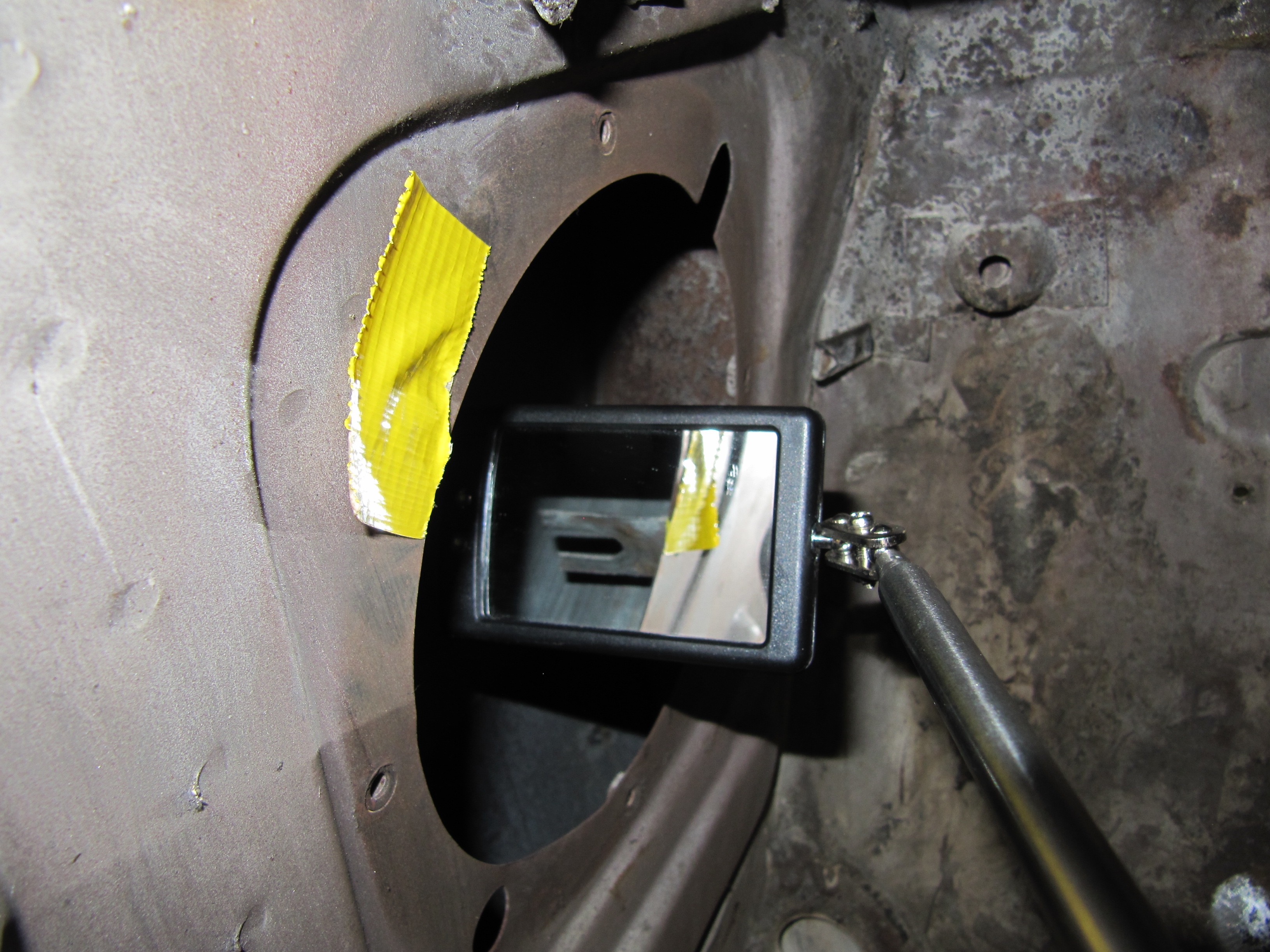
Radiomobile antenna mounting bracket
These are directions for the installation of the radio, aerial and speakers. The directions, presumably prepared for RH drive cars shows that the antenna and the rotating controller are to be located on the RH side of the car. Several MK2 owners have reported that their controller is mounted on the RH side; however, my antenna and controller are located on the LH side of the car. The controller is mounted under and to the left of the steering wheel. This seems like a much more practical location for a LH drive vehicle.
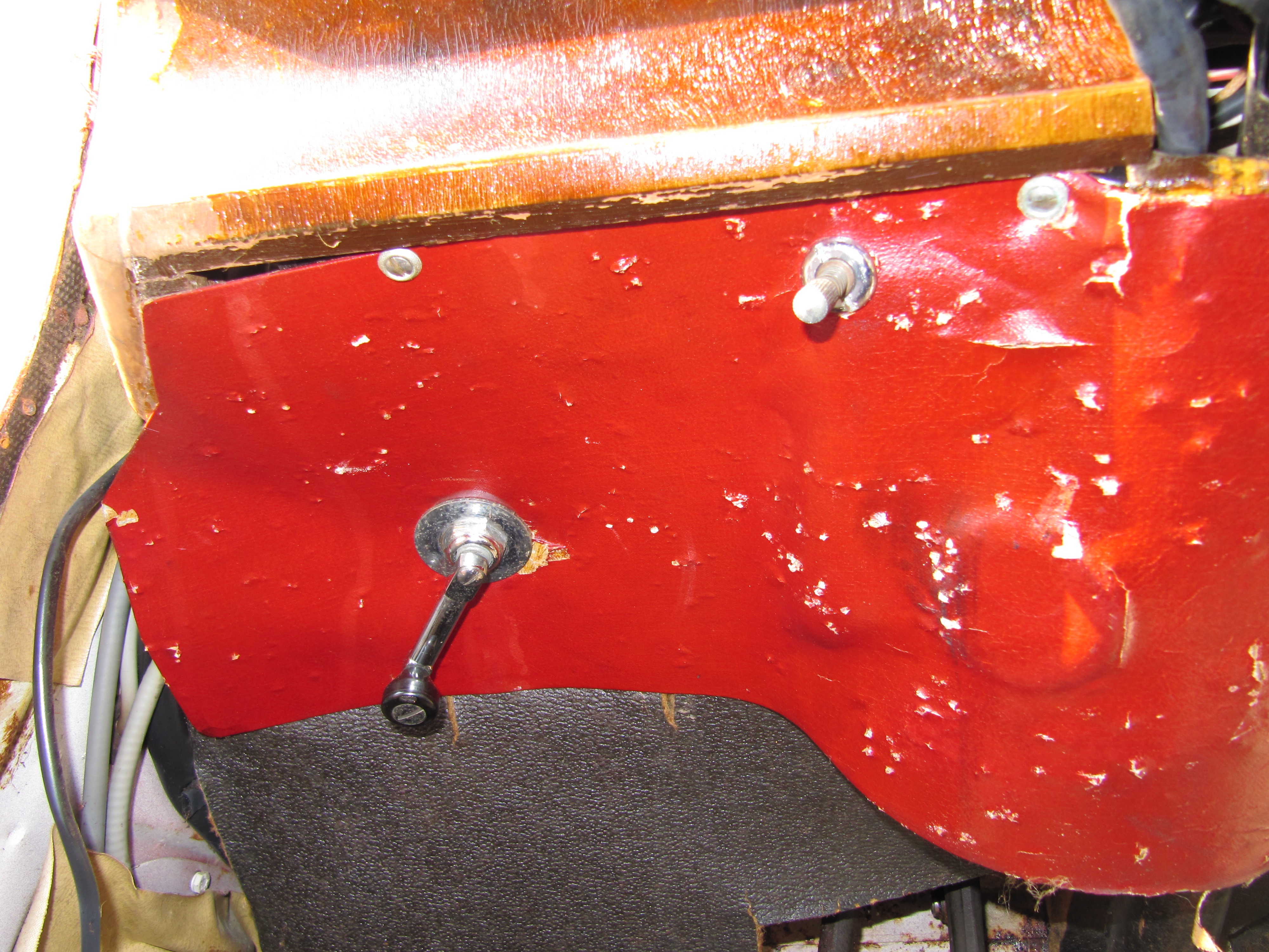
Radiomobile antenna mast rotary controller
Radiomobile antenna mast rotary controller under panel
Radiomobile Installation Instructions
Additional instructions are provided on page 21 in this little book:
Radio Control/Finisher Panel
The Radiomobile radio is housed in the Finisher or Control Panel Above Tunnel. The radio as set up was for positive ground, but apparently there is a switch inside the unit that will permit it to be transformed into a negative ground unit. A set of thirty-nine detailed images are available at this Flickr link:
https://www.flickr.com/photos/valve-chatter/sets/72157632437770125/
The Finisher or Control Panel also includes the lever controls for the “Hot” and “Cold” air settings as well as the “Car” and “Screen” settings.
Front Finisher Panel Assembly Above Gearbox Tunnel with Radio
A single speaker is housed above the radio behind a chrome speaker grille.
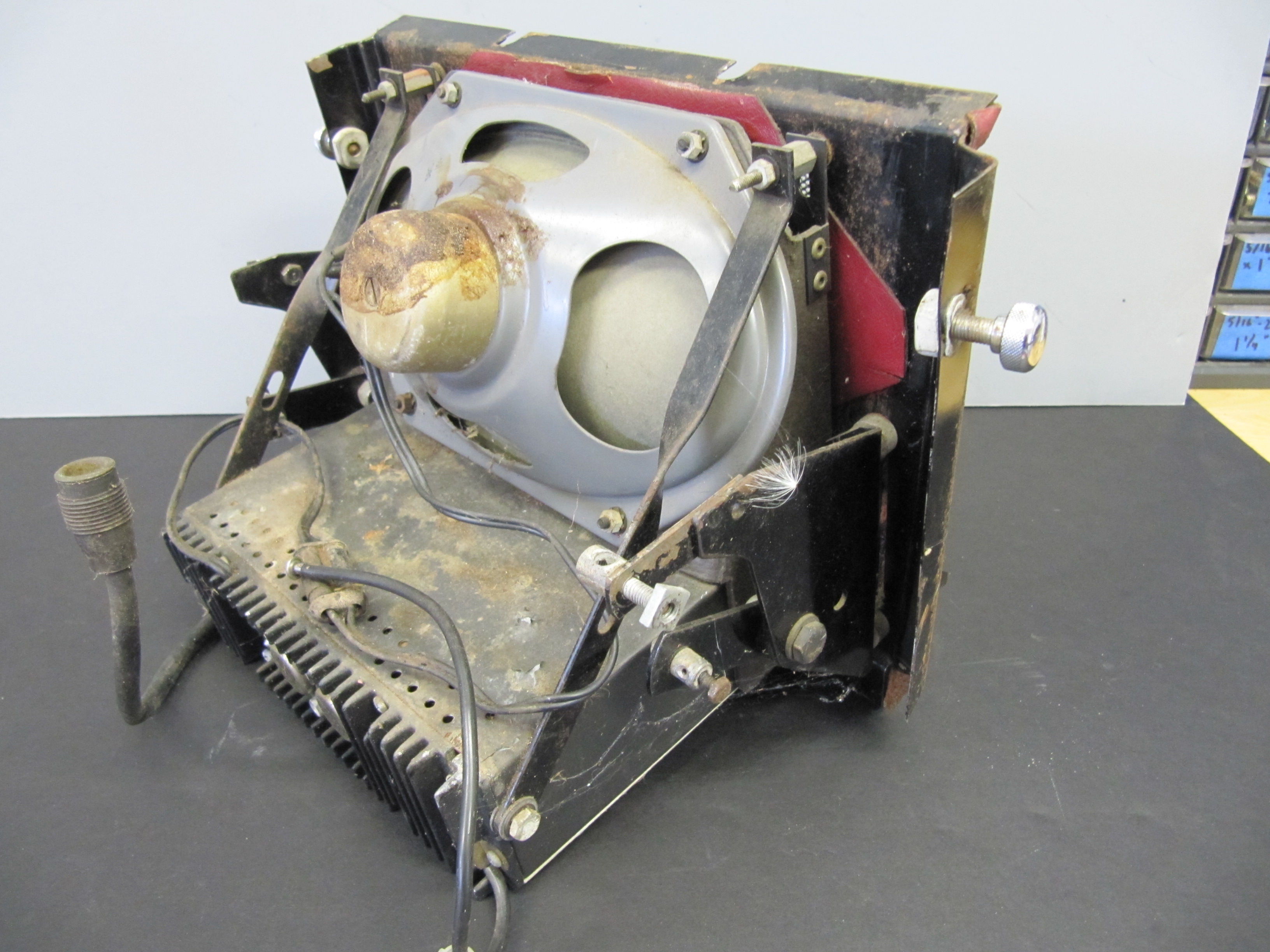
Speaker Mounting Above Radio
Heater Controls Air control levers are located on either side of the radio and are operated by cables from the Heater Box. Additional information about the heater control levers is available under the “Heater” posts.
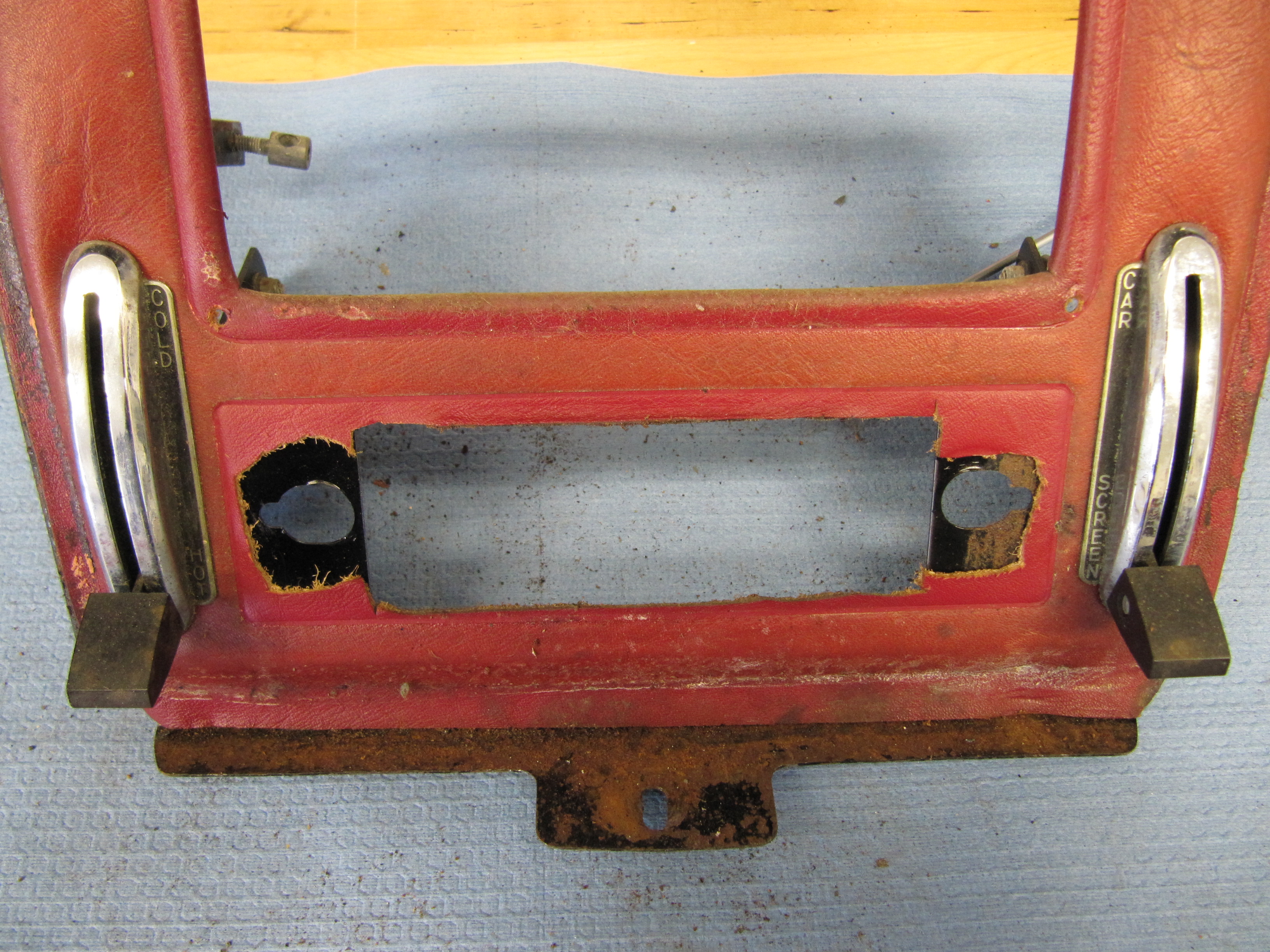
Lever Assemblies for Hot and Cold and Car and Screen Controls
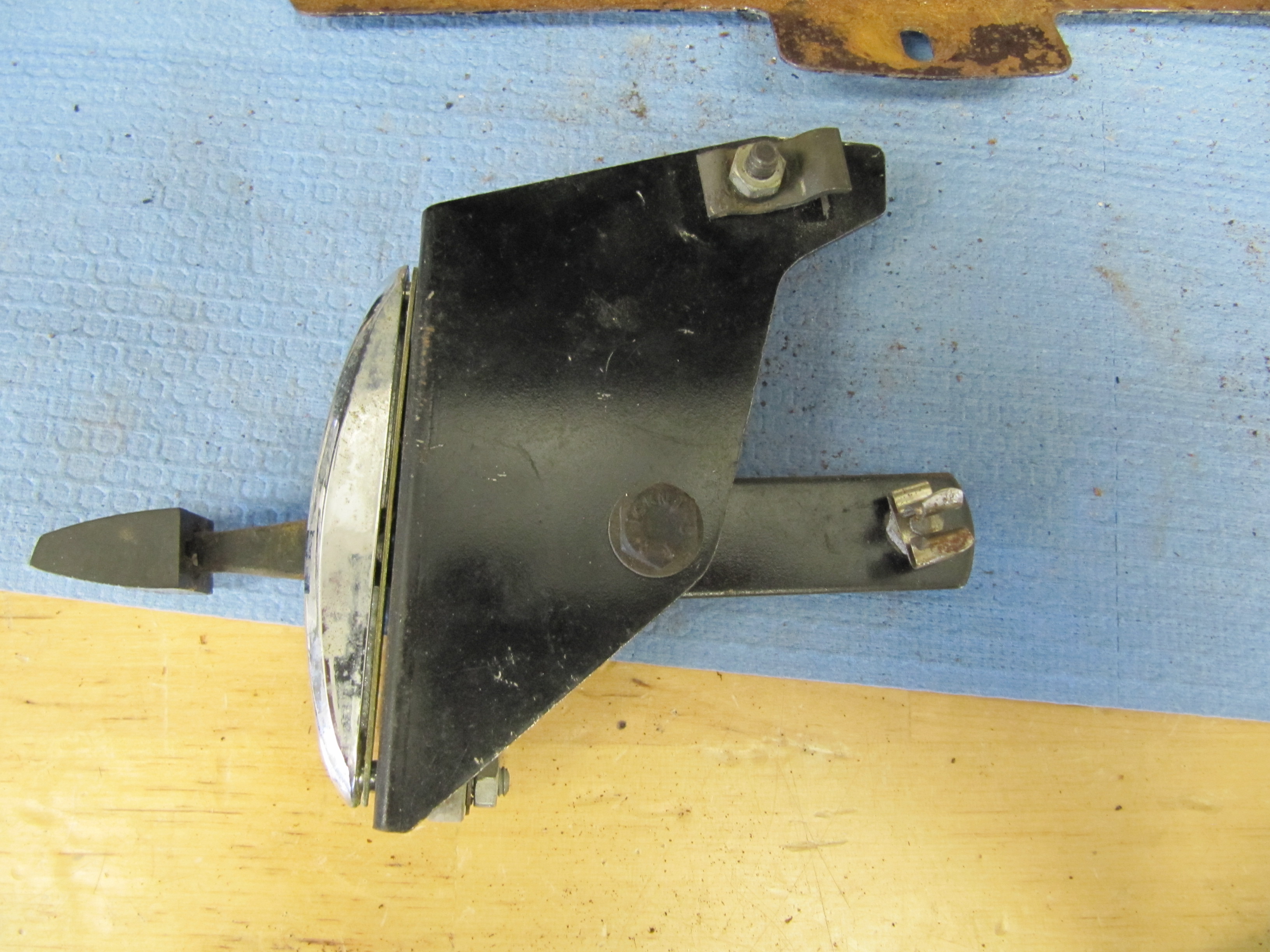
Lever Assembly
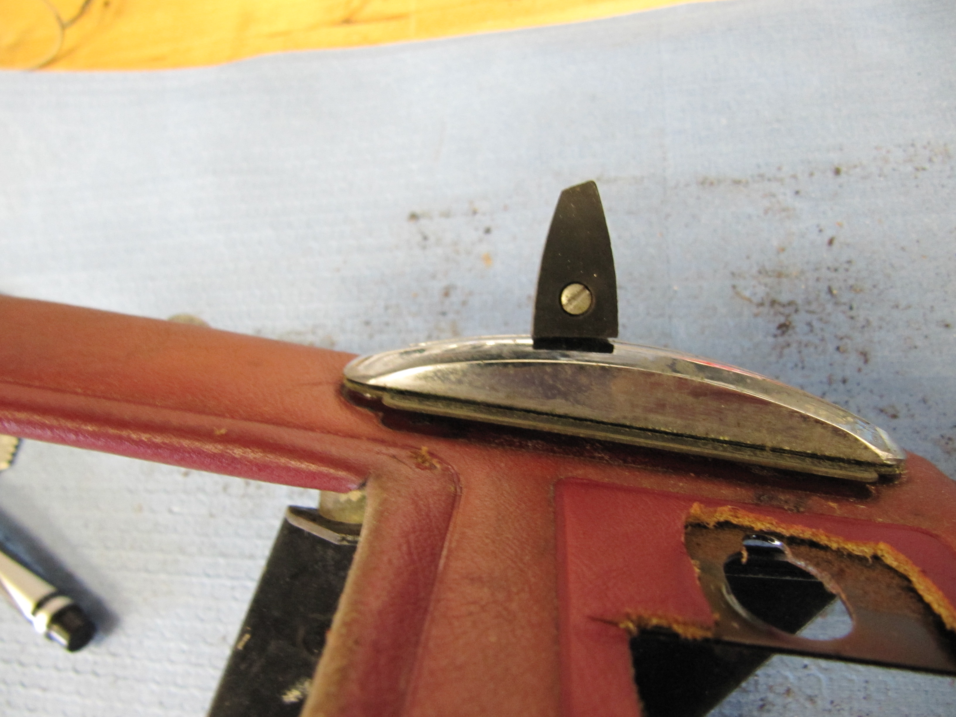
Knob on Heater Control
Lever Assemblies
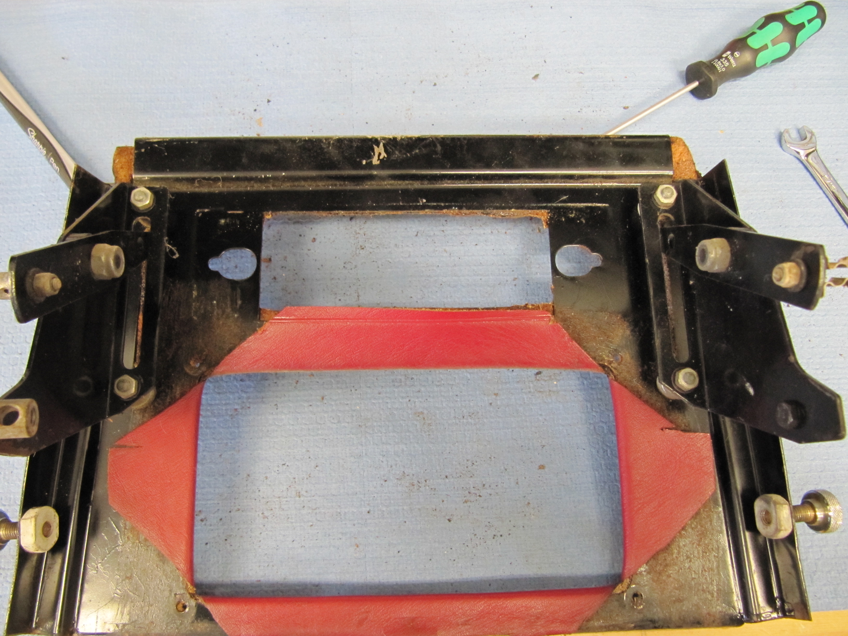
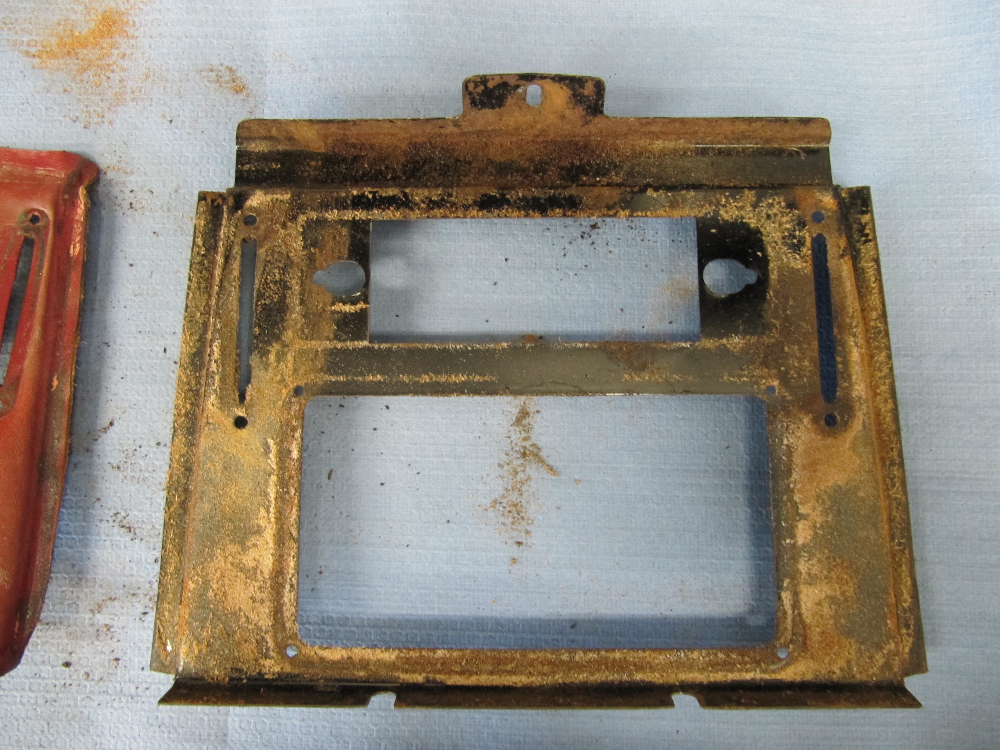
The Panel is covered in vinyl which was removed and saved to use as a pattern later. The panel was then media blasted and set aside. No decisions have been made as of yet regarding the sound/navigation system that will be installed, but it is likely to require modifications to the sheet metal of the panel.
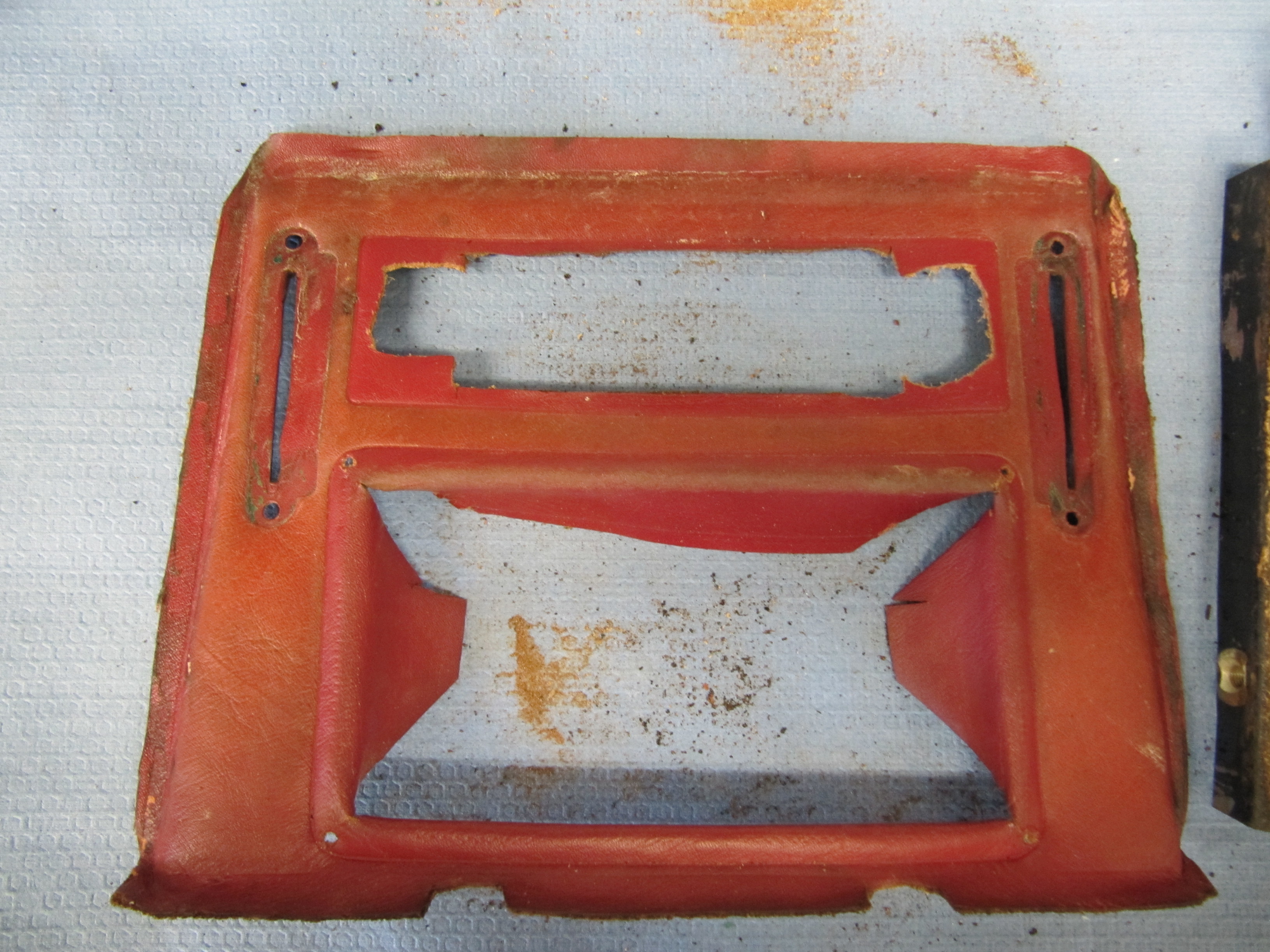
Panel Vinyl
Vinyl Removed

Finisher Panel Cleaned
Radio Control Unit Support Brackets Two support brackets that connect the top of the control panel to the radio unit were cleaned, media blasted, primed and painted.
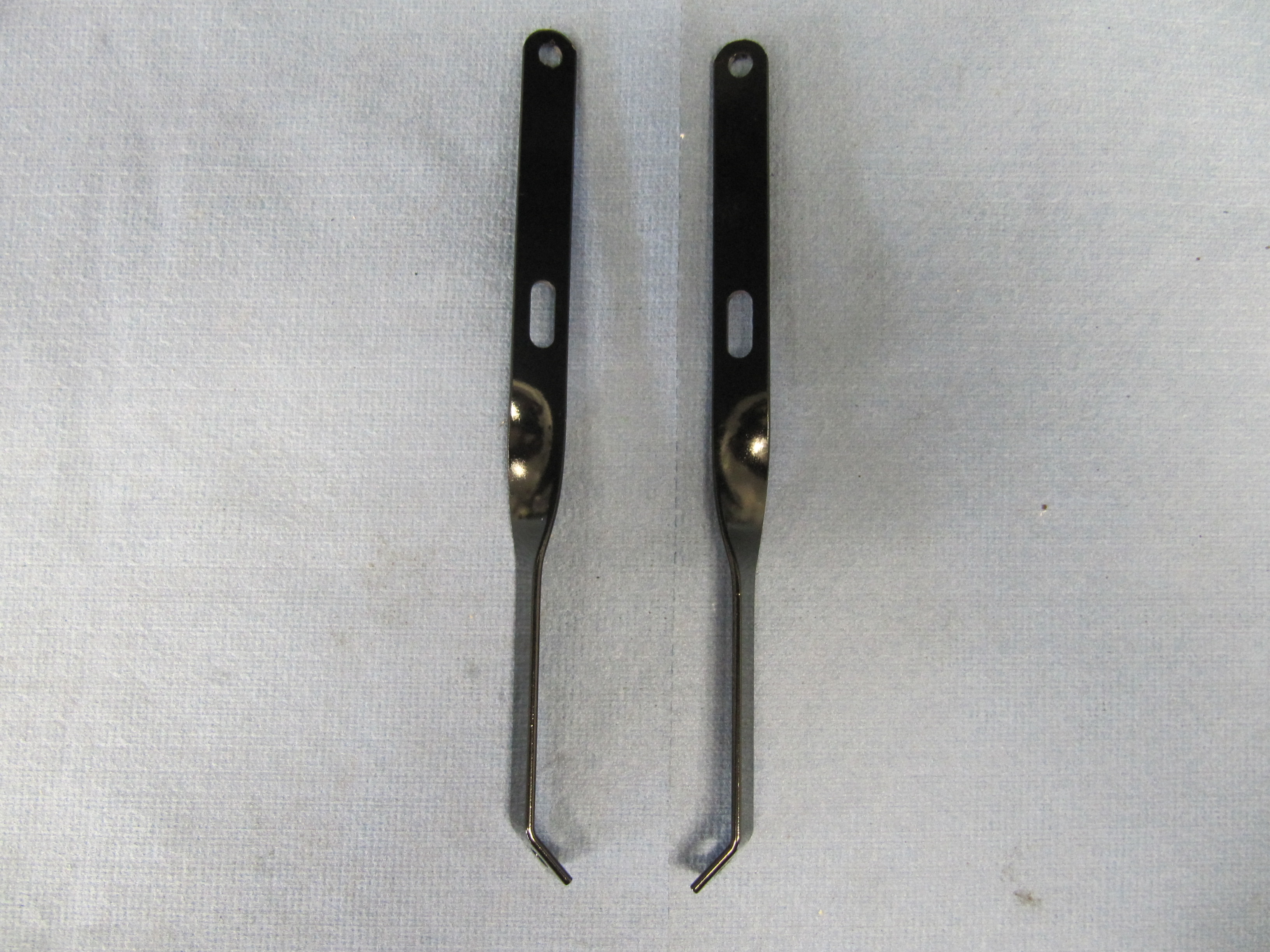
Radio Control Unit Support Brackets
The Radiomobile Radio
My 1964 MK2 had a Radiomobile radio in it when I purchased it. Apparently it was installed by the dealer at the time of delivery but I cannot be sure. I do have the original Smiths Radiomobile Car Operating Instructions and the original Smiths Radiomobile Guarantee Registration Card. While the card has the radio model number on it the card was never completed and sent back to S. Smith and Sons (Radiomobile) Ltd.
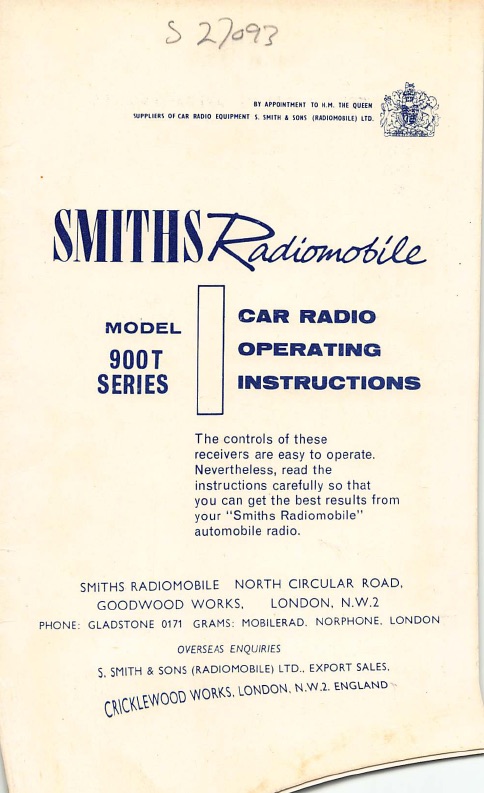
Smiths Radiomobile Car Radio Operating Instructions
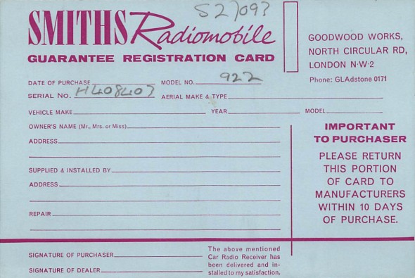
Smiths Radiomobile Guarantee Registration Card
My radio did not function and it was also positive ground. I wanted to upgrade the sound system in the car, but wanted to try to retain the original look of the original radio. After some internet searching I came upon Retro Radio Restoration owned and operated by Mike and Chris Frenchek in Elizabethtown, PA. http://www.retroradio.biz/index.html
Mike will restore you original unit or he will convert your radio to add power and features while retaining the look and many of the functions of the original radio. I chose to convert my Radiomobile. The process takes about six months so you cannot do this if you are in a hurry!
In the conversion process the original electronics were replaced with a new high power digital stereo receiver designed to work with the original mechanical tuner and controls. Switching between AM and FM bands is accomplished by quickly turning the radio off and then back on again. Pushbuttons can be set for AM and FM stations using the same method that was used originally. Four BTL amplifiers capable of delivering 45 watts RMS each provide 180 watts RMS maximum output power. (14.4 volts, 4 ohm load, 1kHz.
I chose to have my unit configured for four speakers and all radios are equipped with RCA inputs and the necessary control lines to plug into a CD player or a satellite radio. I also added optional blue tooth, a USB port, and line outs for a subwoofer and an additional external amplifier. I have yet to determine if I will use a subwoofer or and additional amplifier, but I am ready if I choose to do so.
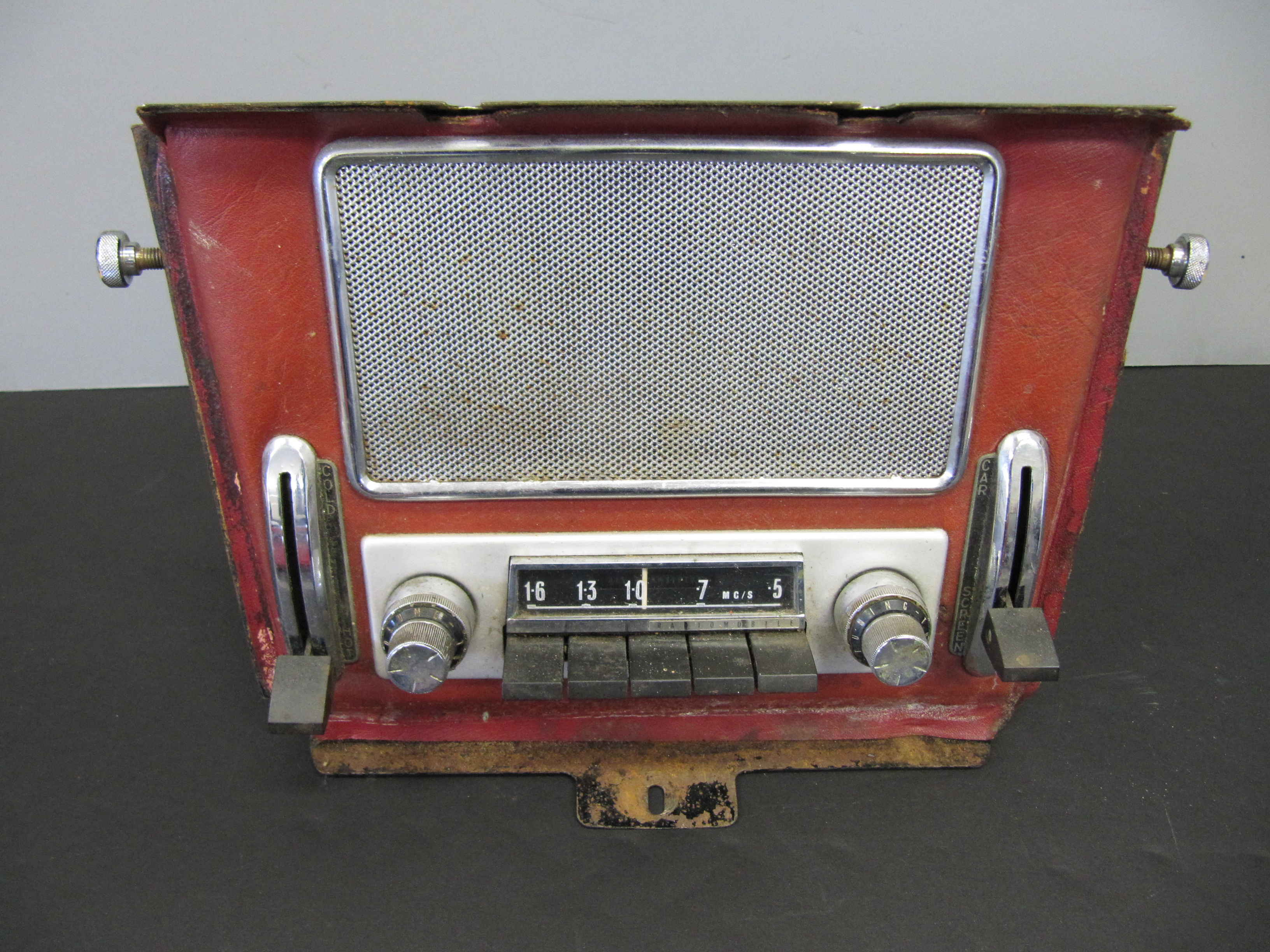
I just received my radio from Mike and my first impression is very positive. He tested the unit and said that it sounded great, but I have not yet tested it myself. I still need to determine what speakers I will use. I polished the knobs and push buttons and it all looks quite good. I have some scaling on the chrome casing of the radio and I may have the face rechromed. An aluminum face plate is used to mount the radio to the finisher panel and that is a shame because the chrome face of the radio actually looks better than the aluminum face plate!
These are a few images of the radio as it was received from Mike. It will be put away for now but I look forward to coming back to it a little later in the restoration project.

Radiomobile Conversion with Mounting faceplate
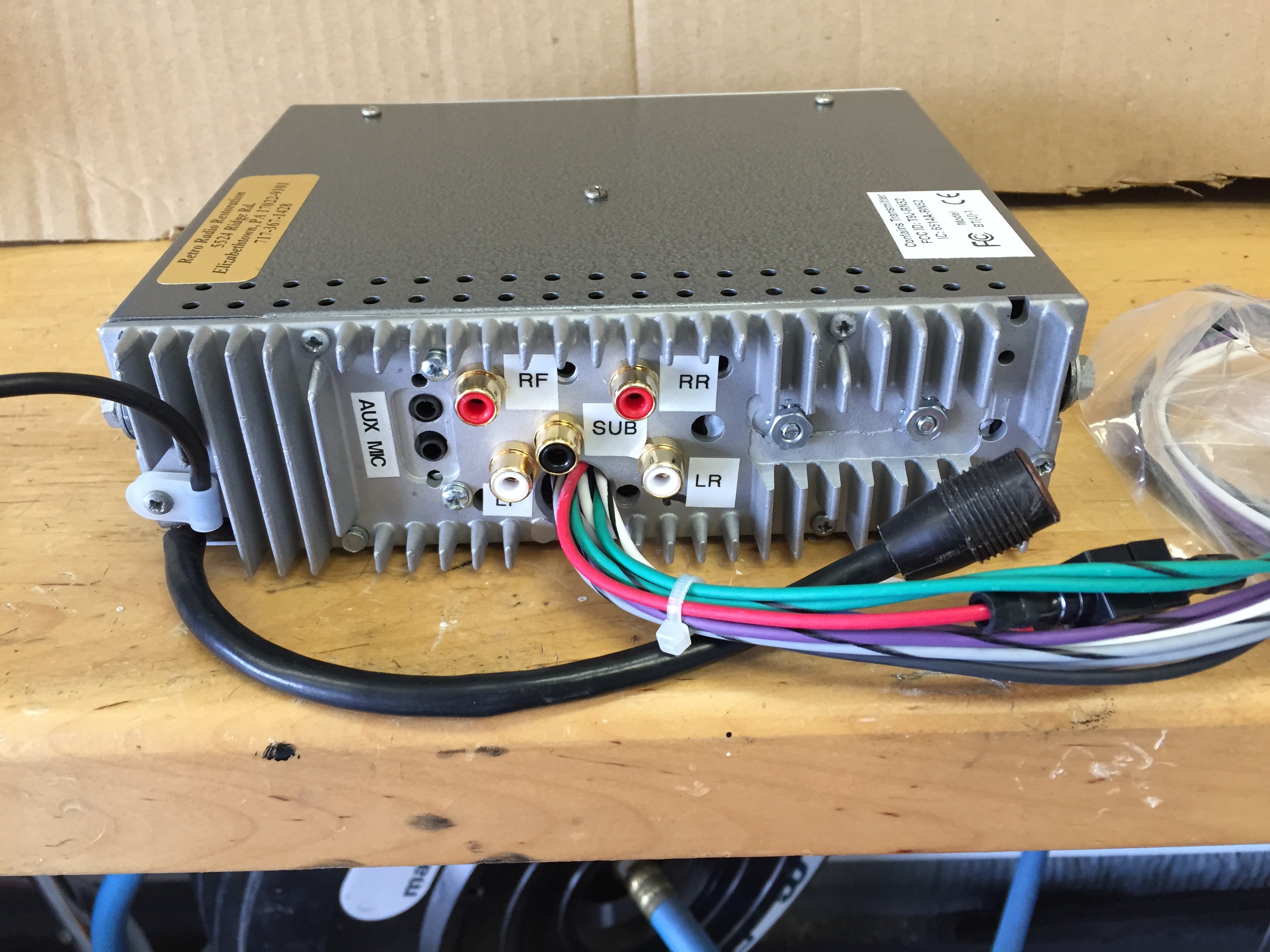
Radiomobile Conversion with new ports
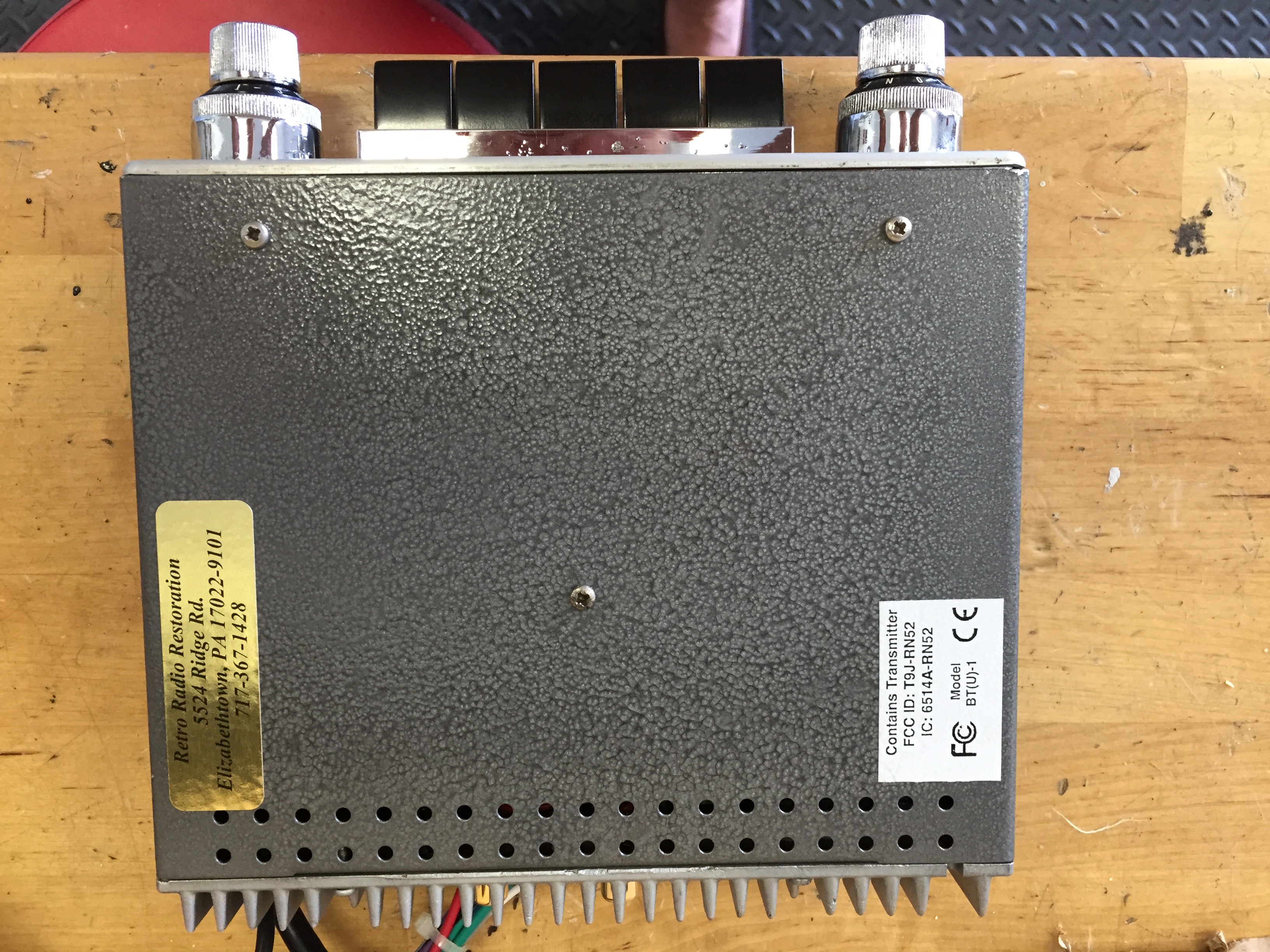
Radiomobile Conversion Casing Blasted and Painted
These are the directions for the operation of the converted radio:
Rose Radiomobile Conversion Directions
Rose Radiomobile Bluetooth USB Instructions