The Bugeye – 1959 AN5

My name is John Rose and I am the current owner of AN5L11257, engine number 9CUH10910, a 1959 Austin Healey Sprite, popularly known as a “Bugeye” in the States or “Frogeye” if you are from across the pond.

This web site is dedicated to documenting the history of my car, the modifications that have been made to it, and the fun I have had with it.

My Dad, Linwood Rose, my younger brother, Scott, and I attended the 1998 Sprite Bash in Carlisle, PA with the idea of finding a Bugeye to purchase as my first car. Of course, I wasn’t old enough to drive yet, but this was to be a “project” car that would require some work prior to putting it on the road. We looked at a few cars that were for sale, but didn’t make any offers in Carlisle.

Previous Ownership

Later that summer, we were attending the British Car Days Show held in July at Bowie, Maryland on June 28, 1998. Tom Delaney from College Park, MD attended the Show and was walking around the show grounds with a sign taped to the back of his T shirt he was wearing that stated, “1959 Bugeye for sale, enquire within.” I struck up a conversation with Mr. Delaney and we agreed to stop and see his car when we returned from vacation at the end of the week.

Negotiating with Tom Delaney, British Car Day, Bowie, MD June 28, 1998

On July 2, 1998, after a test drive and some negotiating, I was the proud owner and we were driving MY Bugeye home from Maryland to Harrisonburg, VA.

Mr. Delaney did have some records that he passed along to me with the car. These records provided some insight into previous ownership of my Bugeye. I am not sure when Mr.Delaney purchased AN5L11257, but I do have a receipt for parts indicating he was the owner in February 1983.

Curiously, before Mr. Delaney was the custodian of my Bugeye, it was apparently owned by Captain Charles A. Rose of Gaithersburg, MD. I say “curiously,” because my uncle’s name is Charles Rose, and he lives in Maryland, but they are not one and the same.

Captain  Rose purchased my Bugeye in Tennessee according to Tennessee DMV records in September, 1979 from Dean Trathen from Nashville, TN. Mr. Trathen apparently owned the car for only a brief period having purchased it himself in March of 1979 from William L. Easterling from Brentwood, TN. Records show that Mr.Easterling bought the car in September of 1978.

Unfortunately, I don’t have records or any knowledge of ownership of my Bugeye from 1959 to 1978.

Bugeye Blog, 1998 – 2021

My Bugeye Blog chronicles the life and times of AN5L11257 while in my care. I didn’t keep good records at first, so details are a little sketchy until 2000. As the reader of my Bugeye Blog will observe, we have made many “personalizations” to my Bugeye. I have concentrated on making my car fun to drive by increasing performance and handling. The Bugeye Blog runs through 2021.

The Total Restoration of AN511257 Beginning in August 2022

As with most things that age, my Bugeye is now a little “tired” and needs some major attention. The body and interior in particular need to be completely reworked. So, in early August 2022 I took the Bugeye to my father’s home where he plans to undertake a complete restoration of the car. 

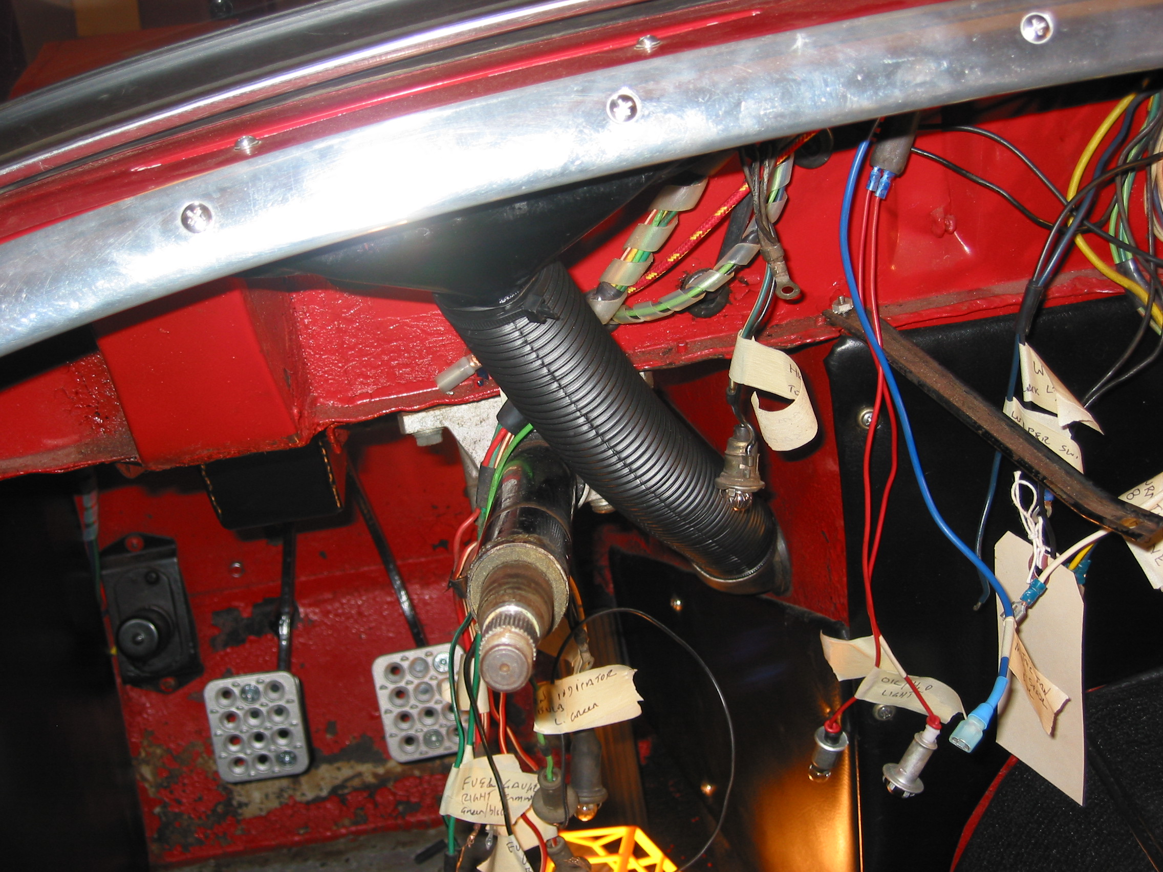
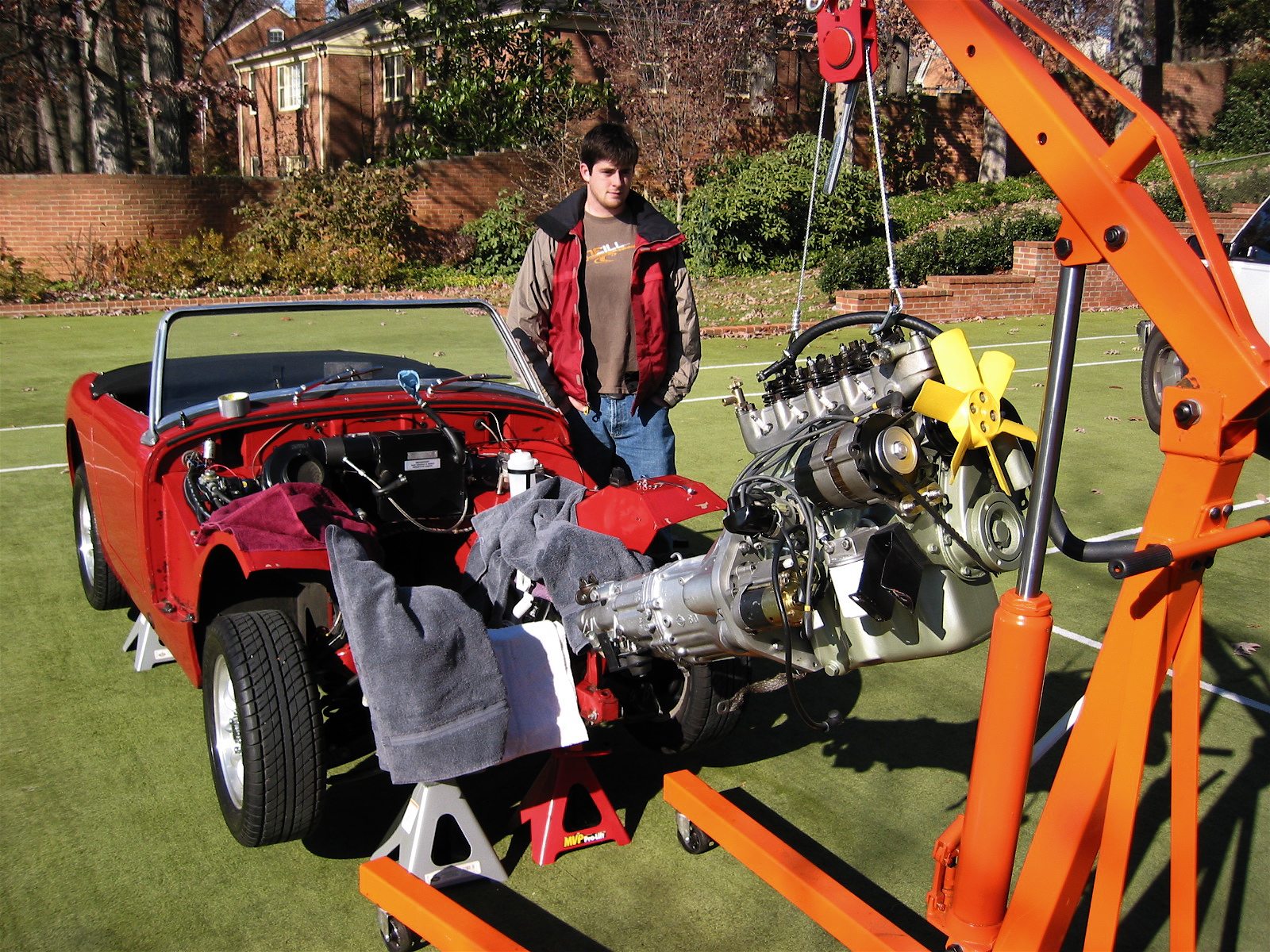
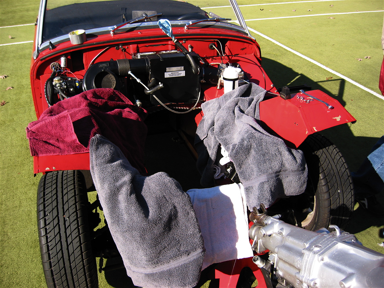
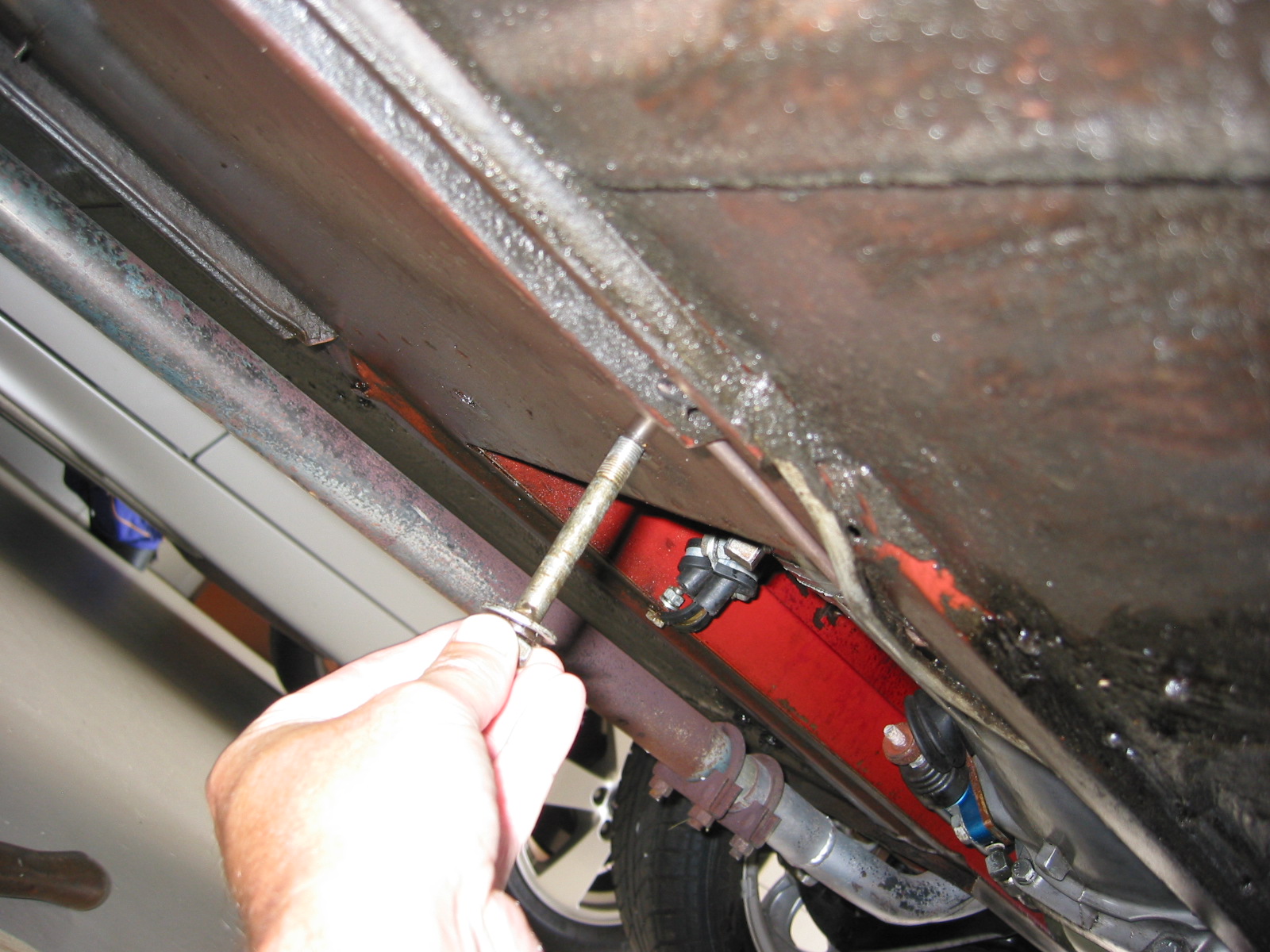
The plan will be to totally restore/replace all of the major systems of the car such as the rear suspension and axle, the front suspension and steering, the drivetrain, brakes, heating and cooling, the interior, and the body. As each system is attended to it will be reinstalled in the car to ensure fit and proper function. After all of the systems have been restored/replaced/upgraded the car will be dismantled for bodywork and paint. This process may take a little longer than otherwise, but it will ensure that everything fits and operates perfectly before the car is in fresh paint.

Each step along the way will be documented on this website and will include narrative, photographs, and videos. The posts, or entries, will be separated into two sections. The first will be the Restoration Phase and the the second will be the Assembly Phase. We will also create a category with posts for modifications/personalizations organized by topics such as “fuel” or “steering.”

I hope you enjoy the ride!

John Rose


Storing the Original 948cc Motor

Engine & GearboxMy Dad built a new house and he is “downsizing,” so some car parts are needing to go to a storage unit. When we upgraded to a 1275 motor and Datsun 5-speed gearbox, we kept the original 948cc. I will never plan to go back to the 948, but if the car is ever sold it will be nice to have the original numbers-matching engine. Apparently, the original gearbox was replaced with the ribcase box somewhere in its history..He has a climate controlled unit, but the motor and gearbox needed to be put away properly so he built a nice plywood box for the storage unit.

Fluids were drained, and Marvel Mystery Oil squirted into each cylinder. Desiccant plugs were purchased from Moss Motors and installed in place of the Champions. Holes were plugged and the top of the box was screwed in place. Who knows when this motor and gearbox will see the light of day again!

Desiccant Plugs

Desiccant Plugs

Backplate Brace

Backplate Brace

Tucked in for the Night

Tucked in for the Night

Engine Storage Box

Engine Storage Box

New Tires & Fuel Pump

I am a little late recording this, but in September 2010 the Bugeye’s shoes were replaced. While the tread on the Wynstar tires looked just fine, they were over eight years old, so for safety sake it was time to replace them. The same tire was no longer available, so the Bugeye now has some P185/60R13 80 H Sumit HTR 200. These tires are not the same low profile as the Wynstars, but the ride is superior and the grip firmer than before. Details are available on the maintenance page of this site.

The Sprite was neglected a bit over this winter, so when a warm day came round near the end of February, it was time to start her up and give her a good run. Alas, no joy! Either the SU fuel pump was not sucking fuel or there was a clog in the line. After a few diagnostics, it became clear the fuel pump was the culprit. A negative ground electronic SU was ordered from Moss Motors and installed. While messing with the pump, it seemed the ideal time to switch out the old rubber fuel hose for a new hose that is no susceptible to deterioration from ethanol. That done, the Bugeye is now happy and running once again!

Fuel Pump Installed

Fuel Pump Installed

Fuel Pump Installed

Fuel Pump Installed

SU Fuel Pump Part Number

SU Fuel Pump Part Number

2008 Encounter

Ready to AutocrossThe Austin-Healey Sports and Touring Club – A Car Club for Healey, Austin-Healey, and Austin-Healey Sprite Owners and Enthusiasts with regions in New York, Pennsylvania, Delaware and New Jersey always puts on a great annual event referred to as “Encounter.” The event is held in August of each year.  A judged Concours, popular vote car show, a rallye, tech sessions, a gymkhana, funkhana, valve cover races and a flea market are just a few of the usual events. Click the image to the left to view a slide show of the 2008 event held in Carlisle, PA.

My dad and I attended this year. I drove the Bugeye and he drove the “Bloody Beast,” his recently restored 1960 Austin Healey 3000 BT7, from Harrisonburg. We couldn’t attend when the event got started, but we headed up to Carlisle at about 5:30 am Friday morning, attended activities on Friday and Saturday and headed home Sunday morning. We enjoyed the great weather, and had a wonderful time. I had fun at Del Border’s gymkhana course and the “Bloody Beast” took home first place in the MK I category for the popular car show.

Just Arriving

Just Arriving

Ready To Run

Ready To Run

This is a little video of one of my Gymkhana exploits. I missed a gate, but what the heck. I had a lot of fun and that is what it is all about.

The Hotel Carlisle also hosted the owners of a number of modified trucks the weekend of Encounter, as they were having a show of their own at the Carlisle Fair Grounds. This photo shows one “Encounter” between a Healey 100 and one of the trucks.

Monster Truck

Monster Truck

The famous female race car driver, Janet Guthrie, was the featured speaker of Encounter 2008. One of the topics of her remarks was the Sebring Sprite. This is a photo of one of those Sebring Sprites.

Guthrie Sprite

Guthrie Sprite


A New (And Proper) Master Cylinder

Although I had converted the front drum brakes to disc brakes not long after purchasing the Bugeye, I had not been able to find the proper 3/4” piston version that would have been used on the 1098 cars. My dad was able to source one from California during the previous winter, and in early August he installed it. He ordered the new master cylinder from Gerard Chateauvieux at Gerard’s Garage http://www.gerardsgarage.com Both the clutch and the brake master bores are 3/4″. The push rods are also shorter than the originals. More information is available from theses two pdf files:

Disc Brake Upgrade

BrakeCylinder.com– Midget Sprite Spridget Master Cylinders Disc Brake Upgrade

After bleeding the brakes and clutch we did end up with improved brake pedal feel and stopping power. He removed the entire pedal box, installed the new master and then re-installed the pedal box.

Master Cylinder

Master Cylinder

2006 Gettysburg Car Show

The regional MG club held a popular show (no judging – just display) in Gettysburg, PA. Tyler, Scott, Dad and I attended. I drove to Gettysburg with Tyler navigating. It took us about 2 hours and 40 minutes. The show was held at a shopping mall but they had a great display area set up like a Main Street. It was a short show, 9:30 – 1:30 but we had a good time and saw some nice cars. Three Bugeyes were in attendance and approximately a dozen big healeys from the Capital Area Healey Club.

Grandson with Bugeye in Gettysburg

Grandson with Bugeye in Gettysburg

Gas Struts

Gas Struts

Gas Struts

Gas Struts

Gas Struts

Gas Struts

A Functioning Horn

The Horns

The horn had not worked in the Bugeye since we bought it – not very safe since the bugeye is one of the smallest things on the road. It was time to fix it. The horn itself when tested sounded very weak so I ordered a Hella twin tone horn kit. It came with mounting brackets and a relay for the price of $23.00!

Hella twin note horns

Hella Twin Note Horns

Horn wiring diagram

Horn Wiring Diagram

My horn button is a little different from the original since I have a Moto-Lita wheel, but I ordered a new push pin for it – the 948 Bugeye variety. The pin needs to go into the wheel with the plastic end toward the dash so that the pin is insulated from the body of the aluminum wheel hub. Then the brass sprung pick up on the back of the horn button needs to line up with the pin. The entire assembly then pushes into the wheel hub. A brown wire from the brass contact ring on the dash cone runs to the horn relay.

Horn Button Contact

Horn Button Contact

Steering Hub and Push Pin

Steering Hub and Push Pin

I decided to mount both of the horns on the right front lower side of the frame. That way it was not necessary to run wiring across the frame below the radiator. On one horn I used the original mounting bracket, and on the other I used the supplied brackets and drilled two holes into the fresh air hose mounting assembly. I mounted the relay just above the horns.

Hella Horns Mounting Location

Hella Horns Mounting Location

Horn Relay Mount

Horn Relay Mount

The wiring diagram provided on the box of the horn was helpful. I provided a separate ground wire for each horn. The brown ground wire from the wheel  was connected to terminal #85 on the relay. The green wire form the fuse panel was connected to terminal #86. A red wire was used to connect terminal #87 on the relay to the positive terminal on each horn. This required putting a twin bullet connecter on the wire from the relay to splice a second wire to go the 2nd horn. Finally, a blue wire was run from the non-switched side of the fuse block to the relay terminal #30 to complete the circuit.

The horn now works great! It sounds like the biggest car on the road.

The Rear View Mirror

The rear view mirror in the Bugeye wasn’t the original and it looked a little worse for wear so I replaced it with a new one from Moss. It wasn’t easy to get to the mounting screws because of the rake of the windscreen, so I bent a screw driver with a torch to make a tool that would do the trick. Worked like a charm!

New Rear View Mirror

New Rear View Mirror

New Tool

New Tool

Flashlight

We used to carry a magnetic mounting flashlight under the cowl, but it never stayed very well. We picked up a mounting bracket for a light at VIR and I finally got around to installing it in the car. I selected the left rear mudguard as the location.

Flashlight Mounting

Flashlight Mounting


Dash Fascia and Gauges

When we bought the Bugeye, it came with a working tachometer and a dead speedometer. After thinking about having the original instruments refurbished or buying new ones I decided to buy new Smith’s gauges. Keeping the original tach would have involved installing the guts of an electric tach into the casing of the old gauge since we had previously installed an alternator making the original worthless since it had a mechanical drive off the back of the dynamo.

So the new gauges were ordered from APT Instruments, but it would be terrible to install them in the old dash so replacing old vinyl with new naugahyde was the only thing to do! I began the removal of the dash and proceeded slowly, carefully labeling the wiring to each instrument or switch.

I initially disconnected 2 orange/yellow braided wires to the wiper washer pump. Using a micro switch, my dad had previously converted the manual pump for the windscreen washer to an electric pump. Next was the heater switch. I disconnected a green/brown wire from the harness from a black wire to the heater switch. Then I disconnected a black wire from the heater switch body from a double bullet connector into a light green wire.

Washer Wiring

Washer Wiring

Washer Wiring

Washer Wiring

Heater Wiring

Heater Wiring

Heater Switch Wiring

Heater Switch Wiring

The turn signal wiring was next. The switch has three spade connectors. On the side with tow spades, a yellow wire attached to one and a blue wire to the other. A white wire was disconnected from the side of the switch with the single spade.

turn signal switch

turn signal switch

The Ignition Switch followed. The switch had four screw terminals. The top right terminal had 2 red wires joined together. The top left terminal had 1 heavy gauge yellow wire. The bottom right terminal had two white wires joined together and an red fused wire from the the electric fan switch that had been added. Finally, a large blue wire was disconnected the bottom left terminal. A previous owner had fabricated a clamping system to hold the ignition switch in place, that while primitive, did work. It will be replaced later.

Ignition Switch Wiring

Ignition Switch Wiring

Ignition Switch

Ignition Switch

Gauge Lights. Wiring for most gauges is red. The oil/water temperature gauge light fit into the retaining bracket sleeve. The tach light was also red, but this wire was ultimately discarded as it was not needed for the lighting for the new tach.

Oil and Tach Lighting

Oil and Tach Lighting

Oil & Water Temp

Oil & Water Temp

Tach lamp wiring

Tach Lamp Wiring

Speedometer Lamp Wiring

Speedometer Lamp Wiring

Wiper Switch. Disconnected the dark blue wire with a soldered tip from the right screw terminal, and the black wire from the left terminal.

Fuel Gauge wiring. One black ground wire was removed from the retaining bracket. A red/white wire for the lamp to the retaining bracket, a green wire to the left terminal and a green/black wire to the right terminal were all disconnected.

Fuel Gauge Wiring

Fuel Gauge Wiring

Panel Lamp Switch.

The panel lamp switch had three wires. Two red/white wires were joined and connected to the right terminal and 1 red wire was disconnected from the left terminal.

Panel Lamp Switch

Panel Lamp Switch

Radiator Fan Switch

Radiator Fan Switch

The radiator electric fan switch

Has three wires: the black ground wire was removed from the top spade terminal, the blue power wire from the switch to the fan itself was removed from the middle spade and the red wire with fuse to the ignition was also disconnected.

The Horn

Had one brown wire from the horn trim ring to the horn itself. The wire was disconnected at the bullet connector.

After removing the starter button and cable, the choke cable and the heater air control assembly cable, and the grab handle, the dash was removed from the car. Two ¼” hex head bolts secured the dash to the body on the left and right side. Two chrome phillips head screws fastened through two brackets from the firewall to the dash and finally one nut is fastened to a stud located centrally at the top of the dash.

Recovered Dash

Then it was time to recover the dash. I purchased some naugahyde at a local fabrics store and some contact cement and went to work. This is the result:

Fresh New Look

Fresh New Look

Reupholstered Dash

Reupholstered Dash

Horn Ring

Horn Ring

Reupholstered Dash

Reupholstered Dash

The new tach and speedometer

While not original design, the new tach certainly looks period. The tach required some new electrical connections.  One wire connected to the coil, another to the fused power block and one to ground. These are the installation instructions:Electronic Tachometer Installation Instructions

Smiths Electronic Tach

Smiths Electronic Tach

tach coil connection

tach coil connection

Tach Fused Power

Tach Fused Power

Tach Ground

Tach Ground

Coil White Wire

Coil White Wire

Finished Dash Installed

Finished Dash Installed

Demister Hoses

The old paper demister hoses had holes in them and obviously did not work well. With the dash off it was the perfect time to install some new hoses.

Left Side Hose

Left Side Hose

Right Side Hose

Right Side Hose

Aluminum Racing Pedals

My dad had installed racing pedals in the Big Healey and thought they did give a better pedal feel in addition to looking cool, so I bought a set for the Bugeye as well. They do look nice. I did not use the racing pedal for the accelerator pedal as it was just too close to the brake.

Engine Clean-up and Reinstall

Engine Install

Engine Install

One of the things I wanted to accomplish with the engine clean-up was to have the  exhaust header coated to reduce heat in the engine compartment and interior. I used Swain Coatings. The header came back looking great. Time will tell if the coating holds up and is effective in reducing heat.

Swain Coat Header

Swain Coat Header

Swain Coat Header

Swain Coat Header

I also did a general cleaning of the engine including a new paint job while the gearbox was being worked on by Jack Harper. I replaced the oil sump gasket and the rocker cover gasket, too. I tested and reinstalled the gear reduction starter. The air cleaners were cleaned and oiled with K&N products.

Clean Motor Assembly

Clean Motor Assembly

Clean Motor Assembly

Clean Motor Assembly

I developed the following list of items for reinstalling the engine and gearbox into the Bugeye:

Reinstalling a Bugeye Engine and Datsun 5-speed Transmission

  1. Grease the shaft splines on the engine and the yoke before installing the engine.
  2. Set the exhaust header in place so that it will be positioned to install once the engine is tightened into its mounts.
  3. Guide the motor into place with the lift so that the yoke on the driveshaft lines up with the transmission. If this does not work then remove the driveshaft and install after the engine and transmission are in place.
  4. Loosely secure the engine to the front motor mounts. The mounts themselves should be loose then tightened after all bolts/nuts are in place.
  5. Install the long bolts up through the crossmember into the rear transmission mount and tighten.
  6. Tighten the front engine mounts.
  7. Center the transmission in the rear mount, then push it as far to the right as possible, and tighten the transmission pad mounts on the bracket.
  8. Install the bolts in the sides of the transmission rear mounts from inside the car with the self locking nuts inside the tunnel. (Hint: tape the nuts in the wrench to make starting the threads easier.)
  9. Replace the gearshift lever.
  10. Connect the ground strap to the frame of the car.
  11. Replace the rocker cover and connect the breather hose.
  12. Install the intake and exhaust manifolds.
  13. Install heat shield and carbs.
  14. Connect throttle and choke cables.
  15. Connect breather hose.
  16. Connect hot water hose to copper tube and connect to radiator hose. Tighten clamps. It is easier to put the clamp on the hose/copper pipe when the copper pipe clips are loose from the manifold.
  17. Connect the short hot water hose from the water control valve to the heater.
  18. Connect the electrical cable from the gear reduction starter to the starter solenoid.
  19. Connect the oil pressure pipe to the fitting on the engine block by the banjo bolt.
  20. Reconnect the white/black line from the electronic ignition to the distributor.
  21. Connect the high tension line from the distributor to the coil.
  22. Reconnect the plastic terminal (3 wires) to the alternator.
  23. Connect the fuel line from the fuel pump to the carbs.
  24. Reattach the water temperature sensor to the engine head.
  25. Remove the banjo bolt where the oil line exits the rear of the block. Pour motor oil down the hole in the block to prime the oil pump. Reinstall the bolt.
  26. Remove the oil filter and pour it full of motor oil and reinstall.
  27. Fill engine with oil – Castrol GTX 10W-40.
  28. Fill the gearbox with Gear lube – Redline MT90. 2 1/4 pints. Use long clear plastic tube. Try pump.
  29. Connect the stainless steel flex line from the master cylinder to the slave cylinder.
  30. Bleed the clutch slave cylinder. (See Page 9 of Rivergate’s manual)
  31. Install radiator and fill with 50% coolant and 50% distilled water.
  32. Fix the carb drain lines to the mounting clamp at the lower rear of the engine compartment.
  33. Insert the 1 ½” connecter pipe (with sealant) for the exhaust system into the header pipe.
  34. Install the exhaust and muffler assembly.
  35. Tighten clamps on the exhaust connecter pipe.
  36. Reconnect the battery cables.
  37. When ready to start the engine, pull the spark plugs and spin the engine with the starter until the oil pressure goes up to normal on the pressure gauge, and stays.
  38. Check for any oil, coolant and fuel leaks.
  39. Reinstall the spark plugs and start engine.
  40. If engine does not start turn distributor 180 and try again!
  41. Install 4” fresh air heater hose and clamp.
  42. Install the leather shifter cover and surround.

Start It Up And Have Some Fun!

I Know It Fits!

I Know It Fits!

Motor Protection!

Motor Protection!


Engine Install

Engine Install

Pulling the Engine for Minor Repairs

July 2006 Bugeye It is time to fix some of the problems we have lived with for a while and to make a few improvements. The oil leak we caused when we failed to seal the oil sump properly, the gear grinding in 2nd and 3rdin the gearbox, jet coating the headers among other things will improve the car for the future. These improvements require pulling the engine. We bought a cherry picker and an Oberg tilt lift rather than continuing to rent at $45 a pop. The following details the process to get ready to lift out the engine: Disconnected the battery positive lead from the terminal. Drained the engine oil, tried the gearbox, but couldn’t get the plug out so will return to that. Disconnected the ground strap and removed the two gearbox mounting bolts from the bottom of the car.

ground strap

Ground Strap

Gearbox Mount Bolts

Gearbox Mount Bolts

Disconnected the fuel line at the carbs and pulled out of the way, and disconnected the temperature sensor from the head.

Fuel Line

Fuel Line

Temperature Sensor

Temperature Sensor

Disconnected the oil pressure gauge line and the oil feed line from the engine block, and disconnected the cable from the starter solenoid to the starter.

Solenoid Connection

Solenoid Connection

Oil Temp Connection

Oil Temp Connection

Unsnapped the plastic connector for the white/black line to the distributor from the electronic ignition device, and disconnected the plastic terminal (3 wires) to the alternator.

Ignition Wiring

Ignition Wiring

Alternator Wiring

Alternator Wiring

Disconnected the high tension line from the distributor to the coil. Disconnected the short hot water hose from the hot water valve control on the head and then the longer line on the other side of the engine to the copper tube. It is easier to put the clamp on the hose/copper pipe when the copper pipe clips are loose from the manifold.

Water Valve

Water Valve

Heater Hose

Heater Hose

Disconnected the throttle cable at the carb linkage and pulled it out of the way, and then also disconnected the choke cable at the carb.

Throttle Cable

Throttle Cable

Choke Connection

Choke Connection

Disconnected the fitting at the slave cylinder (and got brake fluid everywhere).

Fuel Drain Line

Fuel Drain Line


Intake Manifold

Intake Manifold


Very Ugly Header

Very Ugly Header

Removed the manifold brass nuts from the head and lifted the intake manifold and carbs free of the engine. The carb drain lines tied together with plastic straps will need to be rerouted to the retainer clips upon installation again. The headers will not come out of the engine bay until the engine is pulled or the heater is removed. Need to set the headers in place prior to the engine install.

Exhaust Clamps

Exhaust Clamps

Exhaust Mount

Exhaust Mount


Exhaust Clamp

Exhaust Clamp

Removed four Phillips screws attaching the shift boot to the gearbox tunnel, the shifter knob, and removed two bolts on each side of the tunnel securing the gearbox bracket to the car. Use of the offset wrench made this an easier job.

Shifter Trim Ring

Shifter Trim Ring

Gearbox Rear Mount

Gearbox Rear Mount


Shifter Connection

Shifter Connection

Loosened the right hand motor mount from the car so that it will lift free with the engine, but will not completely disconnect until the engine lift has the pressure off of the mounts. Loosened the screws to the engine at the mount on the left side of the car. The left mount will stay in the car.

Removed the cardboard heater hose to have it out of the way from the engine when it is lifted.

Connected the Lift Chain to the Rocker Shaft mounting studs and lifted the engine from the car.