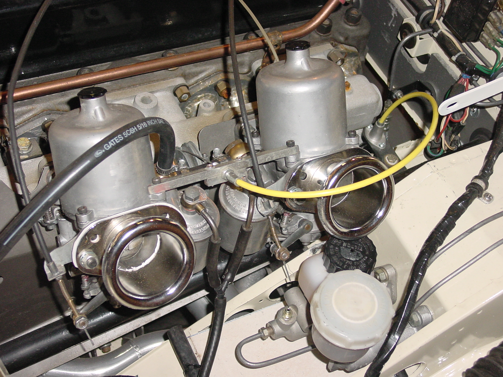
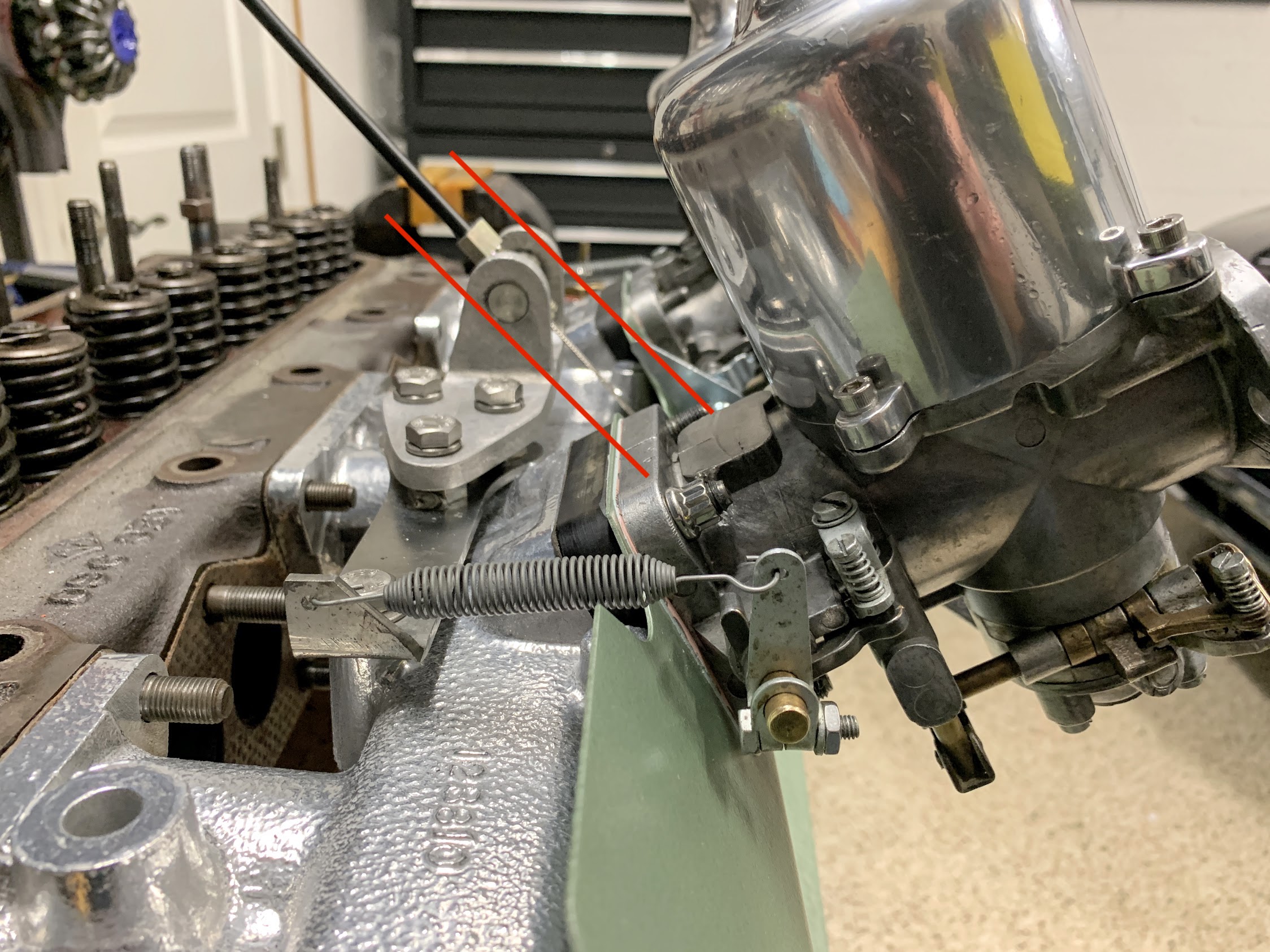
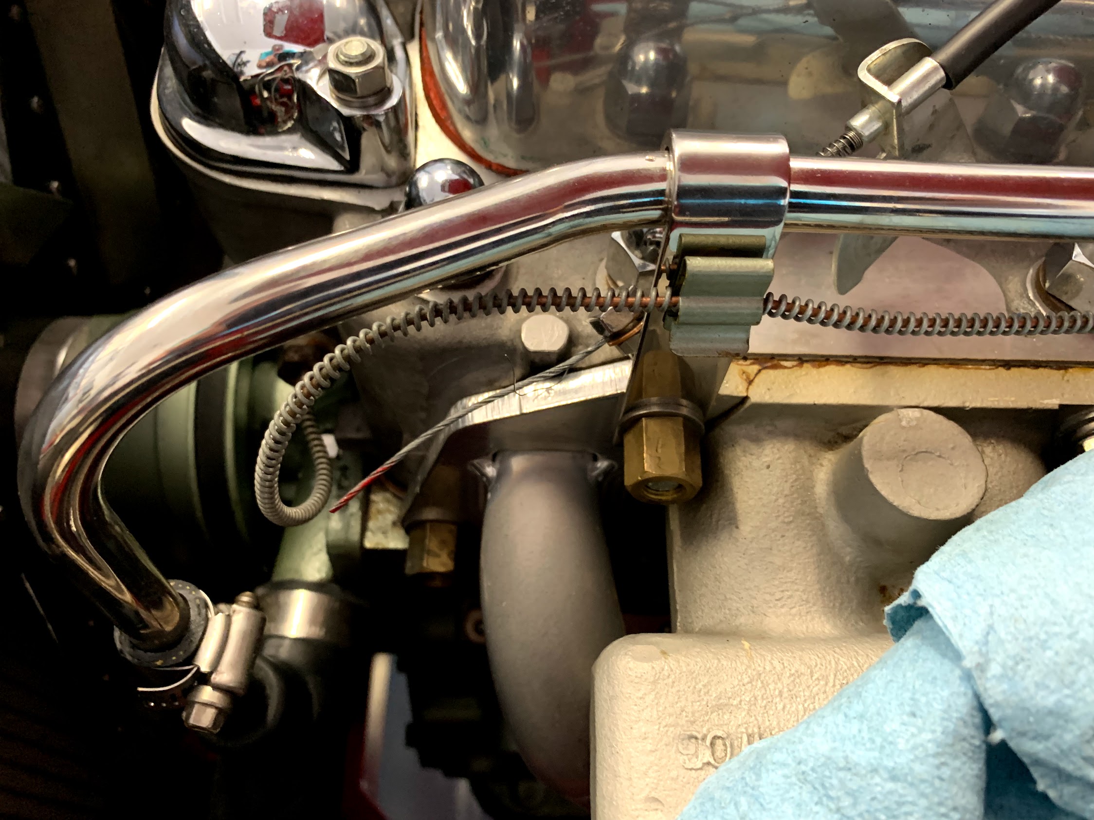
So, here is a step-by-step of the process from tear down to completion. More than anyone (except me) would want to know. I first removed the air cleaner that I have been using for ten years from the carbs. Next was removal of the throttle return springs with a note about orientation of the springs on the lever and the intake bracket:
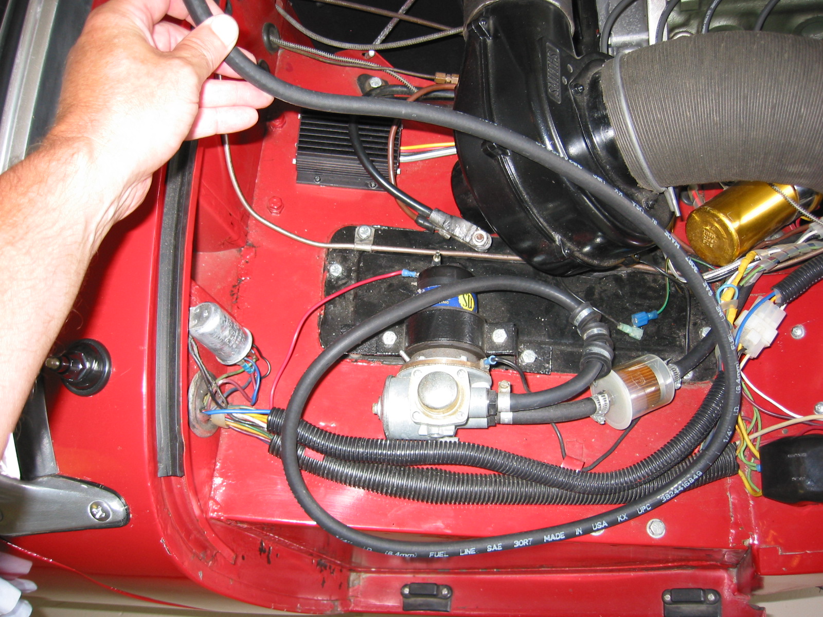
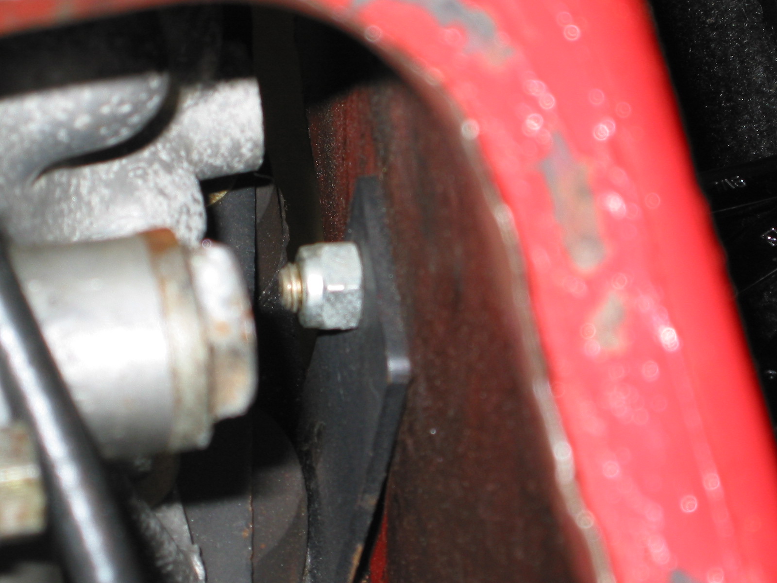
I had installed a fuel filter in the fuel line to the front carb. I removed the nut securing the filter bracket to the intake stud and then loosened the clamp at the front carb banjo and lifted the fuel line out of the way:
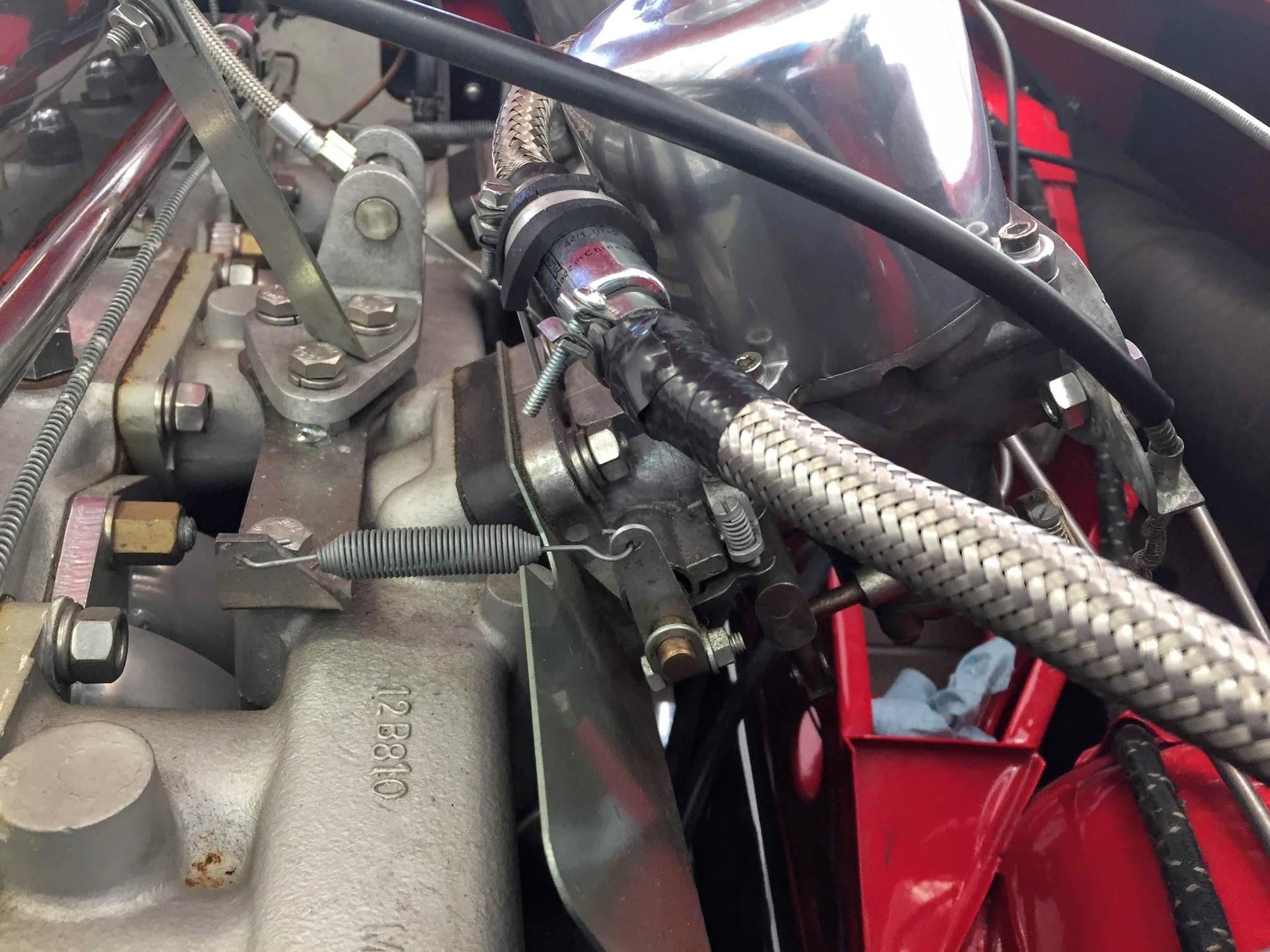
Front Throttle Return Spring
Then the hose connecting the two carbs could be removed:
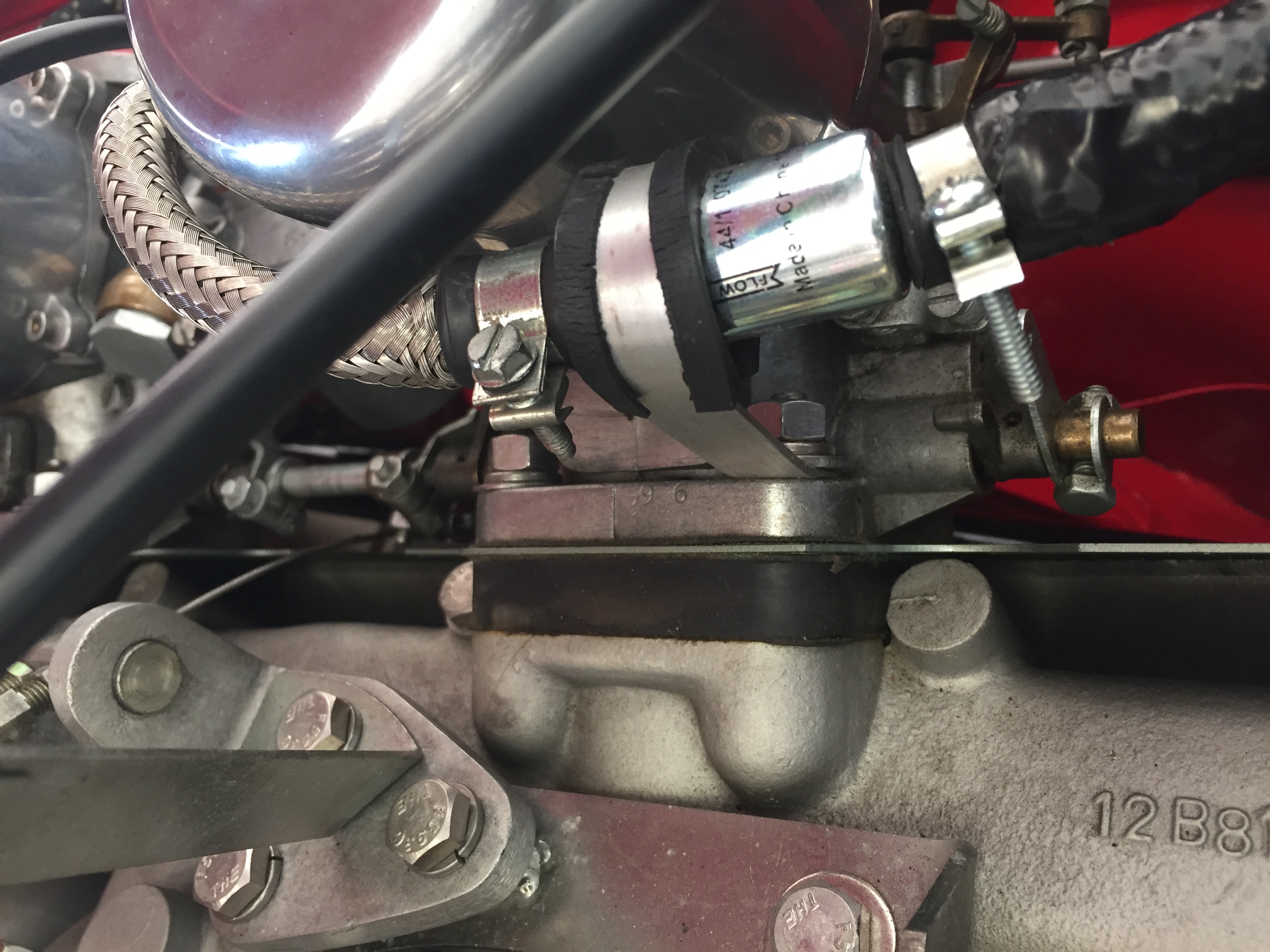
Fuel Hose Filter Mount

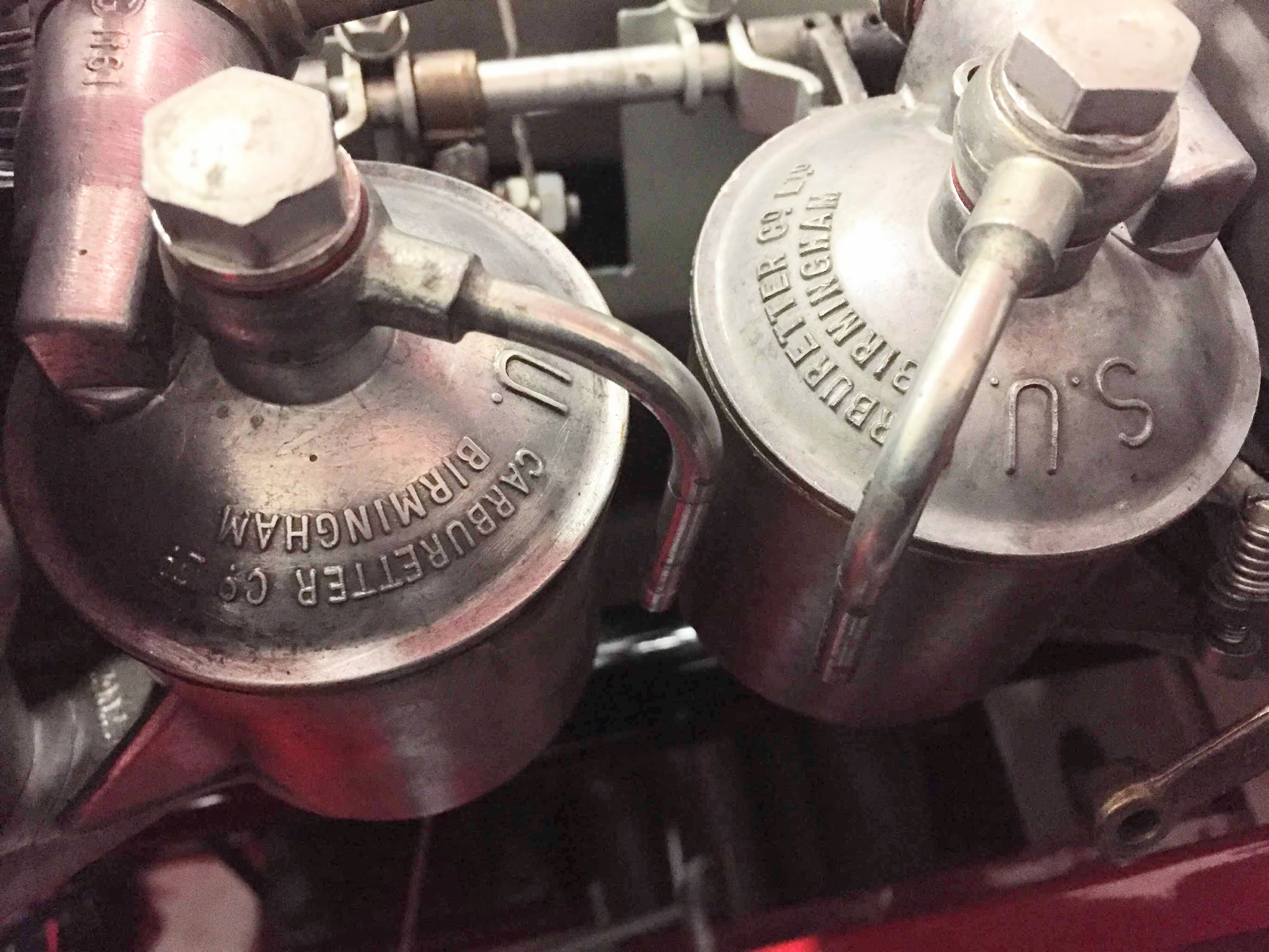
Banjos and Connecting Hose
I then removed the choke brackets from each of the Carburetters and loosened the cable retaining nut on each of the chicken levers, so that the cables were free. There are three (3) ballpoint pens springs in the cable to make the cable retract. I left the spring-loaded cable in tact.
Rear Choke Cable and Bracket
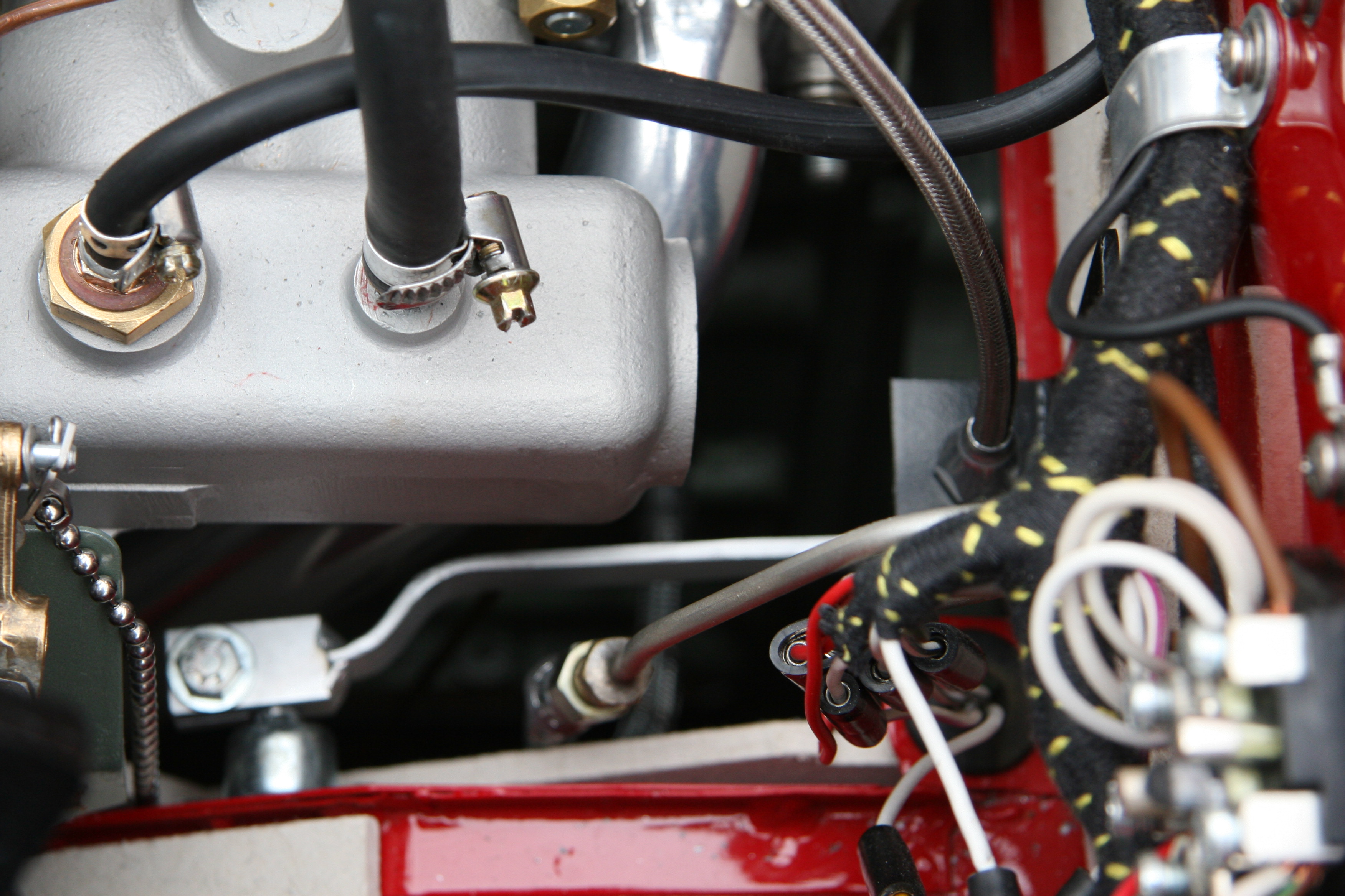
The rubber hoses from the overflow pipes at the float bowls were then removed. The float bowl banjo nuts are removed with a 1/4 inch Wentworth wrench. The hoses run through a hole in the insulated het shield.
Overflow tubes removed from float bowl drain pipes
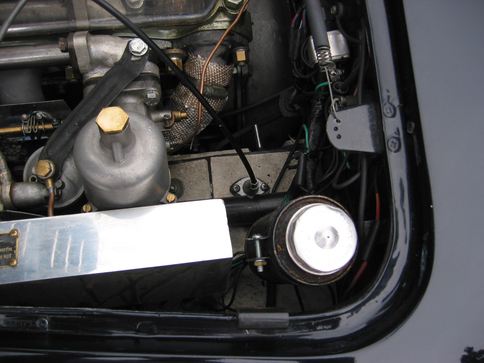
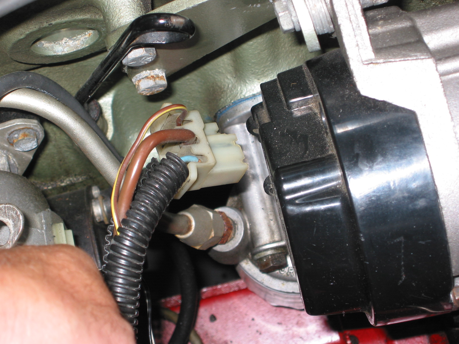
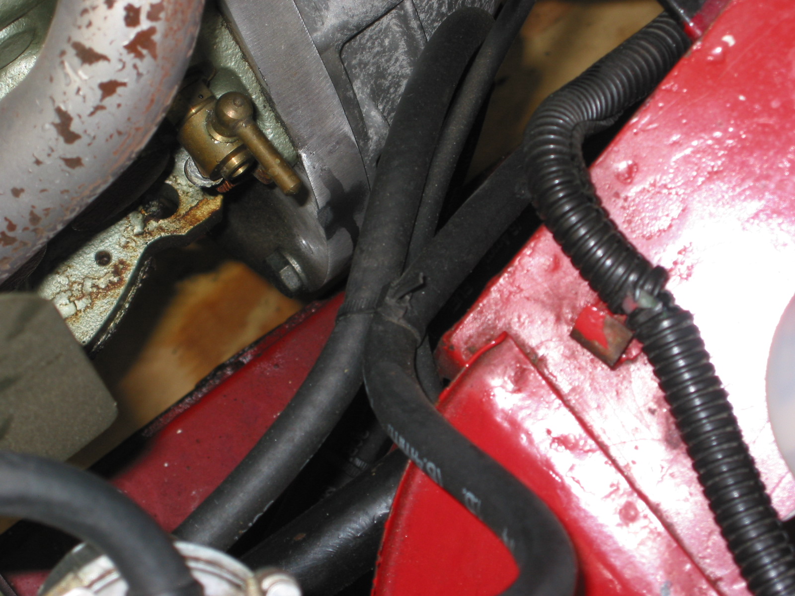
I then disconnected the vacuum line at the rear carburetor that connects to the distributor.
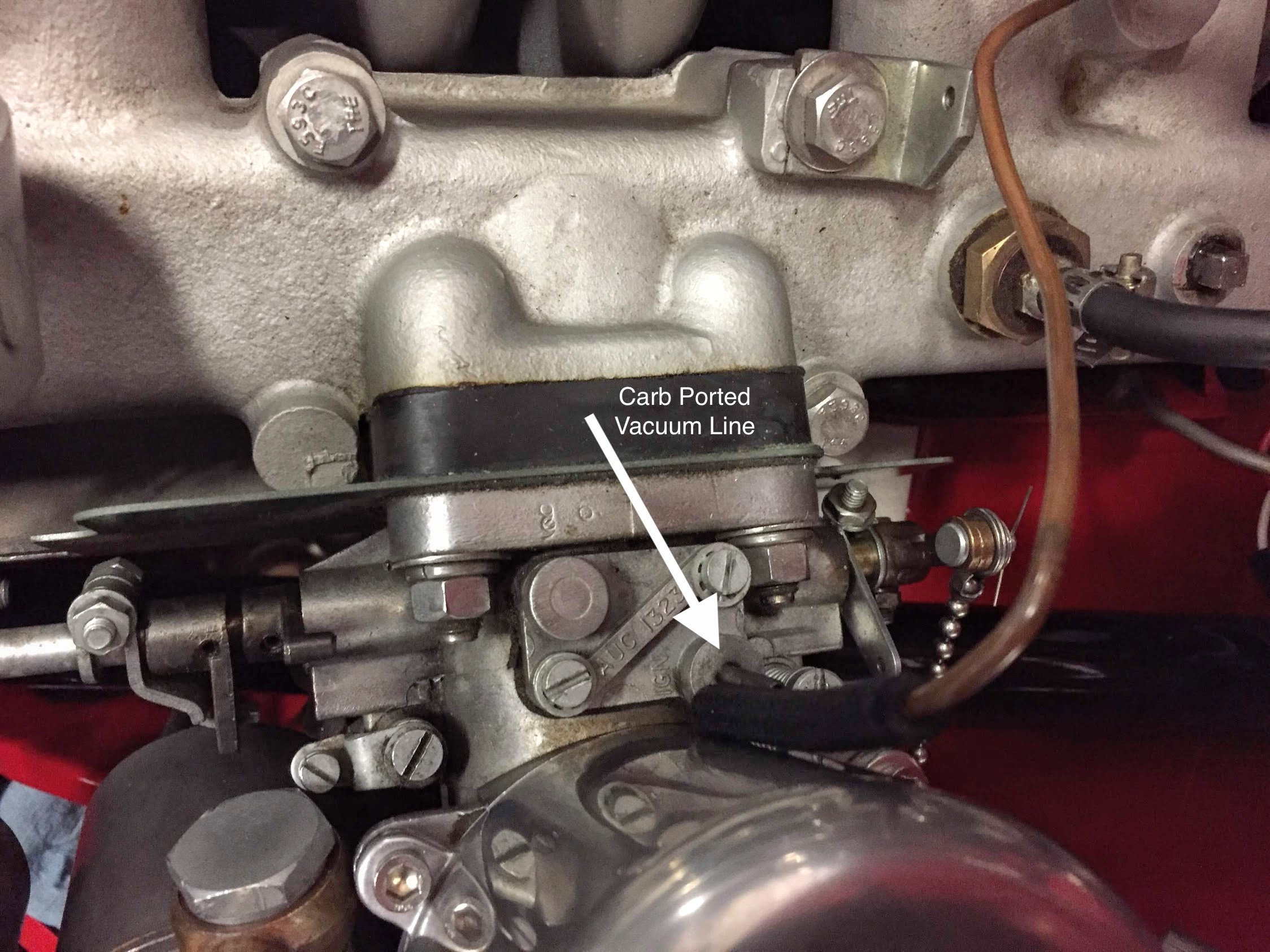
Carb Ported Vacuum Line
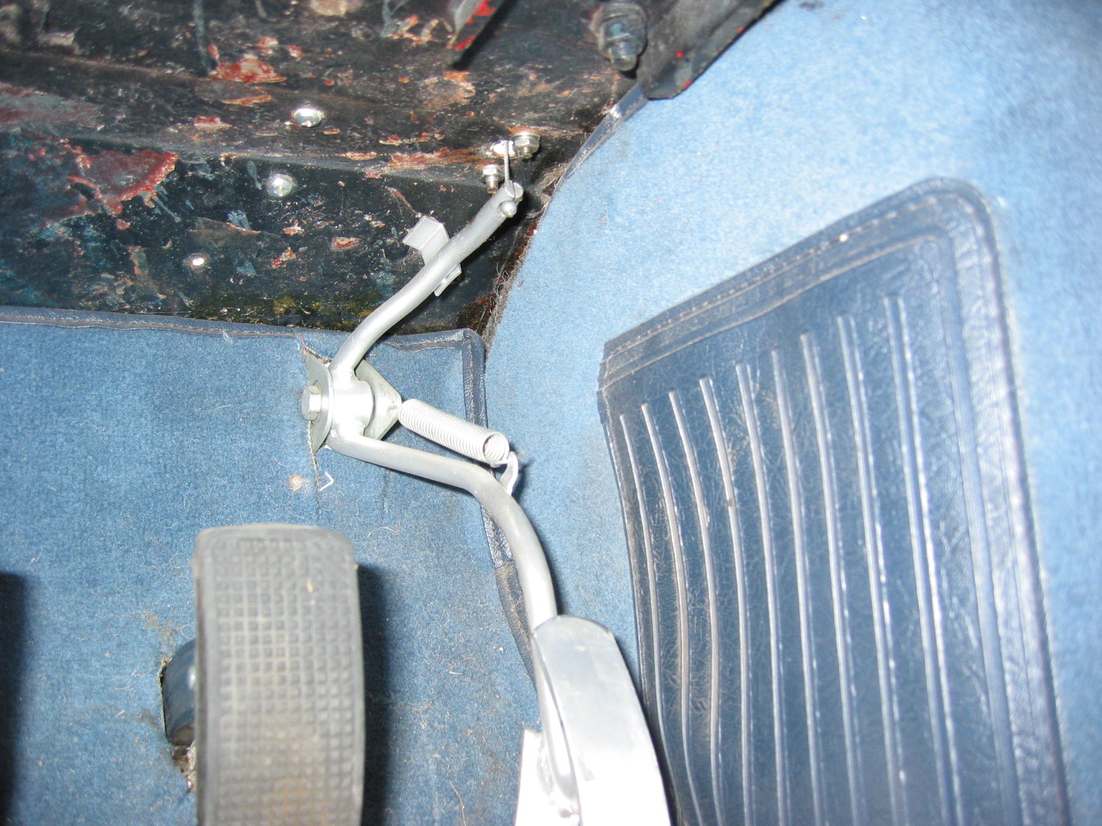
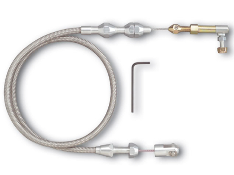
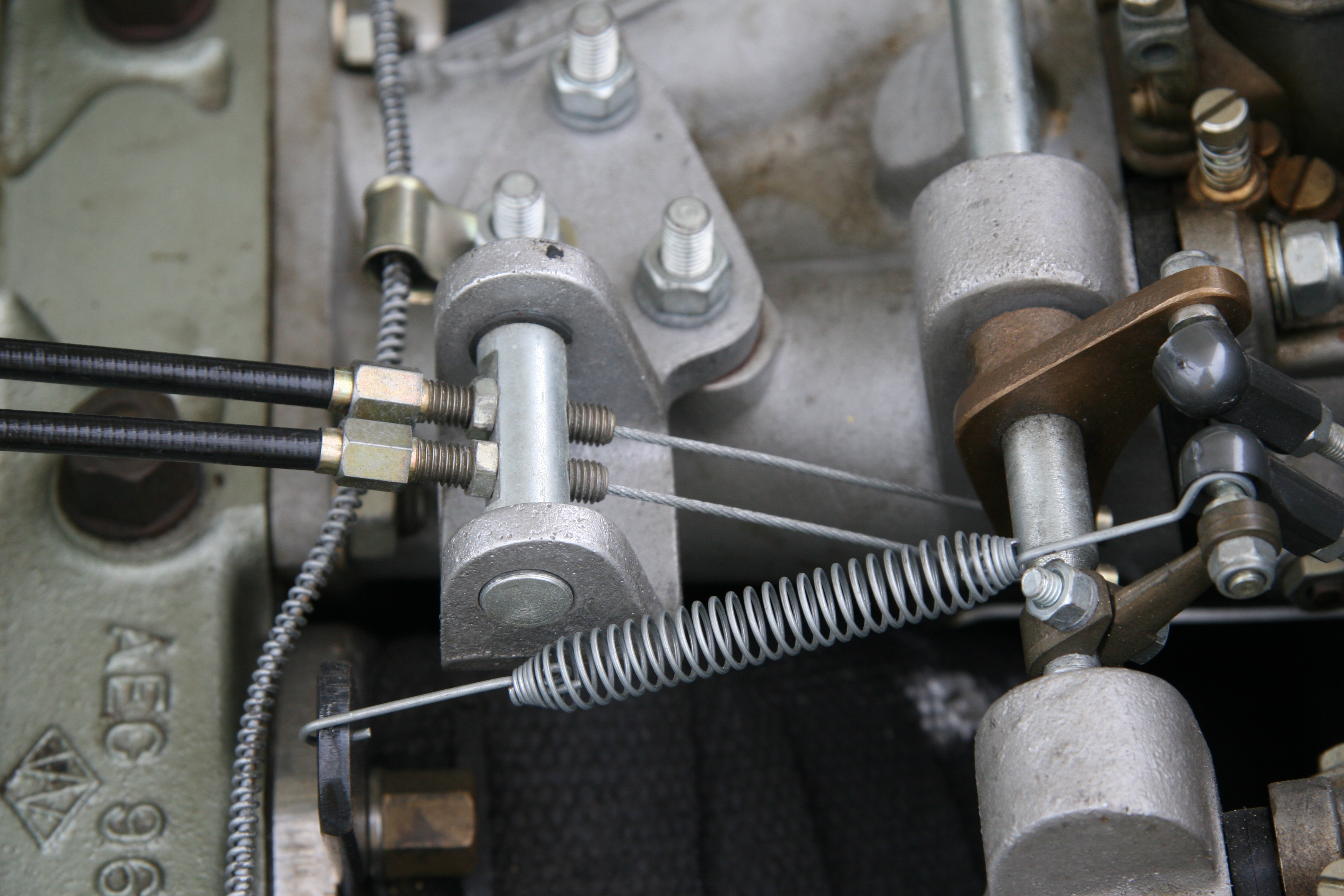
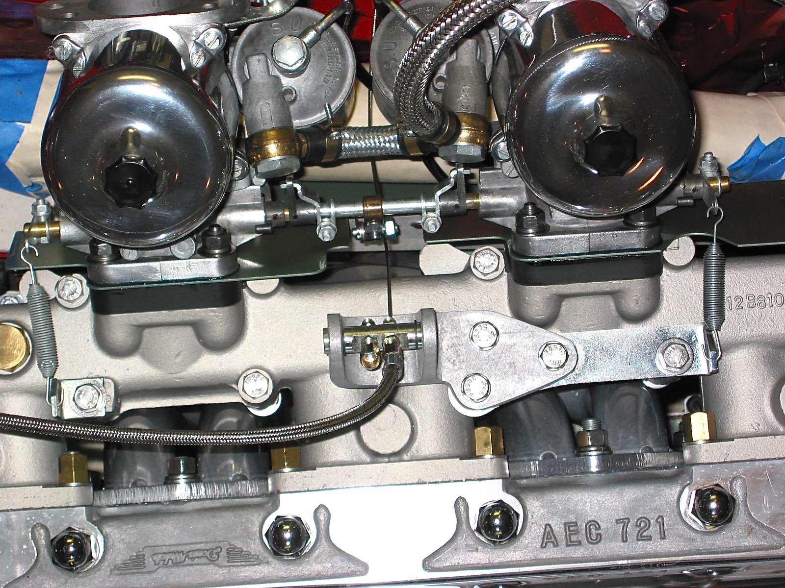
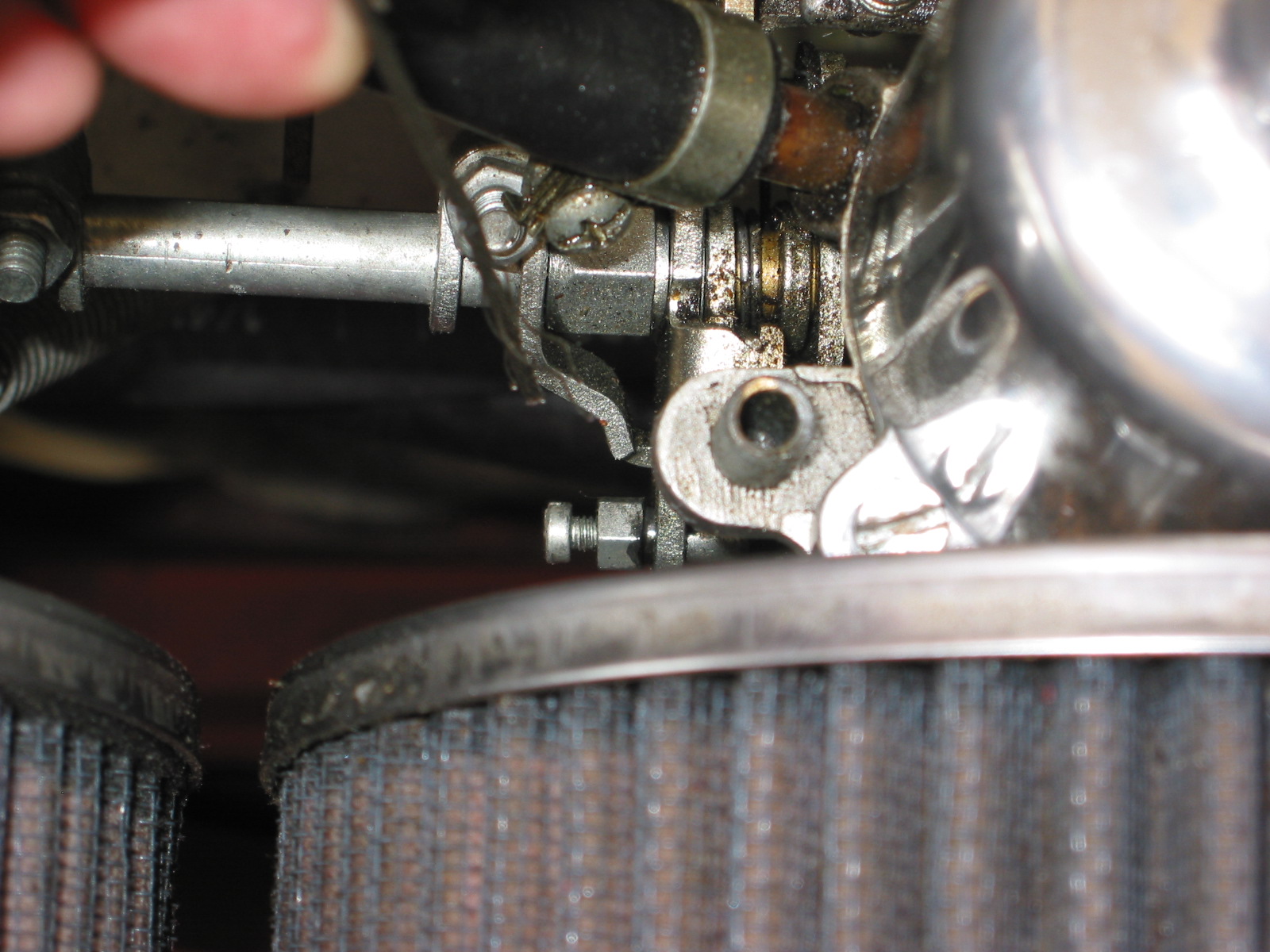
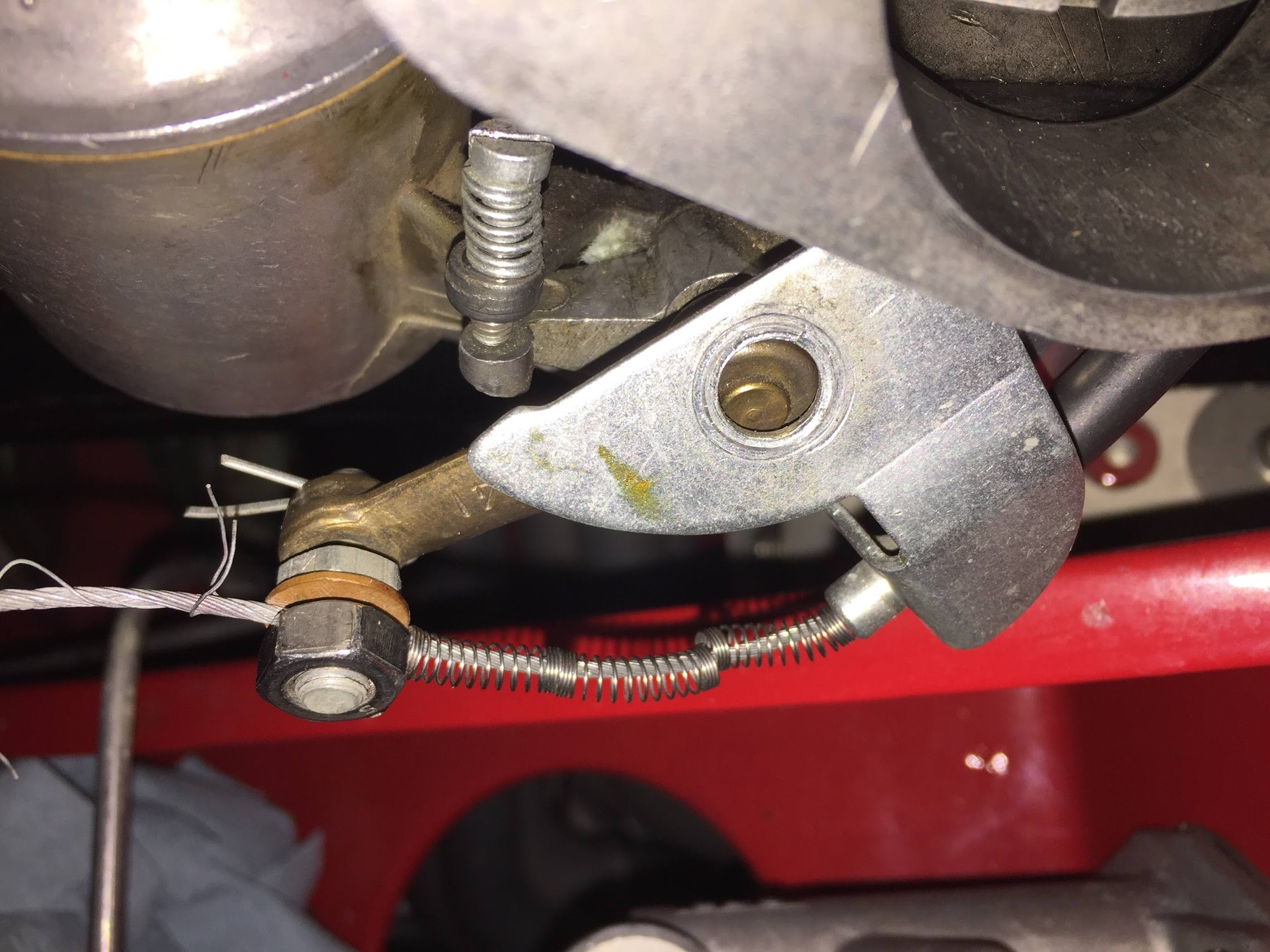
The next step was to disconnect the throttle cable from the throttle lever located between the carbs.
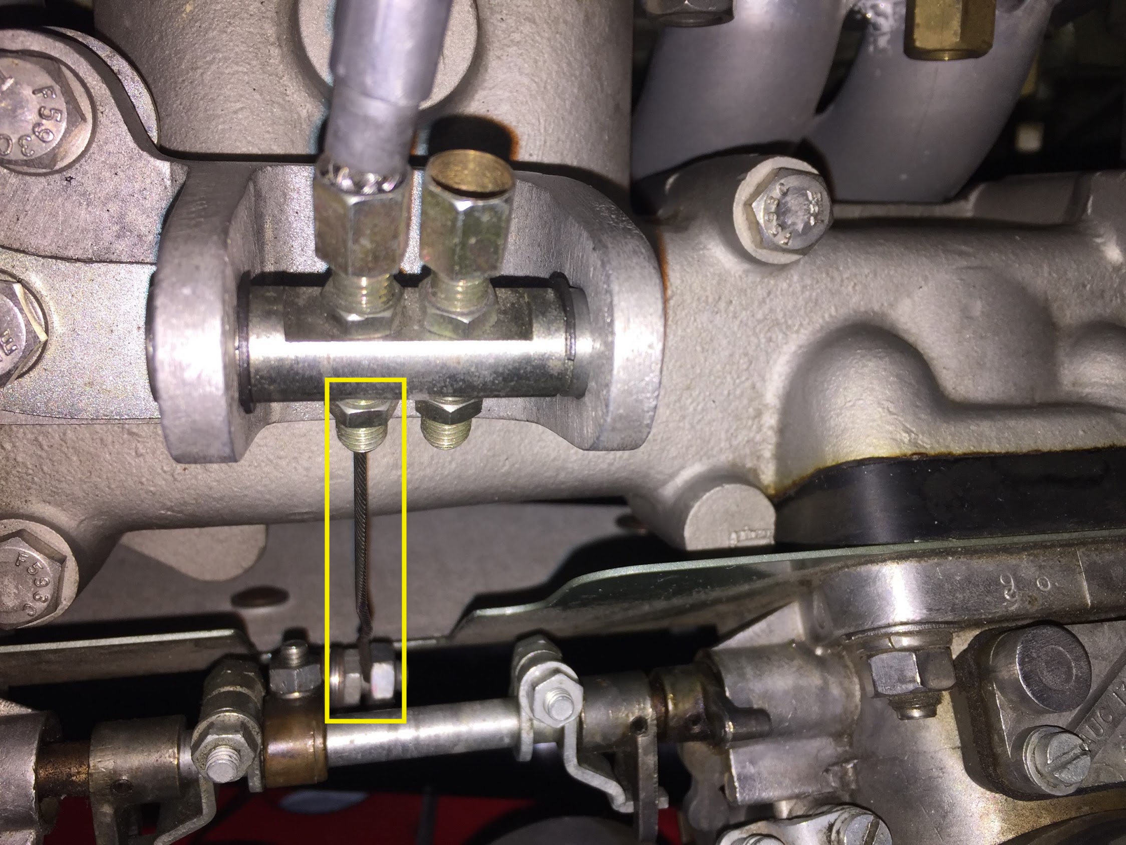
Throttle Cable and Lever
Throttle Cable and Lever Orientation
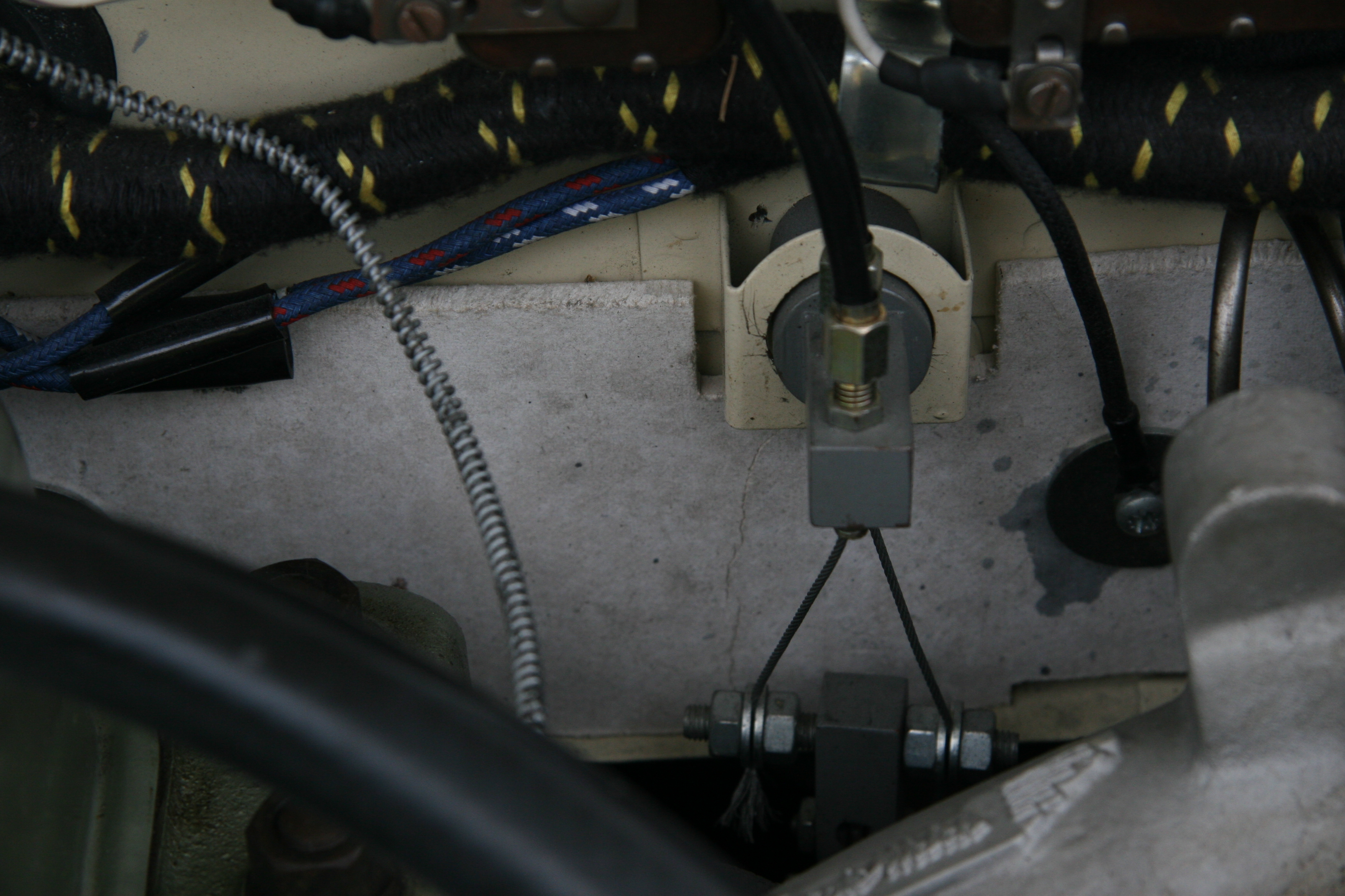
The cruise control chain was then disconnected from its throttle shaft lever. The relative clock location of the cruise control lever and the throttle shaft lever were noted.
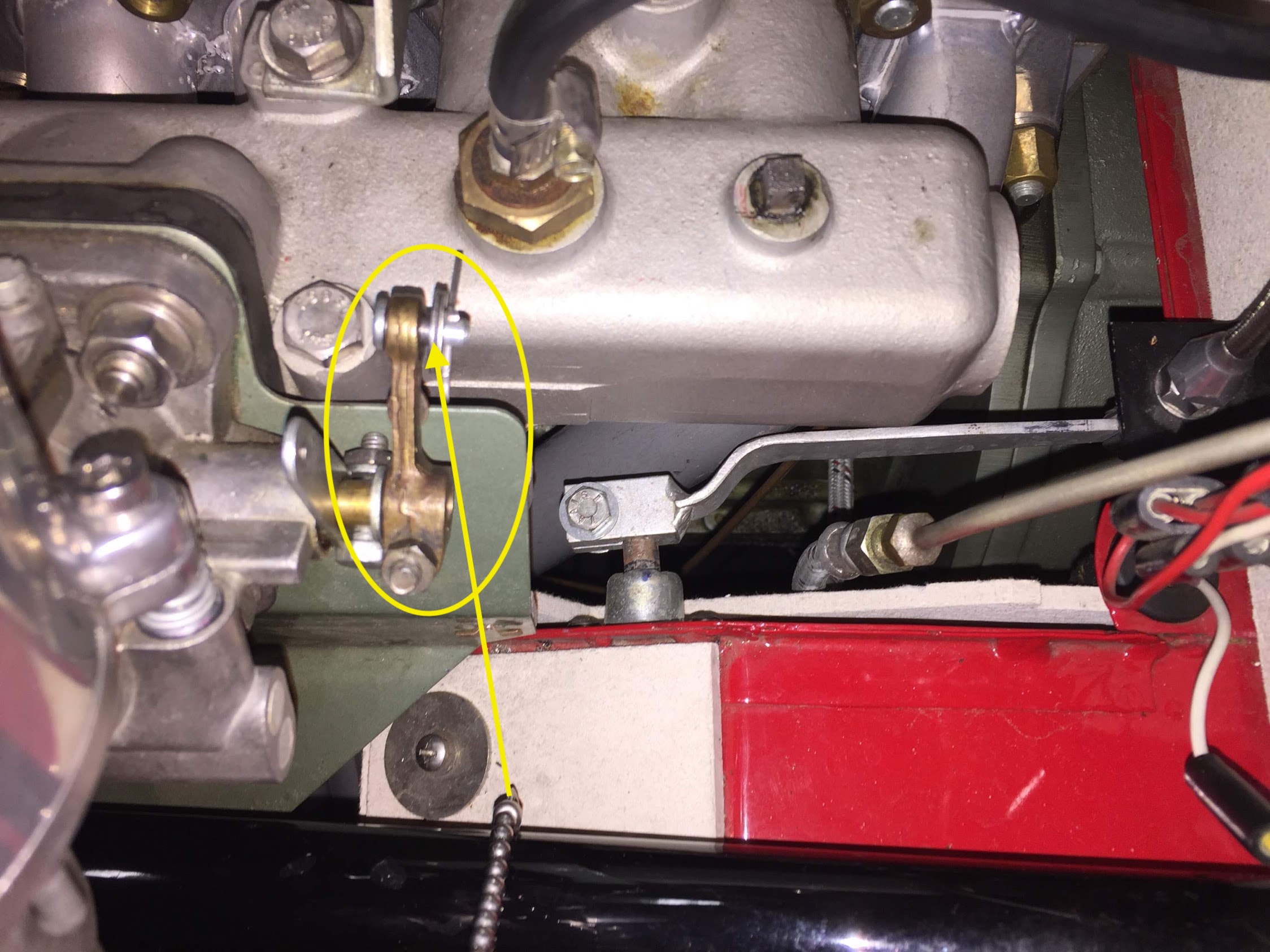
Cruise Control Lever and Chain
With all of those components disconnected, it is then possible to remove the carbs from the intake manifold. This is done by loosening and removing eight 5/16″-24 hex head nuts, flat washers and lock washers from the manifold studs. By the way, getting to the lower studs can be a challenge! Before lifting away the carbs and float bowls check to see if the float bowls are empty of fuel.
Carbs removed from eight intake studs
It is then possible to remove the heat shield from the manifold. There is a gasket on each side of the heats shield between the carb and the heat shield and between the heat shield and the manifold.
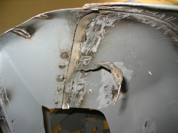
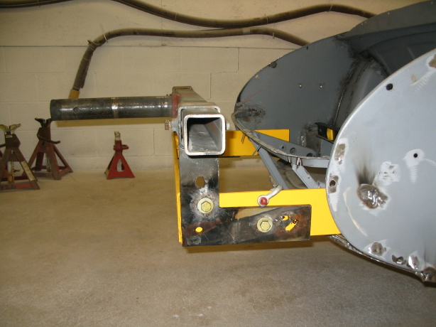
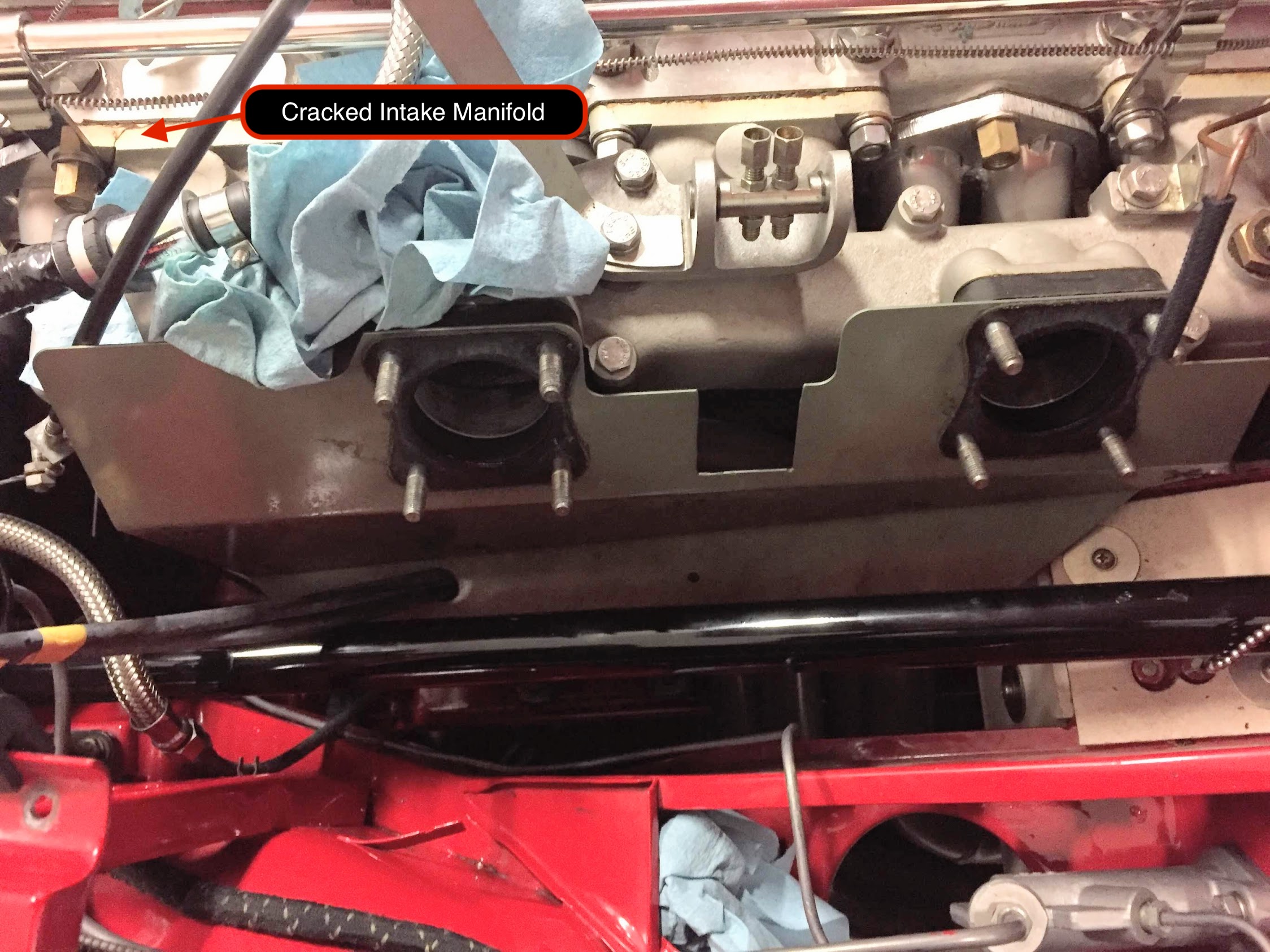
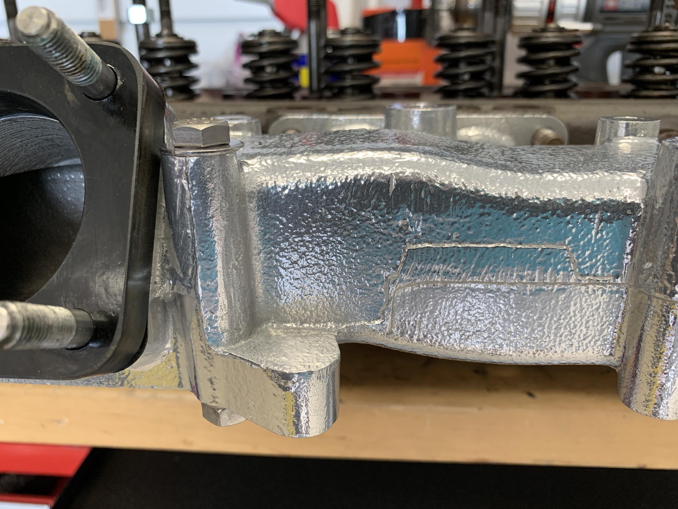
My intake manifold had a crack in the front mounting ear. It can be seen in the upper left of the image above. I located another used manifold from Michael Salter. I had the manifold Jet-Hot coated which gave it an almost chrome appearance. So while the carbs were being tended to, it was the perfect time to go ahead and replace the manifold. Several steps are needed to remove the manifold.
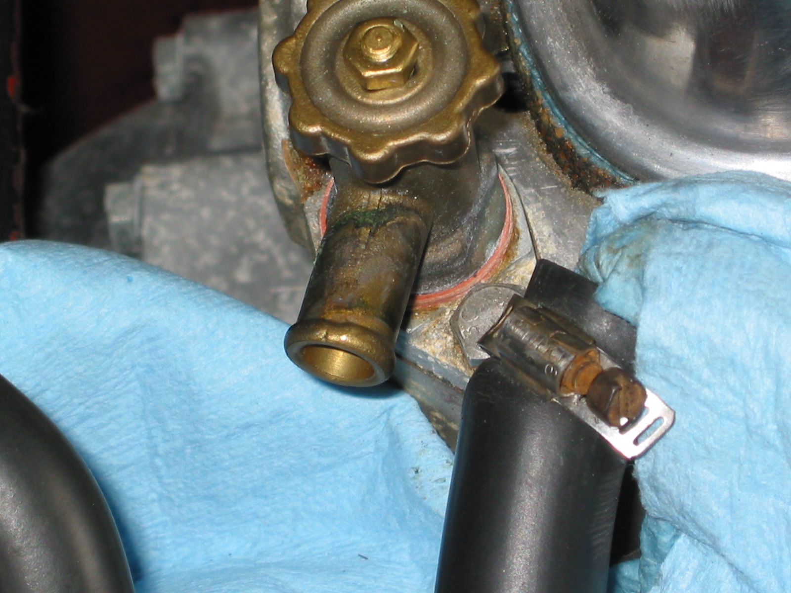
First was to detach the vacuum hose from the rear port on the intake that is used for the cruise control.
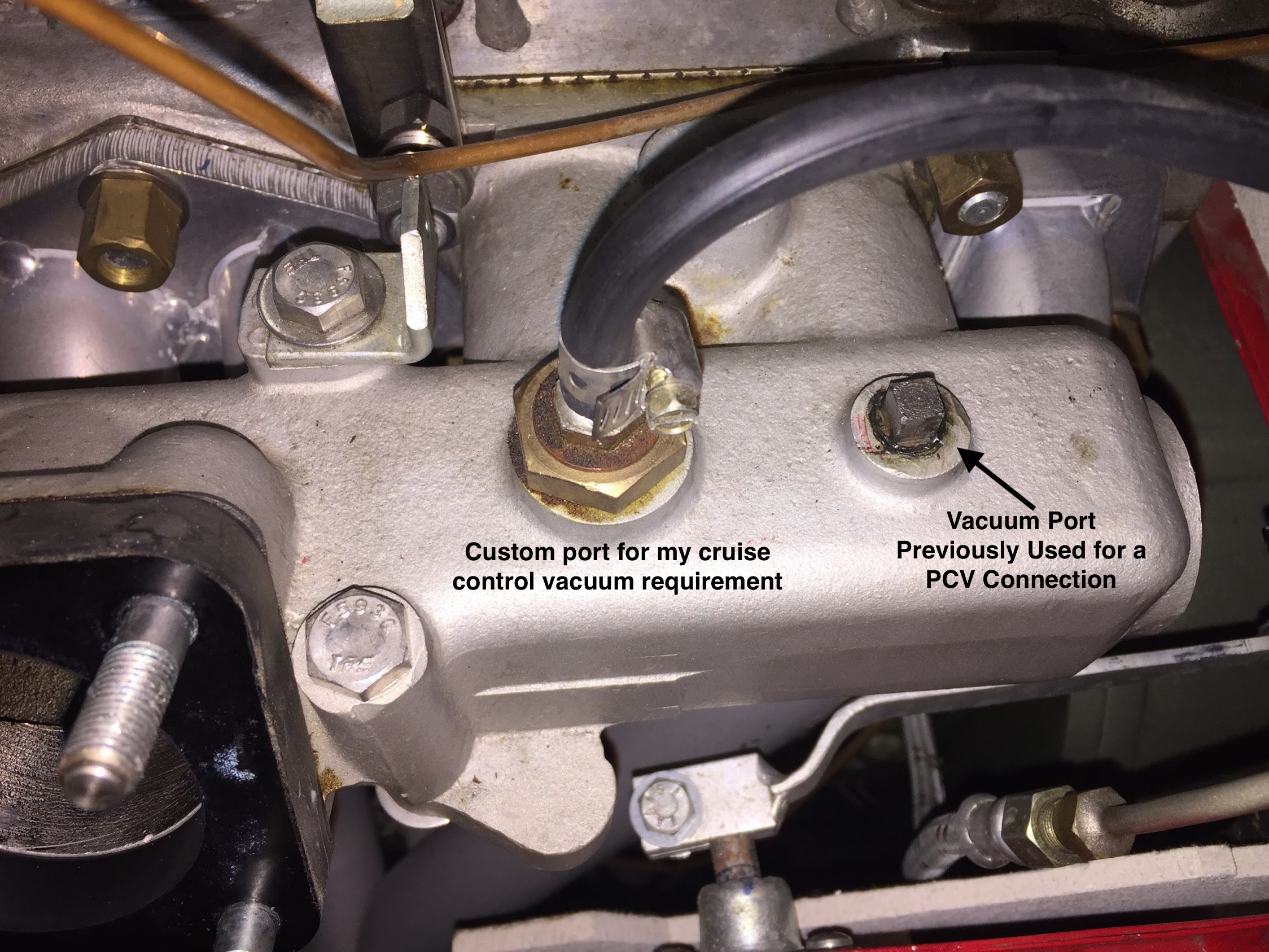
Vacuum Port for Cruise Control
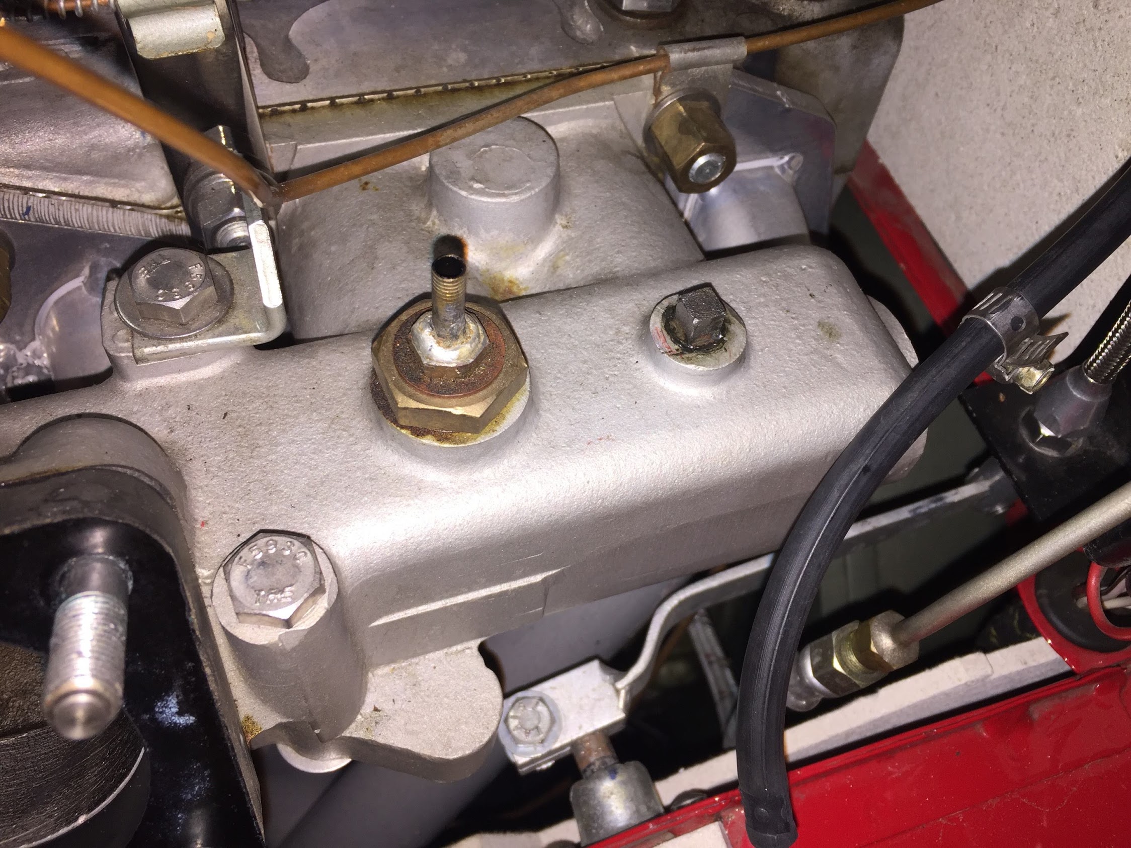
Custom Vacuum Port for Cruise Control
I then removed the front choke cable from the throttle bracket on the intake manifold.
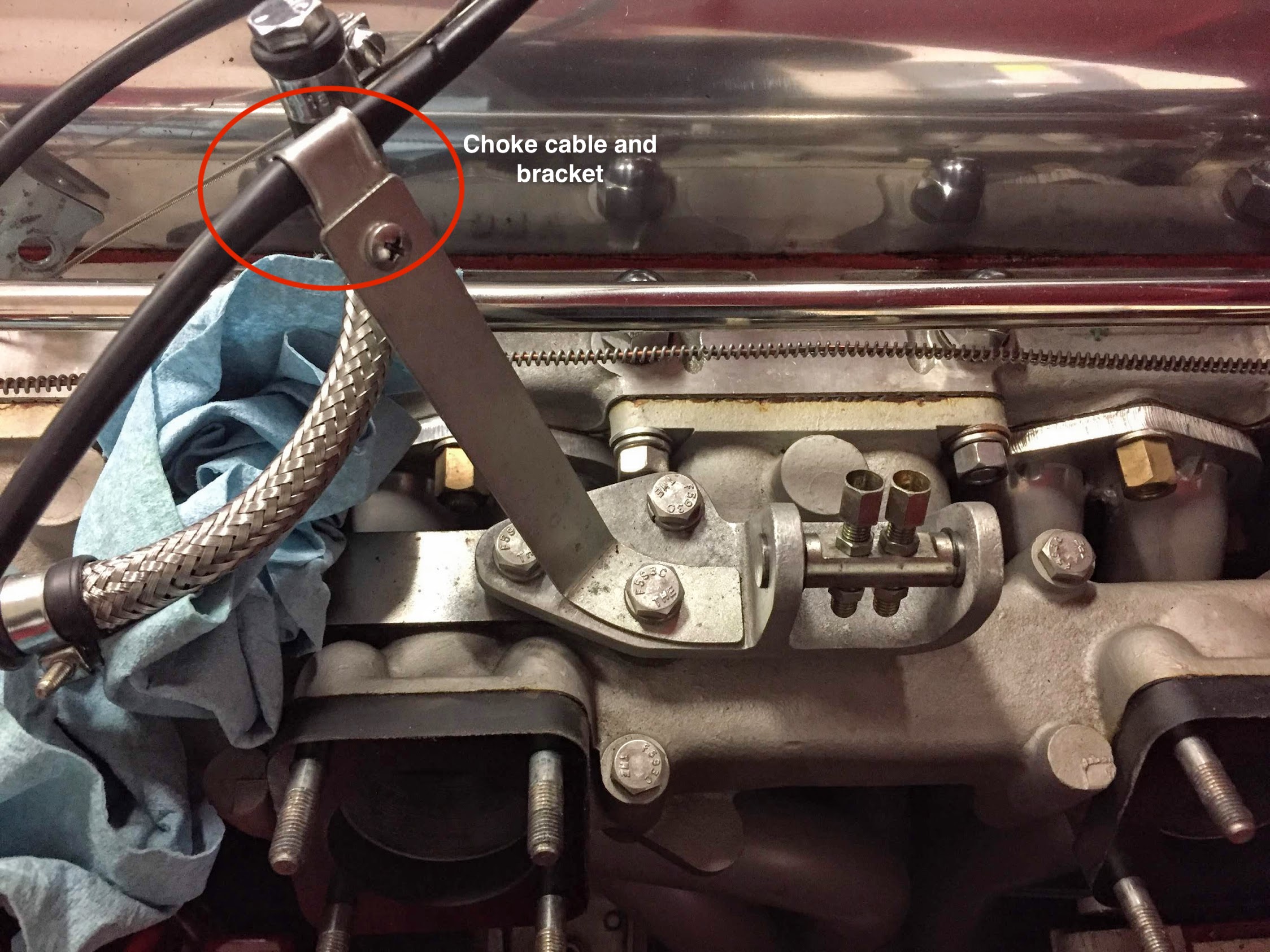
Choke Cable and Bracket Mount to Intake Manifold
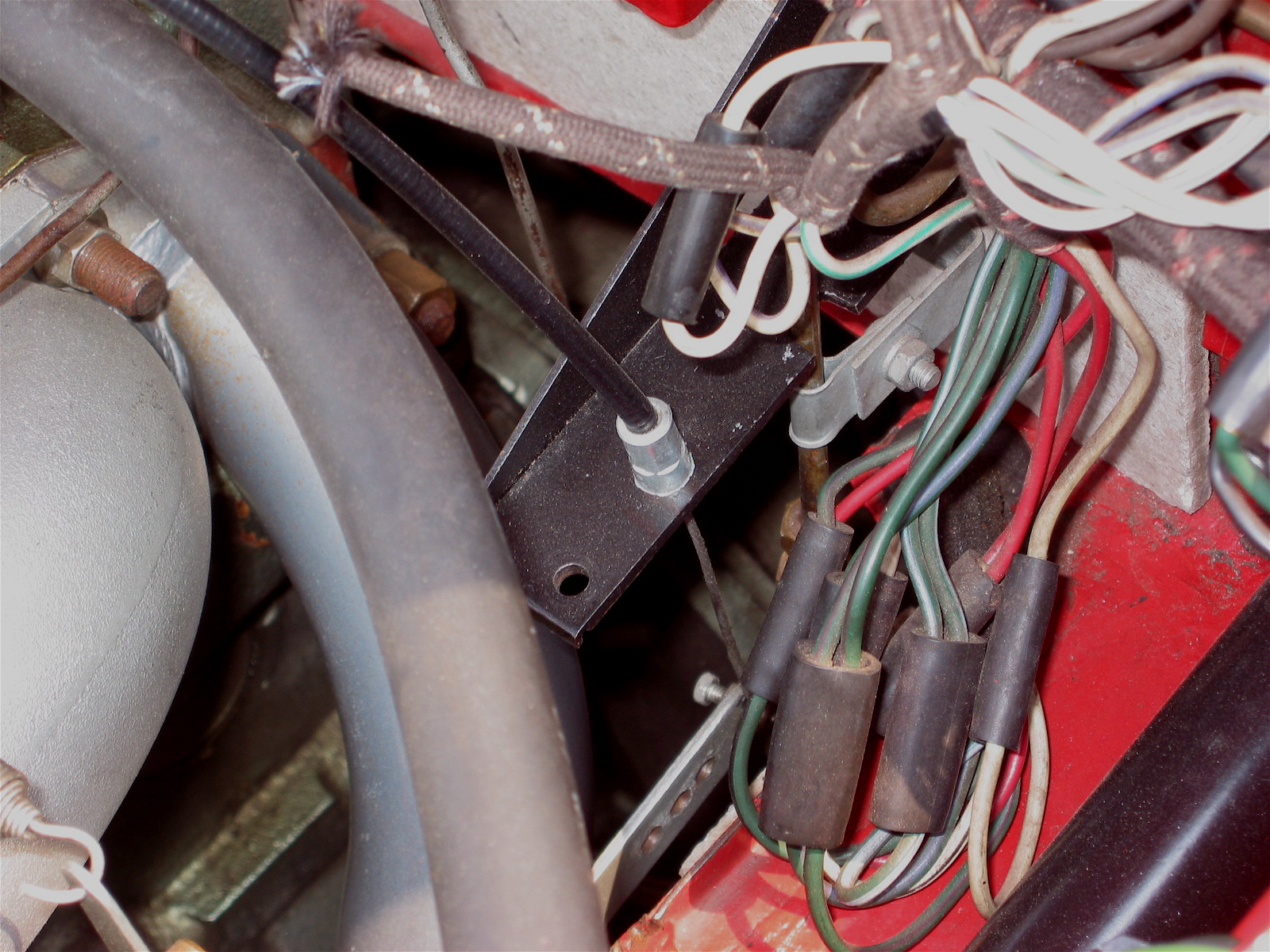
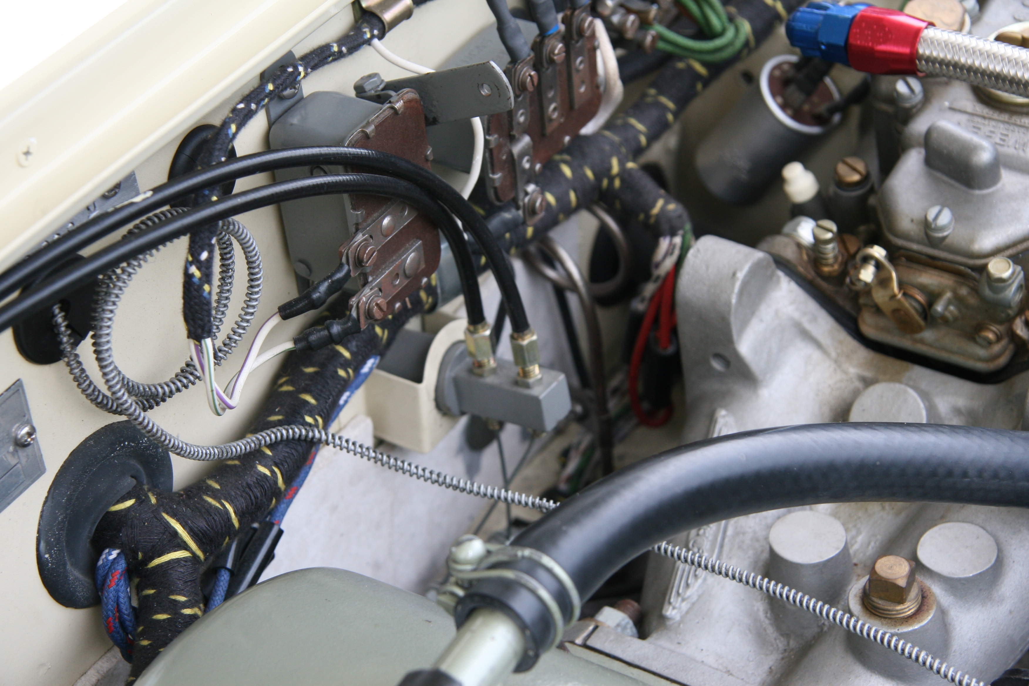
The next step is to remove the remaining two bolts that hold the throttle cable bracket to the intake manifold. This will reveal the lower bracket which has two mounting bolts to the intake manifold.
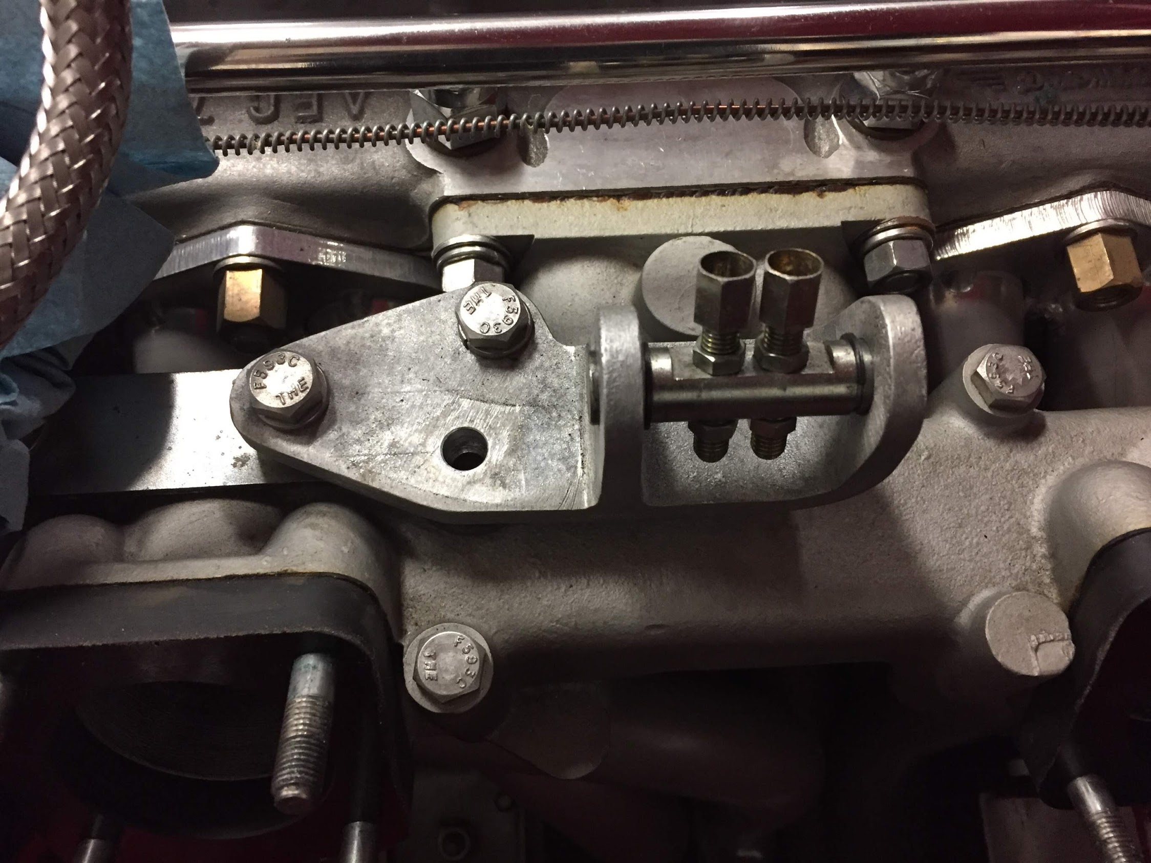
Upper Portion of the Throttle Bracket
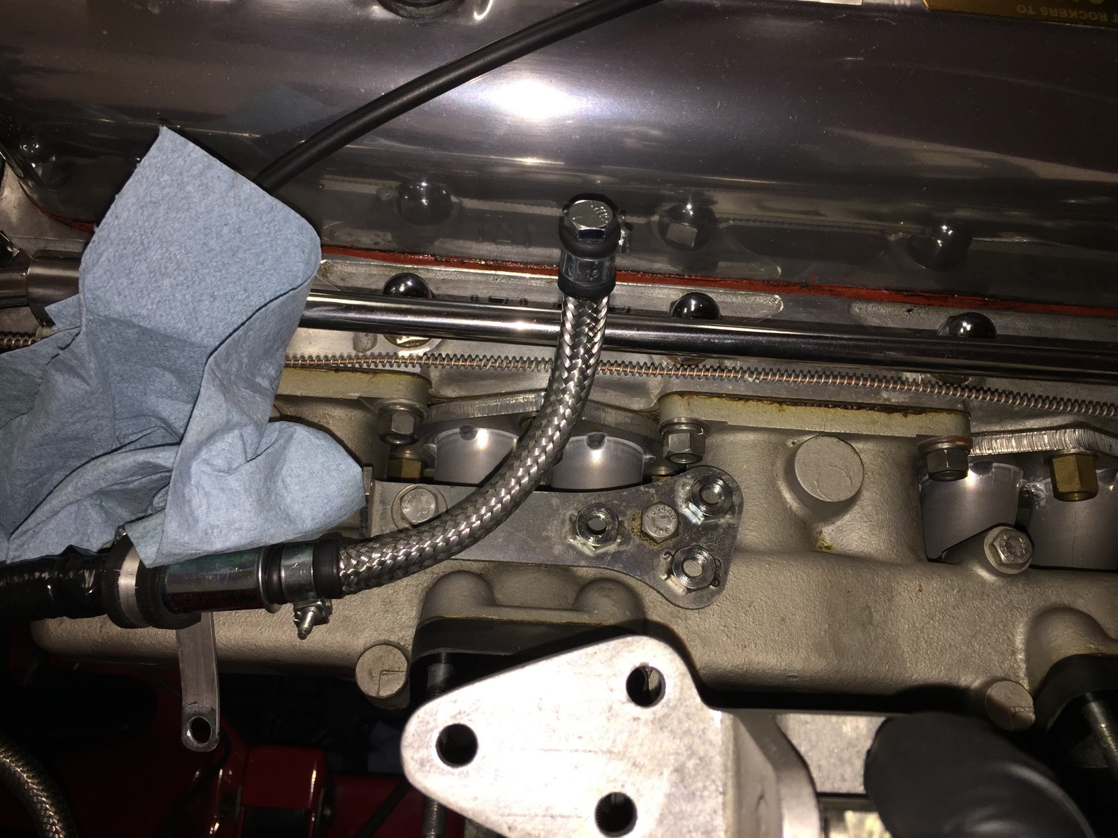
Lower Portion of Throttle Bracket
Then remove the two bolts holding the lower bracket. Lift away the lower bracket. The rear bolt is only about a half inch long. But the front bolt extends through the intake manifold and has a nut on the reverse side.
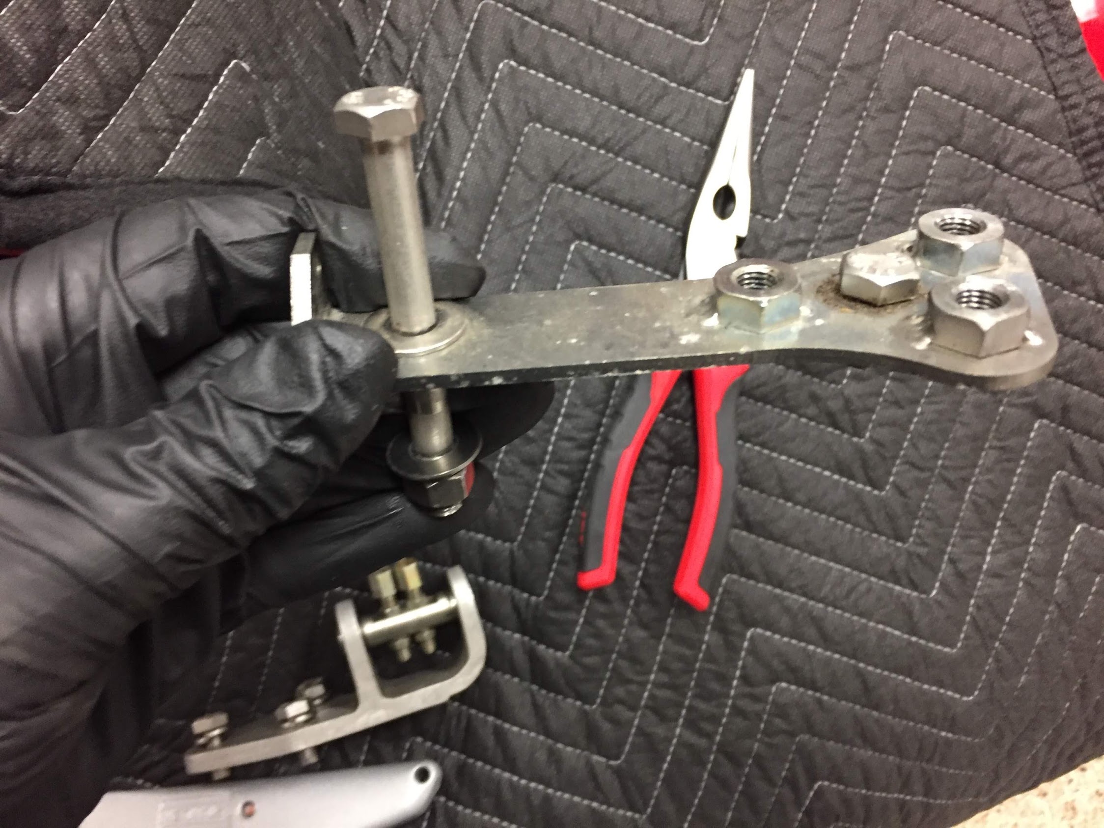
Lower Portion of Throttle Bracket Removed
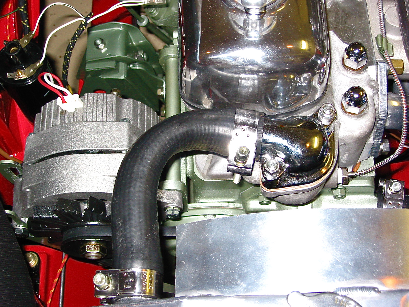
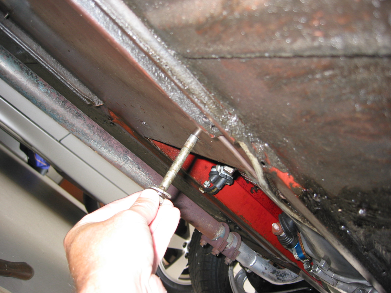
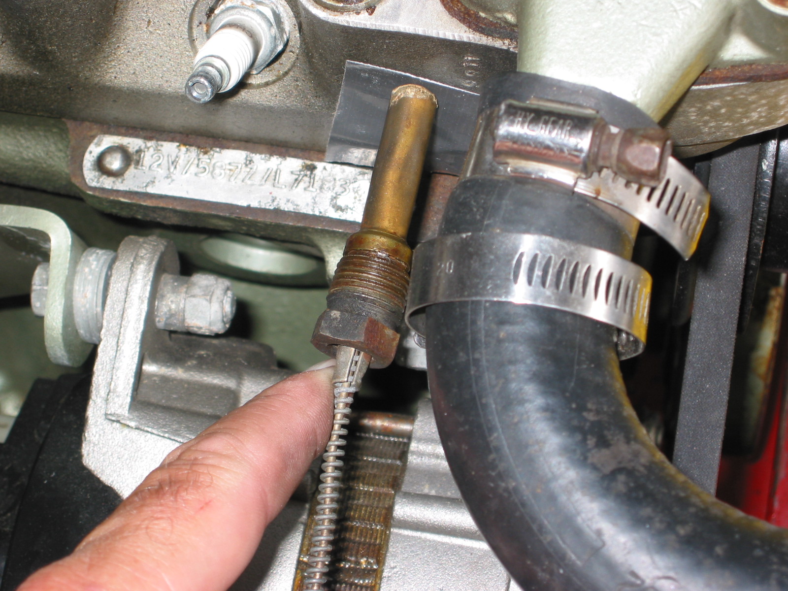
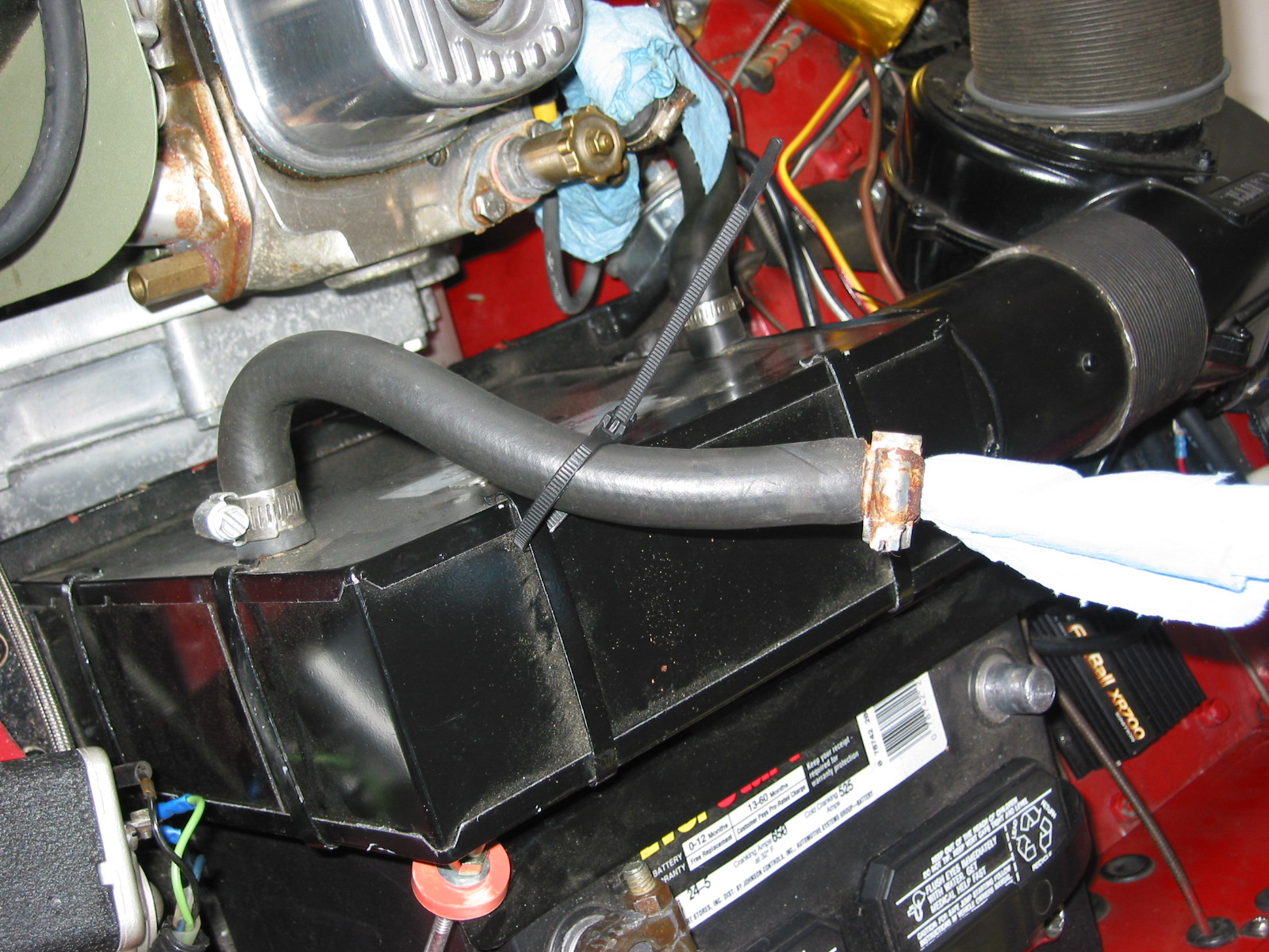
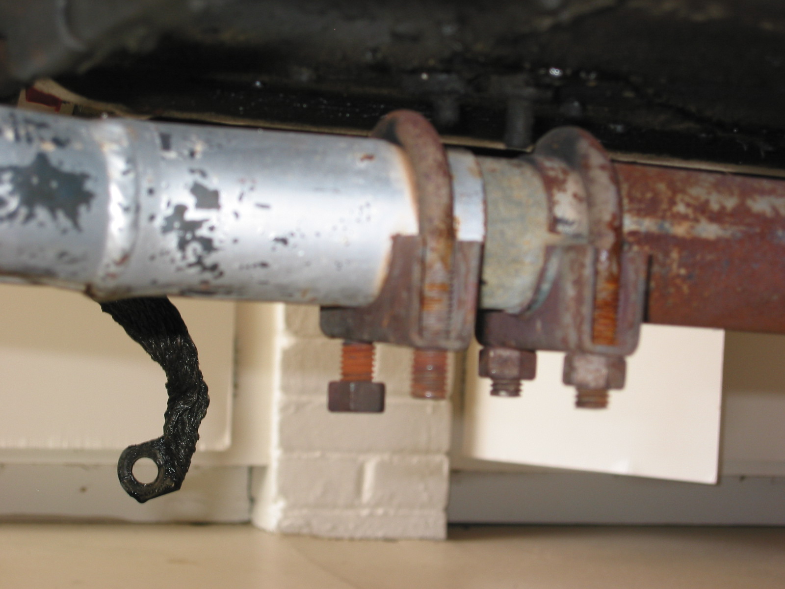
The water pipe for the heater is mounted in two locations and these must be loosened to permit the removal of the intake manifold. This requires loosening the clamp on the radiator hose extension. You lose a little coolant, but not too much. The pipe can then be lifted aside allowing access to the manifold. I also unclipped the water temperature sensor cable from its clips. In the image below it is easy to see the crack in the manifold ear.
Front Heater Pipe Mount

Rear Heater Pipe Mount
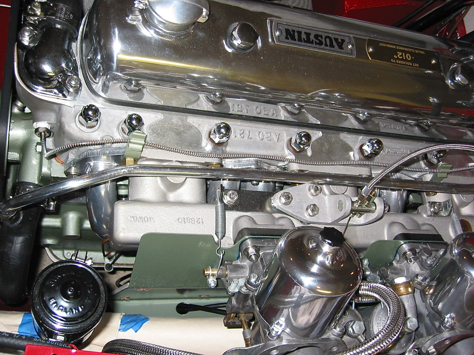
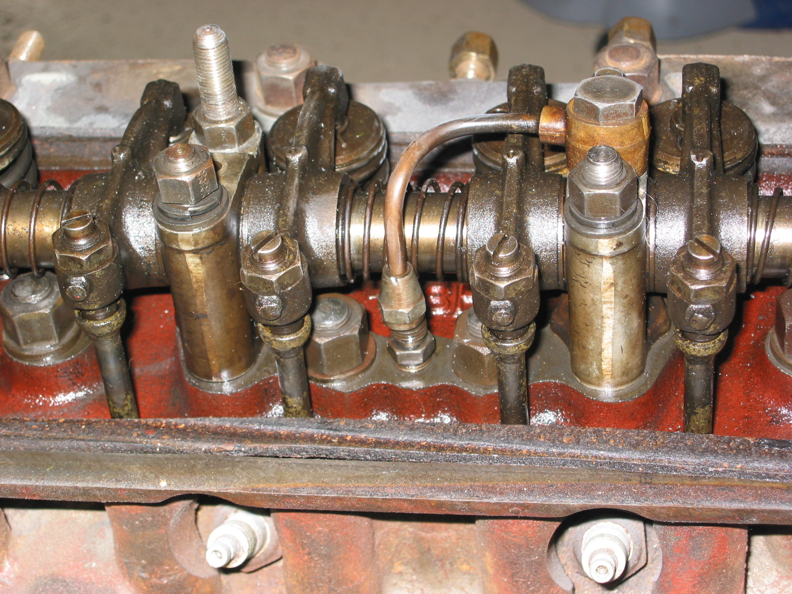
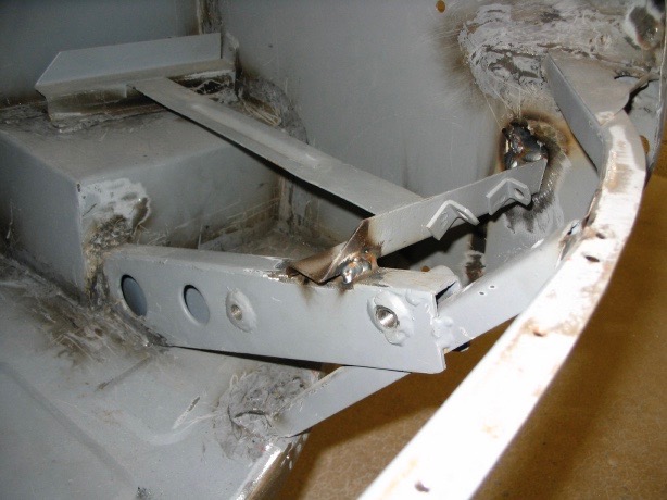
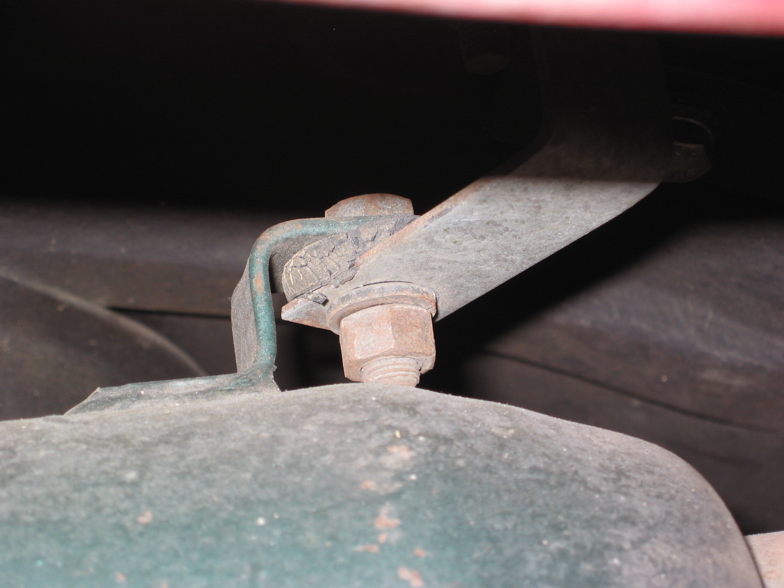
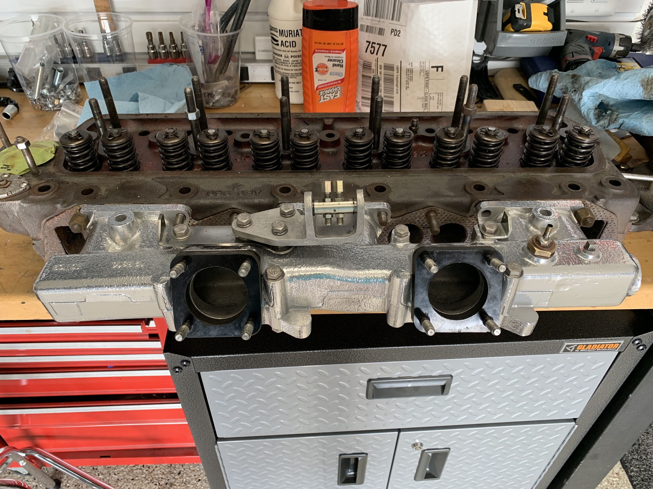
The nine nuts, flat washers and lock washers could then be loosened and removed allowing the removal of the manifold. The front and rear mounting points for the intake share a brass nut fixing the exhaust headers to the head. I noticed that the exhaust header mounting plate is not quite as wide as the intake mounting plate which probably stressed the aluminum intake ear, hence the crack. On the newly prepared intake manifold, I filed the forward and rear mounting ears down so that they aligned nicely with the exhaust headers. This should prevent cracks in the future.
I had saved my original iron cylinder head and it came in handy on my workbench for setting up the intake manifold and carbs. The weight of the head supports everything and makes mocking up everything and adding intake components much easier than working in the car!
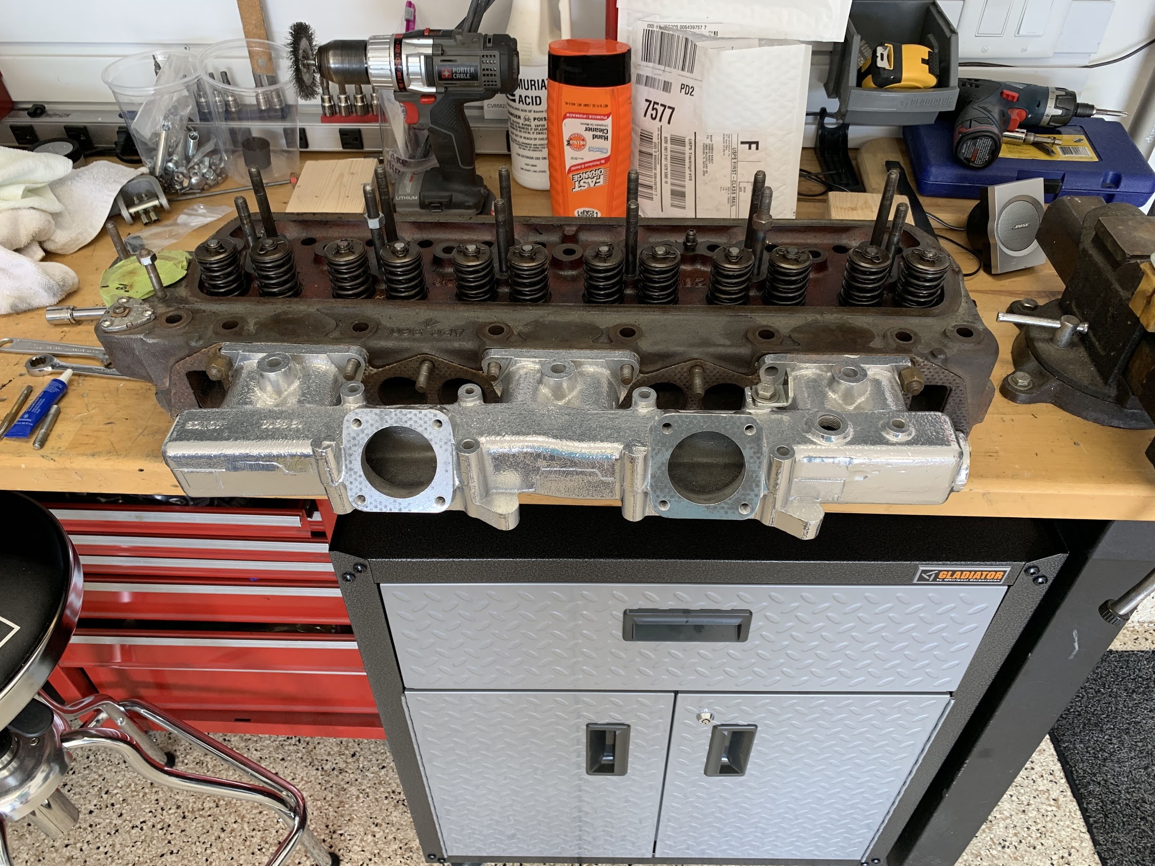
Original Iron Head with Newly Prepared Intake
I double-nutted and removed the carb mounting studs from the old manifold and installed them in the new manifold after chasing all of the threads to clean them out. I used compressed air to blow out all of the stud mounting points.
Removing Studs from Old Intake Manifold
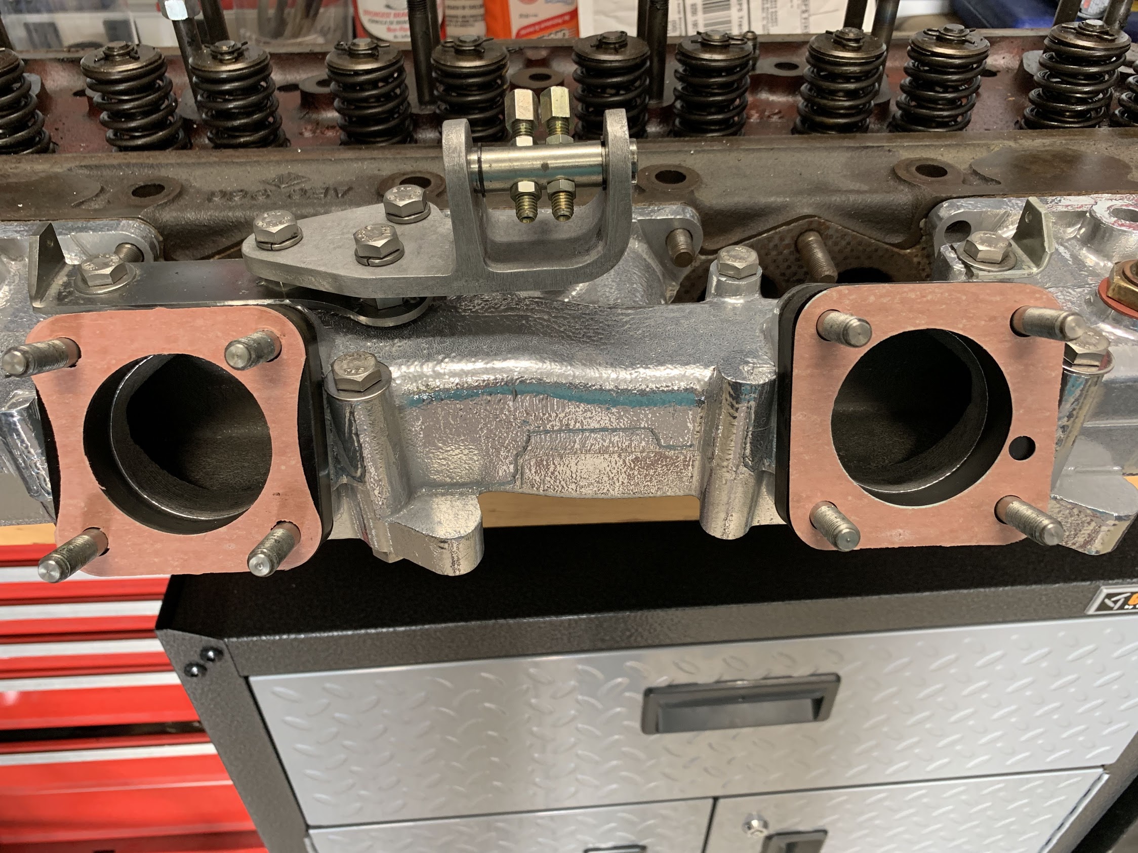
After installing each of the studs into the intake manifold I placed one gasket and then the spacer block on the manifold.
Studs, Gaskets, and Spacer Blocks Installed
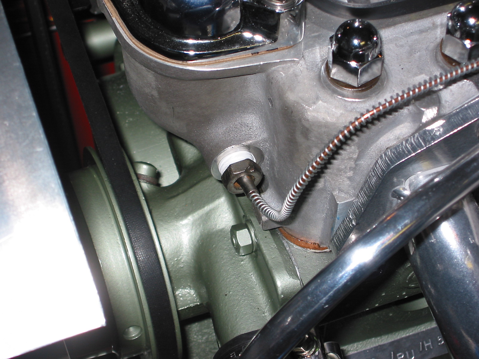
I removed the fitting for the vacuum used for the cruise control from the old manifold and reinstalled it in the new manifold with thread sealant and a new copper crush washer.
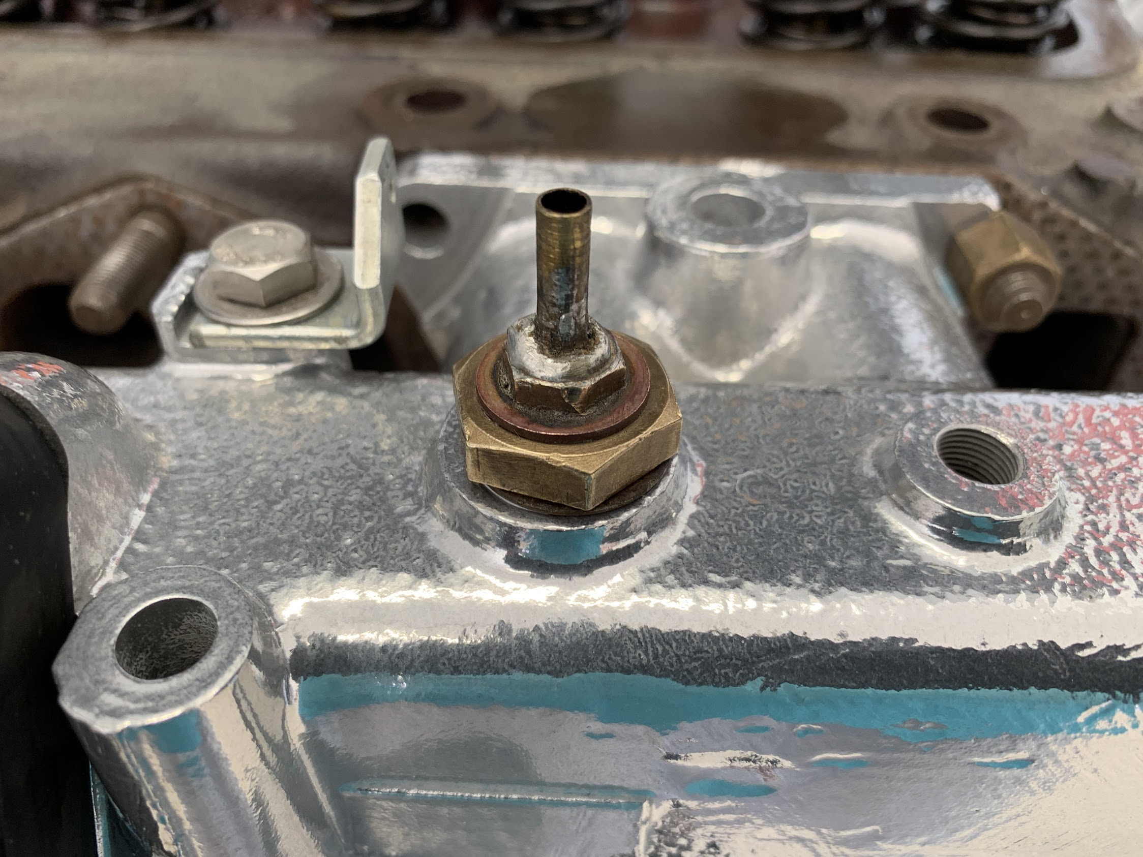
Vacuum Fitting for Cruise Control Installed
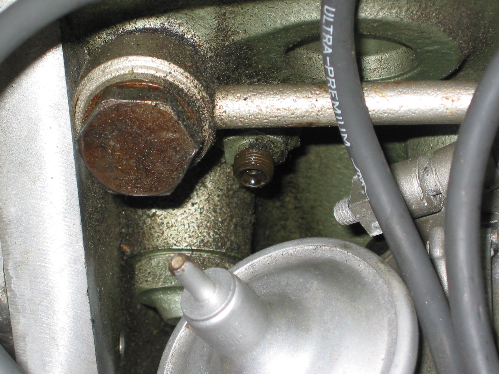
And, then replaced the rear vacuum port plug that screws into the threaded hole in the manifold.
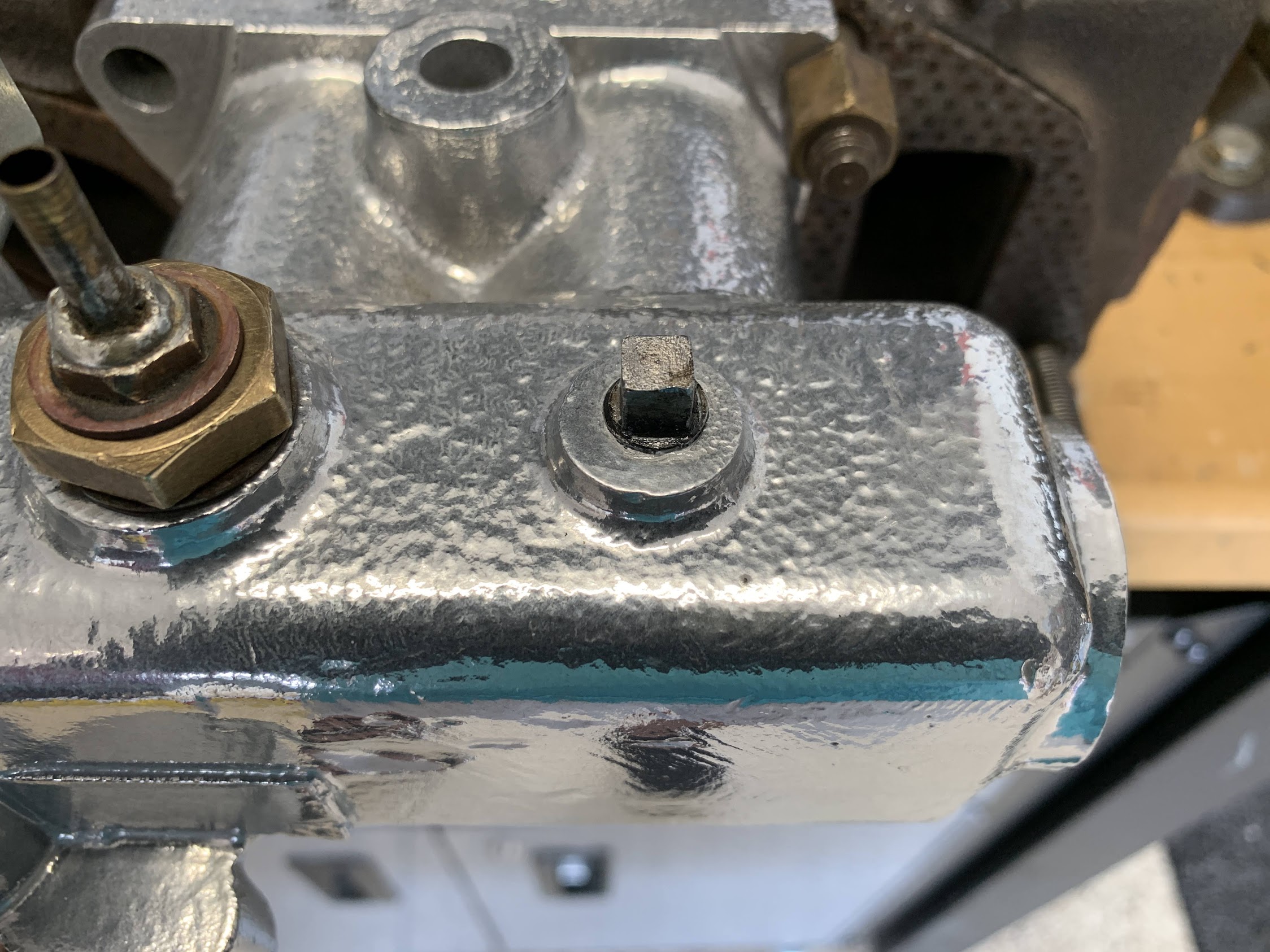
Rear Vacuum Port Threaded Plug
I then transfered the two 5/16 inch bolts that go through the intake manifold and originally mounted to the exhaust manifolds. Since my car uses exhaust headers these mounting points or not used, so I simply install bolts and nuts into the car holes.
Unused Mounting Bolts to Original Exhaust Manifold
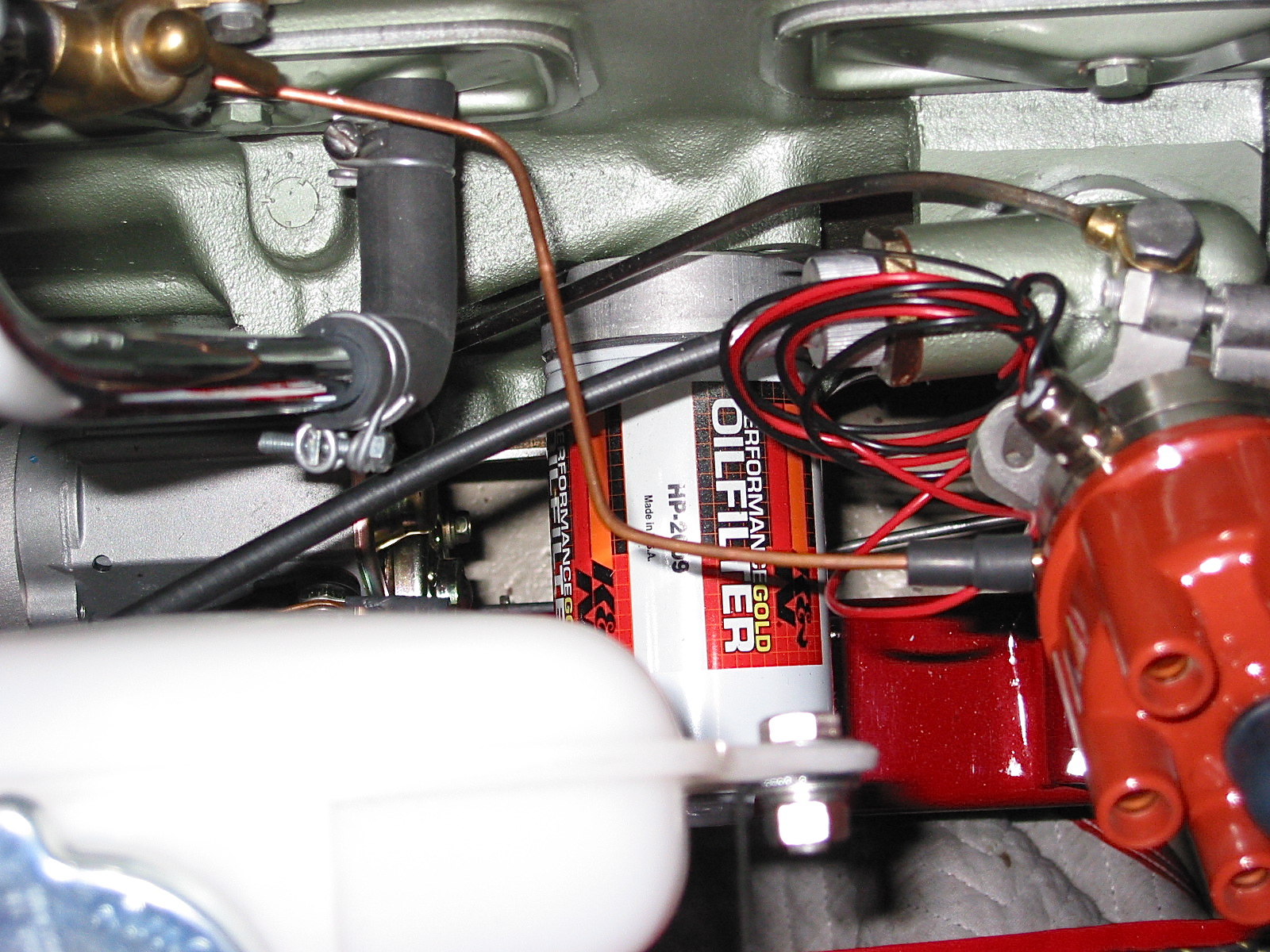
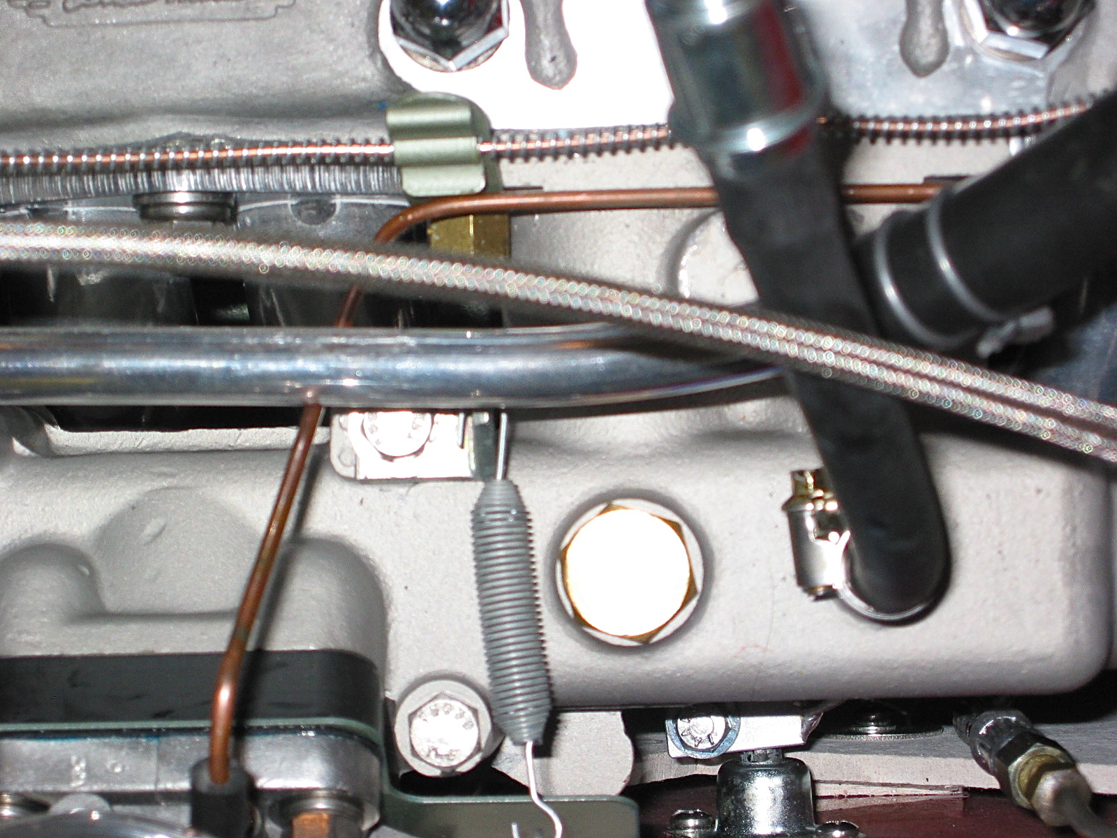
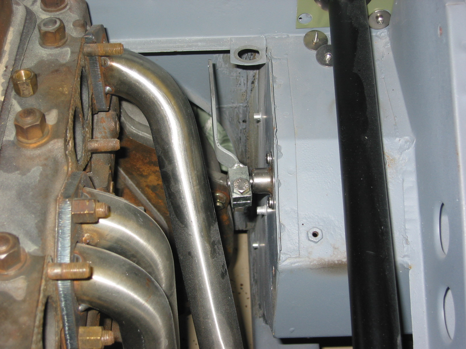
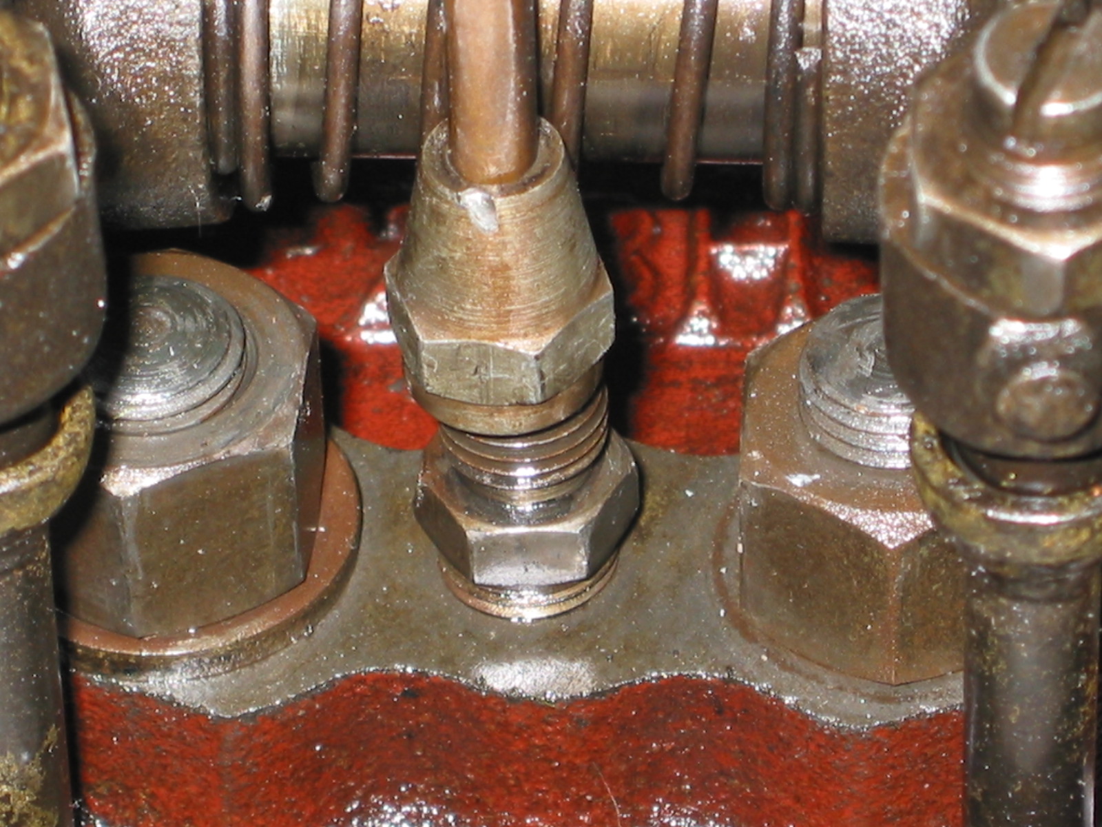
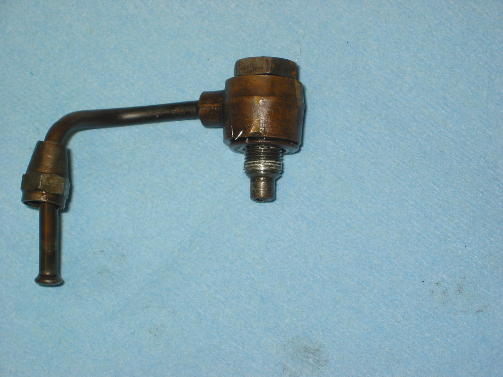
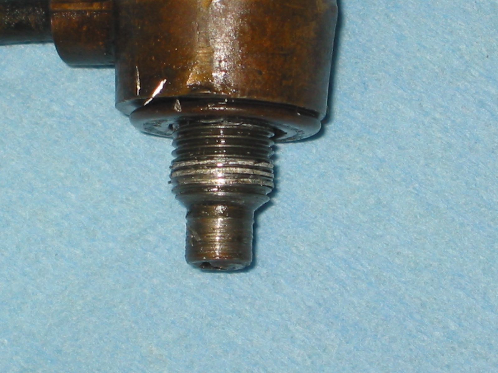
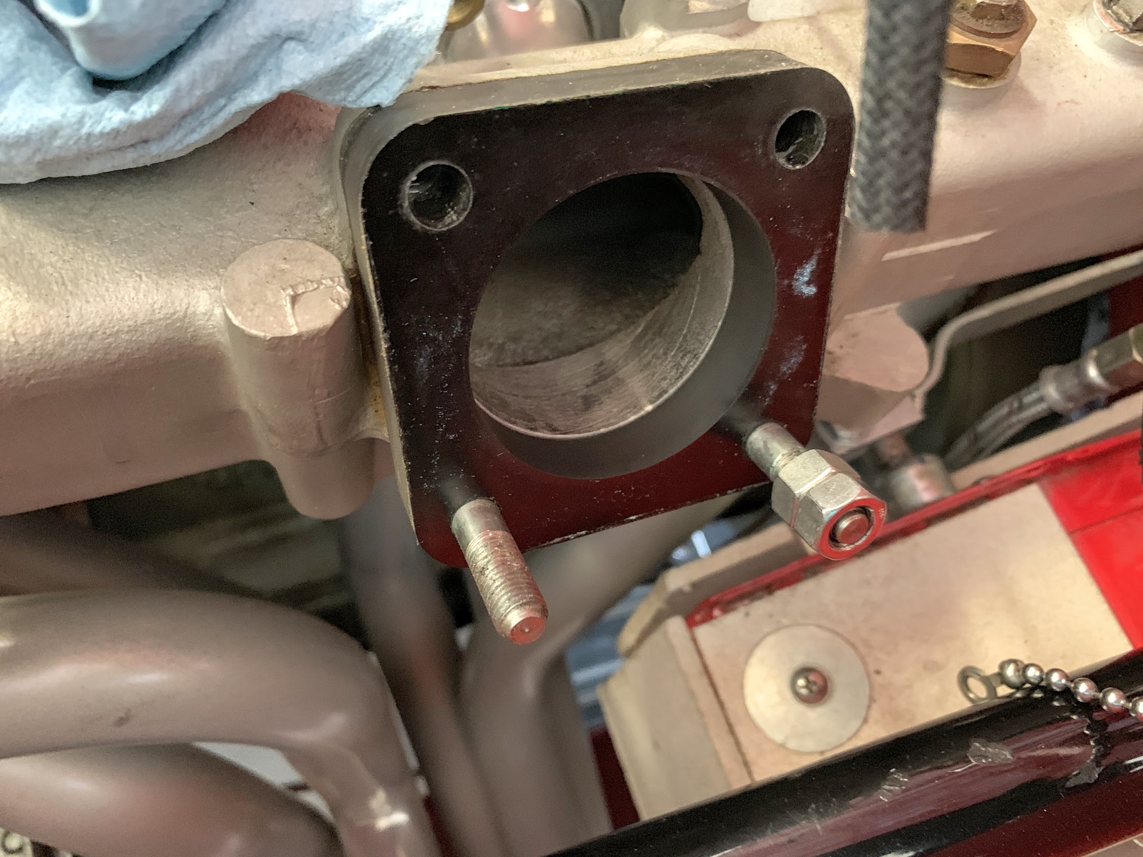
The original intake manifold design incorporates two fittings for fuel drain lines. I used both for the past ten years, but I decided to plug the rear drain hole with this rebuild. I really don’t know if there will be negative consequences to this or not. I did this because the rear drain line was extremely close to the rear header pipe. I just didn’t like that little copper pipe being so close – less that 1/8″ – from a hot exhaust pipe.
I am aware that some after market intake manifolds do not include the drain line fittings so I hope that this suggests that these drain lines may not be required? The image below shows the brass pipe fitting installed in the manifold.
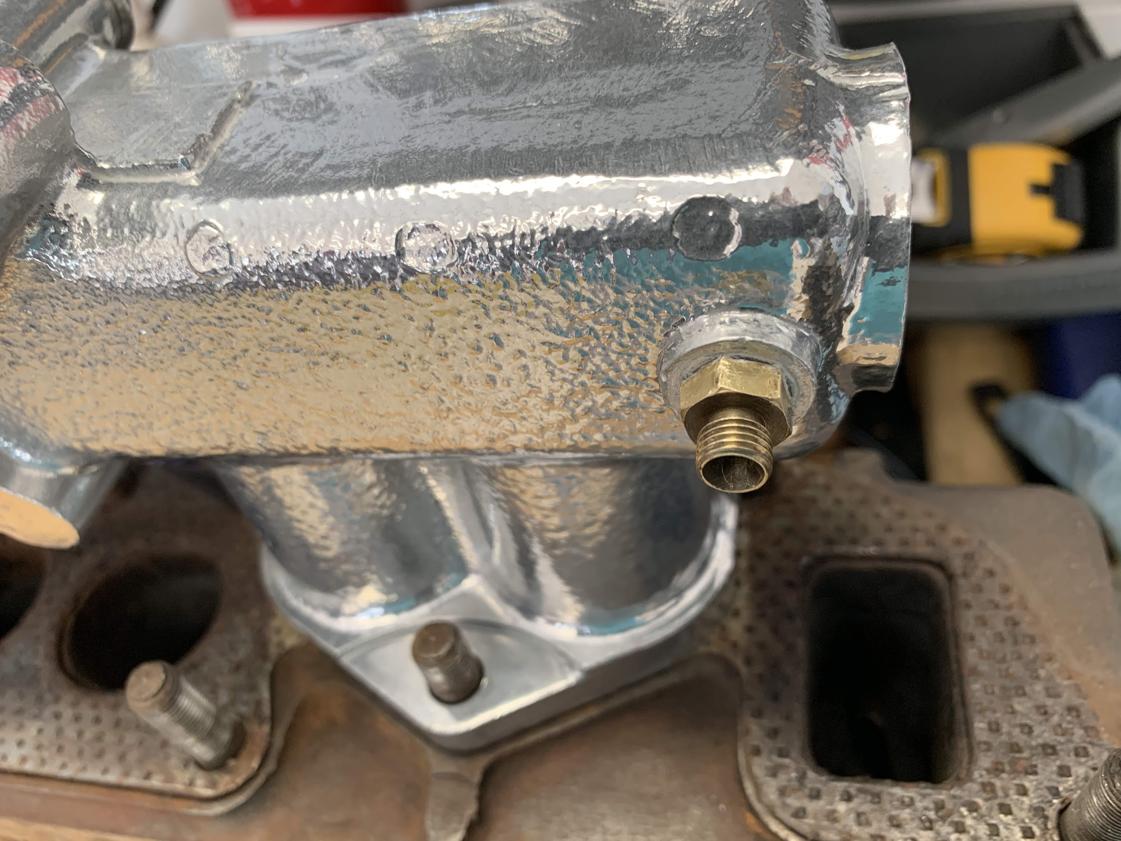
Intake Manifold Drain Fitting
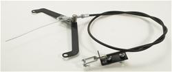
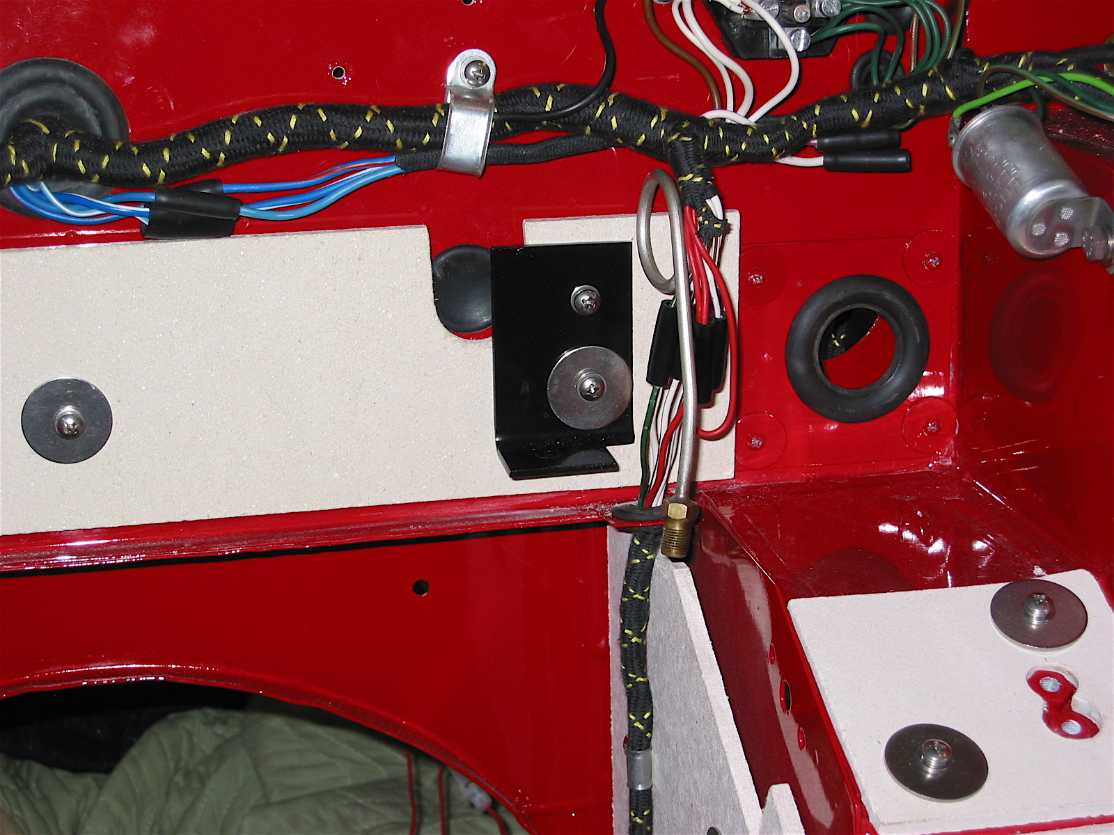
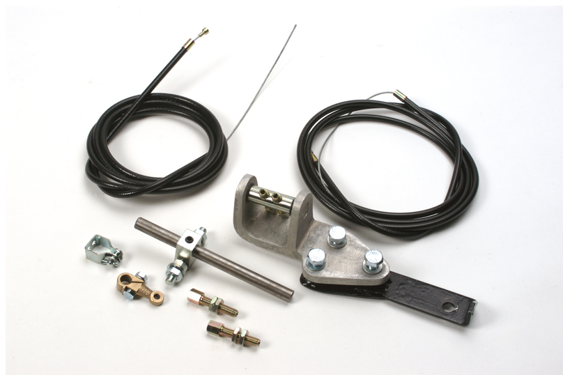
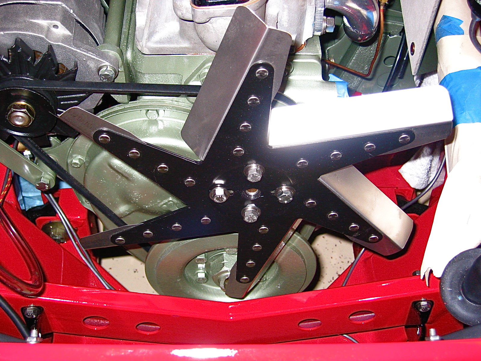
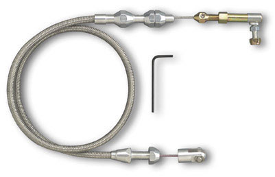
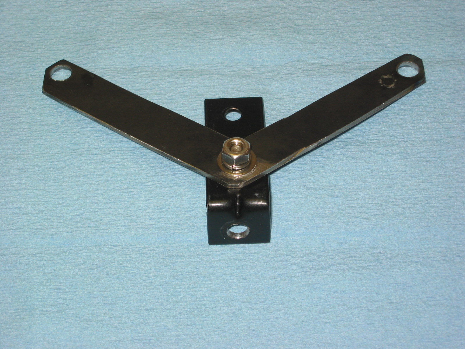
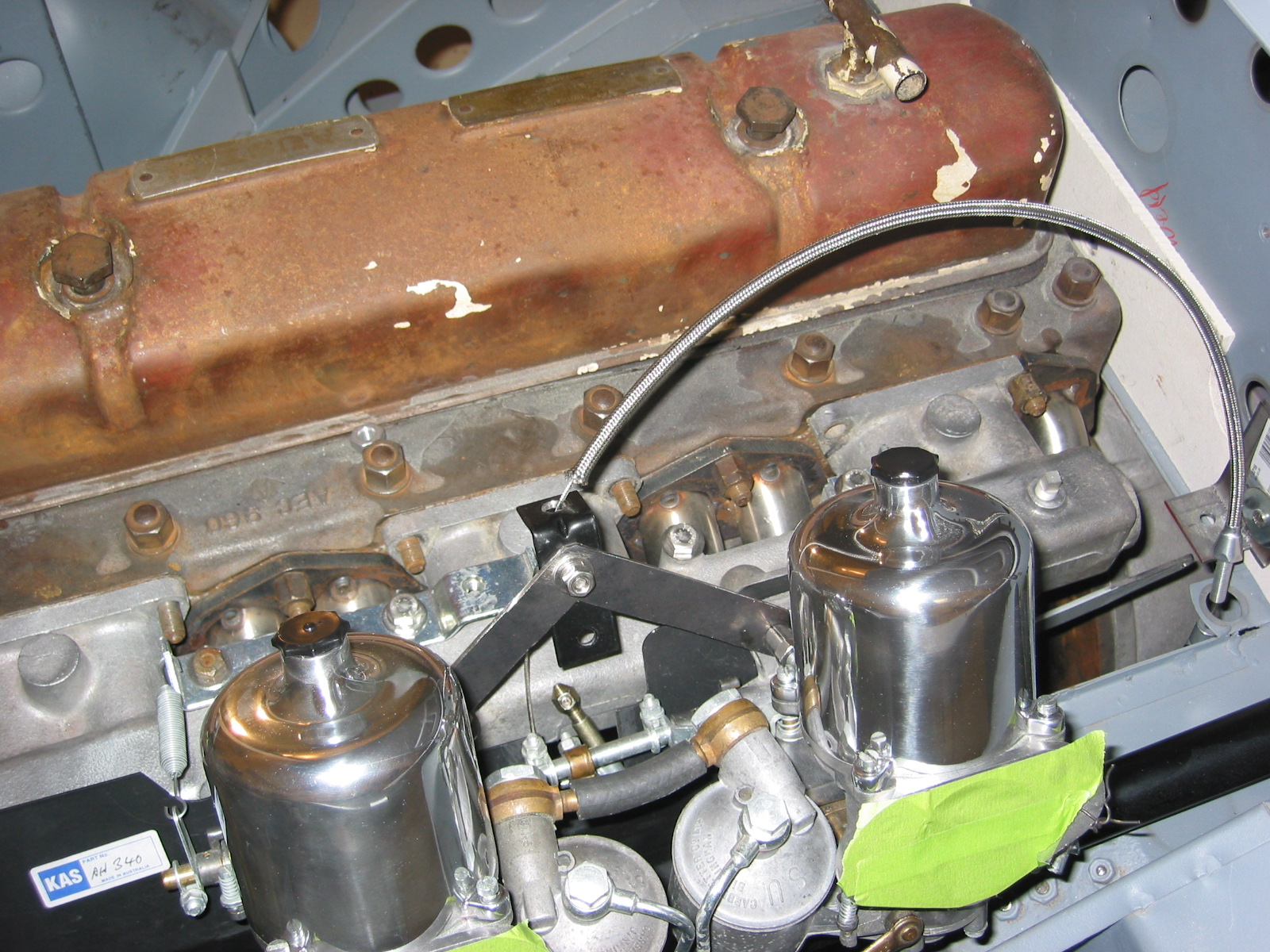
I then remounted the Dennis Welch Throttle Cable Bracket to the manifold.
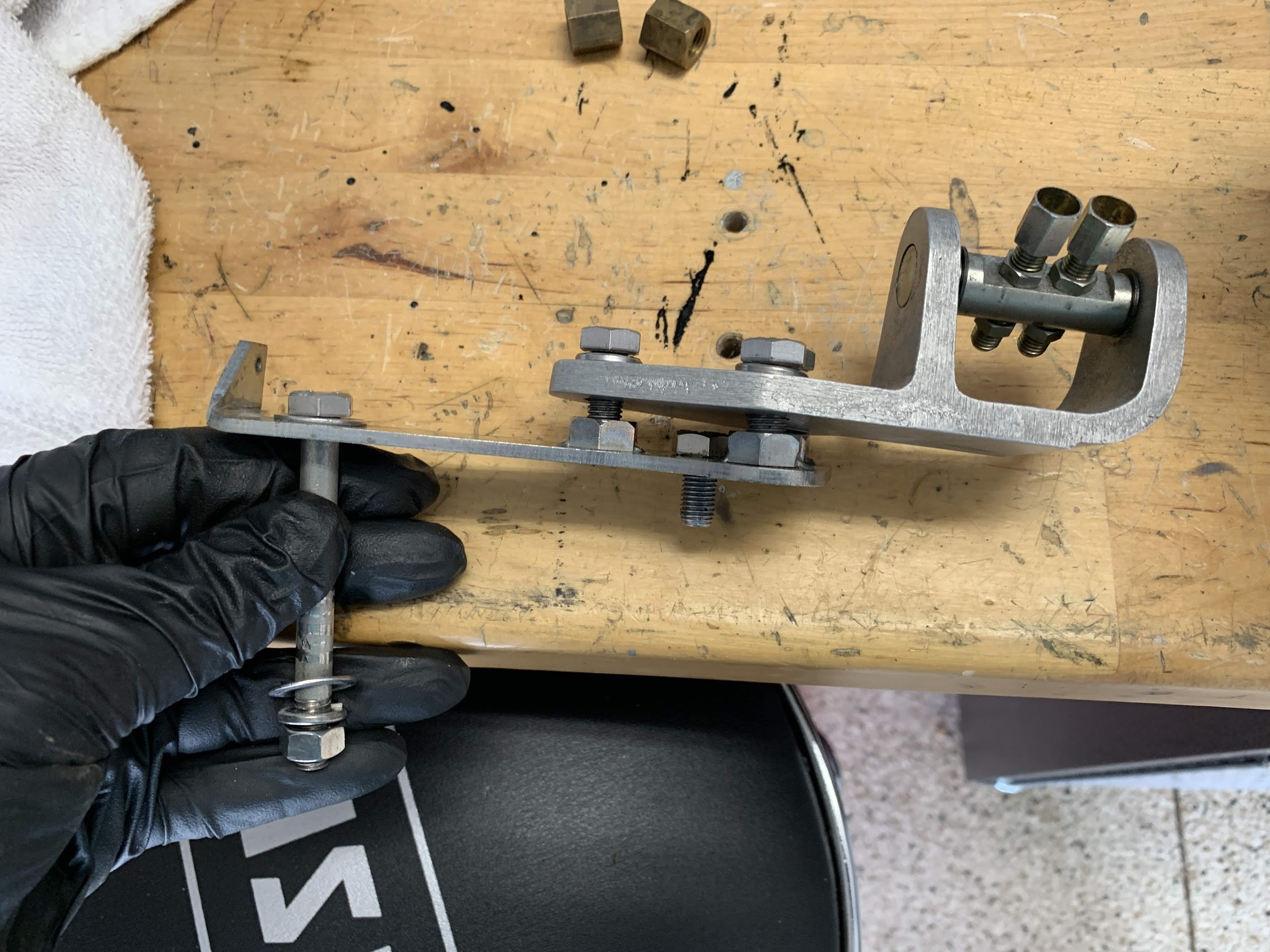
Dennis Welch Throttle Bracket
Dennis Welch Throttle bracket Installed
During some down time in this process I cleaned up the heat shield and repainted it.
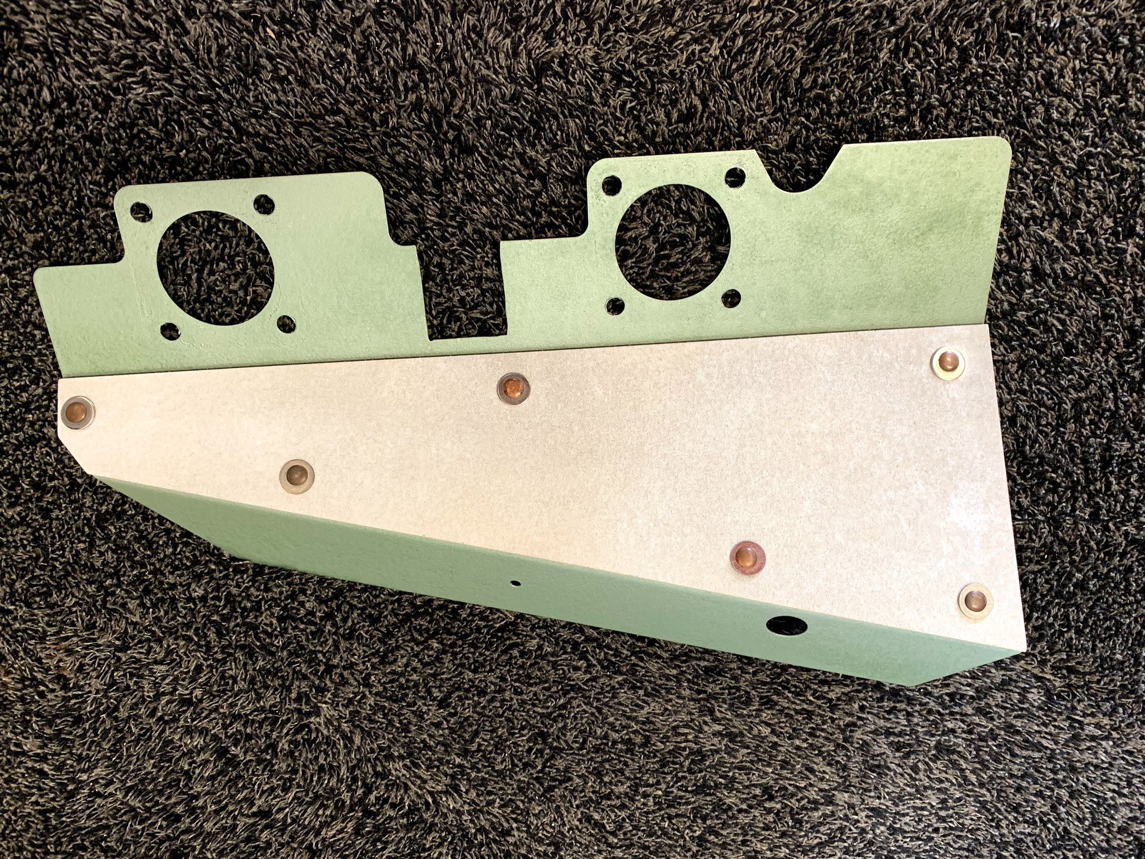
Refurbished Carb Heat Shield
I then put two new gaskets on each of the inlets in the manifold for the mounting of the heat shield.
Heat Shield Gaskets Installed on Intake Manifold
I then mounted the heat shield and added two more gaskets for the carburetors.
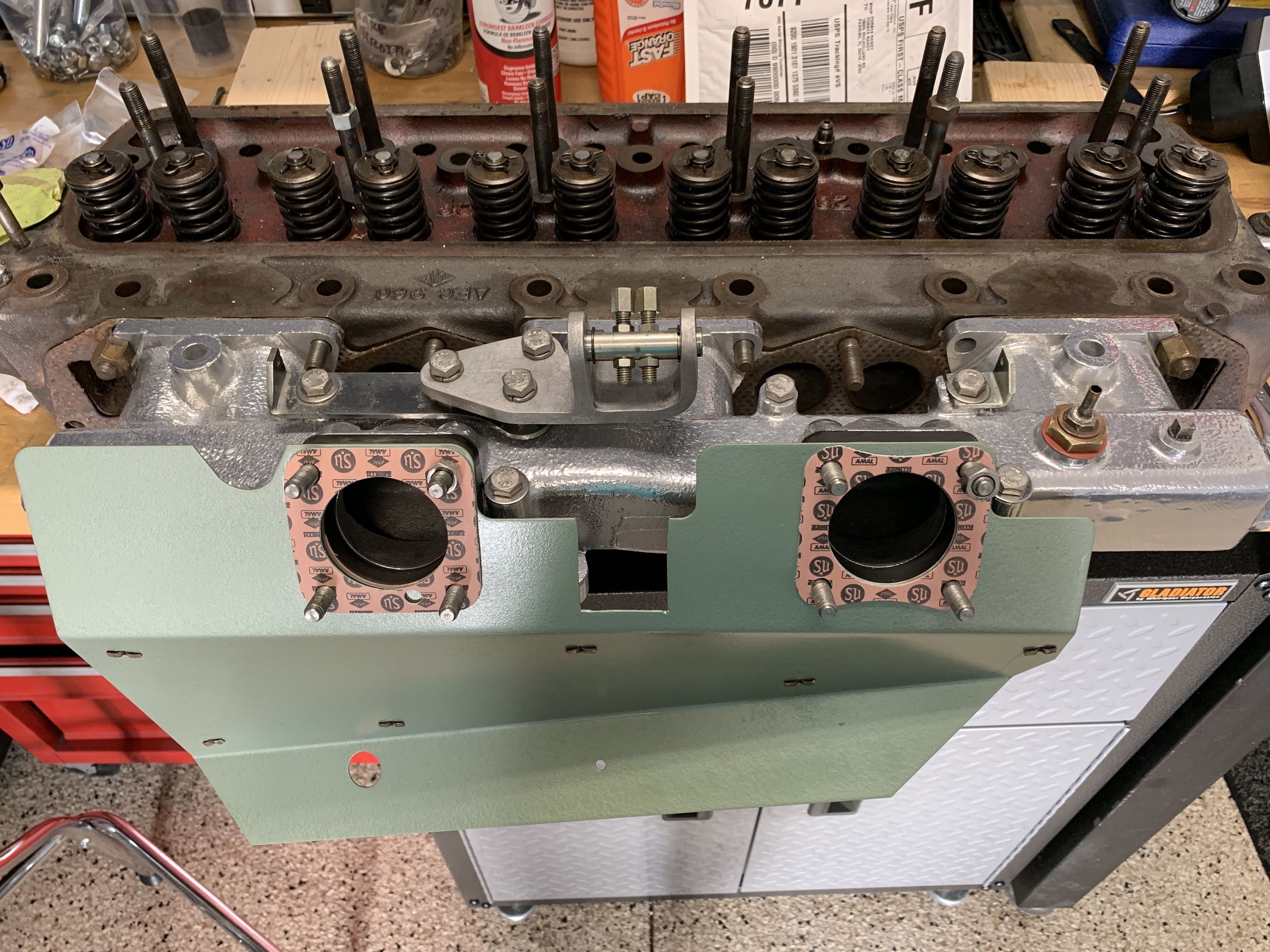
Heat Shield Gaskets to Carbs
At this point, I was ready to install the rebuilt carburetors to be described in the next post.