October 27, 2006
Jeremy’s Rotisseri
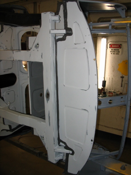
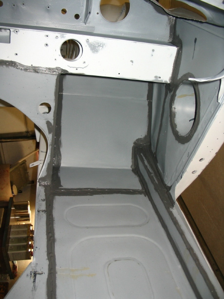
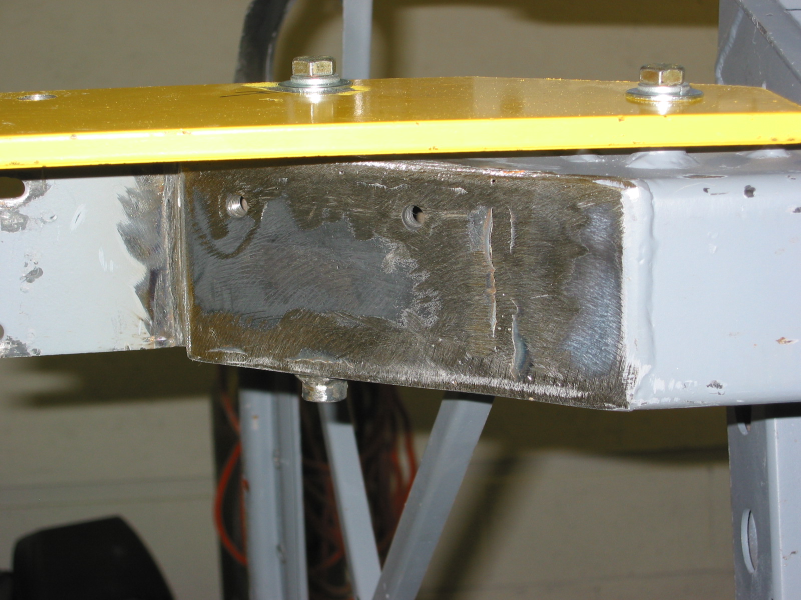
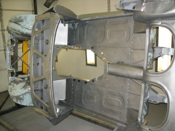
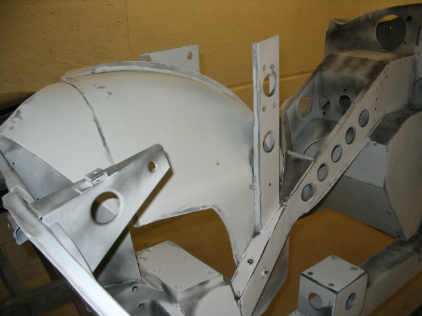
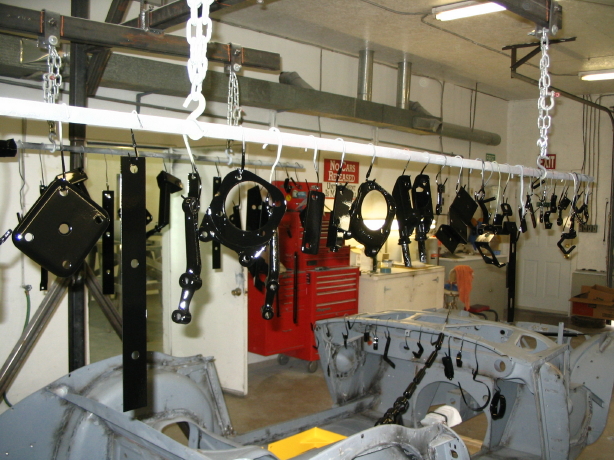
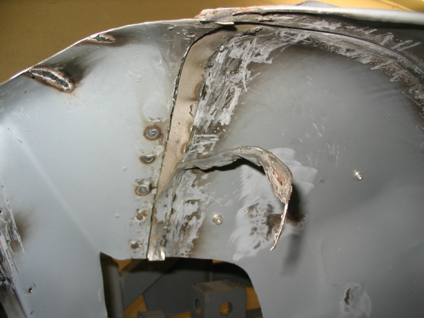
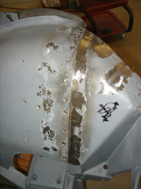
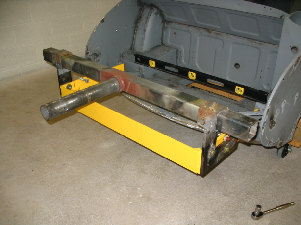
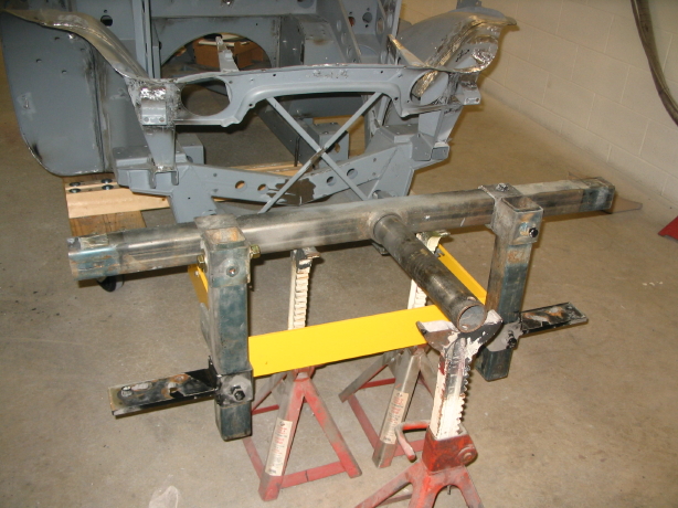
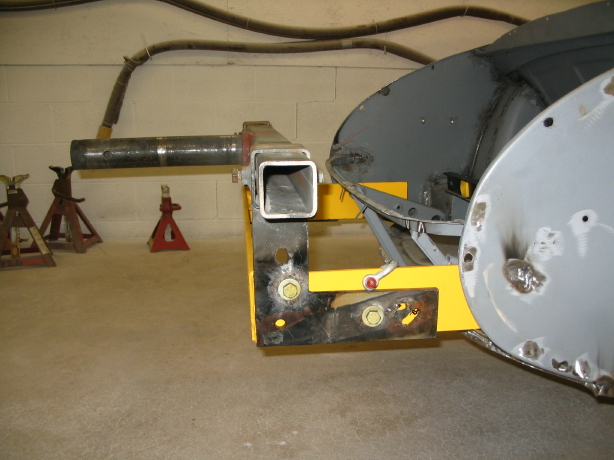
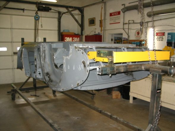
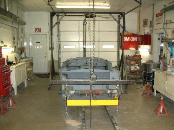
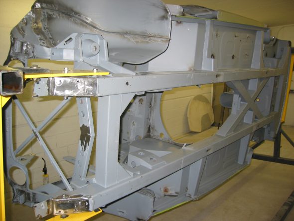
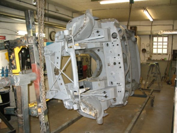
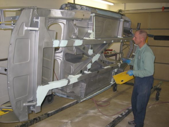
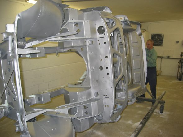
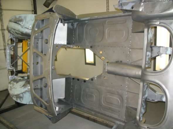
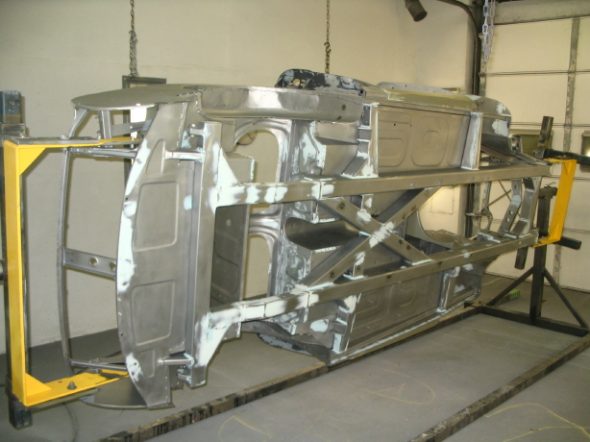
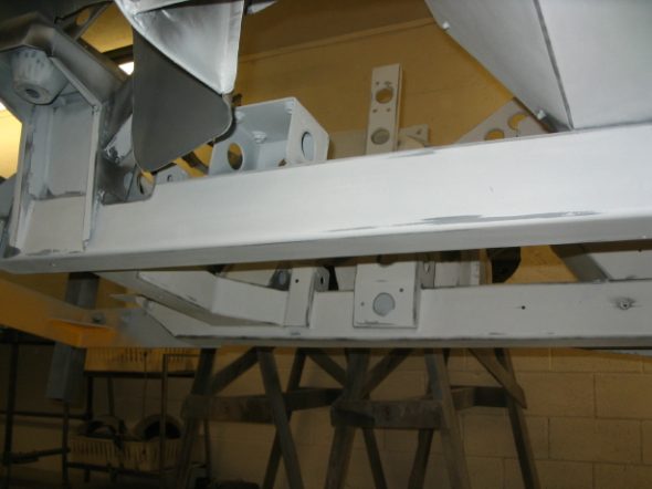
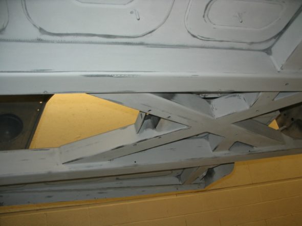
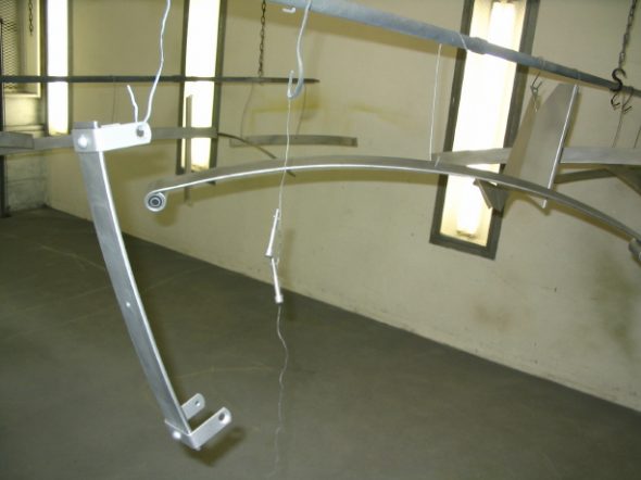
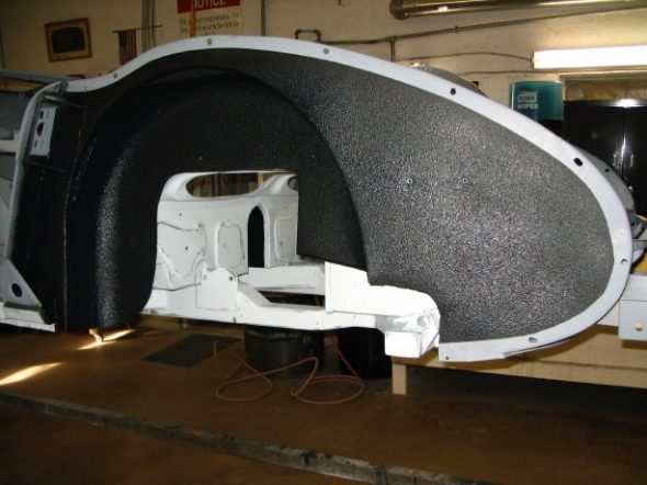
More Rotisseri Images – The rotisseri really does make working on the underside of the frame so much easier. These are a few additional images of the assembly at work.
rotisseri 7
rotisseri 6
Rotisseri 9
rotisseri 1

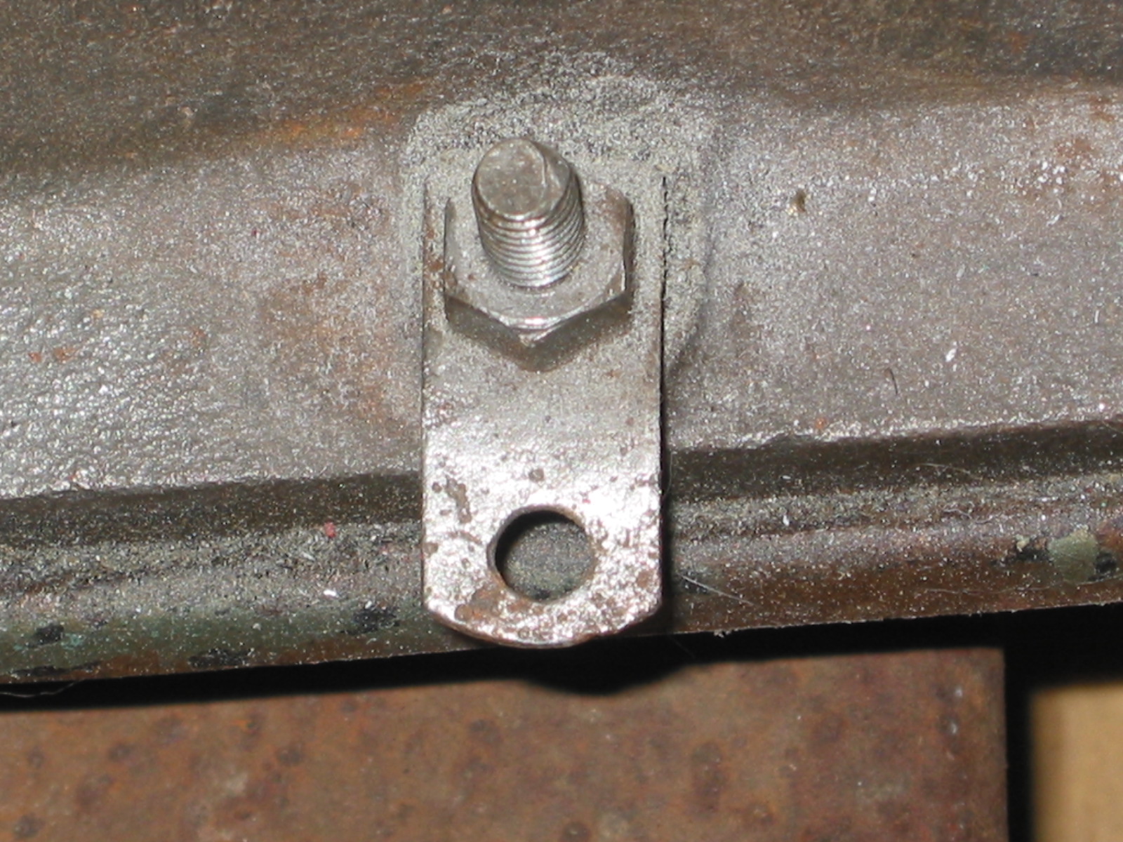
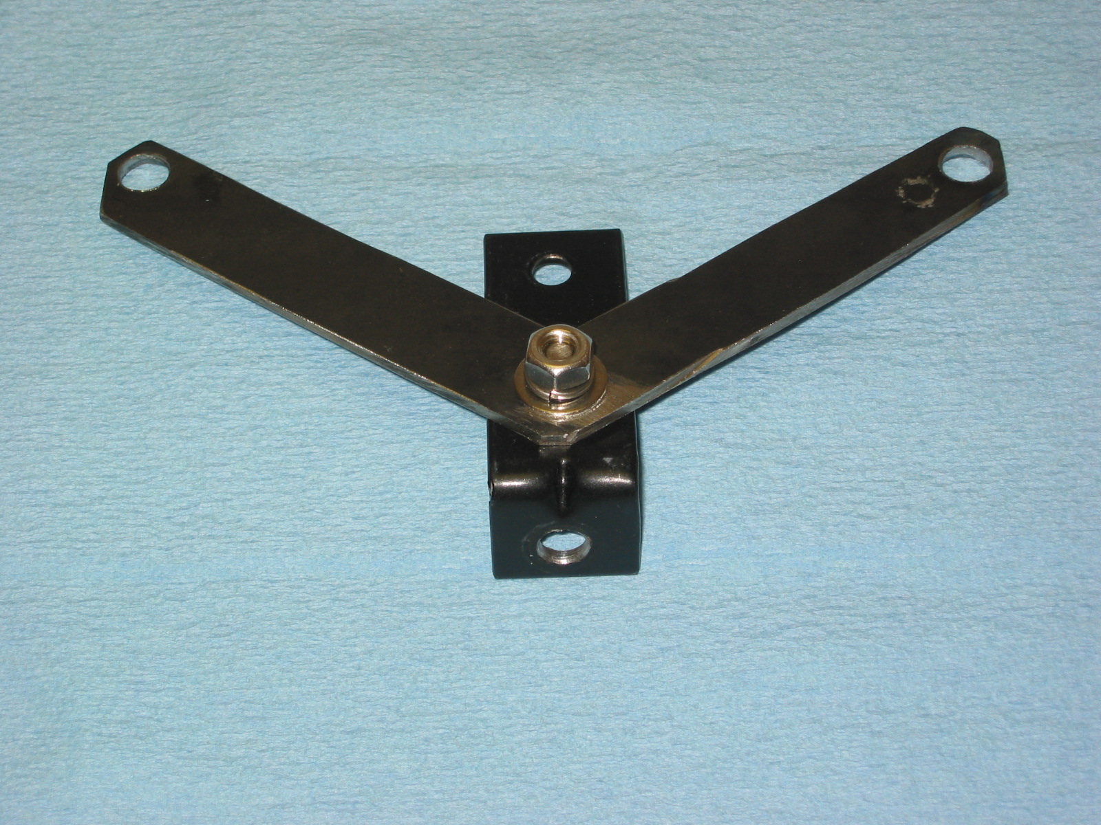
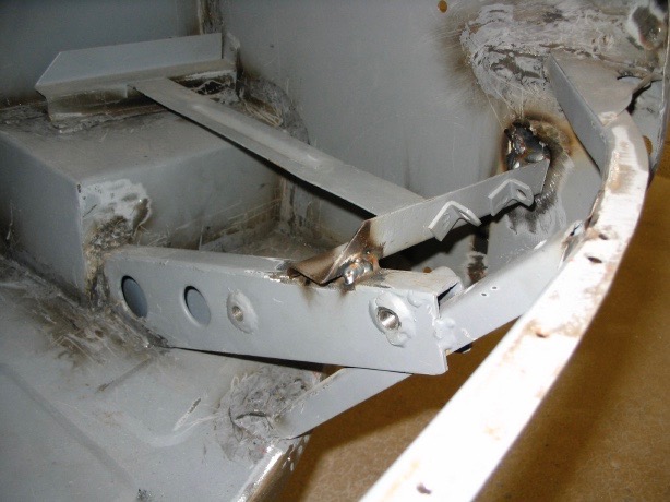
anti-sway bar bracket
November 7, 2006
Jeremy’s Bodywork
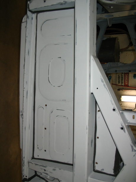
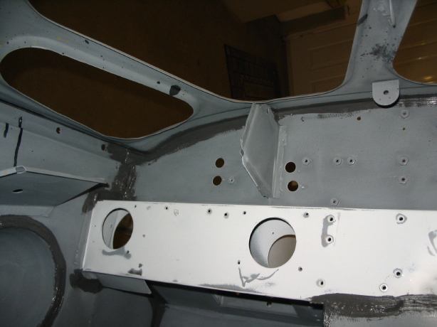
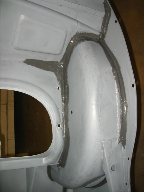
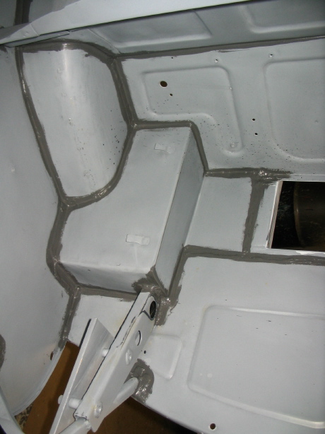
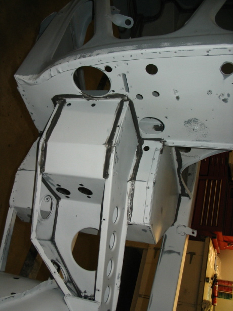
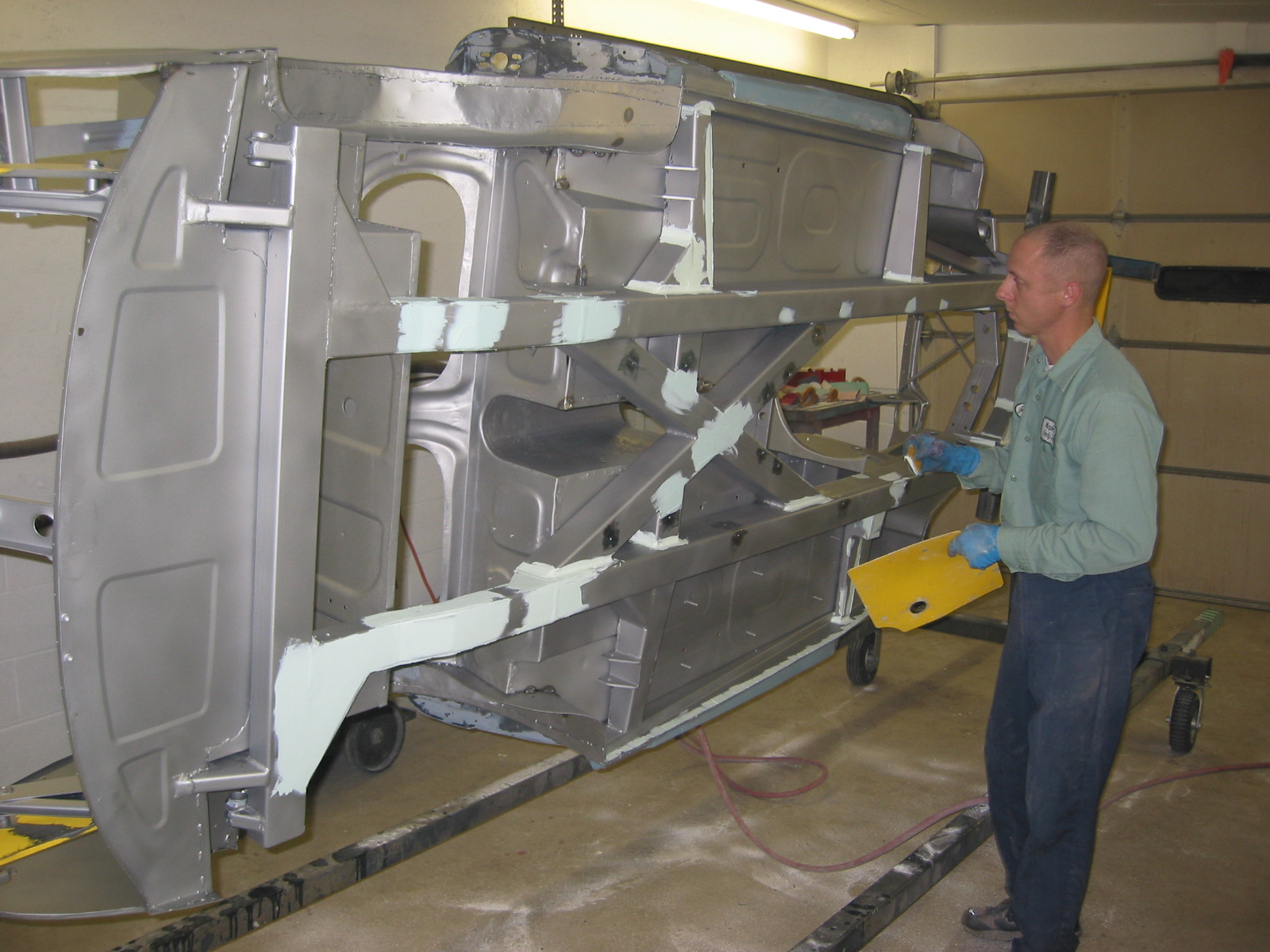
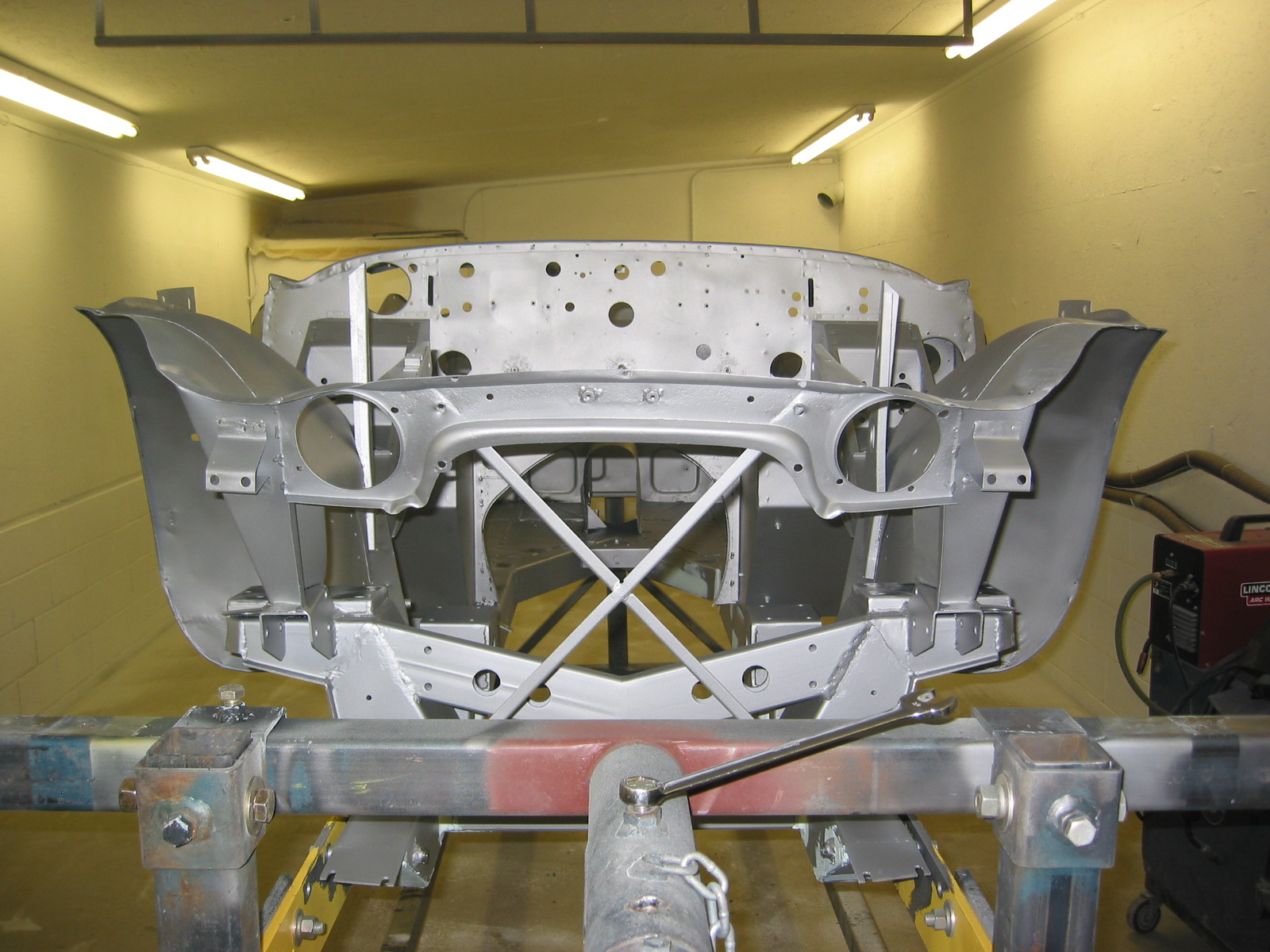
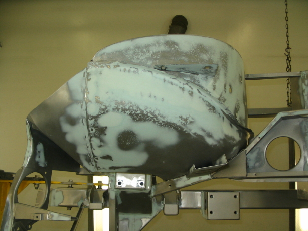
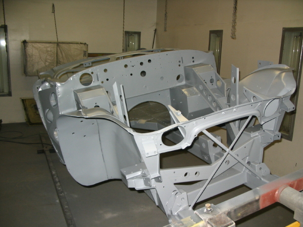
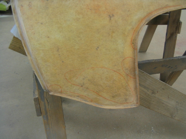
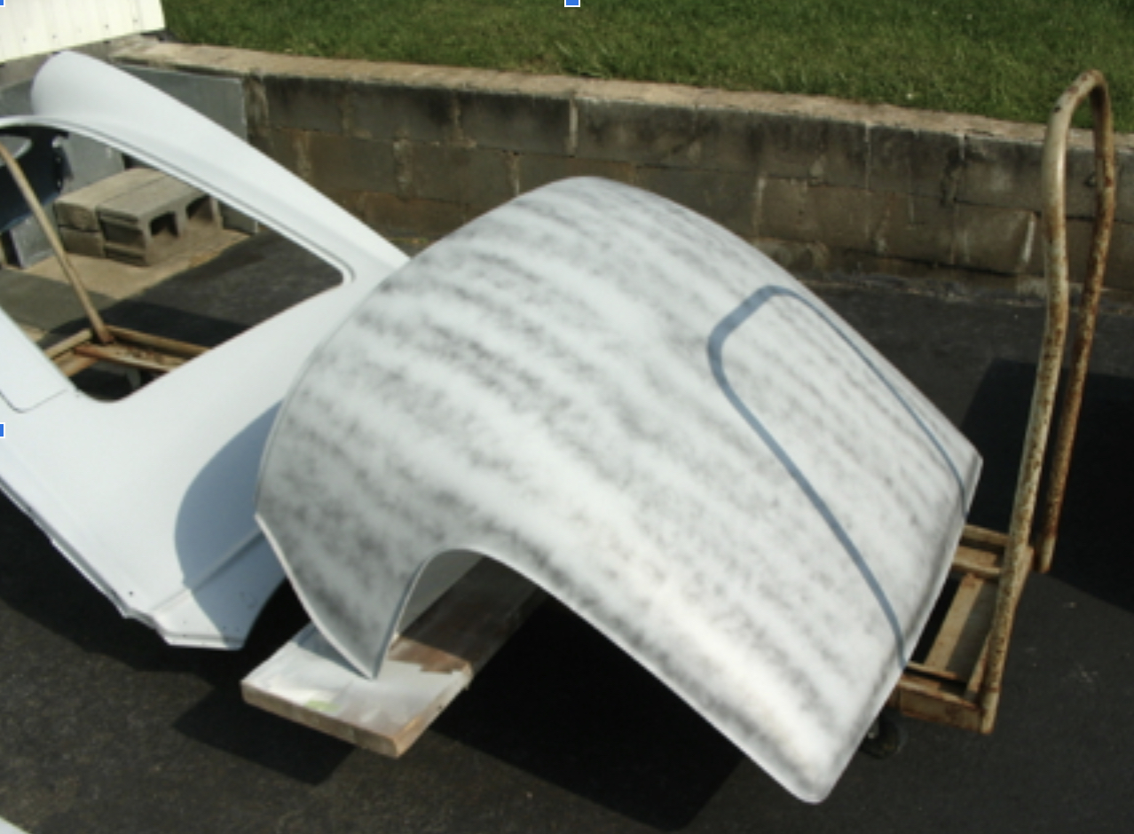
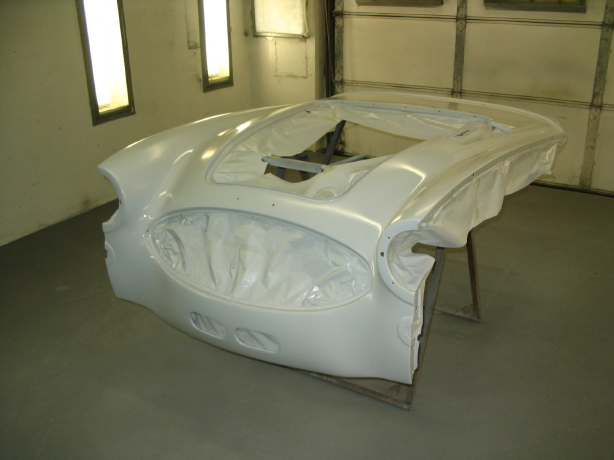
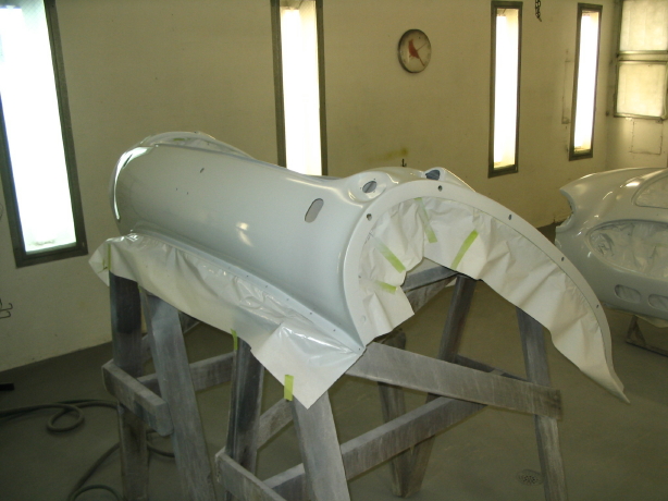
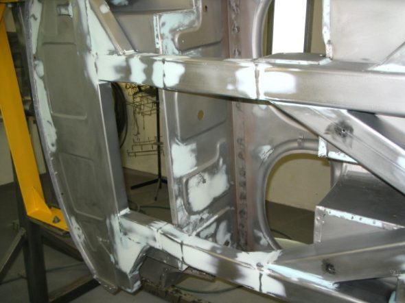
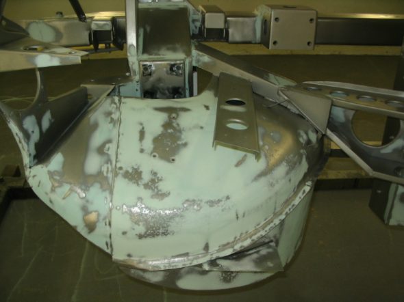
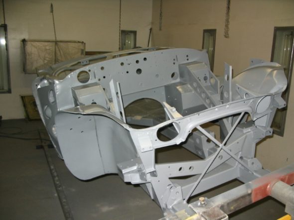
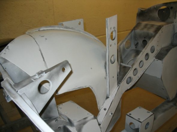
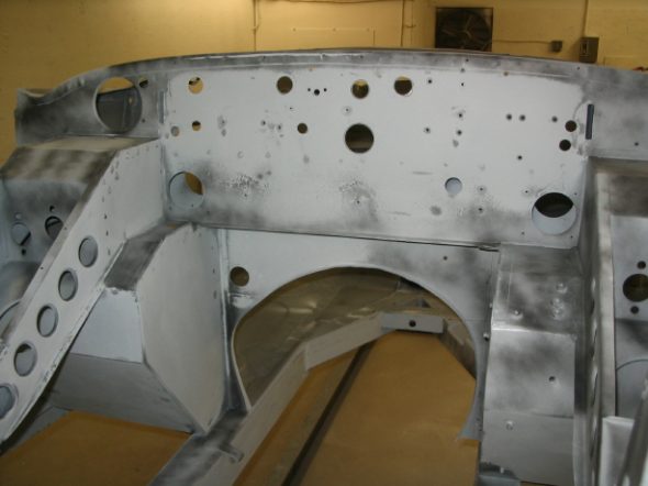
Jeremy has continued to work hard on the final work on the frame/tub. He has done a very nice job with the judicious use of filler to give a nice finished appearance to the frame as if it was the body! Pitting on the outside of the kick panels and on the underbonnet inner fenders just looks great.
Frame blasted clean 1
Frame blasted clean 9

Frame blasted clean 10
fill primer 3
frame bodywork
frame bodywork 3

frame bodywork 2
frame bodywork 4
frame epoxy primer 1

fill primer 4
Final sanding 1
Final sanding 2
Final sanding 3
Final sanding 4
November 12, 2006
Engine Rebuilding
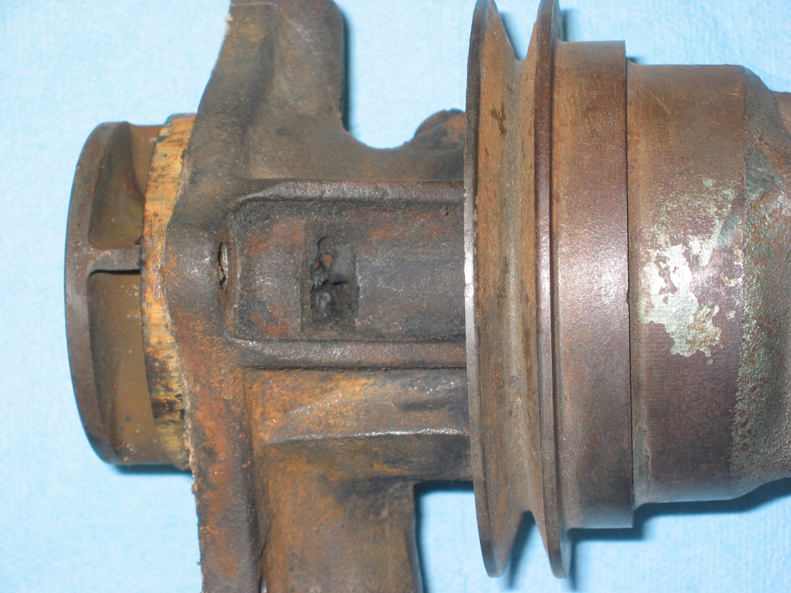
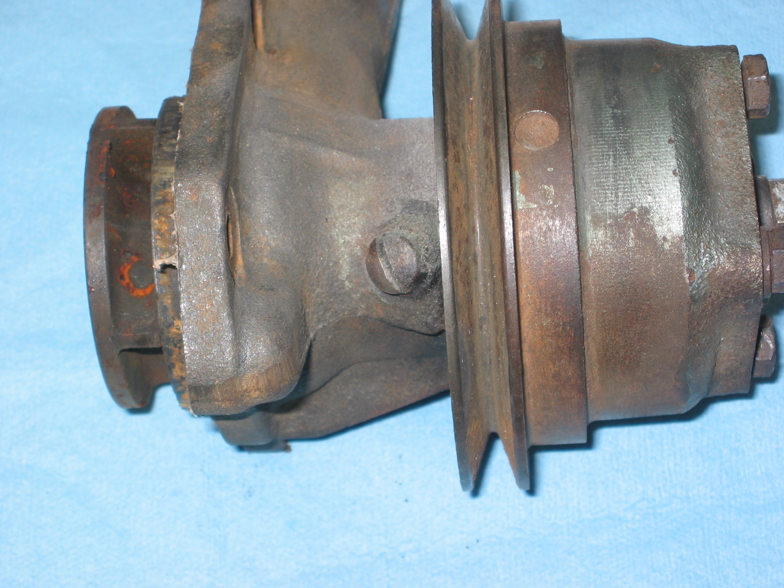
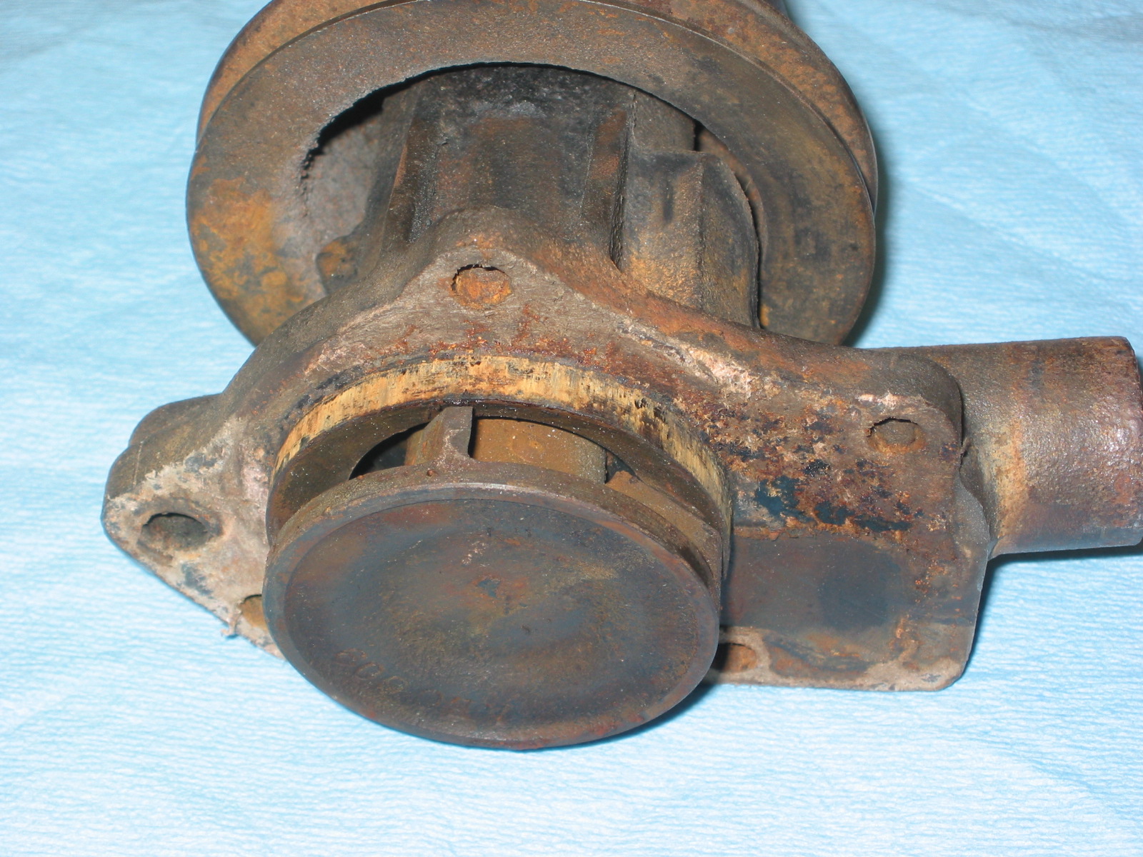
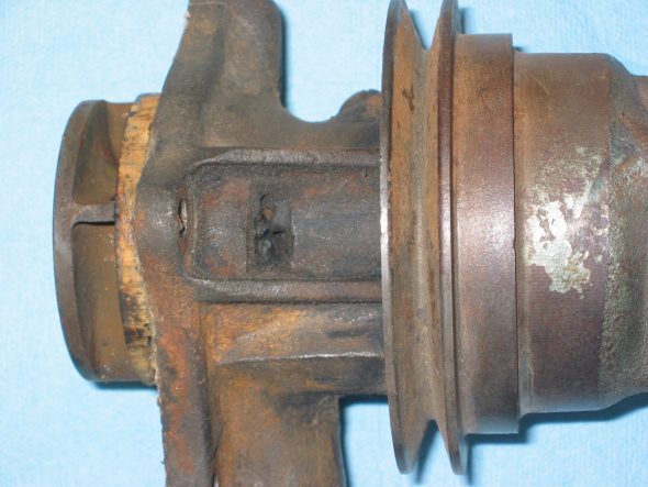
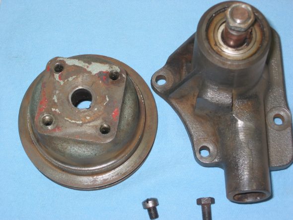
Water Pump – Although Jack Harper will be doing the engine rebuild, there are some items that I can take care of before I take the motor to him. I already sent the rocker arm assembly out for rebuild, and today I queried the internet healey list about their thoughts on the water pump. Was I better to rebuild my own or purchase an after market replacement? Those whose opinions I have come to count on recommended rebuilding my own and perhaps purchasing a new one to have as a spare. Bill Bolton, Peter Caldwell and Joe Curto were suggested as possible rebuilders. I had experience with all three but decided to call Peter since his lever arm Armstrong shock rebuilds will be on my car and because so many rave about the quality of his work. He indicated that his company didn’t “officially” do water pump rebuilds, but they were getting ready to do a number of them and that I should send mine along His rebuild would be $75.00. I took mine off the motor – four nuts on studs and took the pully off the pump shaft. That required the use of the slide hammer, but was easily accomplished.
Water pump 1

Water pump 6
Water pump 8

Water pump 5
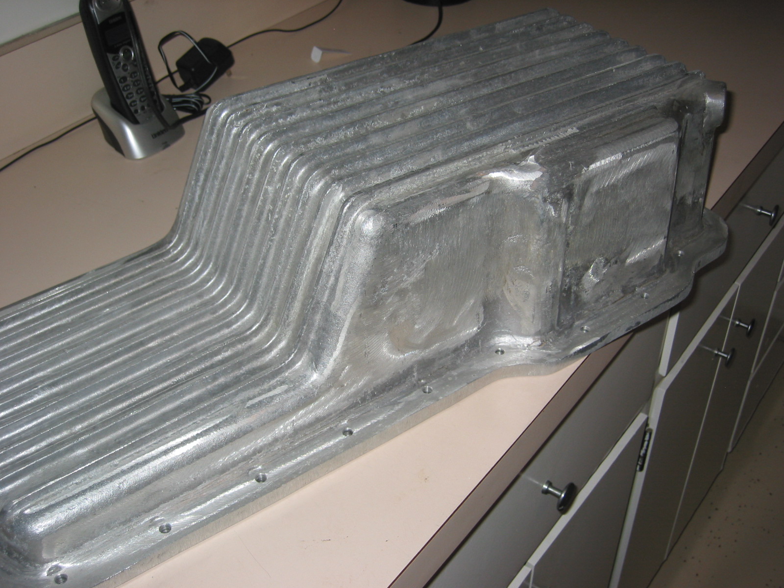
Aluminum Oil Sump – I ordered an aluminum oil sump from British Parts Northwest. After researching the sumps available from various suppliers. Others reported that the BPN sump did not require modification to the oil pump because it is a little deeper than the others. Of course, that also means it protrudes lower in the frame, but since my motor mounts are ¼” high I concluded that it would work best. Unfortunately, it arrived in pretty rouh shape with grinder marks on the exterior and some casting depressions. I sanded the body until most of the grinder marks were eliminated. Jeremy will glass bead blast and we will put a few coats of clear paint on it for protection.
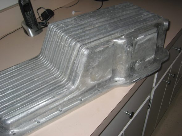
aluminum oil sump 2
November 24, 2006
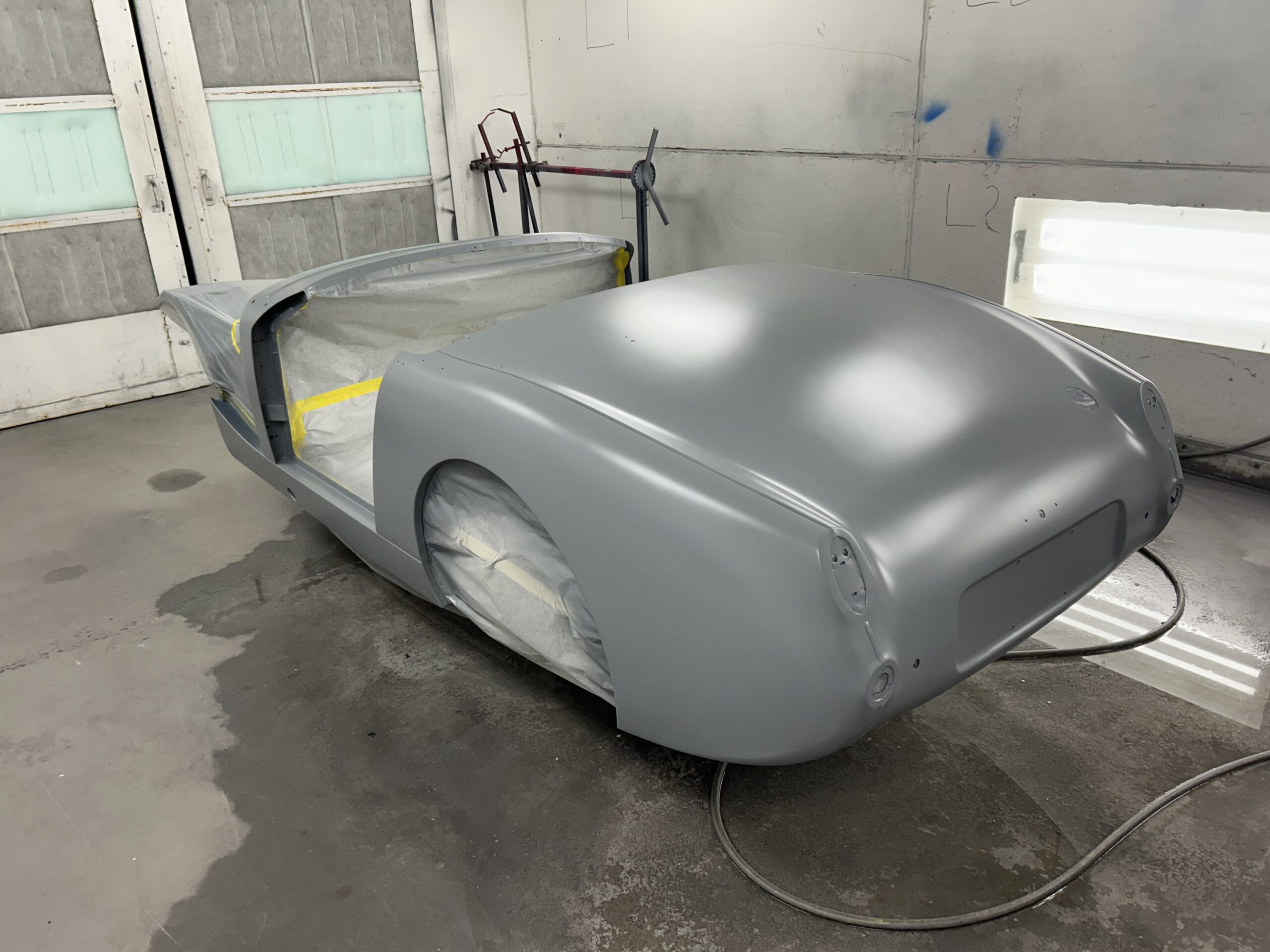
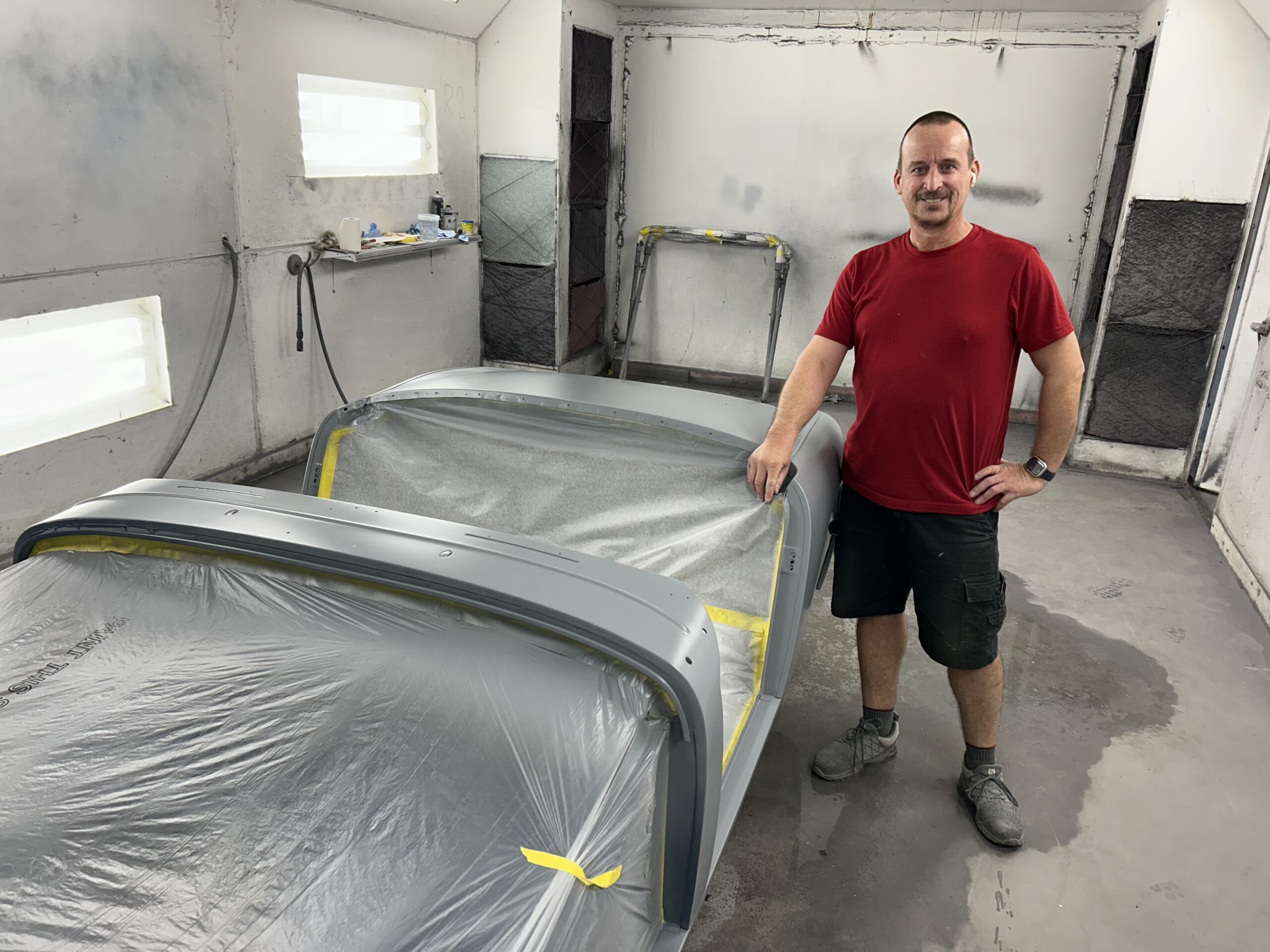
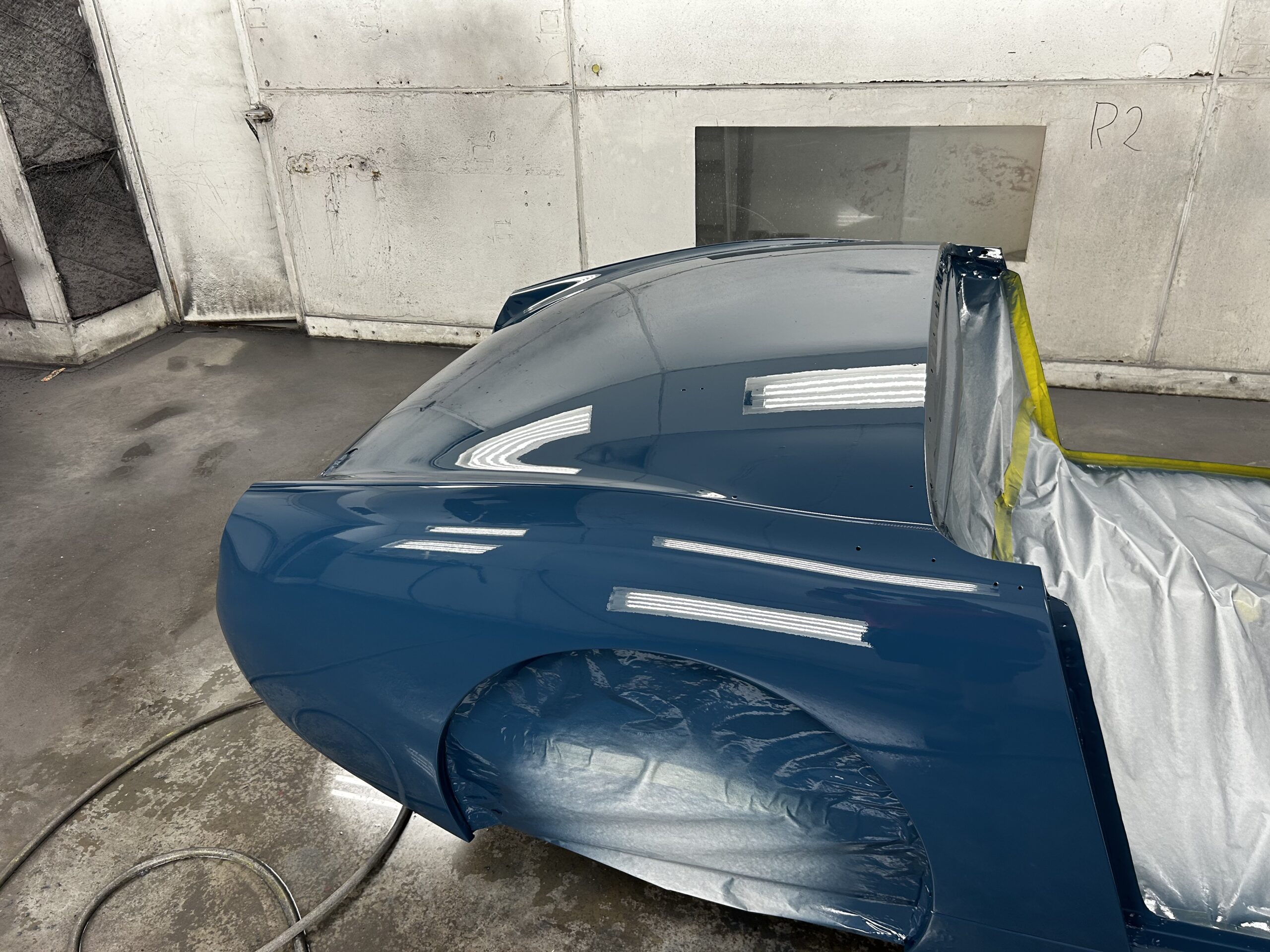
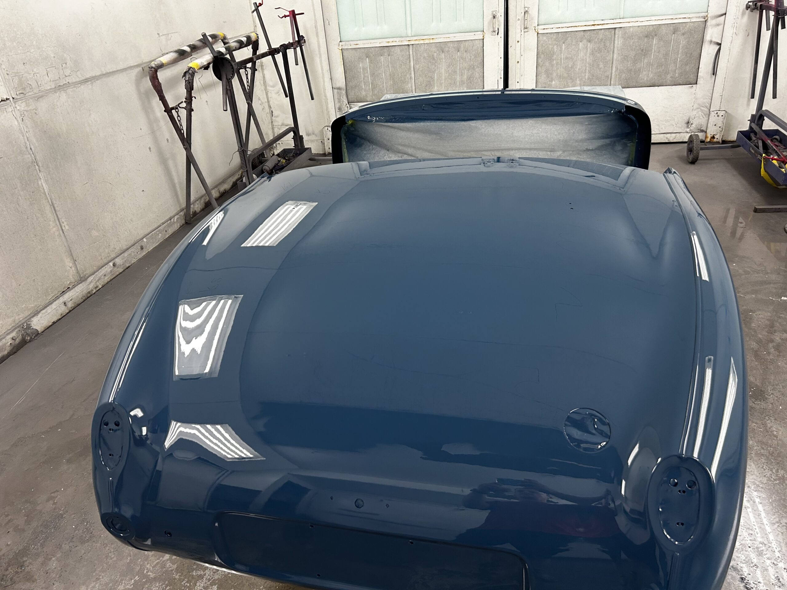
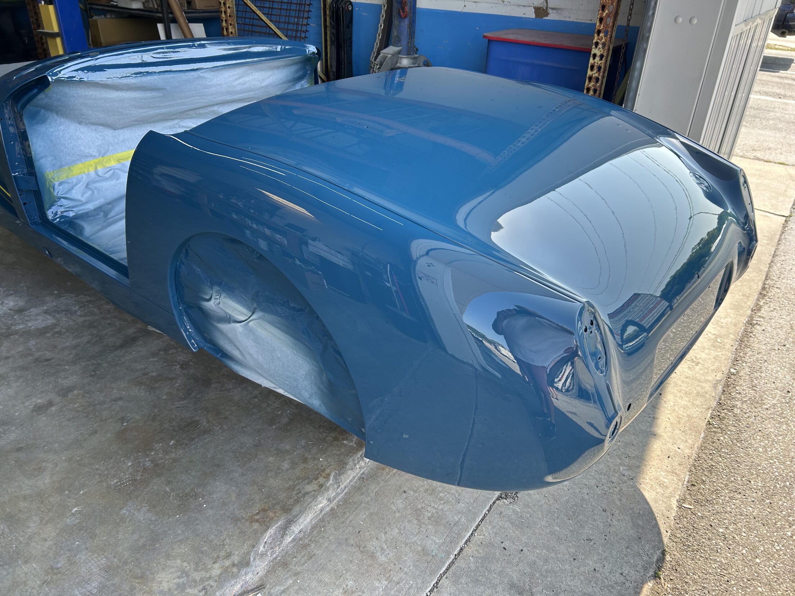
Jeremy’s Painting and Bodywork
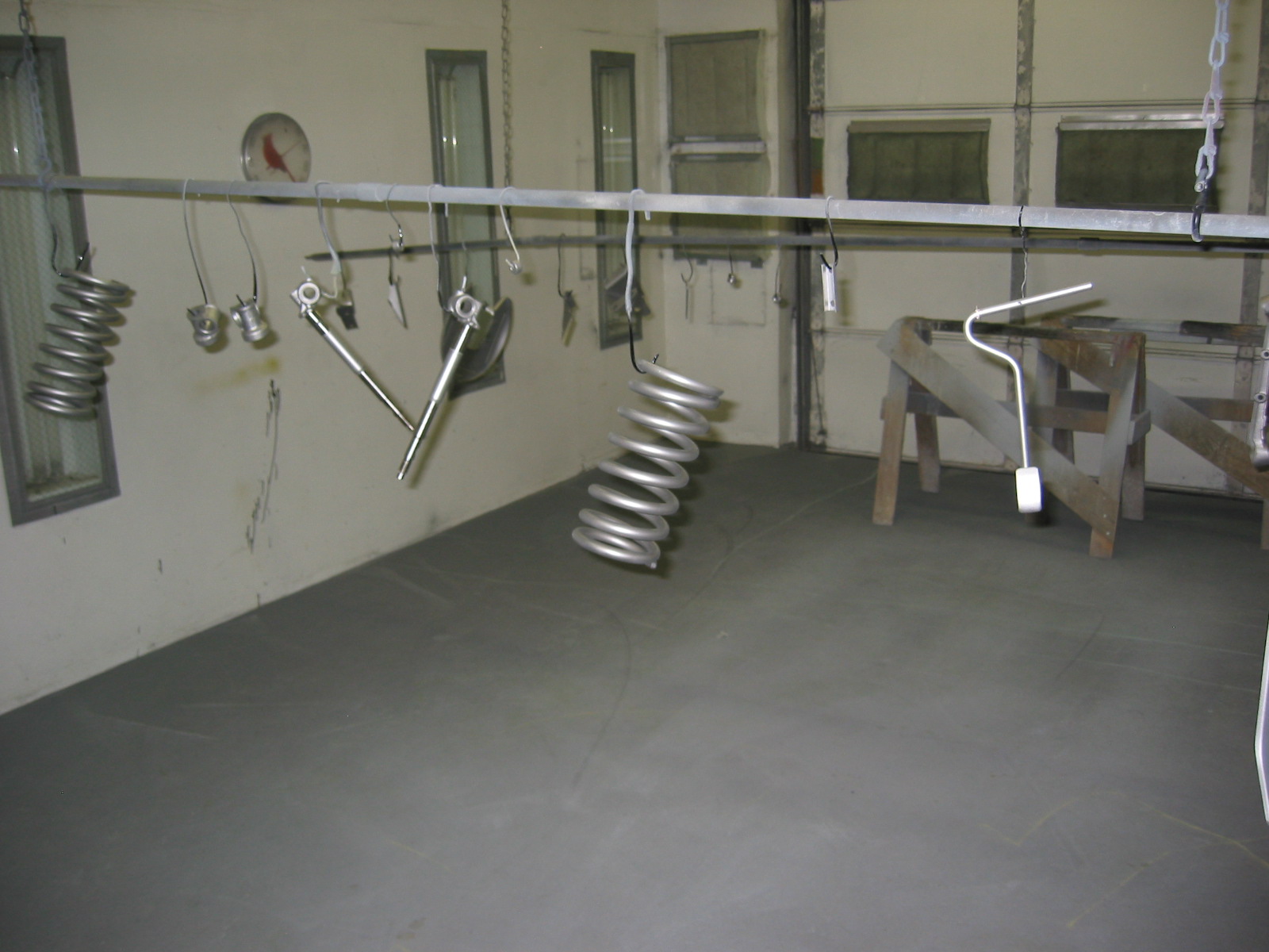
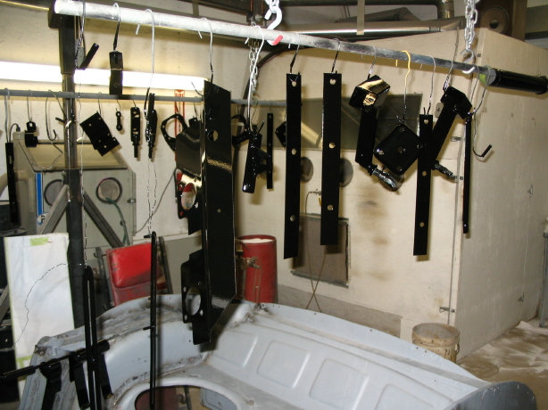
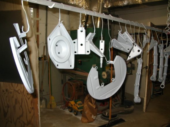
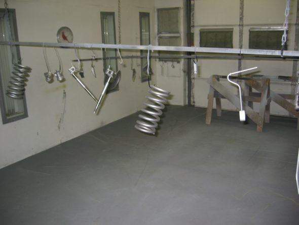
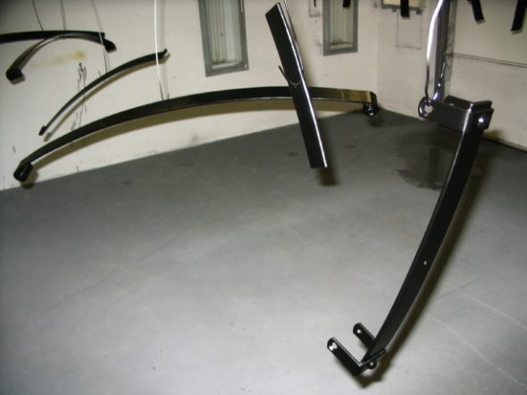
Suspension and other little bits – To take a break from sanding the frame, Jeremy turned again to finishing some of the smaller parts that are to be painted gloss black. The following images show some of the work.
small primed parts 2
media blasted parts 2
small parts black 1
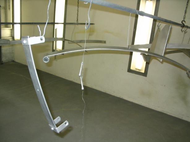
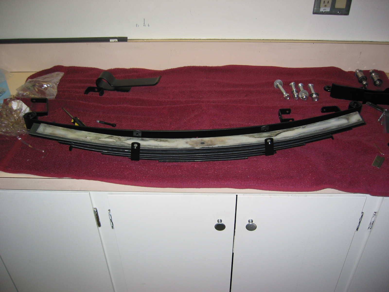
rear springs blasted 1
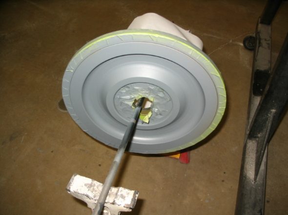
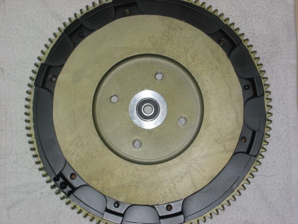
flywheel ready to paint
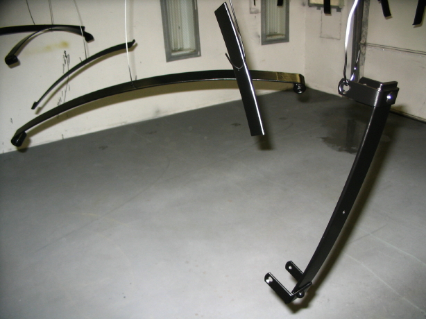
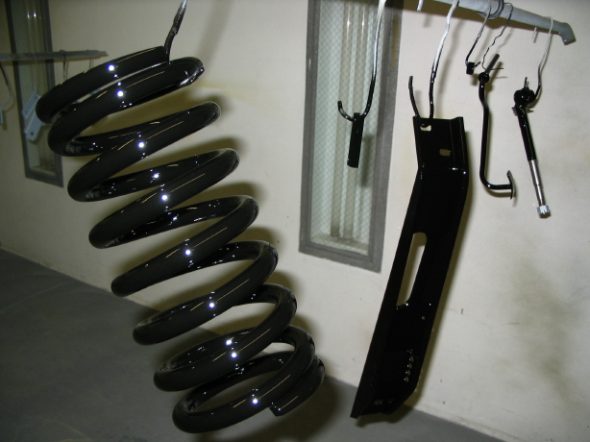
Rear Springs painted 1
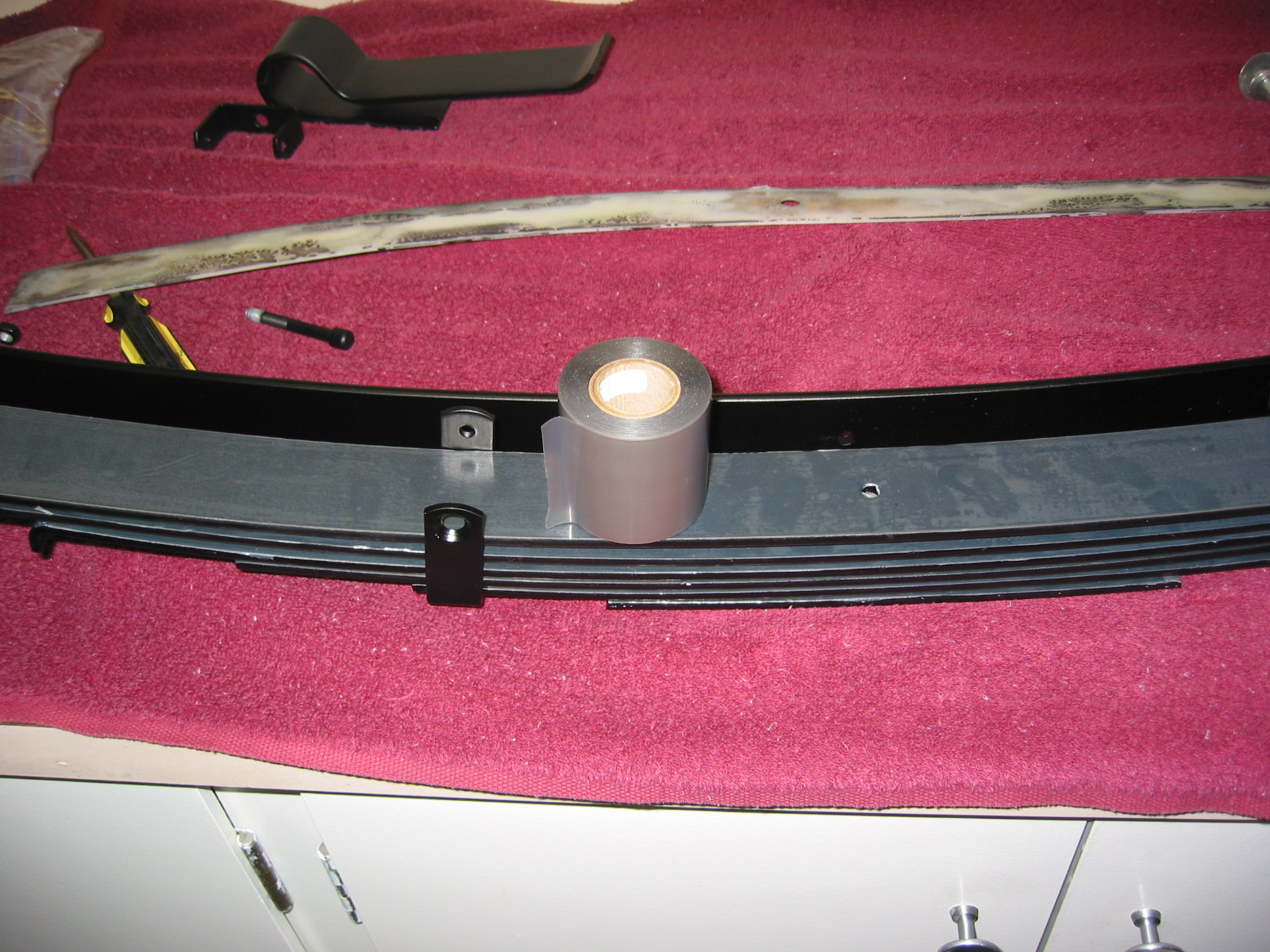
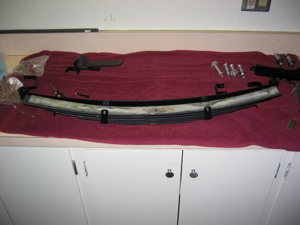
Rear Leaf Spring Assembly – The leaf springs were painted semi-gloss. I put a layer of teflon tape between each of the leaves to provide for smoother action between each of the leaves. It should help to eliminate creaks and moans later. The finished products looked very nice.
Rear spring glide strips 1

Rear springs teflon tape
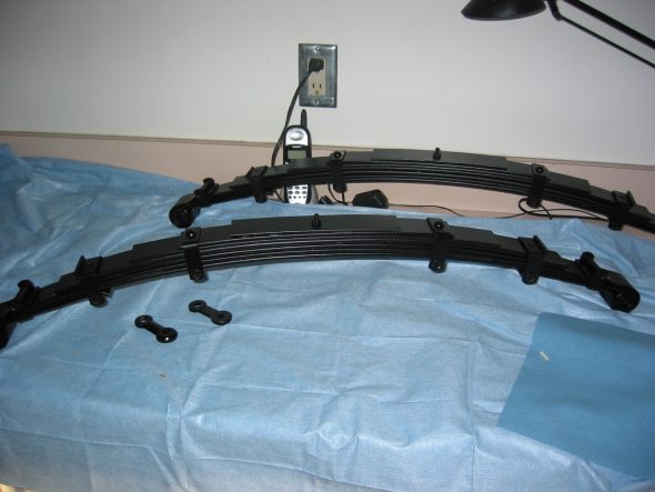
Rear springs completed
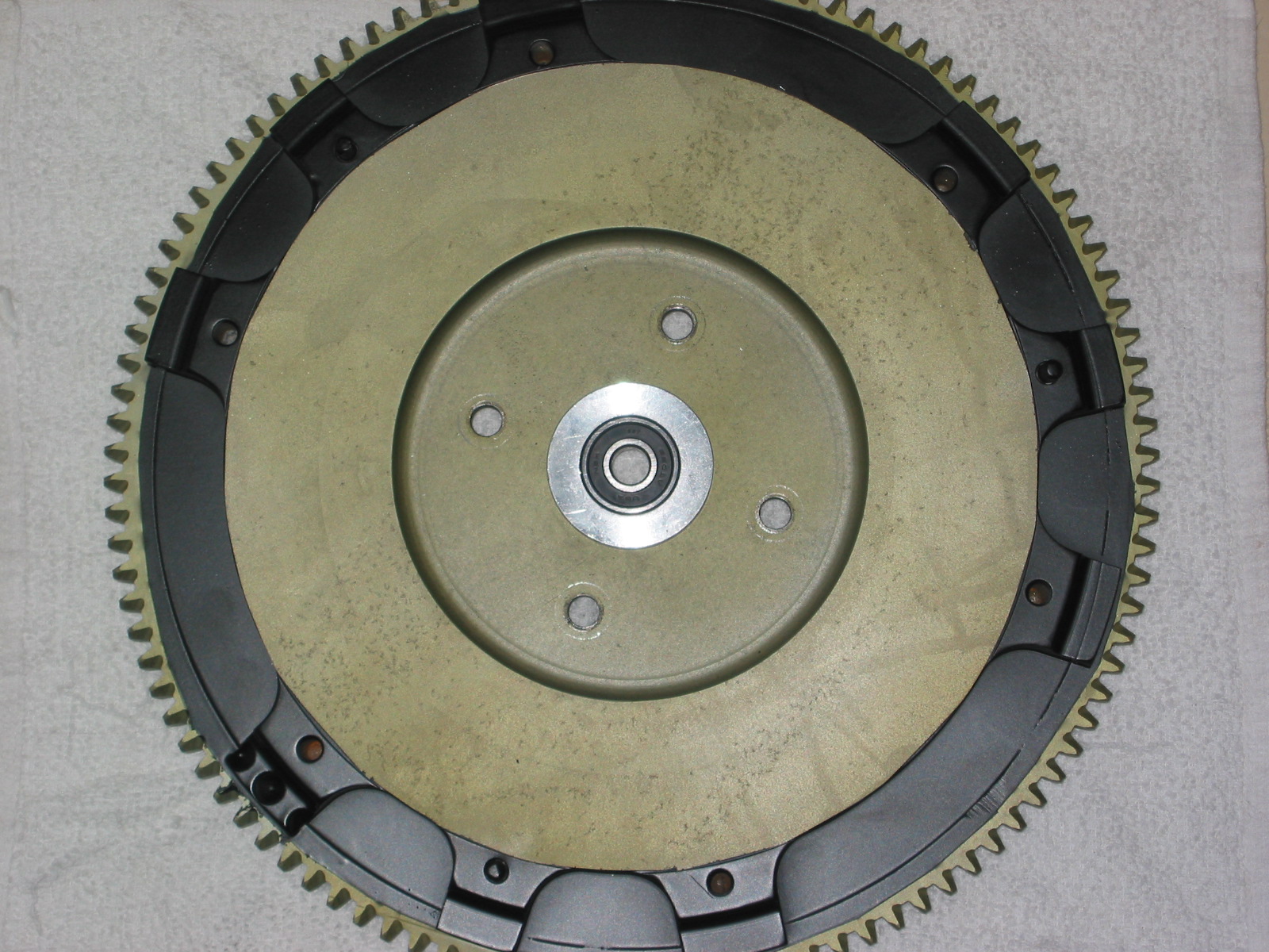
Smitty Toyota Transmission Conversion and Clutch Assembly – I wanted to see how the conversion assembly was going to fit so I decided to rmove the gearbox from the bell housing and set things up. The lightened flywheel from Bill Bolton had been cleaned up and painted just for some rust protection. I inserted the aluminum pilot bushing with bearing pressed in by using my lead knock-off hammer and soft drift to keep from damaging the aluminum.
Flywheel Smitty Pilot Bearing
Crank Rear Oil Seal – I will be purchasing an improved crank rear oil seal which will require some modification of the backplate, but for now I just wanted to see how things were going to fit, so I used the backplate as it was. I then fit the flywheel to the crank. Although not in the image below, I will be using the flywheel bolt lockdown tab washers.
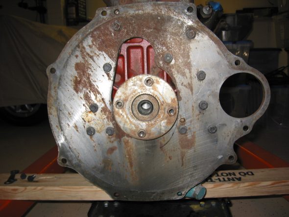
Engine Backplate
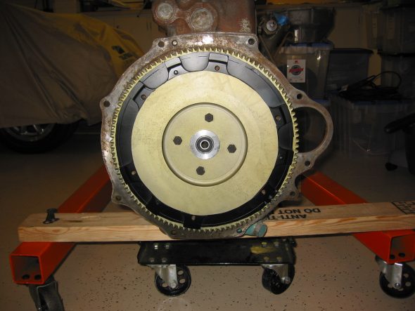
Flywheel installed 1
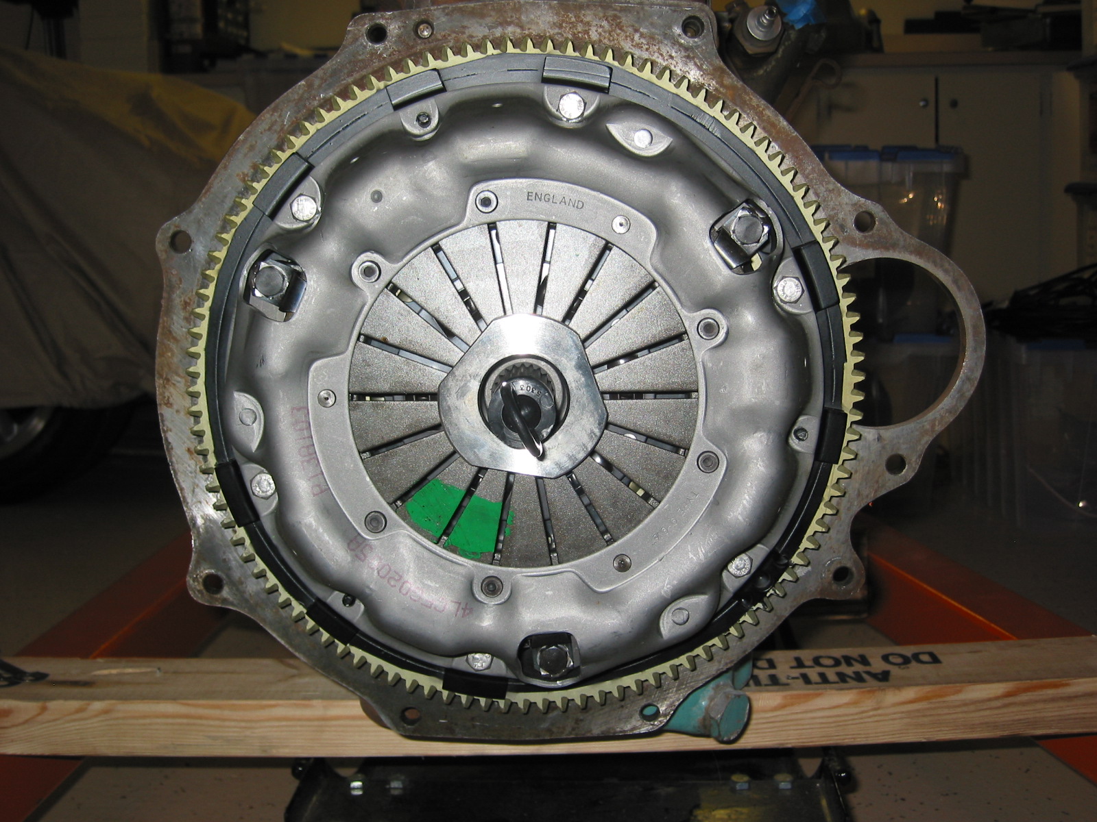
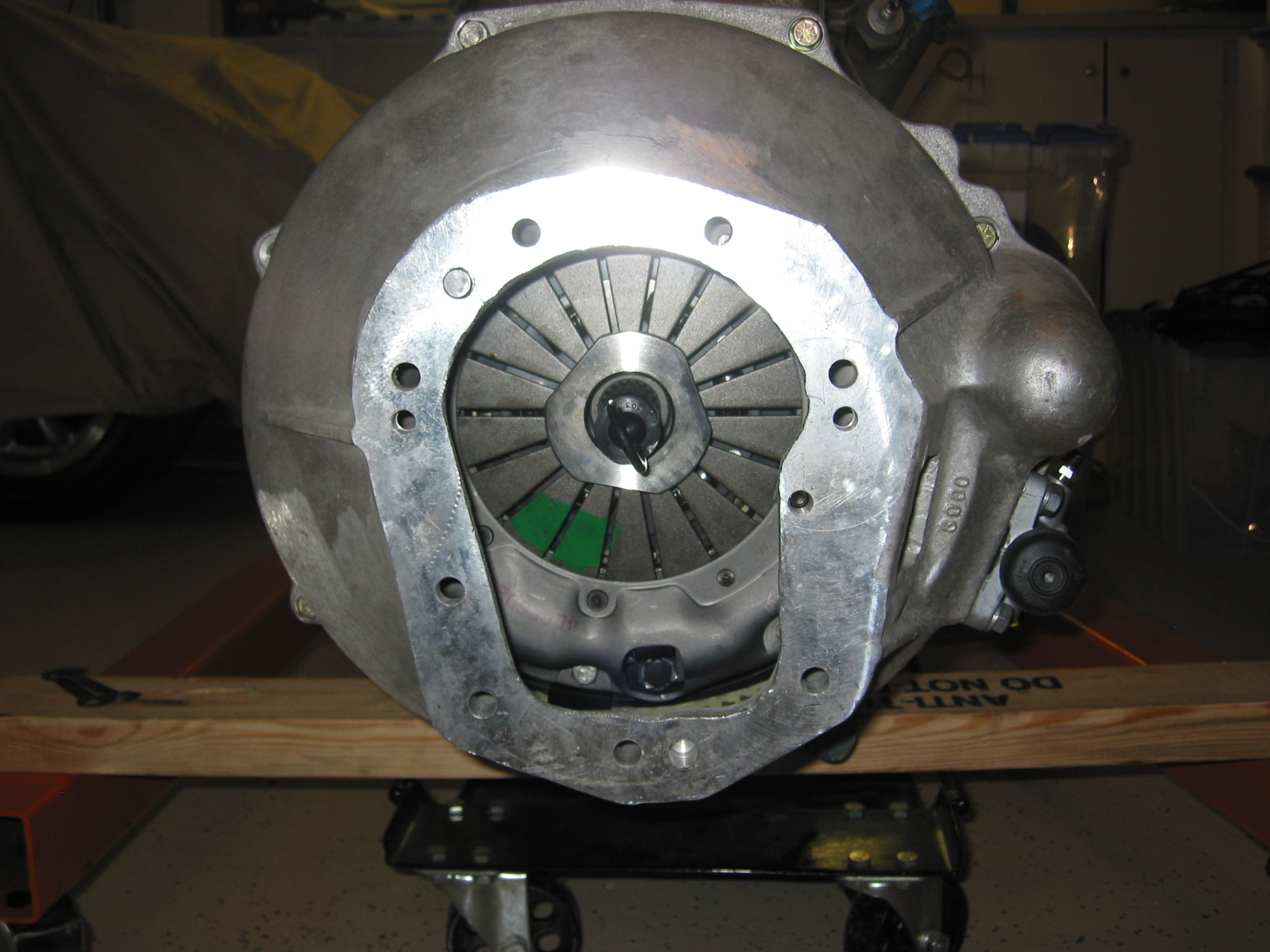
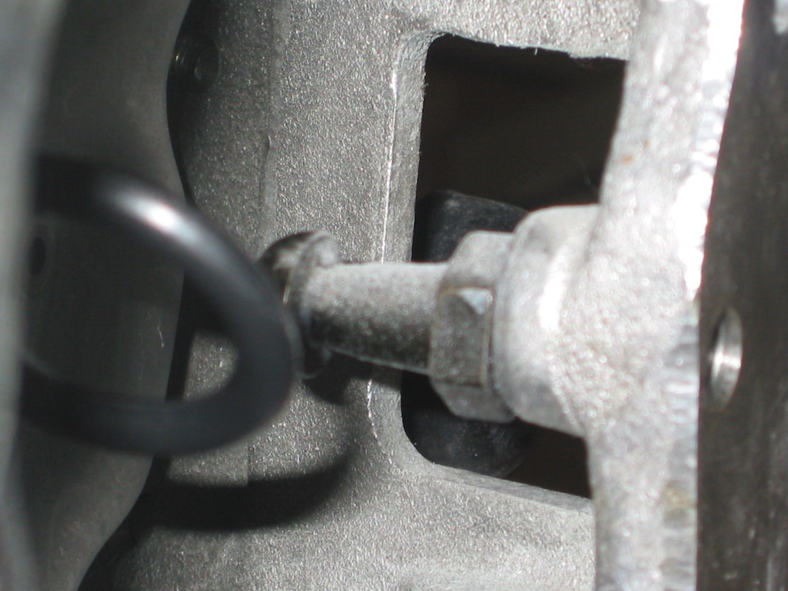
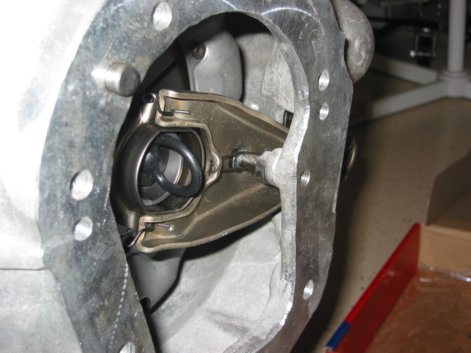
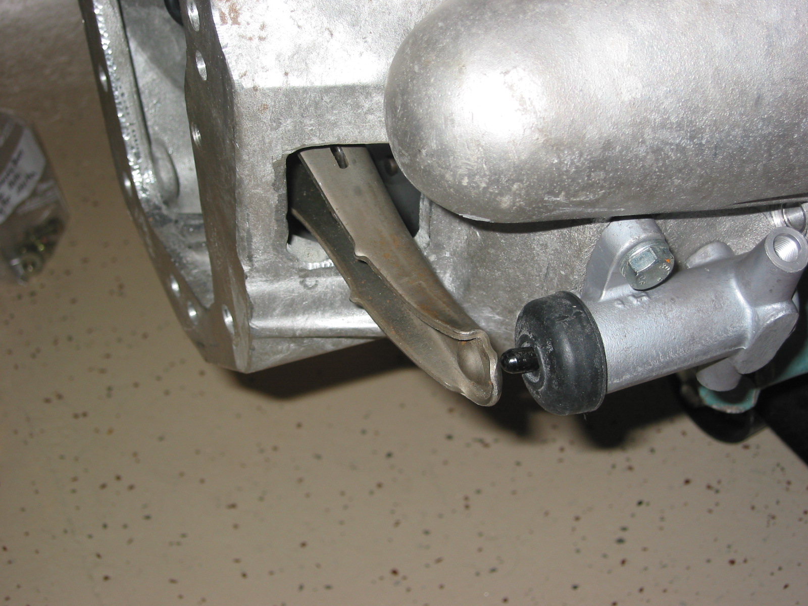
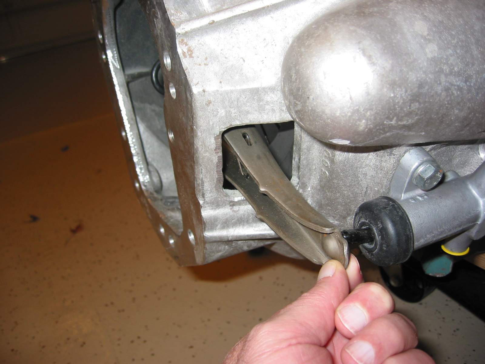
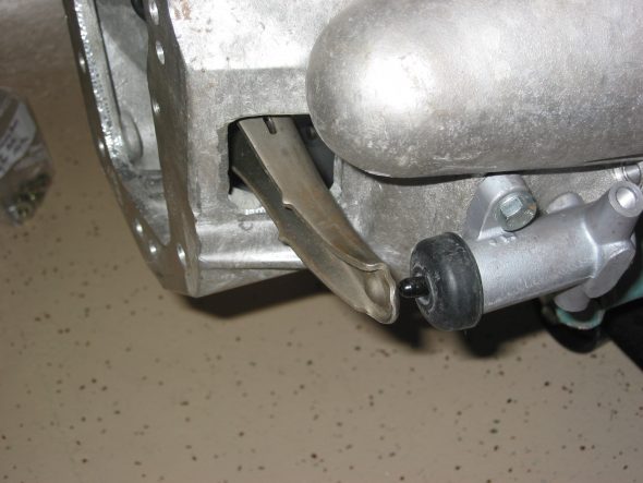
Then I installed the Pressure plate using the Smitty supplied clutch disk (thicker than stock Toyota) and centered it using the alignment tool supplied in kit. After installing the bell housing it became obvious that the throw out arm did not have sufficient travel without hitting the back edge of the opening in the housing. I will add some length (others have suggested about 3/16” to the pivot fulcrum to gain the travel required.

Clutch plate assembly
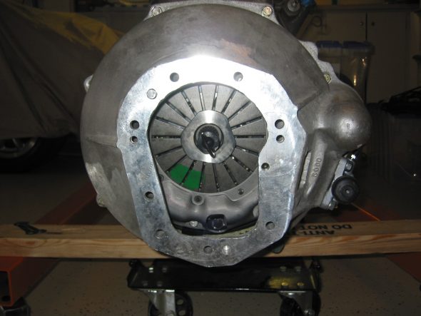
Bell housing installed
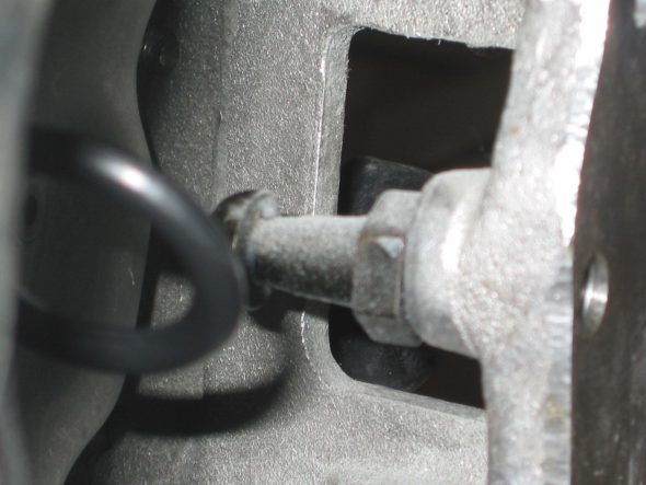
Clutch arm pivot 2
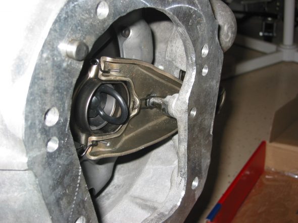
Throw out bearing clutch arm 1
Throw out bearing clutch arm 2
throw out arm 1
November 27, 2006
Back to the Engine Work
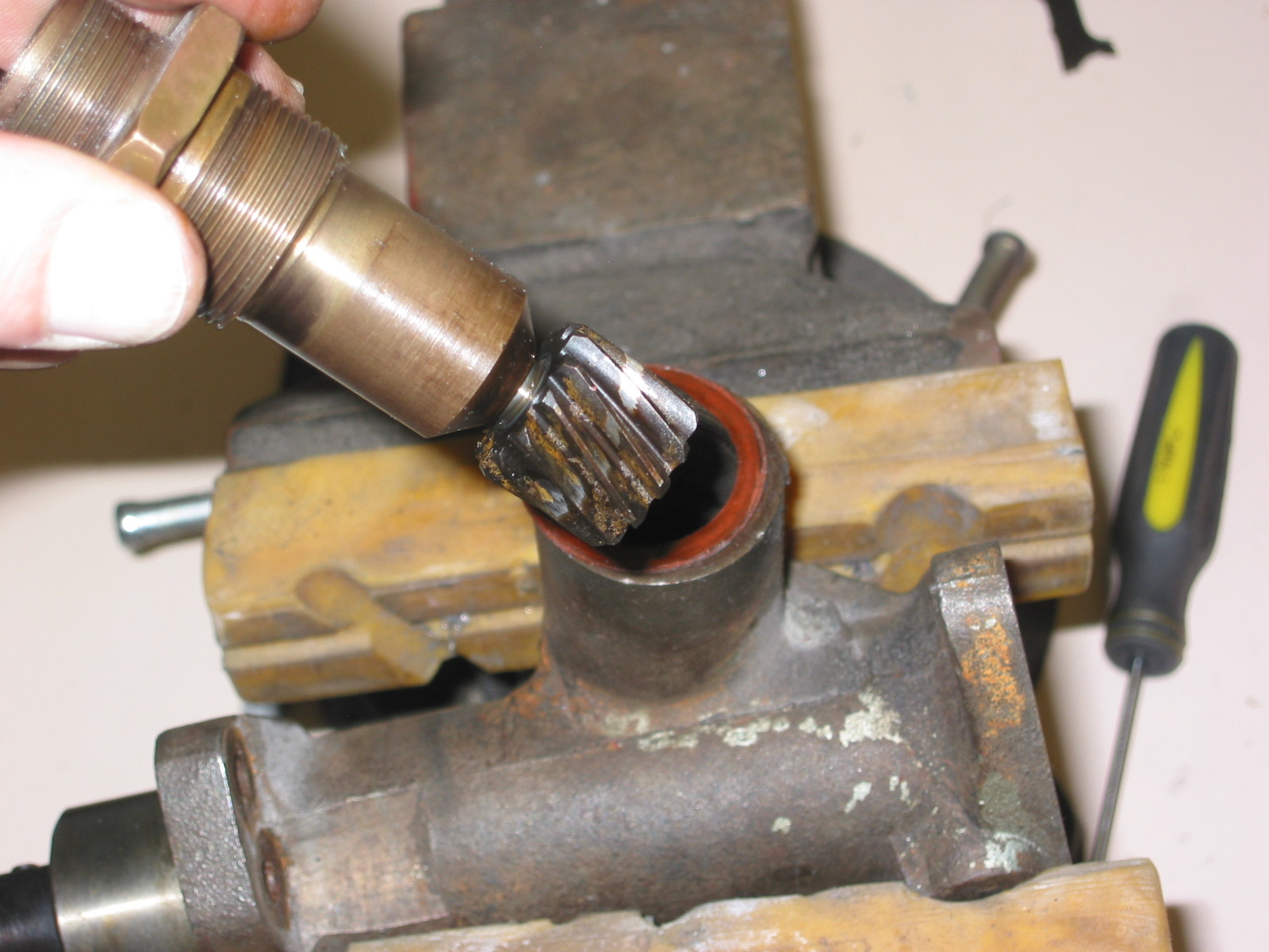
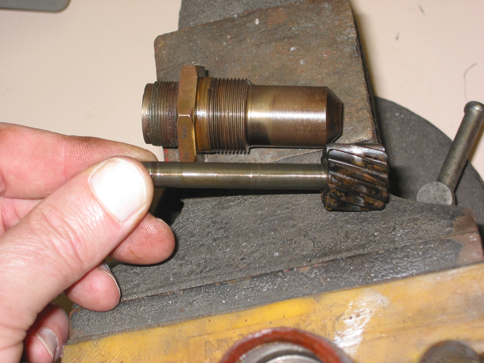
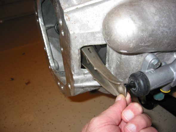
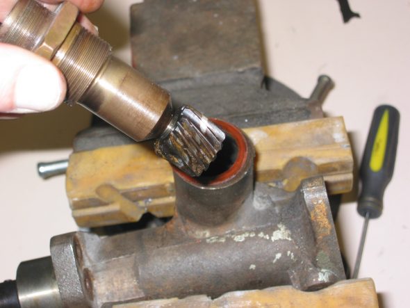
Tach Drive Housing – Detached the tach drive housing from the block. Three ¼” x 7/8” Hex head bolts with flat and lock washers. As per the manual, pulled out the gear drive with a 3” x 5/16” bolt attached to the threaded hole in the drive. Will need to install new rubber seals in the unit.
Tach Drive assembly 1

Tach Drive assembly 2
Tappet Cover Plates – There are three covers. The rear cover with the breather pipe is secured with one 1 ¼” x 5/16” hex head bolt with a copper washer and a cork gasket. The center cover is also attached with one 1 ¼” x 5/16” hex head bolt with copper washer and cork gasket. The front cover which is much heavier to support the weight of the generator is secured with five ¾” x 5/16” hex head bolts with copper washers.
Rear Side Cover

Center Side Cover
Front Side cover 1
Heater Water Valve – Secured by two 5/8” x ¼” hex head bolts and washers.

Heater water valve
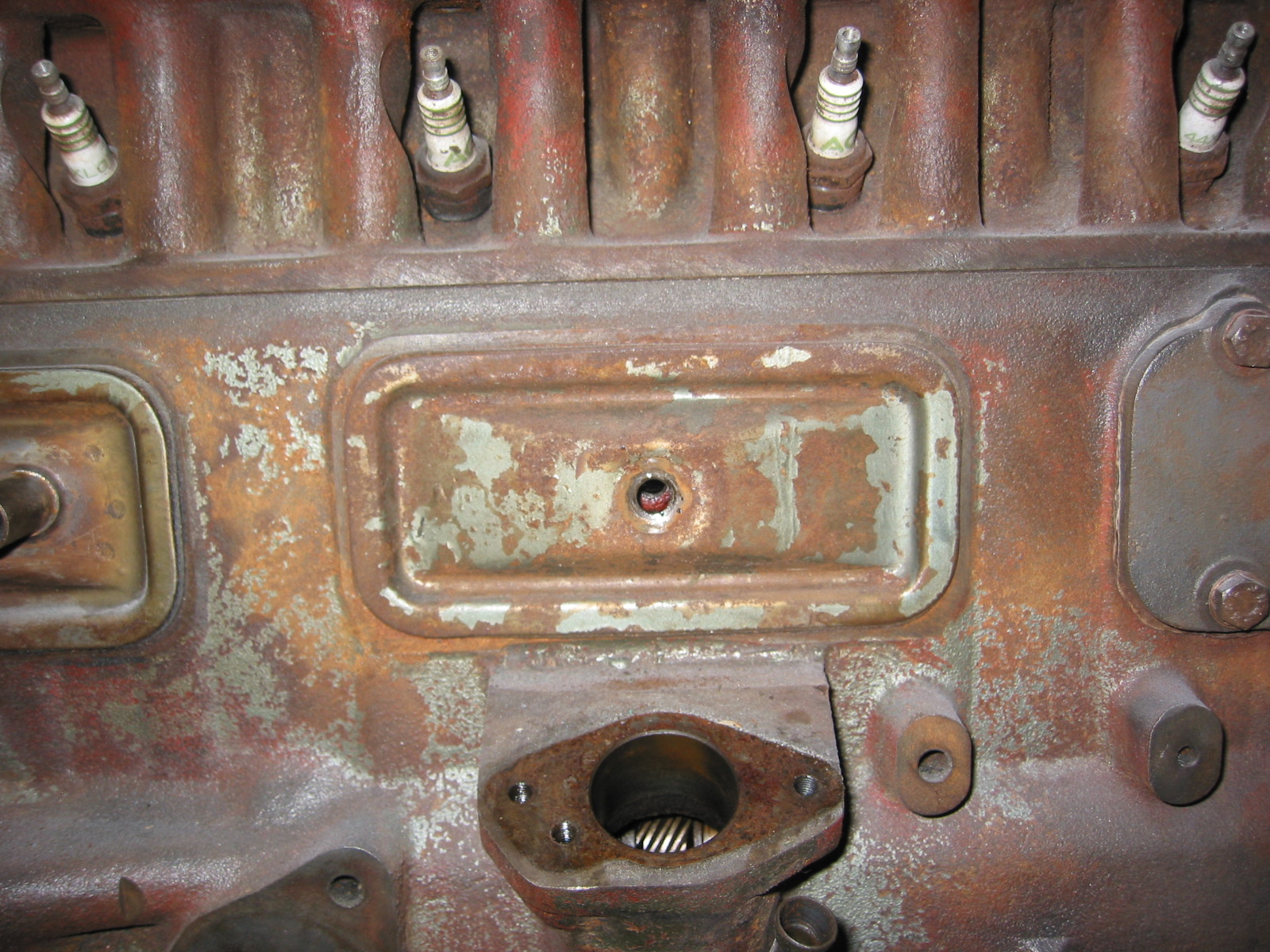
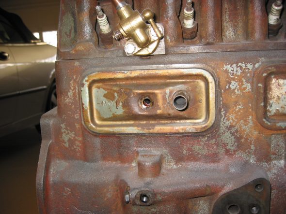
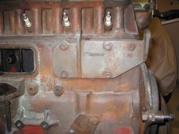
Blanking Plate – Located on the right side of the motor. Two hex head bolts 5/8” x 5/16.” Course threads with copper washers.
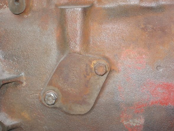
Blanking Plate
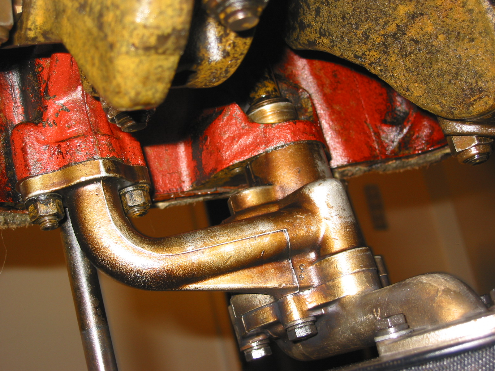
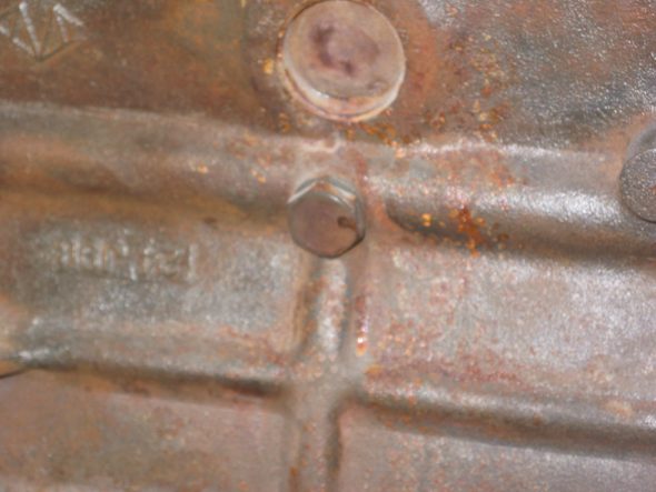
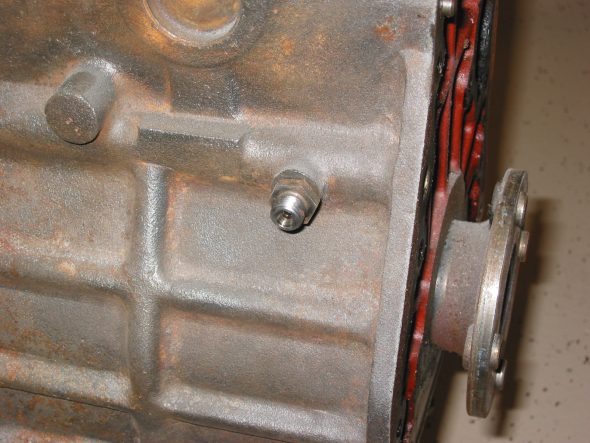
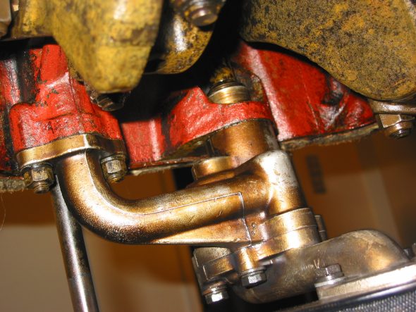
Oil Pipe Fitting, back side – One hex head bolt, 3/8” x 5/16” with copper washer.
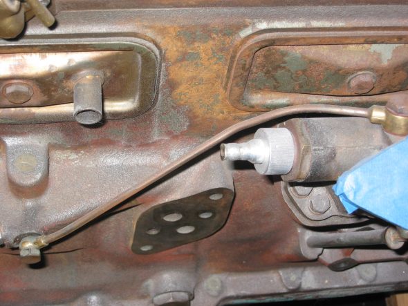
Oil Feed Pipe

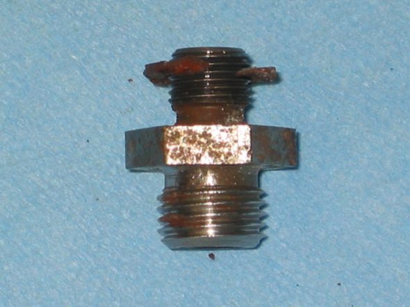
Oil Feed Bolt
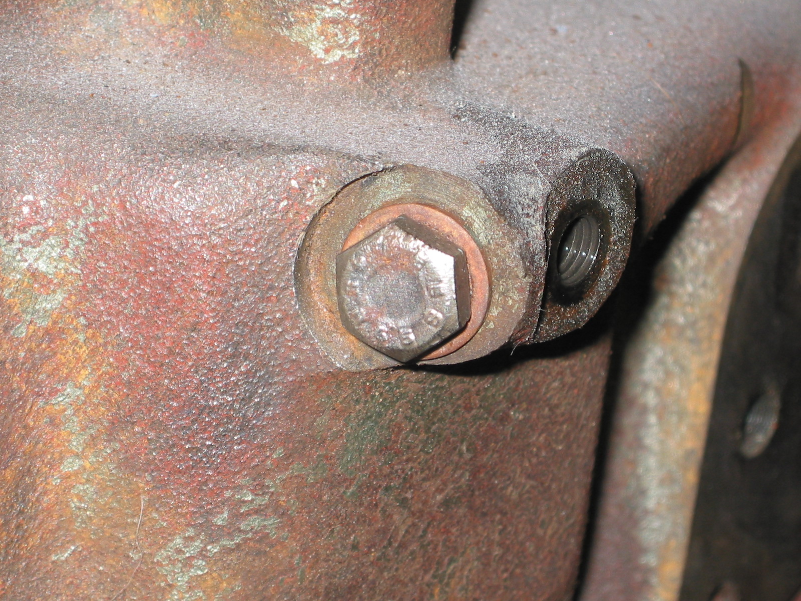
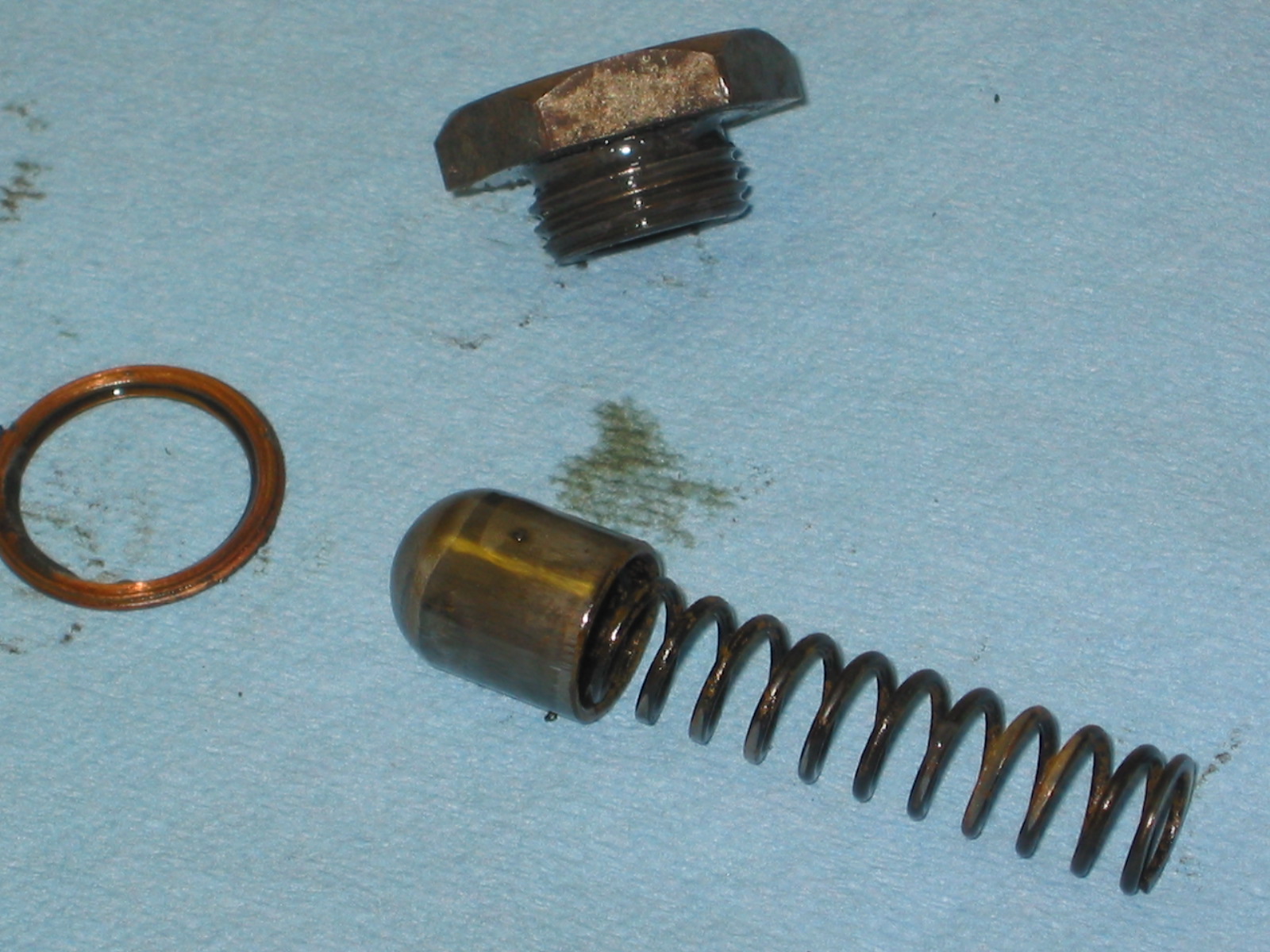
Oil Pressure Relief Valve – One 1 1/8” (wrench size) hex head bolt x 3/8” long. Copper washer with spring and cup.
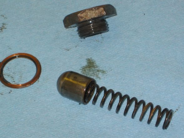
OIl Pressure Relief Valve 2
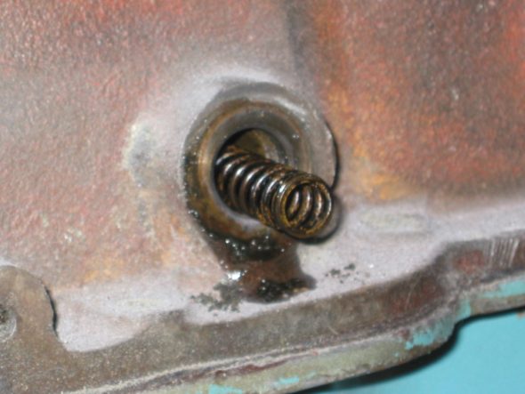
OIl Pressure Relief Valve 1
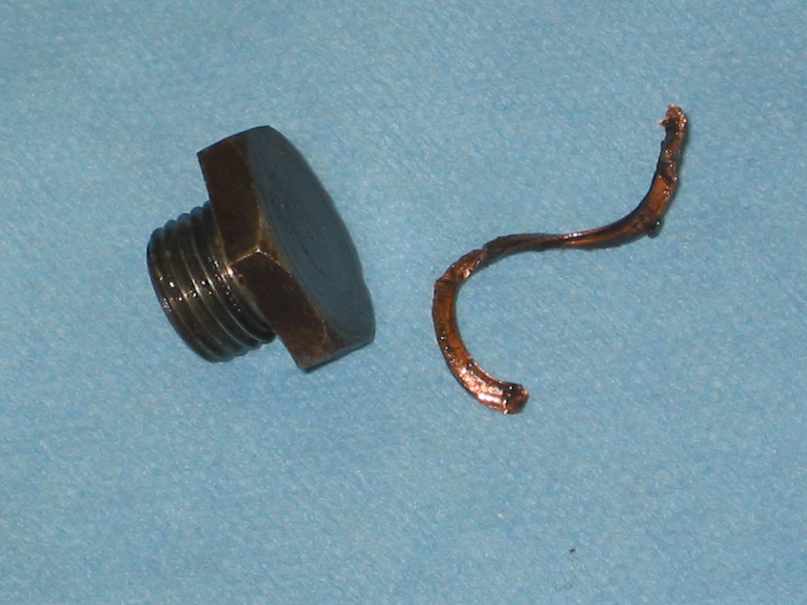
Plug for Oil Filter Feeder Hole – Right side of block. One 7/8” (wrench size) hex head bolt 3/8” long, with copper washer.
OIl Filter feeder hole plug 1

OIl Filter feeder hole plug 2
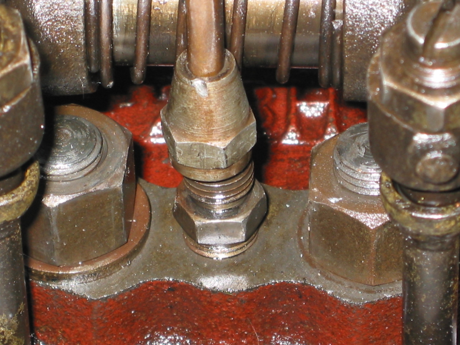
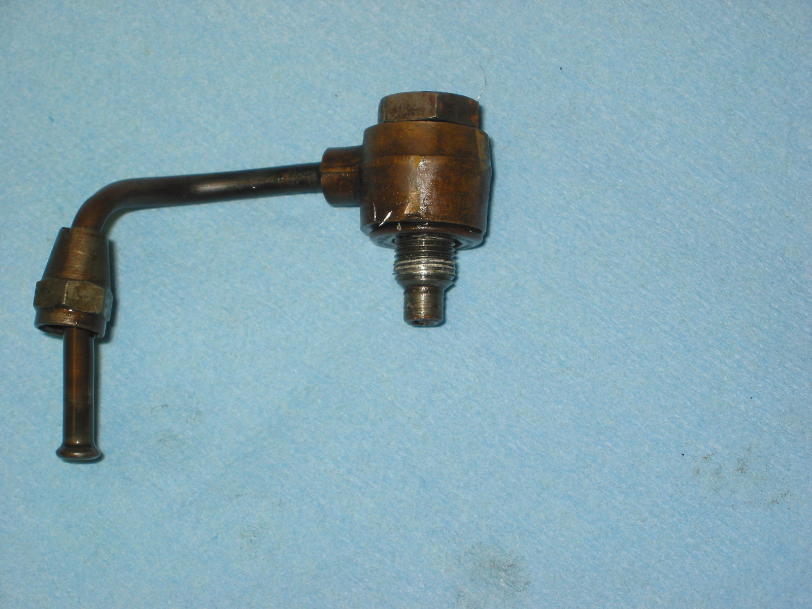
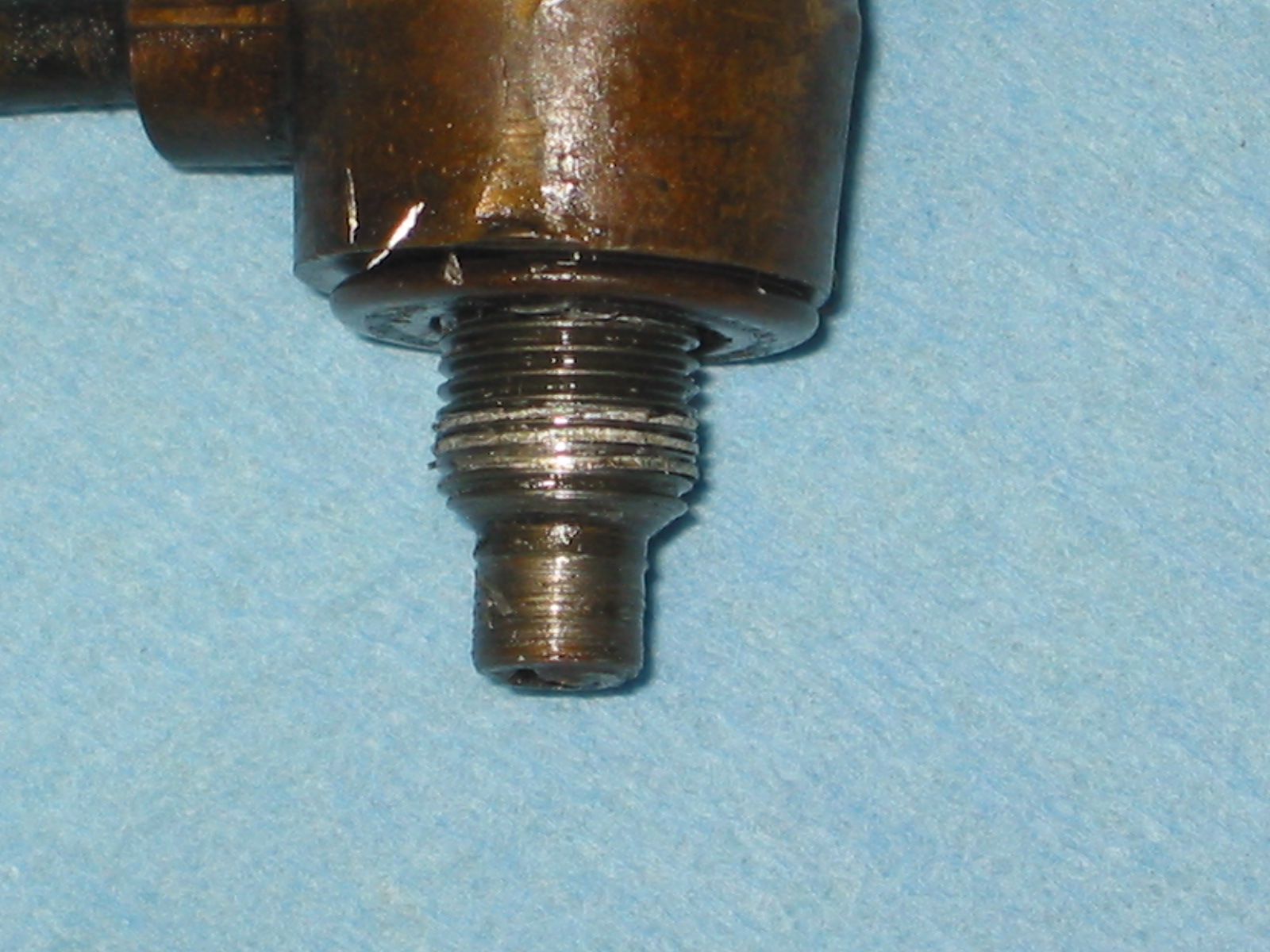
Union for Oil Gauge Pipe – Right side of block. Nut with pin hole. Fiber washer.
Oil Pressure Pipe Union 1
Oil Pressure Pipe Union 2
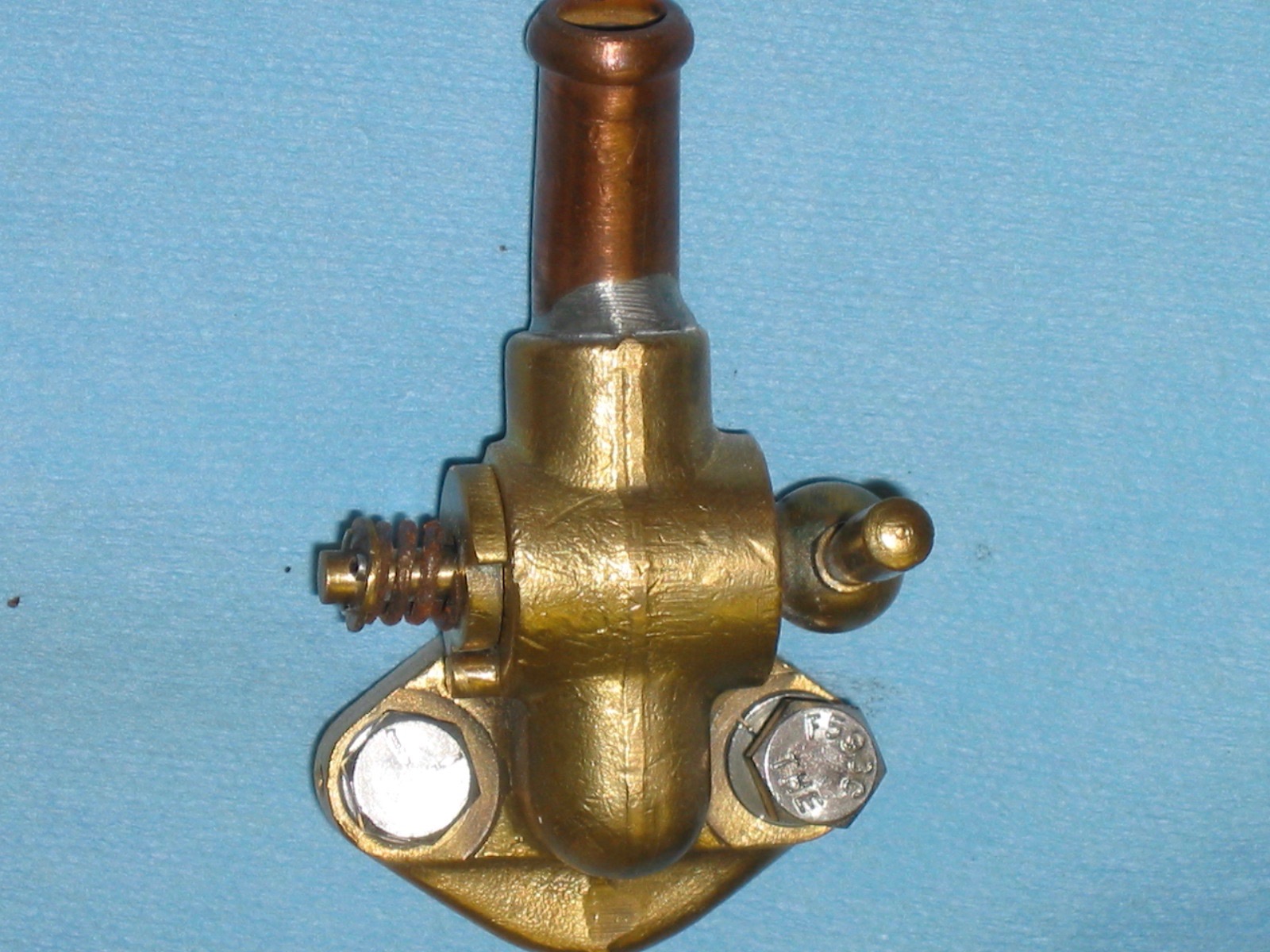
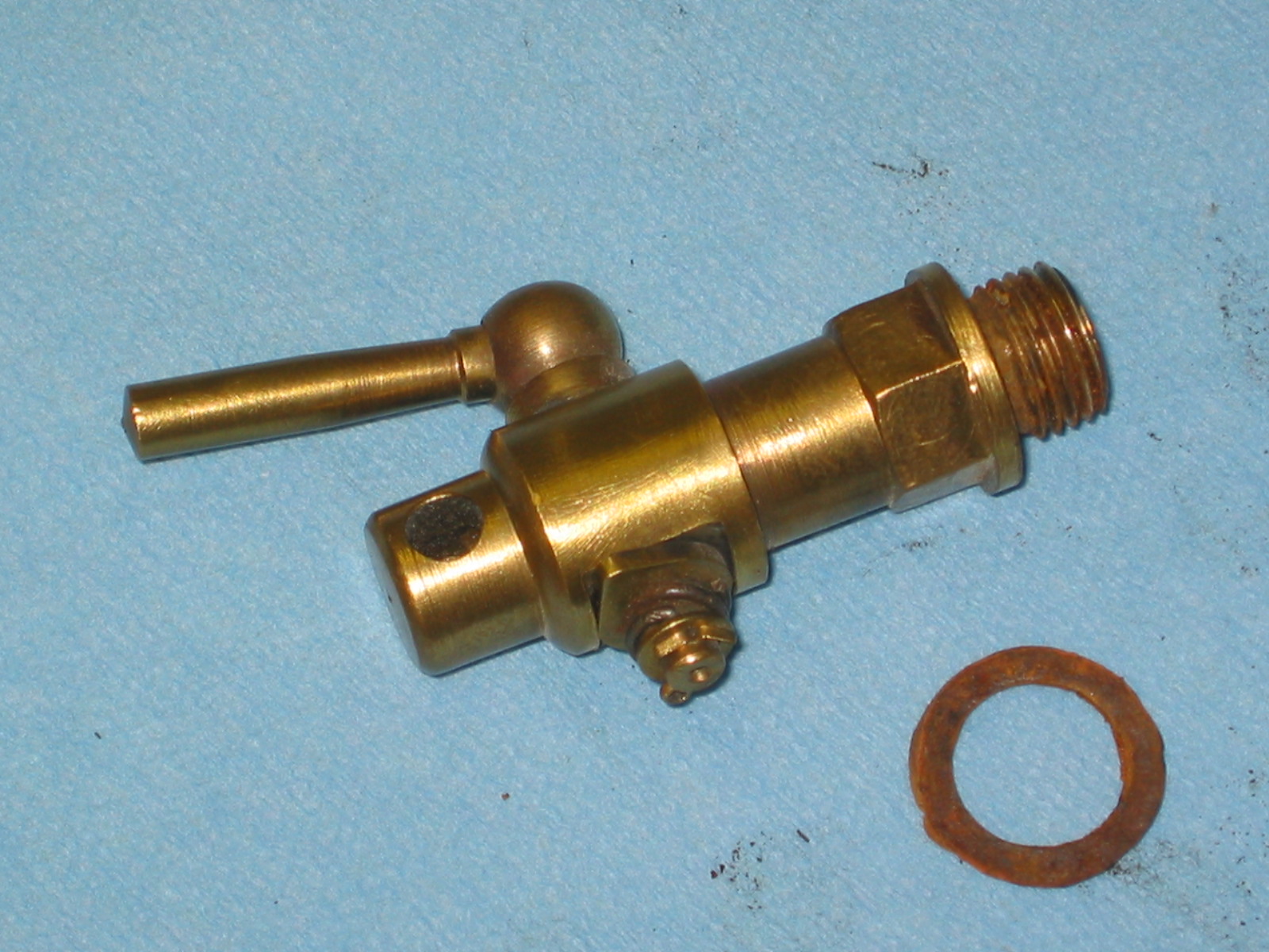
Block Drain Tap – Brass with fibre washer.
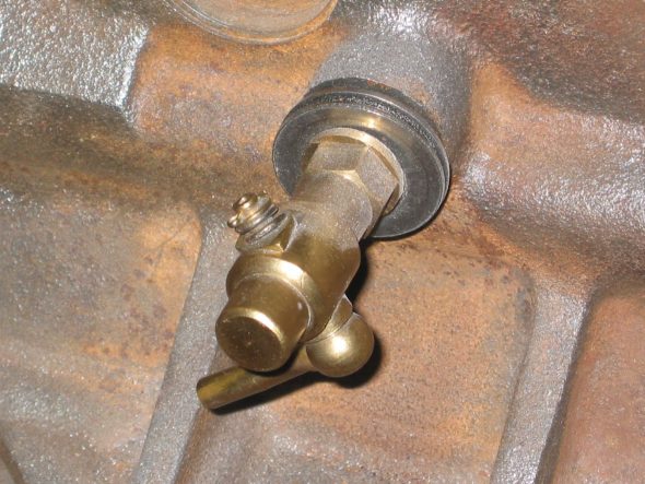
Drain Tap 1
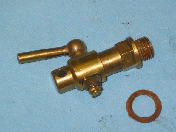
Drain Tap 2
Carb Drain Pipe Brackets – Located at the second and seventh oil sump mounting bolts from the font of the block. ¼” nuts used to secure the clips.

Fuel Drain Pipe Clip 1
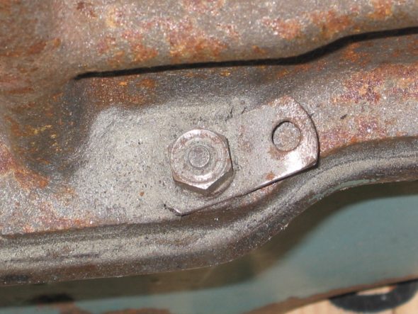
Fuel Drain Pipe Clip 2
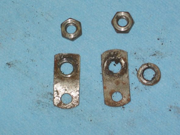
Fuel Drain Pipe Clip 3
November 27, 2006
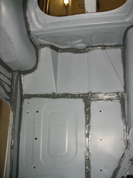
Jeremy’s Painting and Bodywork
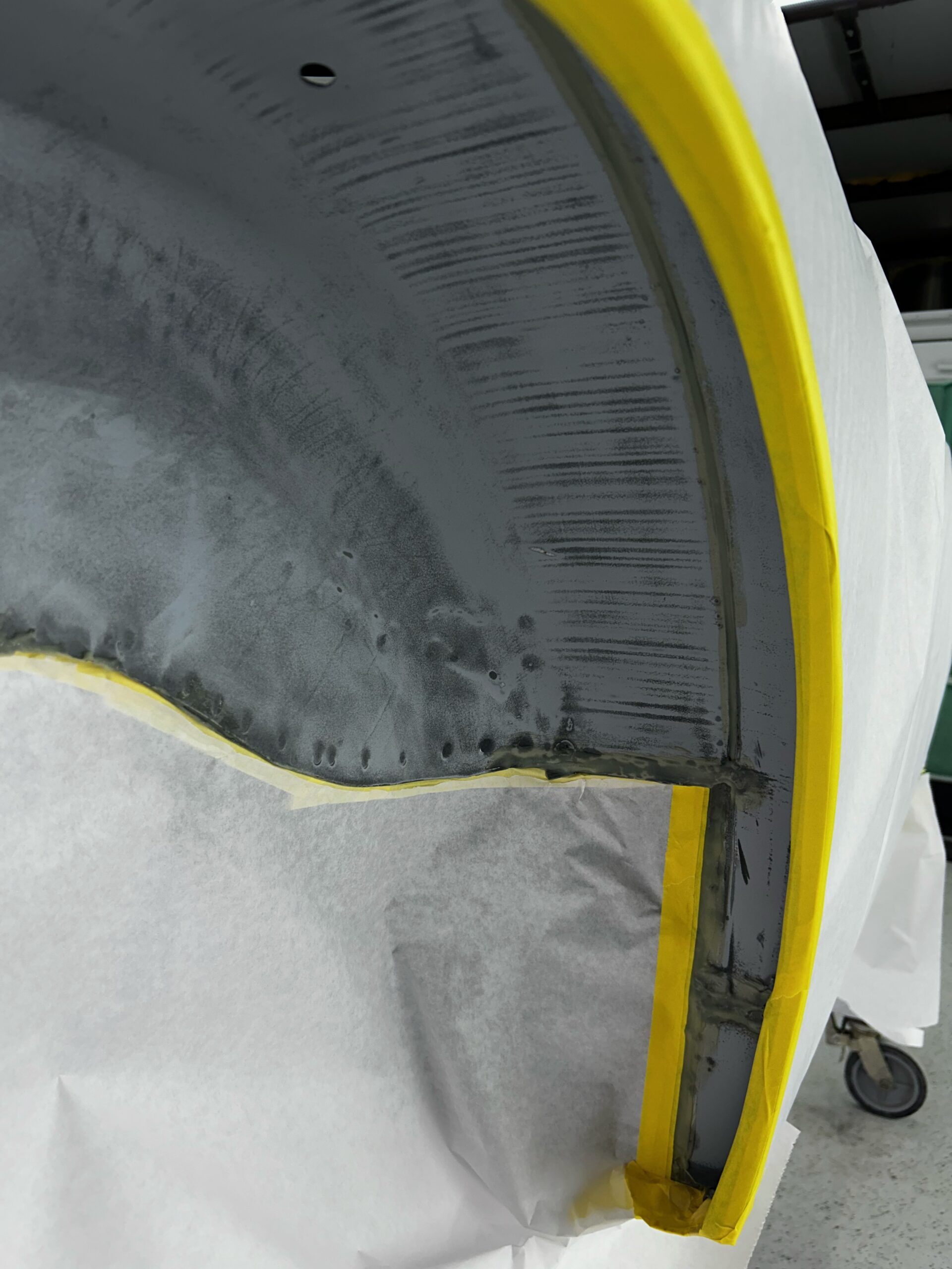
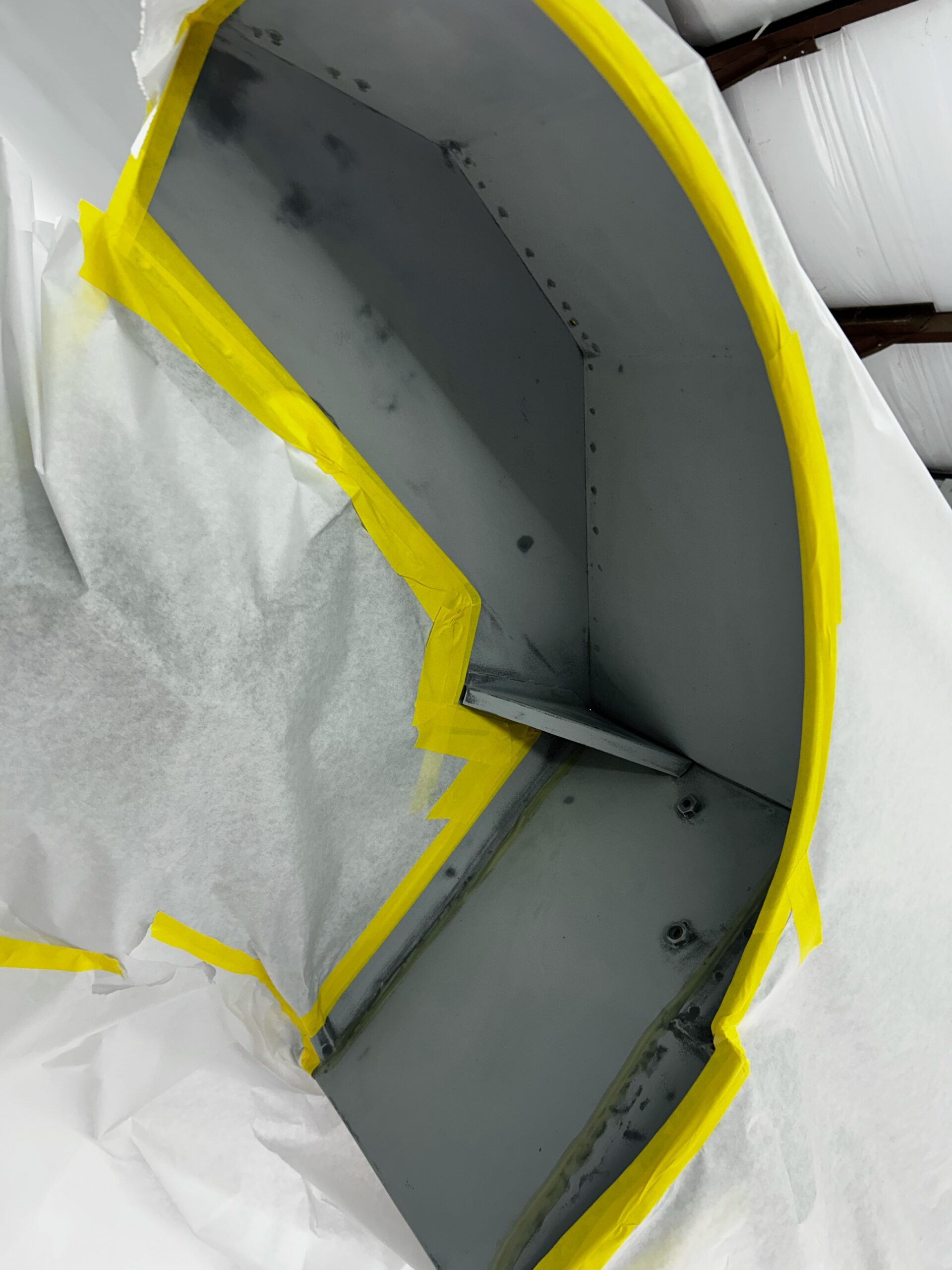
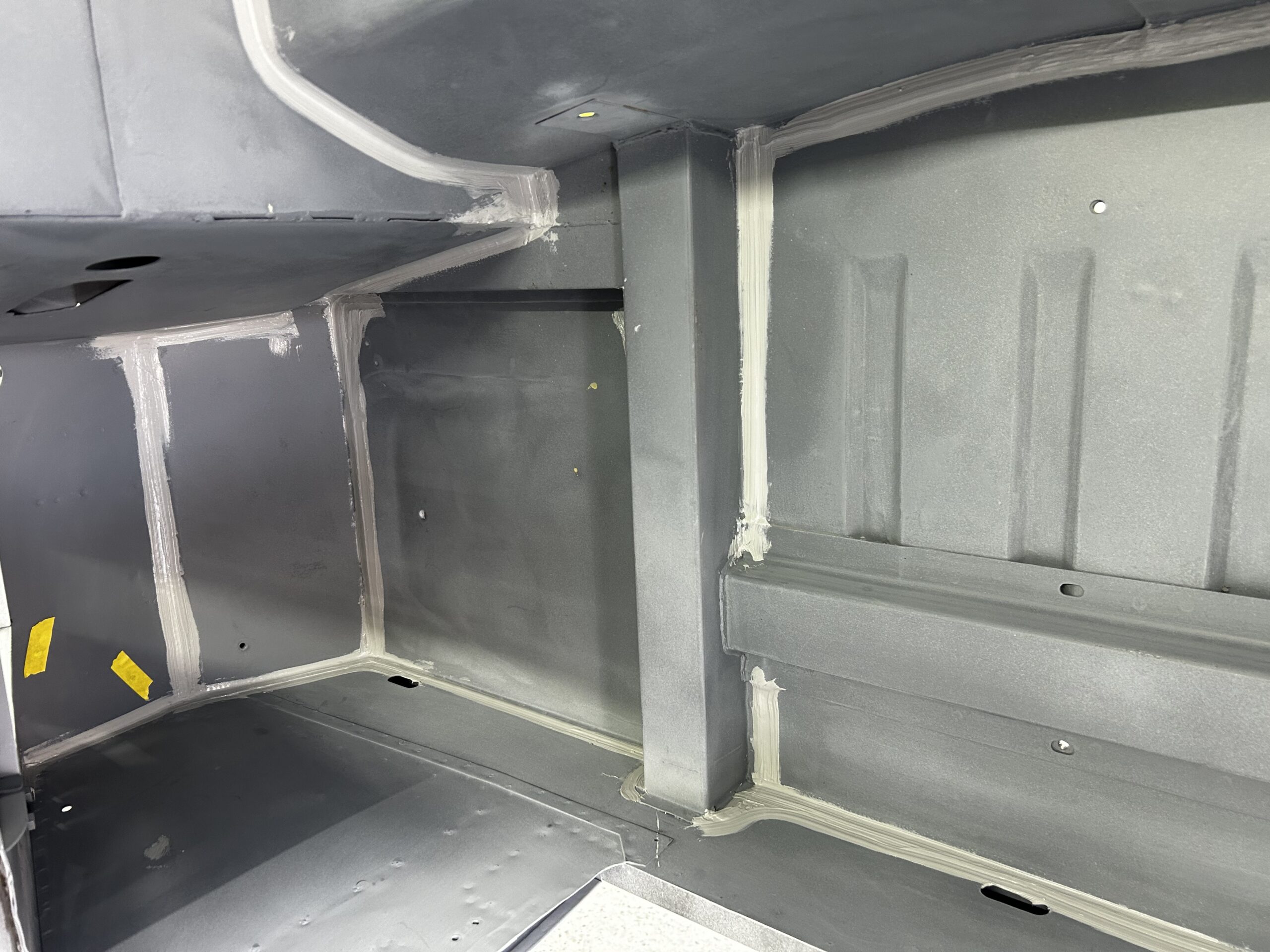
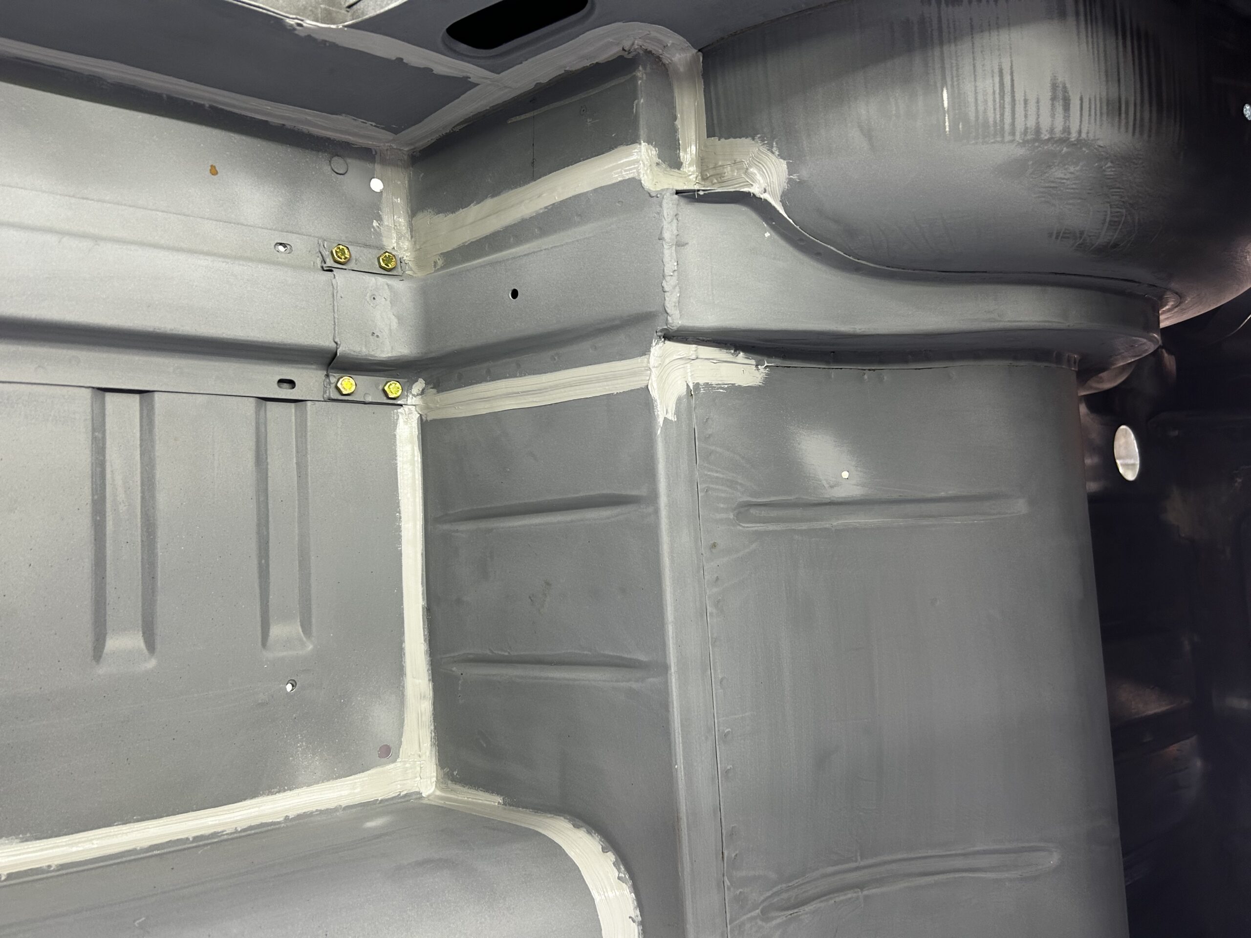
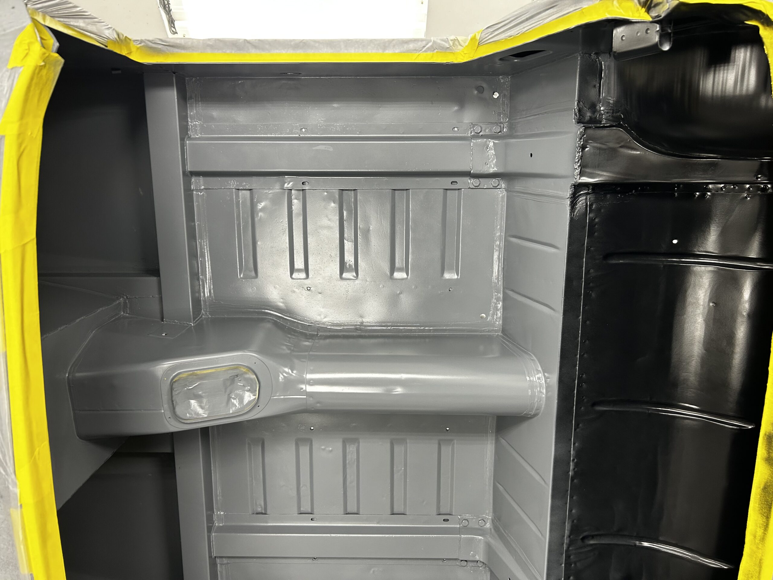
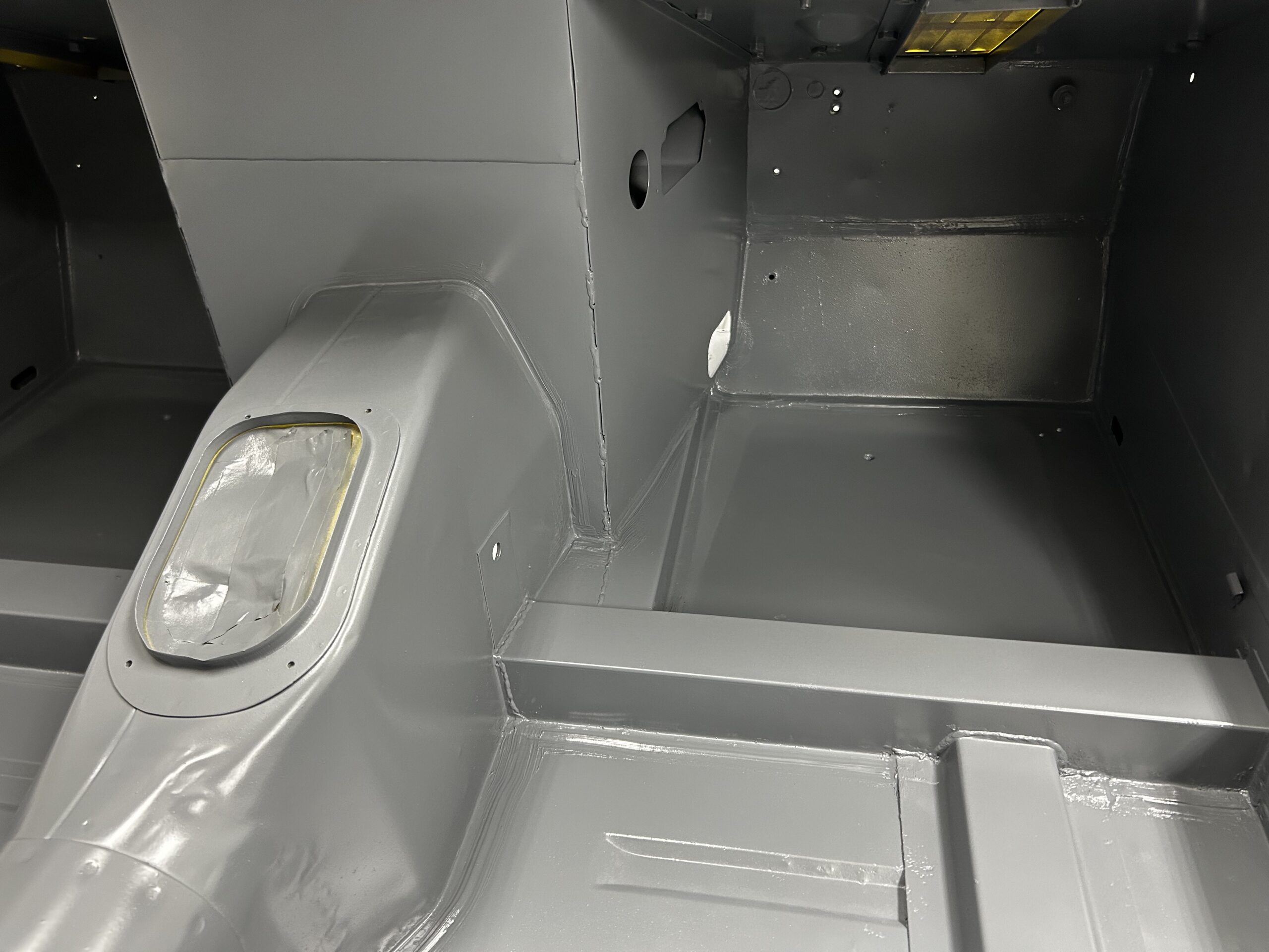
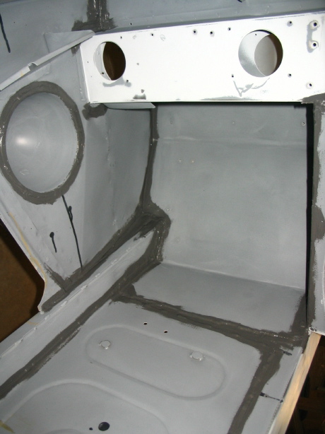
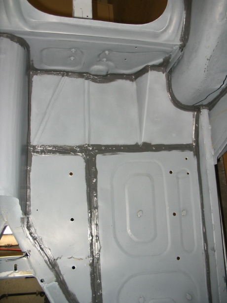
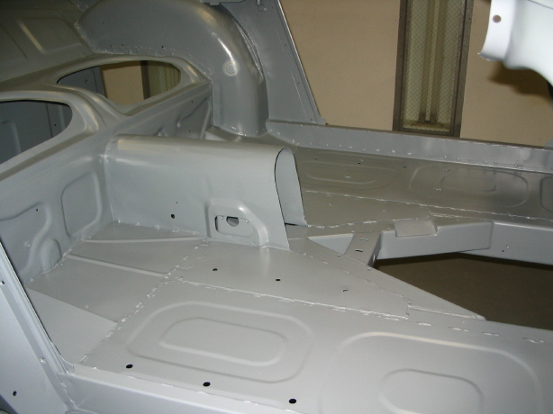
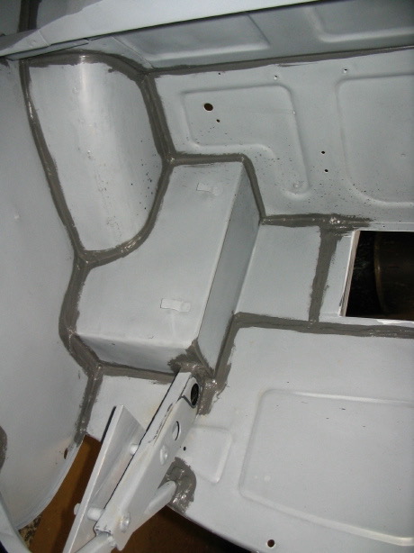
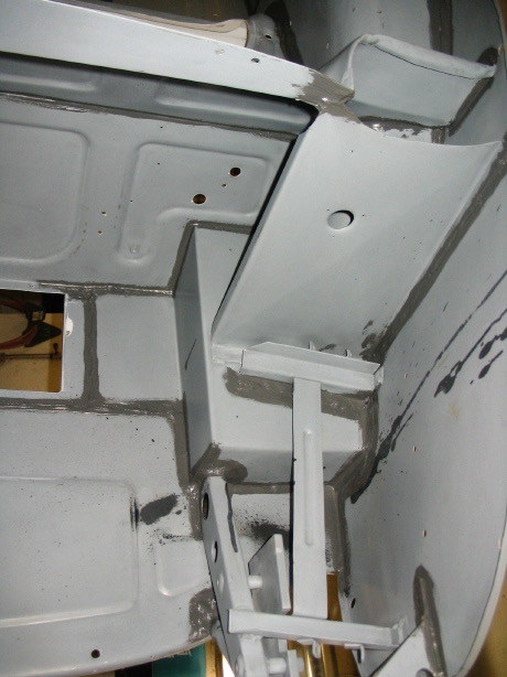
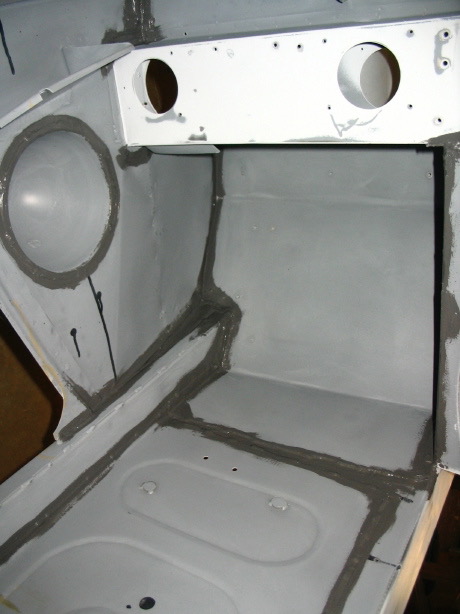
New Seam Sealer and Prep for Chip Protector – Jeremy finished the sanding work and installed seam sealer.

Seam sealer finished 1
Seam sealer finished 2

Seam sealer 4
Seam sealer 1
Seam sealer 2

Seam sealer 5
Seam sealer 8
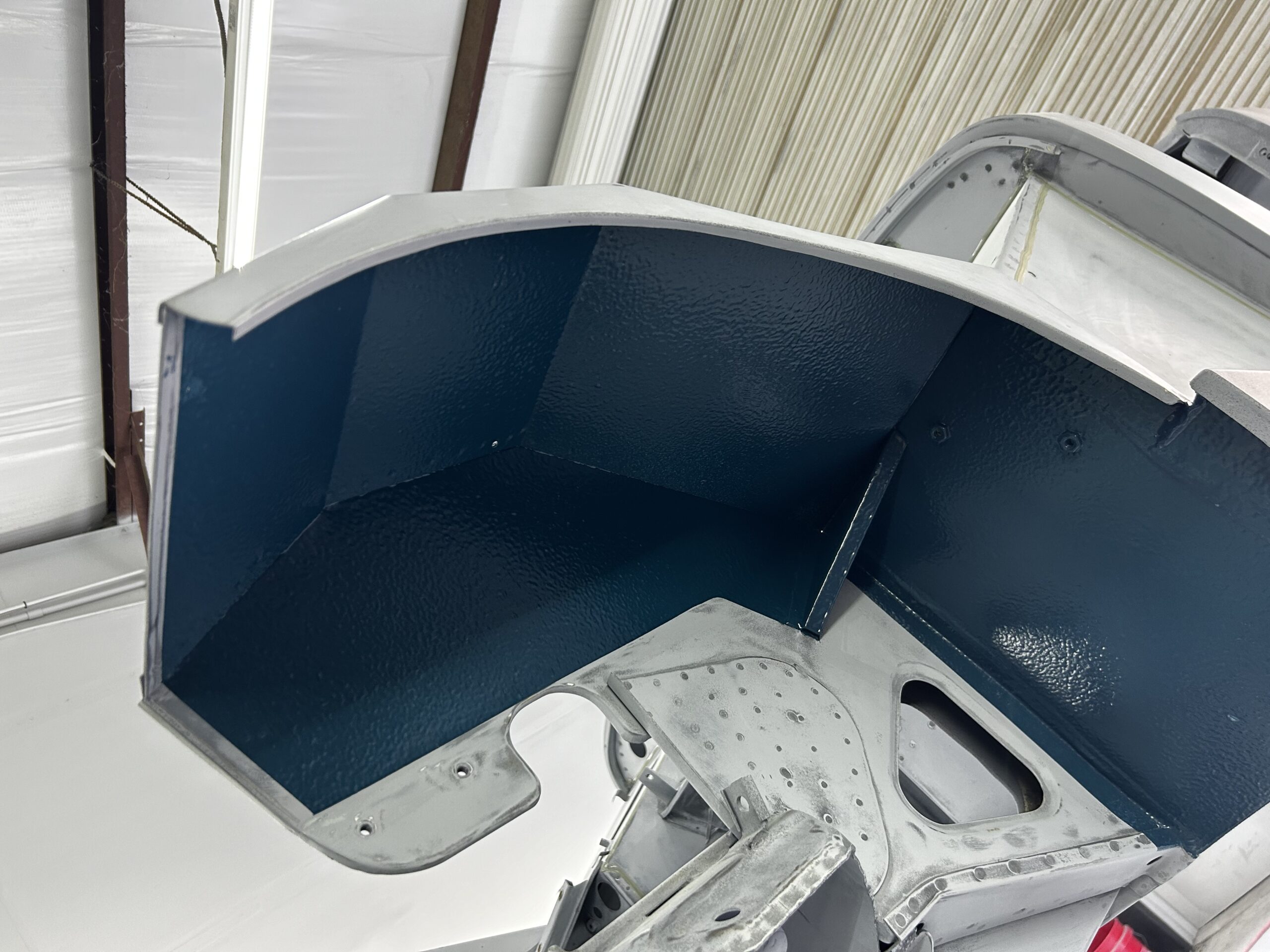
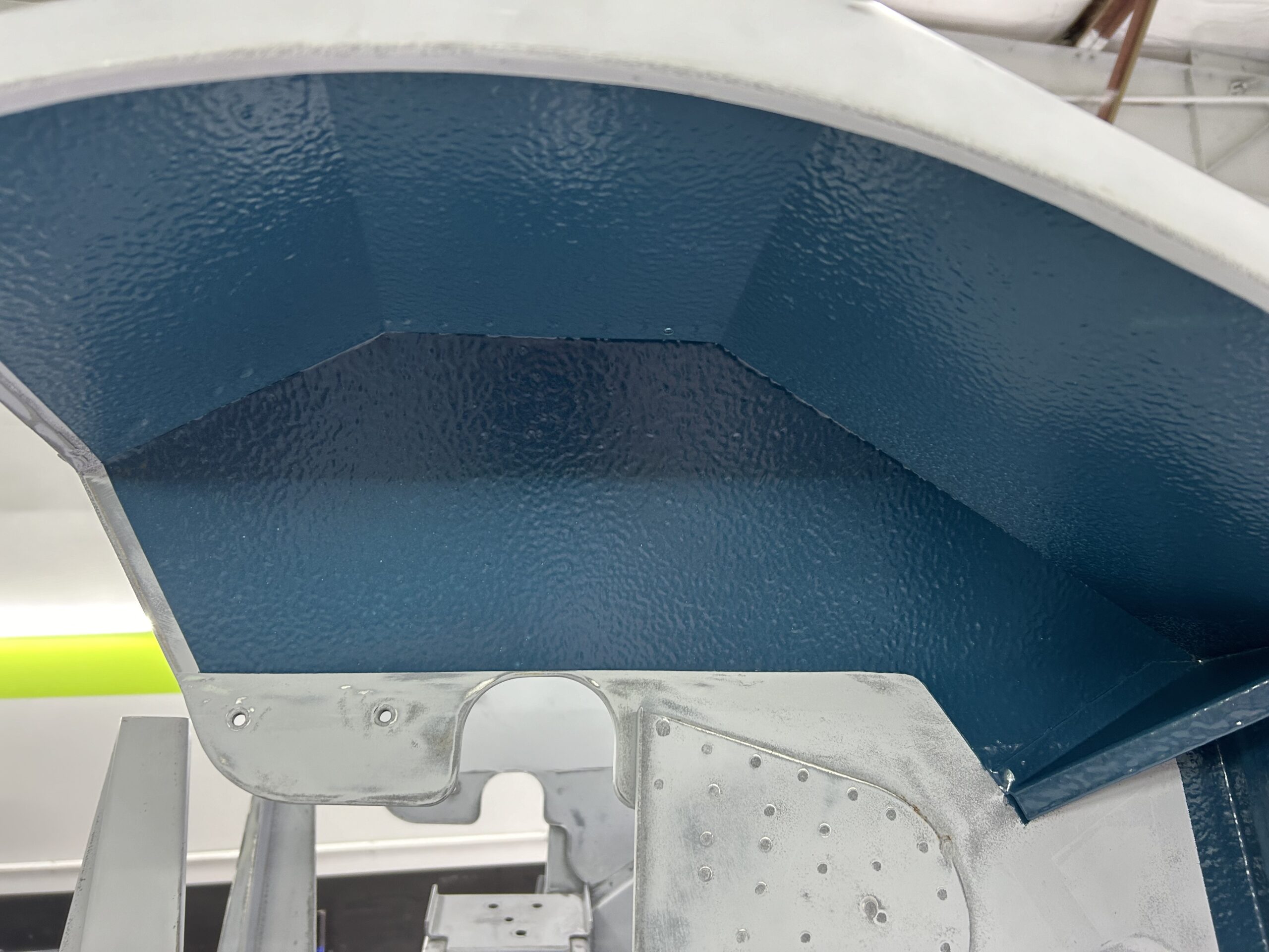
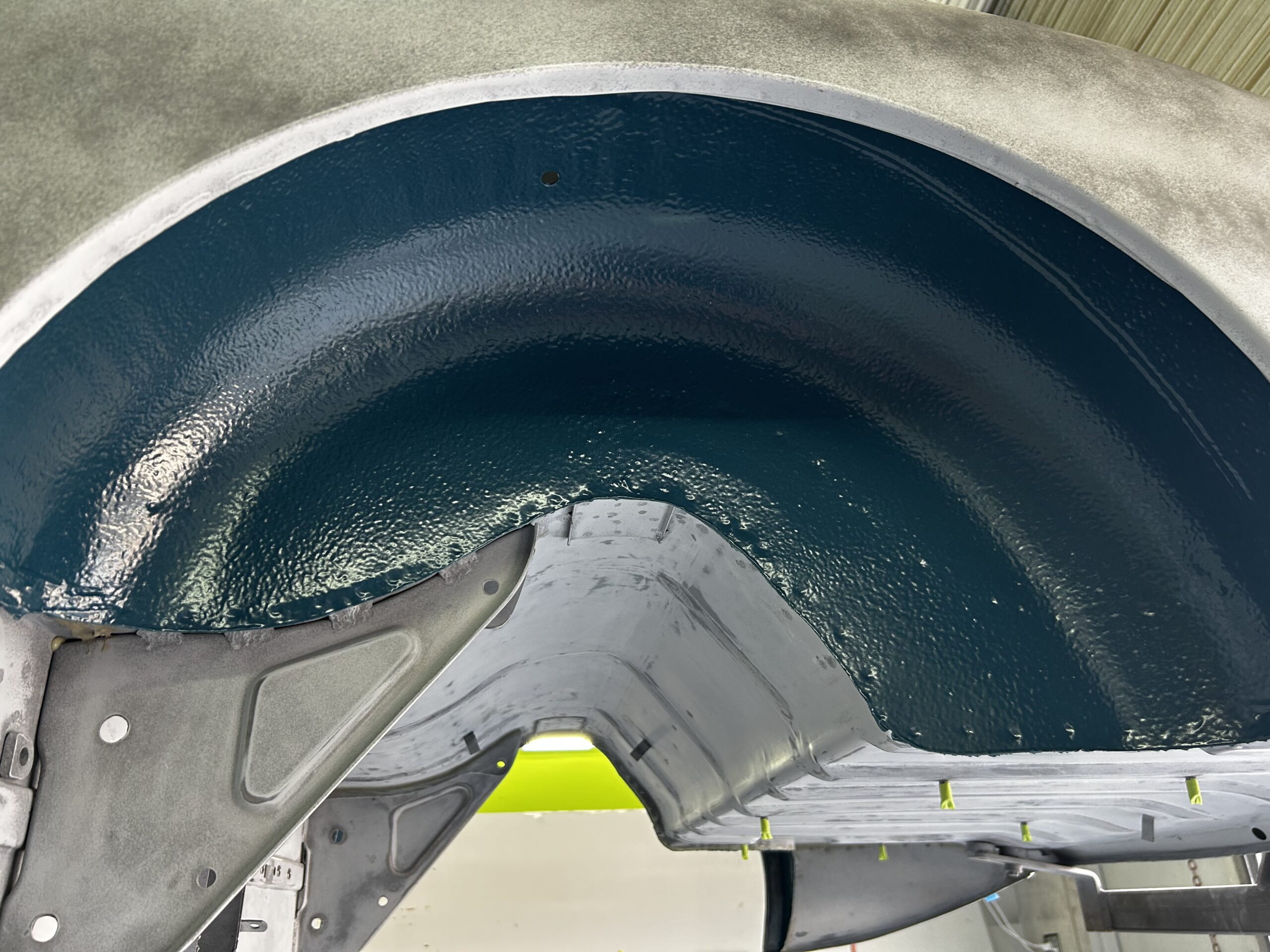
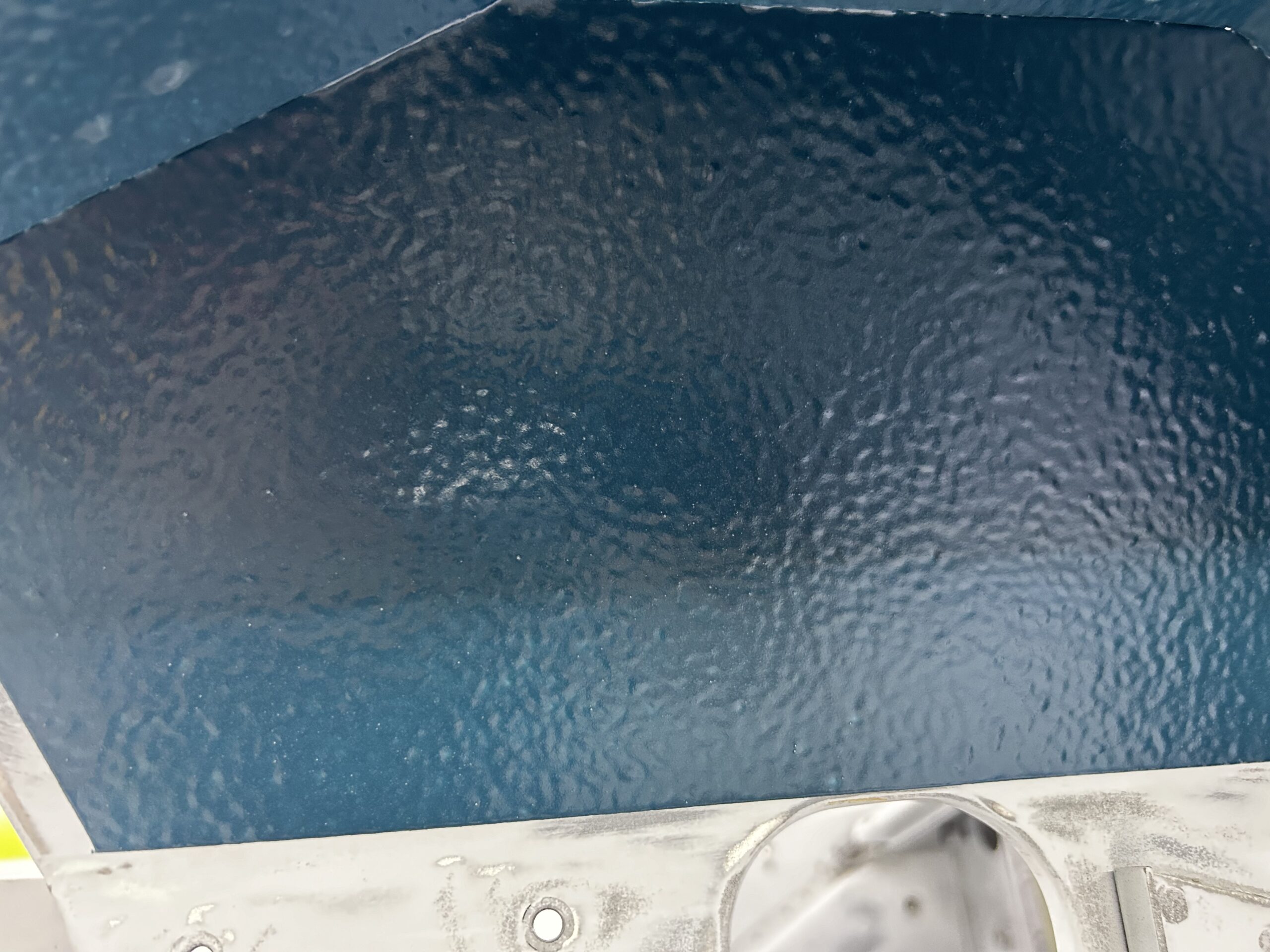
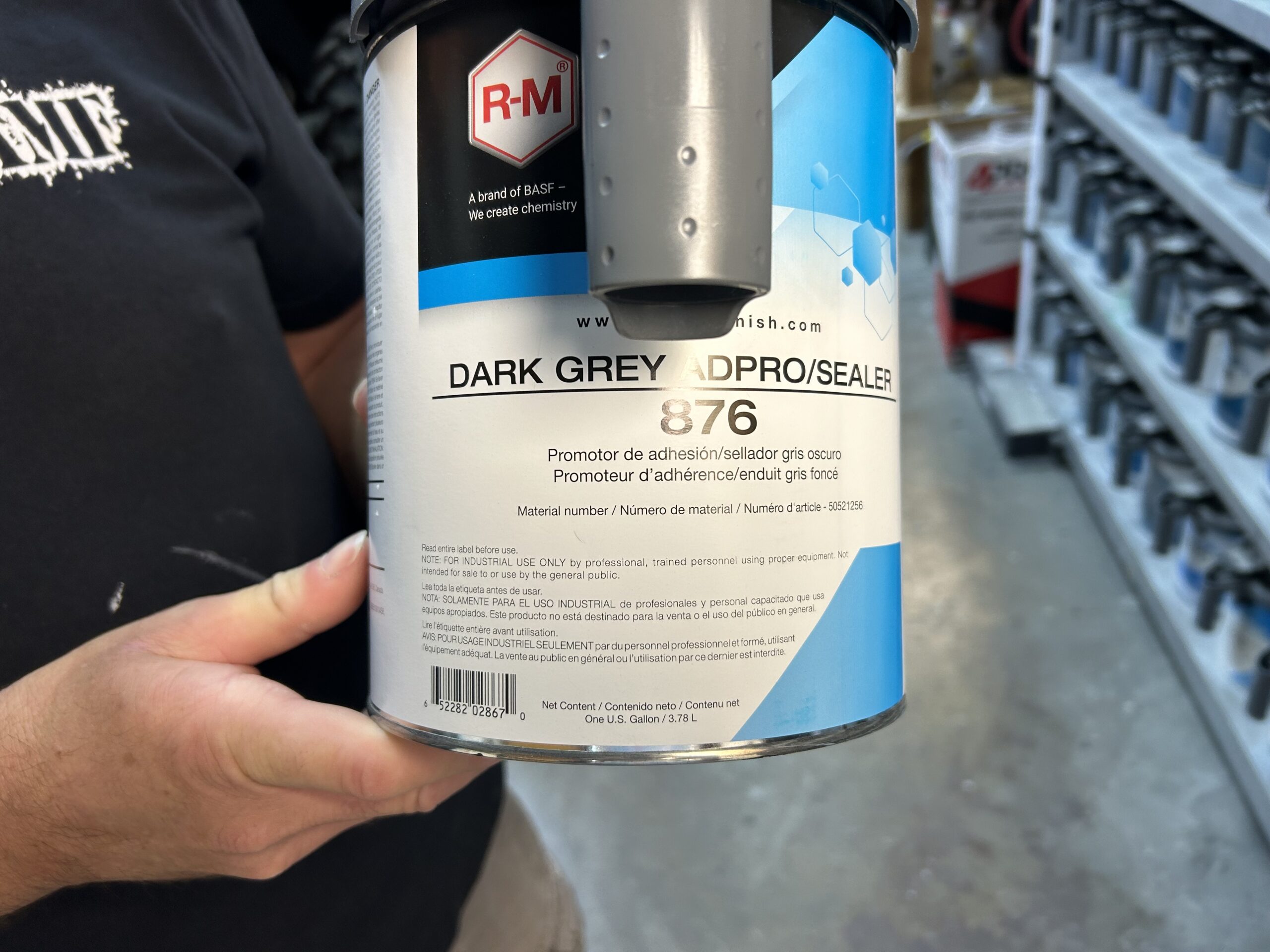
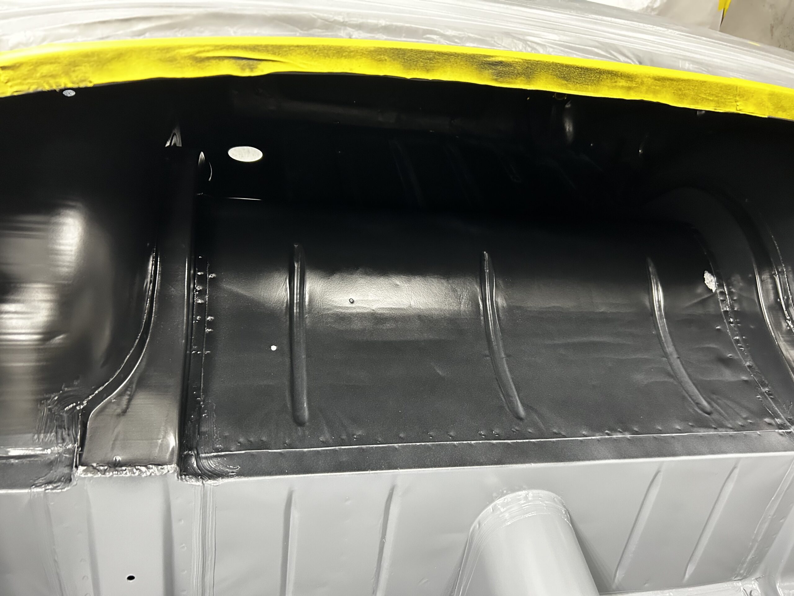
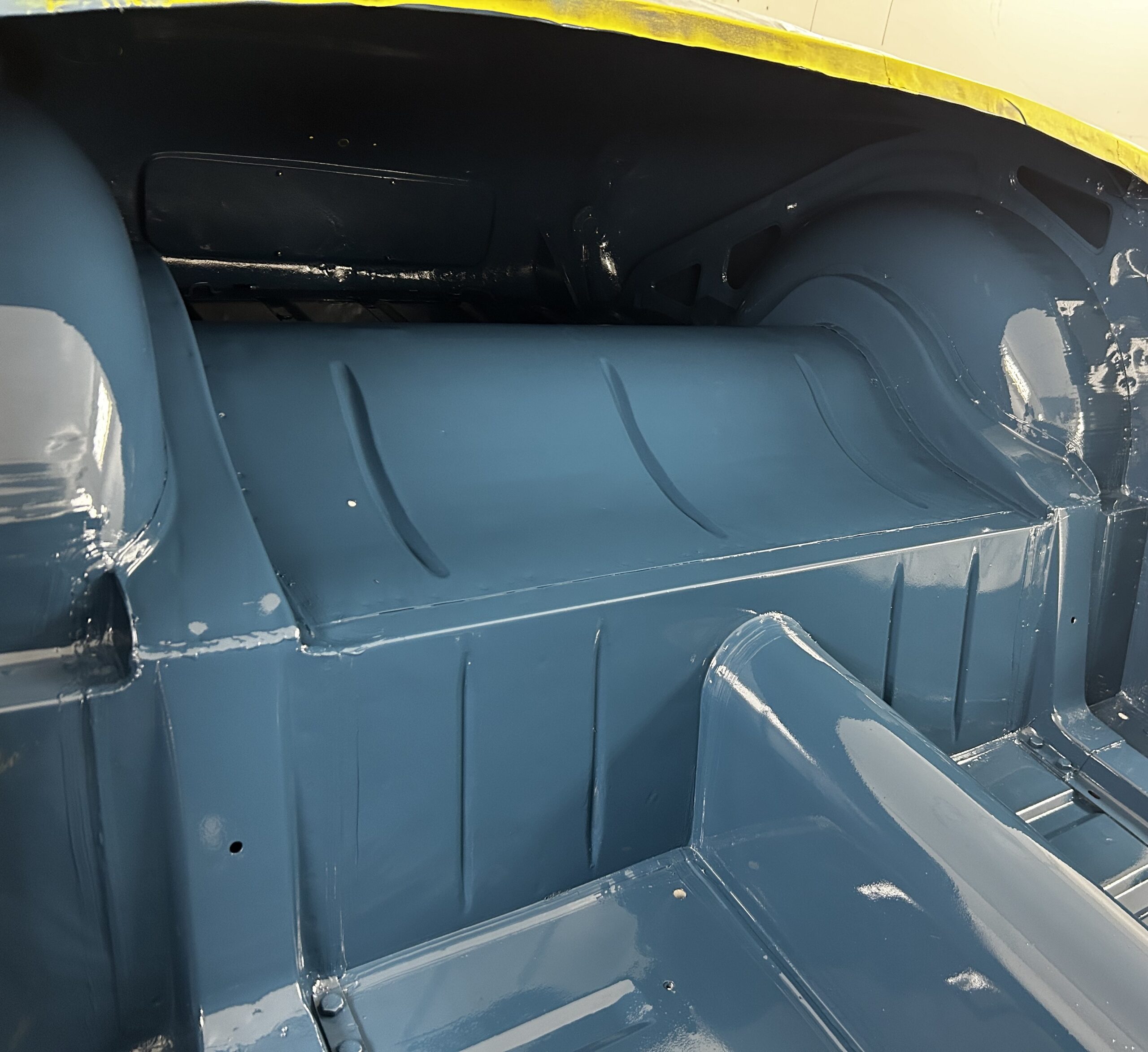
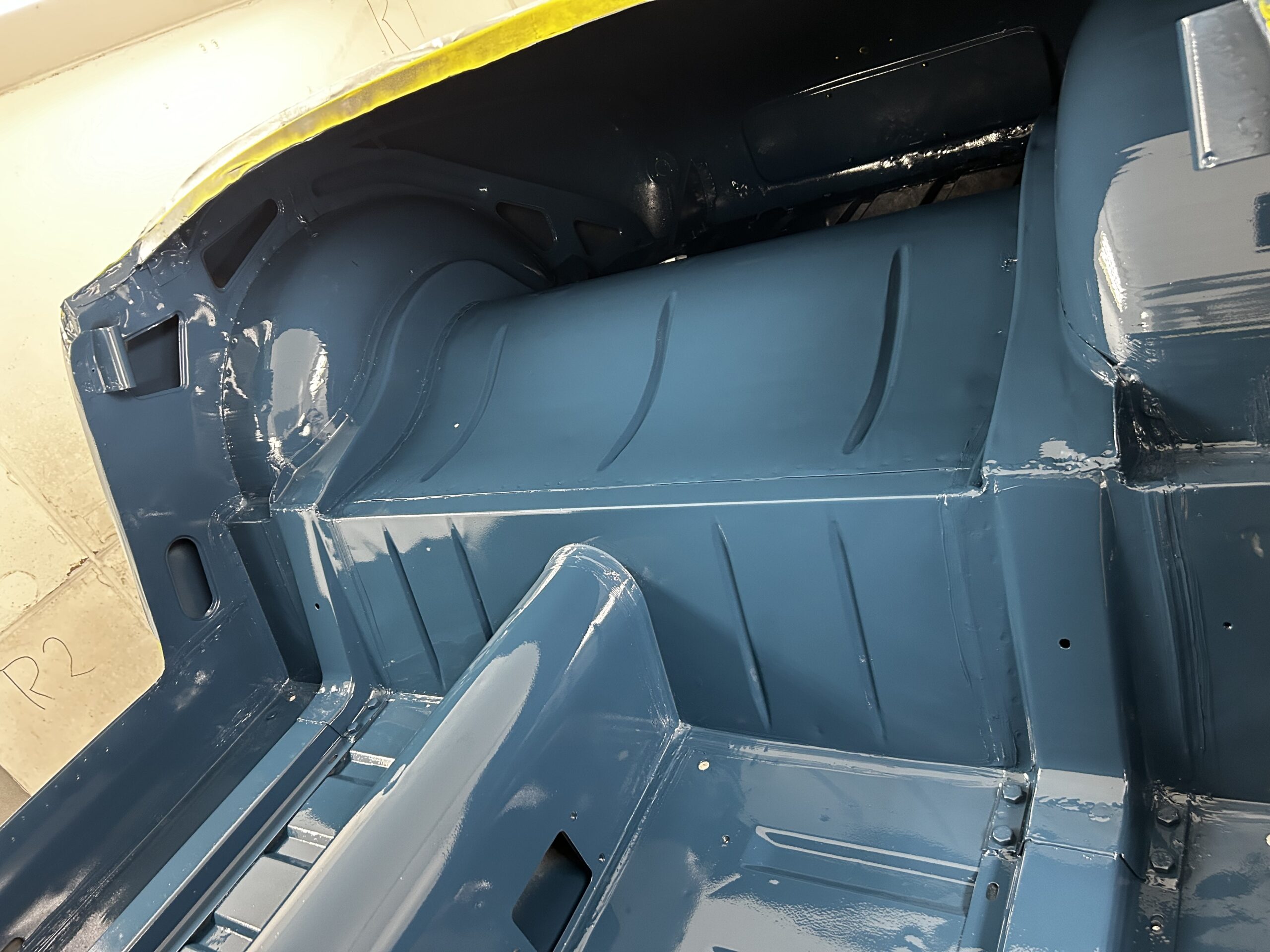
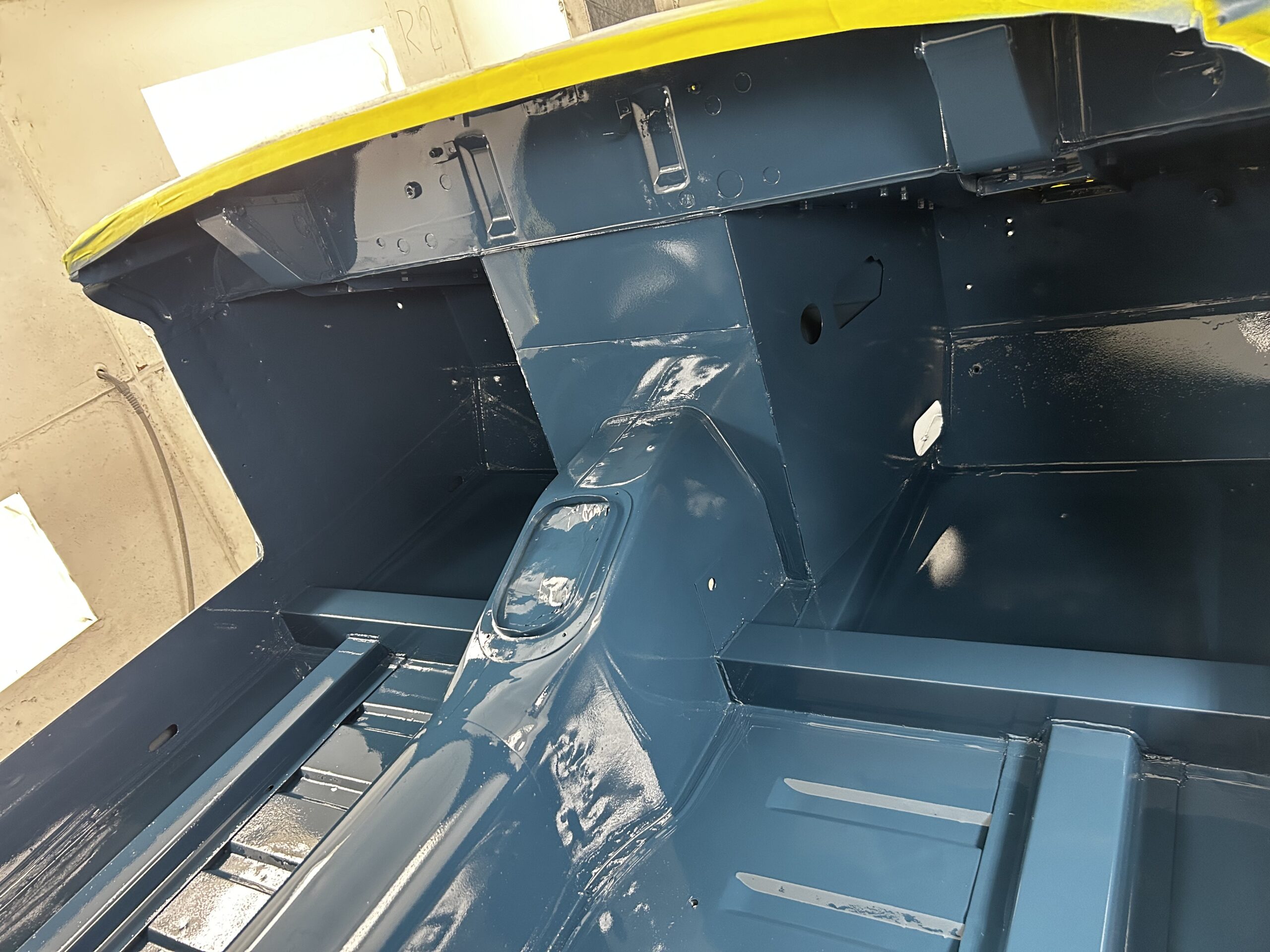
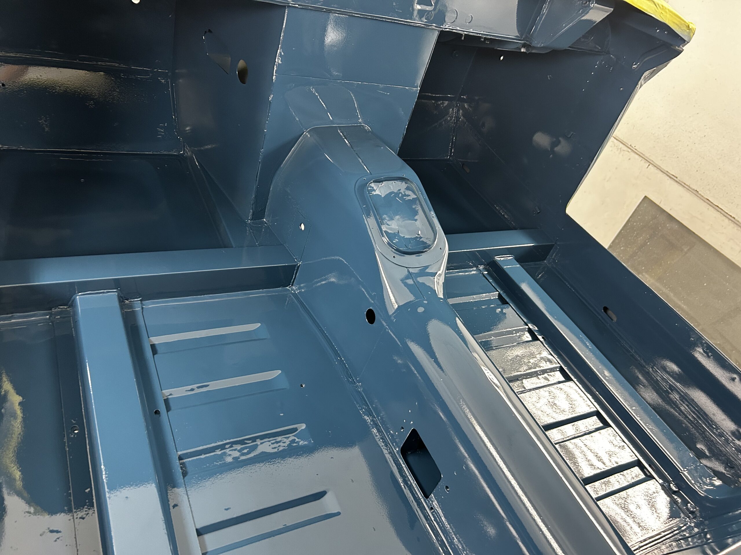
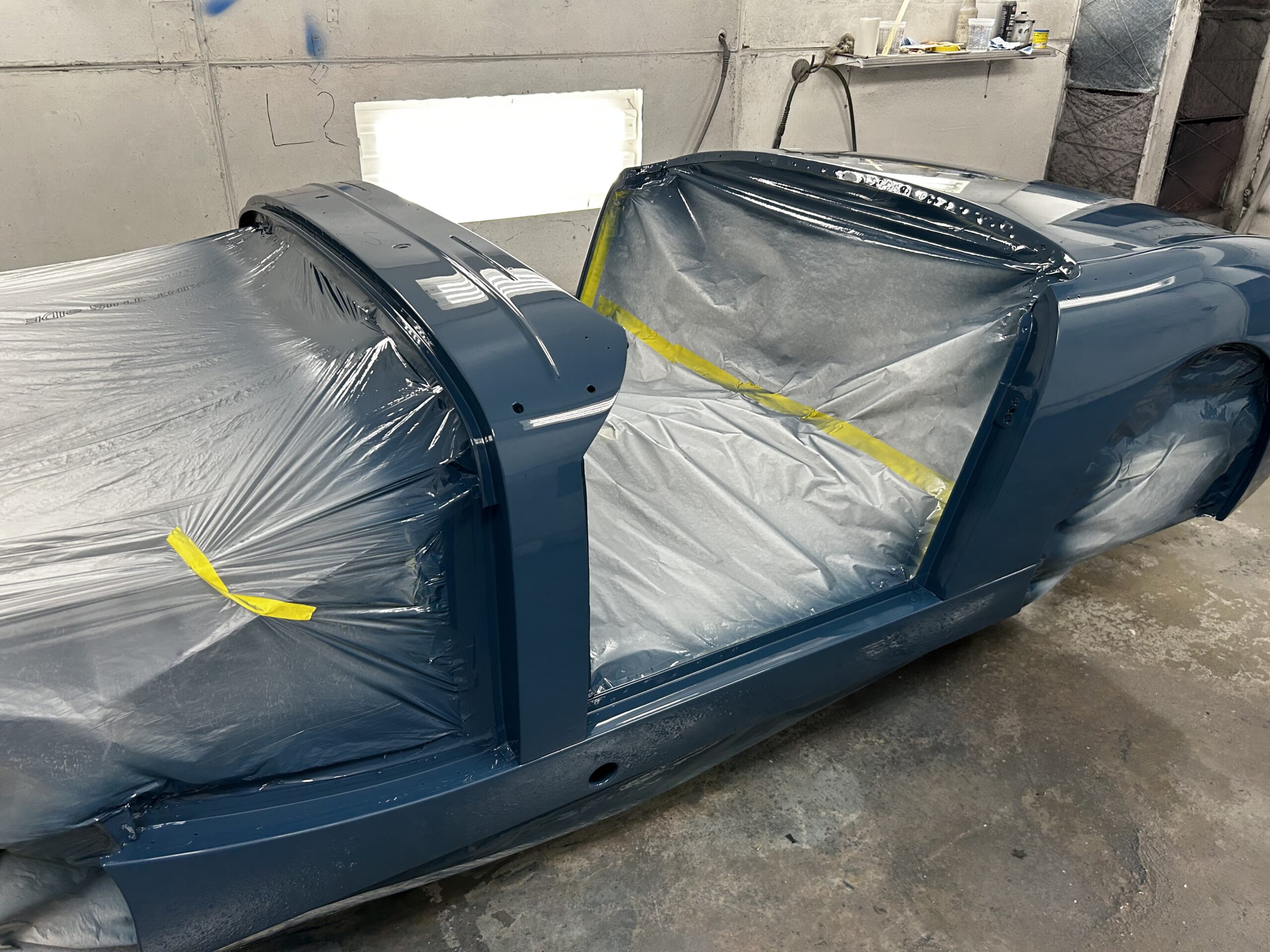
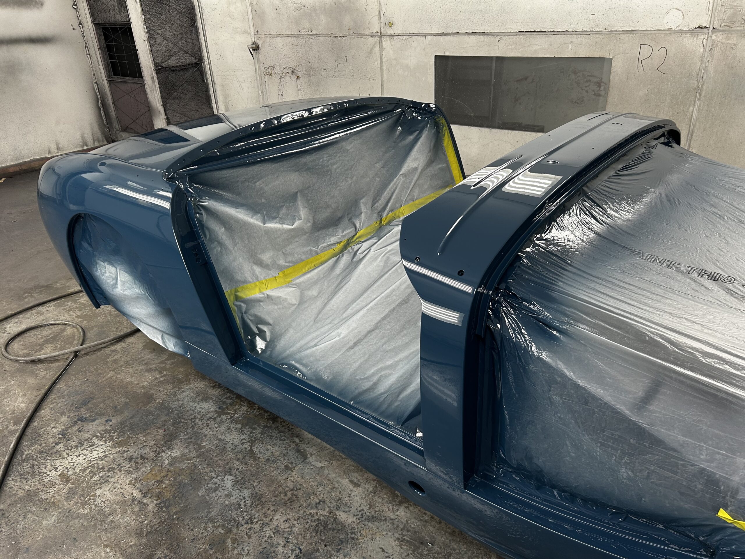
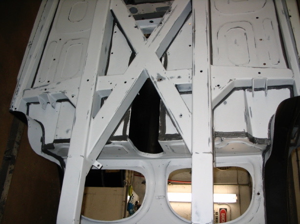
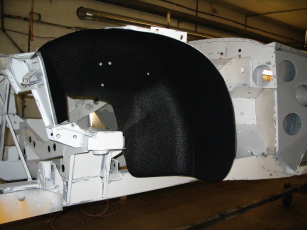
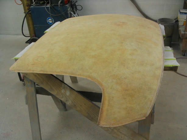
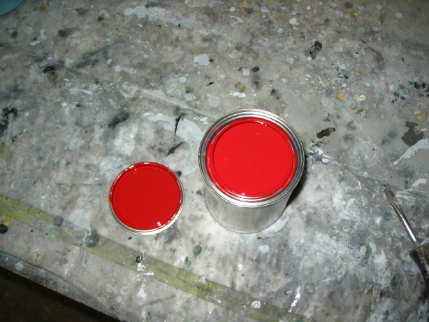
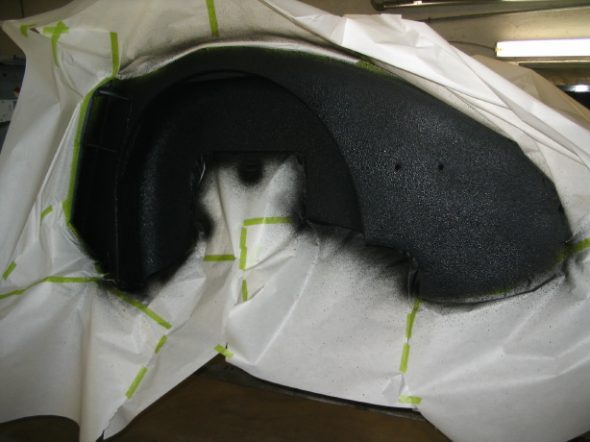
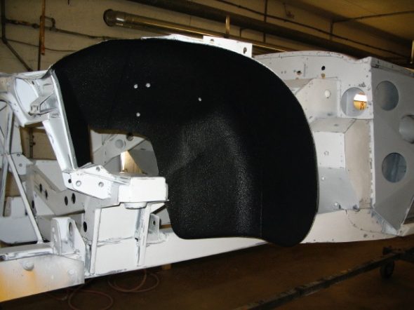
Chip Guard for the Wheels Wells – We decided to use a chip guard product in the wheel wells and will also use the same product under the front portion of the front shroud. It turned out very well, nice even coverage. The final red paint will then be sprayed over the chip guard so that it isn’t quite so obvious.
Chip Guard 1
Chip Guard 3
Chip Guard 4
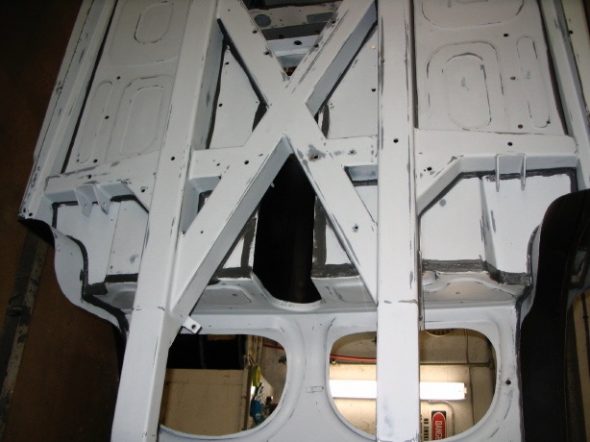
We also drilled access holes in the frame and outriggers and applied an etch primer as well as paint to protect against rust. I will need to decide if I will plug the holes or just leave them open.
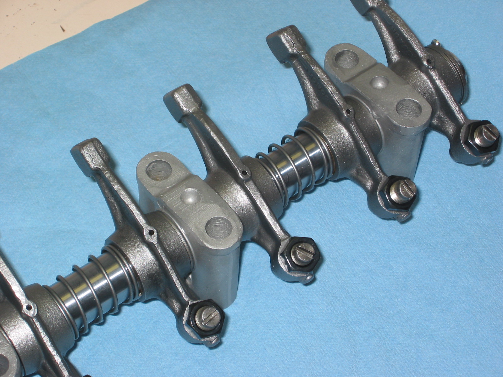
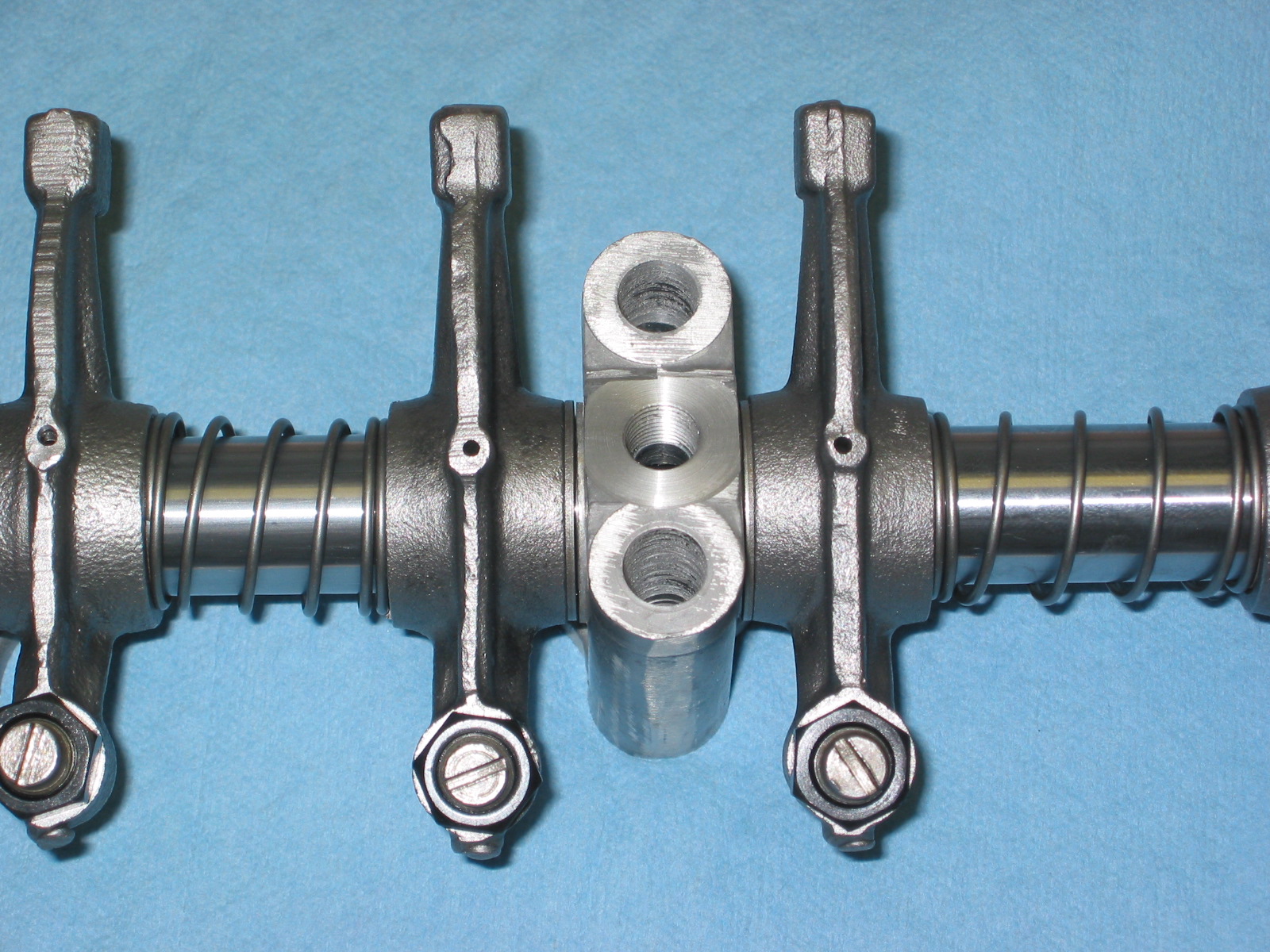
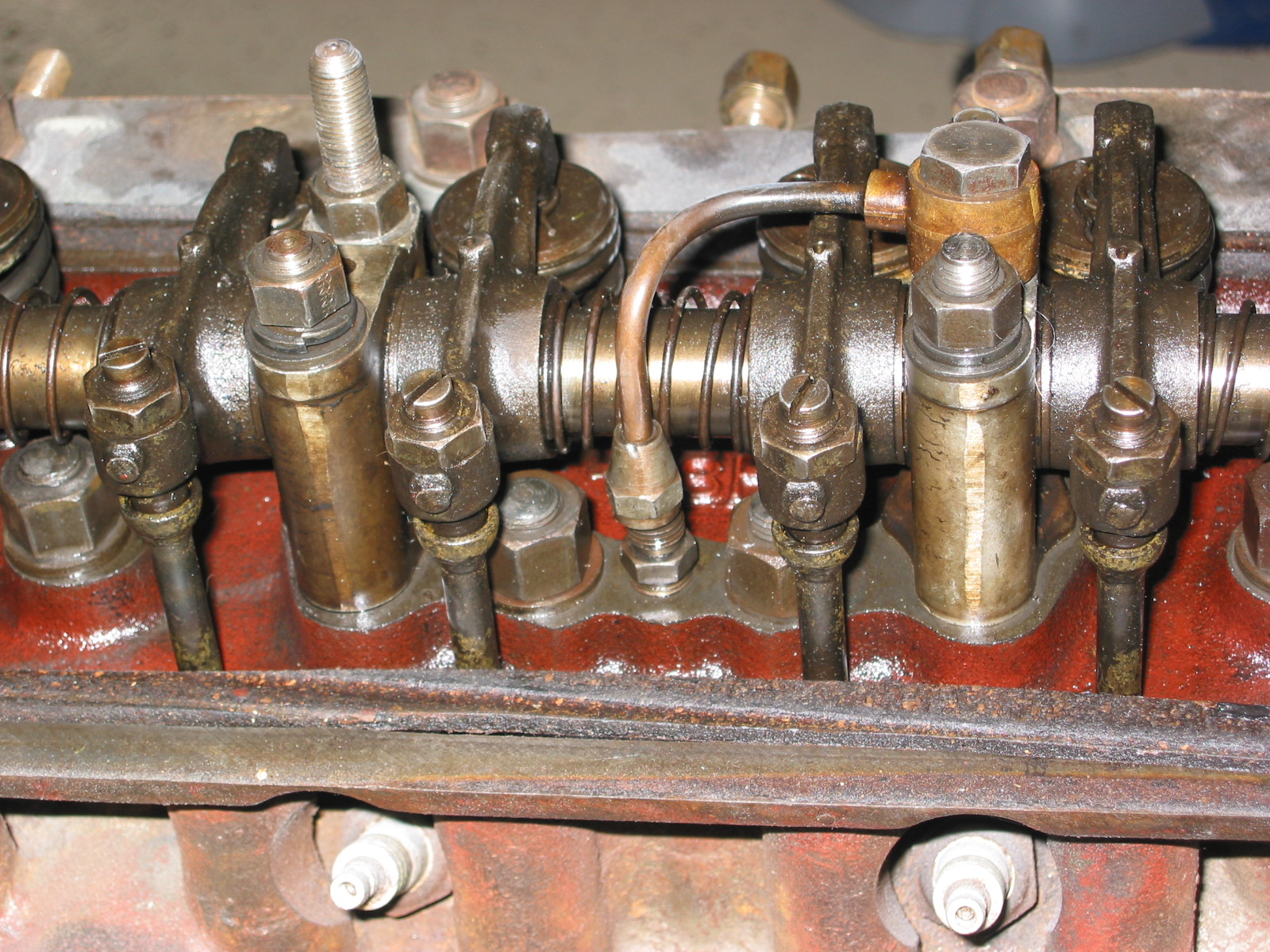
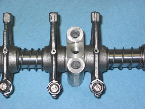
Engine Work Again – I received the rebuilt rocker arm assembly from The Rocker Arm Specialists and could not have been more pleased. The installed the new pedestal with the threads for the oil pipe and rebushed the whole mechanism. It looks great as well.

Rebuilt rocker assembly
Rebuilt rocker assembly
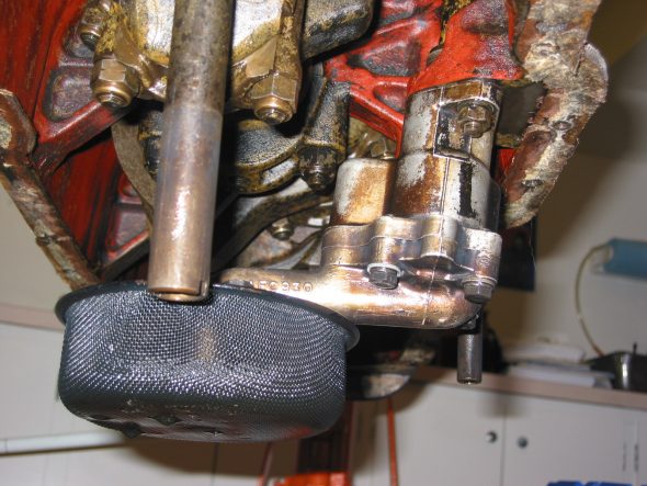
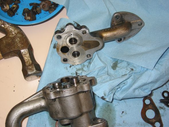
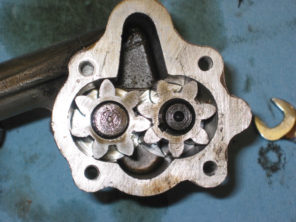
Oil Pump Removal and Inspection – After dropping the oil sump and cleaning it up a bit, I removed the oil pump to inspect it. I think I will go ahead and replace it to be on the safe side. It is the gear type pump, but others have recommended the rotary pump and since the fit is interchangeable, I think I will take their advice.
Oil Pump 5
Oil Pump 2
Oil Pump 8
Oil Pump 7