Introduction
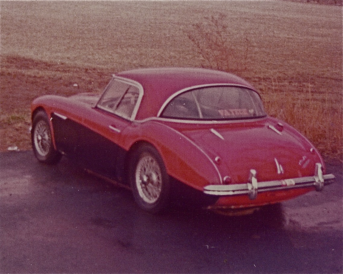
I took my Universal Laminations hardtop apart in 1977 and, of course, intended to completely restore it to original standard at the time. This did not happen and it sat disassembled until I began to undertake the complete restoration of my car in 2001. We all know that it is best to take things apart, document the process, photograph the components, and reassemble as soon as possible. C’est la vie!
While I did not have the benefit of disassembly notes and photos, I did have the article published by Roger Moment Healey Hardtop Repair comp in the Healey Chatter in June 1998, page 22-35, Bill Bolton’s kit instructions comp (I believe from Moss Motors, Inc, 1994?) that were provided with his hardtop restoration kit, and some very helpful notes and photos from John Homonek who restored his hardtop to a beautiful standard. These documents and images provided helpful guidance as I progressed through my hardtop assembly. Click Restoring a Healey hardtop for a pdf file of this web site.
I would have to say that restoring the hardtop was one of my least favorite tasks in my restoration of the Bloody Beast. Until you get the top together it really is a very delicate job. This summary has sixty-eight photos, all of which are good size, as I have intended this write-up to benefit others undertaking this job. I hope it proves helpful!
Conditioning the Parts for Assembly
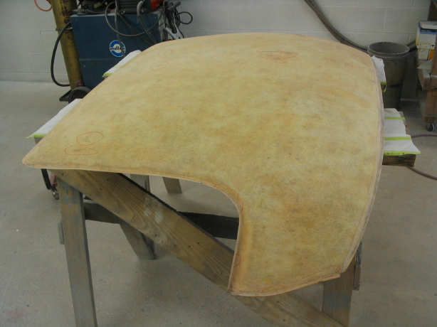
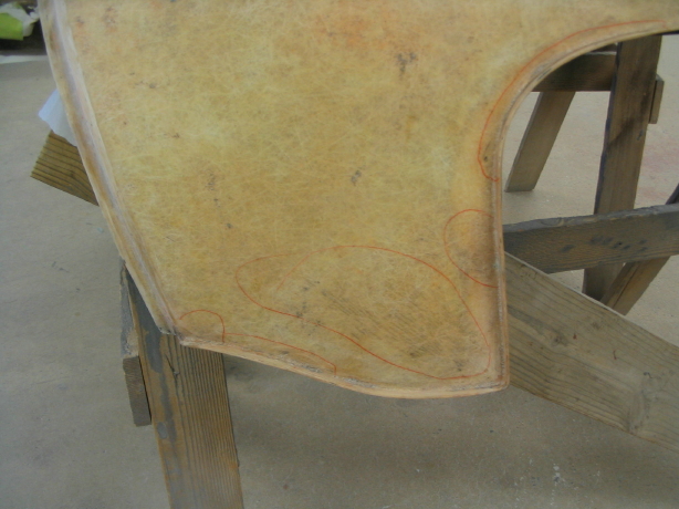
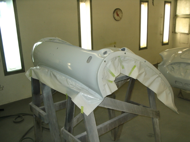
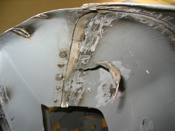
The fiberglass shell is very flimsy without the supporting aluminum hardware that serves as an external skeleton for the top. It had developed some cracks and blemishes over the years. These were patched first:

Hardtop Repair

Hardtop Repair
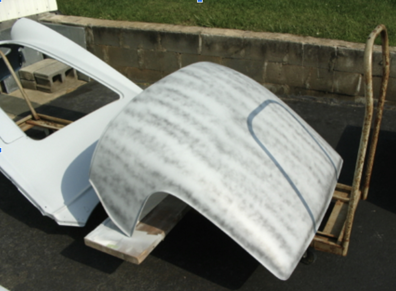
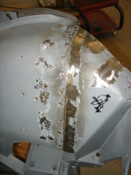
Then it was on to sanding and priming:

Sanding and Priming
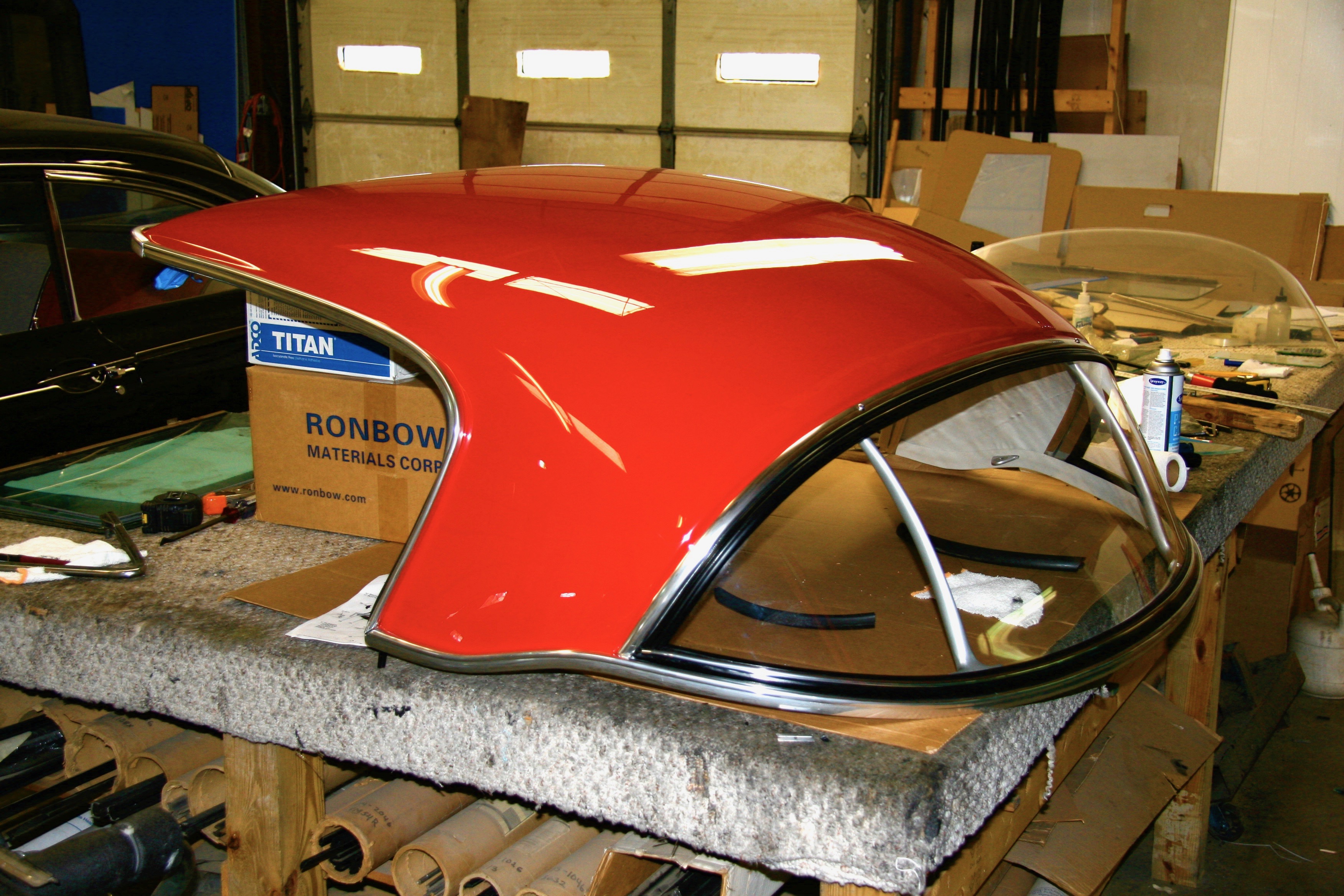
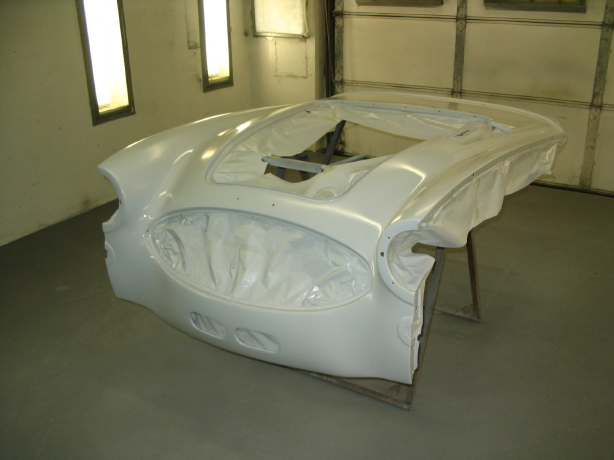
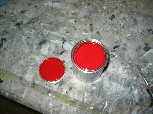
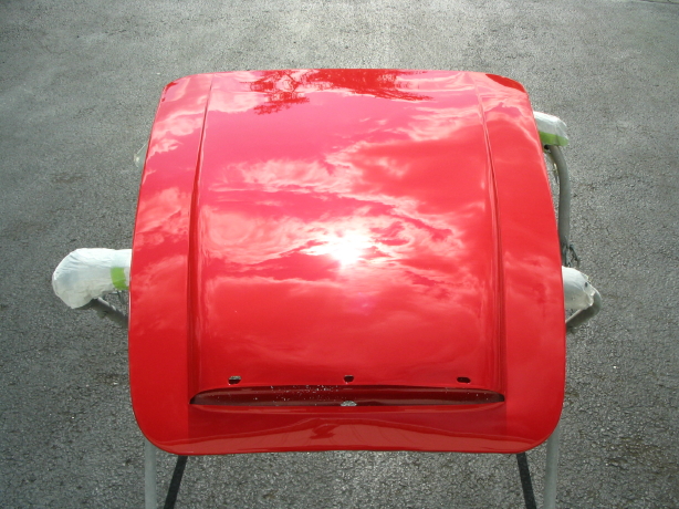
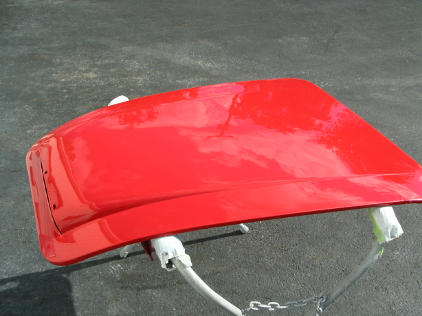
Followed by the application of Rosso Corsa Ferrari paint, and more sanding and polishing:

Hardtop painted
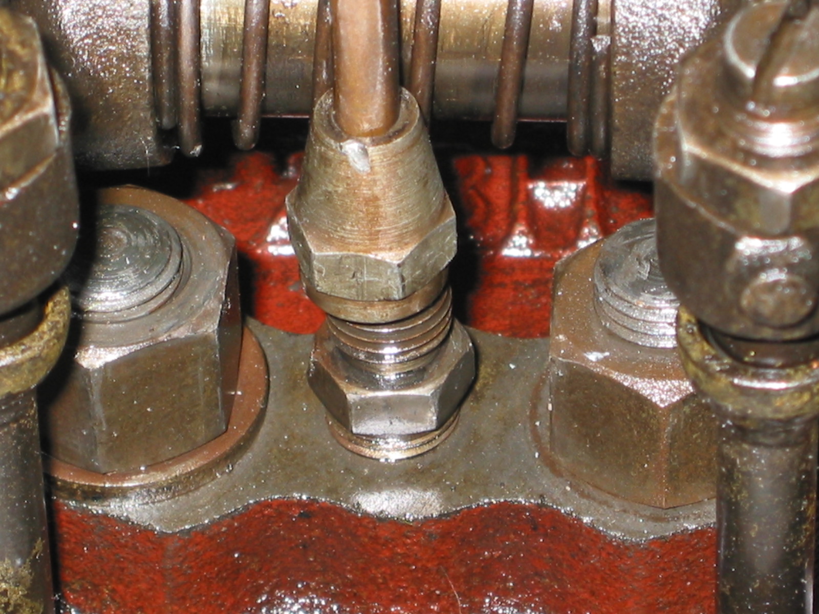
I cleaned up the aluminum frameworkas best I could including removing as much of the original clay/caulk/sealer that was possible from the mounting channels of the trim. The identification number for the hardtop and the assembly date is available on the right window cant rail.

Hardtop Serial Number
I then sent the aluminum off to Ano-brite ( I believe it is now named something else) in California for further cleaning and anodizing. Everything came back sparkling and looking almost new. In the meantime, I ordered Bill Bolton’s restoration kit that includes, headliner and trim fabric, rubber seals, foam pads, windlace, a new rear backlight and instructions. All high quality! Thanks, Bill.
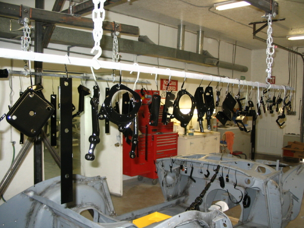
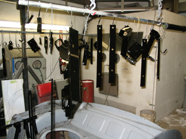
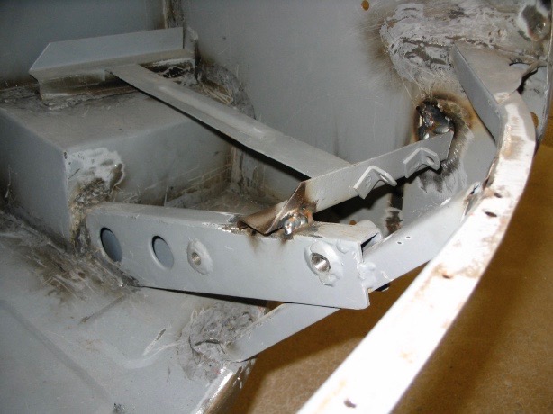
Cleaning up and refinishing several of the hardtop components was next on my list. The vertical rear aluminum braces and the front corner brackets were sanded and painted a dull aluminum that closely matched the original color.

Hardtop Braces

Hardtop Front Brackets
The rear mounting hook/plate/wing nut assembly was also in good shape but I did decide to replace the hooks and again sourced them from Cape International. I ordered new mounting plates, but like the shape of the originals so I will stick with them.

Hardtop J Hooks
The steel locating spigots just needed some cleaning up and painting. They were painted black and new truss head stainless screws were purchased for assembly.

Locating Spigots
The headliner was torn and dirty and needed to be replaced. The headliner frame needed attention, too. It was a little rusty and the felt was in bad shape. The frame was painted black and new felt was glued in place.

Headliner old – on frame

Headliner-old-on-frame

Headliner-old-on-frame

Headliner Frame Restored

Headliner frame new felt
I was surprised to find the foam of the front pad in excellent condition after removing the headliner fabric. I don’t know Italian, but it appears that the Dunlop foam rubber was manufactured (or at least the pad was) in Italy.

Headliner Front Pad

Headliner Front Pad
Hardtop Assembly
After getting all components in good shape or purchasing new bits, it was time to begin assembly. The first task was to glue the fabric to the bottom cant rail.

Fabric on Cant Rail
The I glued the fabric to the inside corners of the top shell.

Hardtop Corner Fabric
Followed by glueing the carpet felt to four locations on the underside of the hardtop shell. This buffers the headliner metal frame from the fiberglass shell.

Hardtop Carpet Cushion for Headliner Rails
Then applied 3M Body caulk (dum-dum) to the channel in the front rail and pushed it onto the front lip of top shell.

Installing Front Trim
Applied 3M caulk to the channels of the side cant rails and pushed the rails onto the top shell. Temporarily screwing in the corner braces and the small aluminum plates helped pull the side rails into place.

Front Joiner Plate
The original wood braces that mount on the side cant rails were rotten. I had new braces made to original specifications. These were screwed to the side rails with two truss head stainless screws.

Wood Side Rail
With the top upside down, the locating spigot pins were dropped into place, but not secured until after the bottom cant rail was pushed onto the top shell.

Steel Spigot Installed
Applied 3M caulk to the channels in the bottom cant rail and positioned the rail on the top shell. This job requires two people! After properly aligning the rail, six stainless truss head screws can be screwed into place through the side and bottom cant rails into the steel spigot pin.
Applied a thin coating of the 3M caulk to the channel in the aluminum trim for the top of the backlight and pressed it onto the top shell. Again, two people really help with this task.
I then used a block of wood on each side of the top to spread the top toward the outside of the bottom cant rail and inserted two #10 stainless truss head machine screws with washers and nuts to link the bottom cant rail to the backlight top aluminum trim. After tightening the fasteners the wood spacer blocks were removed.

Spacer Block

Mounting Plate
I had saved the five small original rubber seal pieces that were used as spacers/cushions between the headliner and the upper backlight aluminum trim. These were glued in place at the same locations on the inside of the top shell.
Bill Bolton’s kit included 4 small blocks of foam padding (two on each side) that I glued to the interior sides of the top shell. These pads are used to force the upholstered quarter panels against the side and bottom cant rails. The original part number for theses pads is 27H9592. Again, I could see where these pads were glued to the shell originally and they were cemented to the same locations.

Backlight Rails in Place

Foam Quarterpanel Cushions
The headliner frame with new fabric supplied by Bill Bolton and sewn to the frame by a local shop, Classic Upholstery, was then inserted through the backlight opening and pushed into place. The metal clips at the front of the headliner were pushed under the front aluminum rail, and the rear edge of the headliner was pushed in place between the backlight upper aluminum trim and the rubber cushions that had been glued to the the shell.

Inserting Headliner

Inserting Headliner
The aluminum backlight braces were then installed. I stuck 3M body caulk under the heads of the two chrome machine screws that went through the backlight upper aluminum trim and into the braces to help seal out water.

Backlight Support Braces

Front Pad in Place
I was then able to flip the top over and install the front pad. The screws that fasten the front side braces needed to be withdrawn so that the triangular clip on the side of the front pad could be pushed into place between the two screw locations. The screws were then replaced. The front rail header seal, part number 27H9597, was then cut to fit and glued onto the rear edge of the front aluminum rail.
The rubber seals for the side rails were also trimmed and lightly glued in place. The windlace supplied by Bill Bolton was then pushed over the rubber seals and onto the side and front cant rail lips to create a nice finished look. One continuous piece of windlace was used to cover the rails. It is somewhat difficult to push it into place in the 90 degree corners. The front clasps were then screwed into the front corner brackets. I have these set as they were originally, but I expect the “J” hooks will need some adjustment when the top is put in place.

Windlace

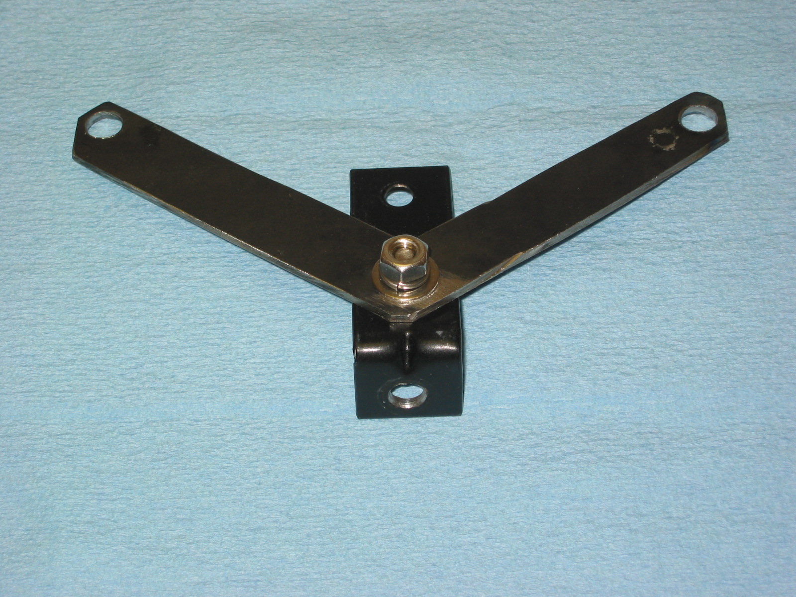
Hold Down Tab Bracket
The hold down brackets that, along with large “J” hooks, clamp the hardtop to the cockpit were then inserted through the slots in the bottom cant rail and secured with two #10 truss head machine screws. I used the original quarter panel boards and recovered them with the headliner material. They were pushed into place and wrinkles were “massaged” out as much as possible.

Hold Down Tab Bracket
Plexiglass Backlight Installation
I may have been able to install the backlight myself, but after studying it a while, I decided to take the job to a local glass installation shop that had previously assembled my windscreen. I was glad that I did, because the plexiglass needed trimming to fit and the shop got the job done much more quickly than I would have fumbling along in my trial-and-error manner. The images below might help others who decide to undertake the task themselves.
I managed to get the top to the glass shop without damaging it! The owner reviewed the plexiglass, the seals and proclaimed himself ready for the task.

At The Glass Shop
To get a feel for how the top and bottom seals would ultimately join together the installer slid the pieces together on the rails. The upper backlight glazing rubber was part number 27H9594. The lower glazing seal was part number 27H9595.

Fitting the Corner
The iterative process of trimming both pieces began until he was eventually satisfied that the fit was as good as it was going to be. Of course, the second side, in this case the LH side was more difficult to fit. The key is to trim only a little at a time. You can always trim more, but if you go to far there is no recovering!

Fitting the Corner
The installer used a silicon spray to temporarily soften and lubricate the rubber to make it easier to fit the plexiglass and the locking seal. Unfortunately, we discovered that my glass was not shaped properly.

Silicone Spray
I was able to compare it to my “foggy” original and one could see that trimming was required. As with the rubber, the rule was “a little at a time.” We taped the glass to mark the material to be removed and to avoid scratching it and then used a belt sander to gradually remove material. We repeated this process three times until satisfied with the fit.

Trimming the Backlight

Trimming the Backlight

Protecting the Backlight

Trimming the Backlight
We experienced a little problem with the lower locking strip – it just did not want to “lock” on the bottom edge of the strip. The shop had another, slightly larger, strip that worked, but it had a chrome finish. I will paint the chrome a matte black to look just like the rubber. The plastic tool in John’s hand is known as a “bone.”

Fitting Backlight
These are a few images of the locking strip being “run in” to the larger seal. As always, the right tool for the job is key. John’s assistant trimmed the locking strip to the proper length.

Installing Locking Strip

Installing Locking Strip
After installing the locking strips and cleaning up the silicone spray residue, the backlight installation was complete. Now, it is back home to put the seals on the bottom cant rail.

Finished Job

Finished Job
I believe the original spigot pin pad was 5” x 1/2” x 1 1/8” (27H9599). I did not have a replacement pad that met original specs, but I used 2 pieces of weatherstripping on each side that were 5” x 1/4” x 1 1/4”. These pads were punched for the spigot pin and then glued together to make a pad similar to the original.

Spigot Pin Pad
The narrow (3/4”) packing strip for the bottom cant rail (27H9686), was then glued into place. The piece in the image below was cut off to butt against the spigot pin pad.

Small Rubber Packing Strip

Small Rubber Packing Strip
The wide (1 1/8”) packing strip, to the left in the image below, was glued over the narrow packing strip and it also was run to the back of the spigot pin pad. Then the header rail seal (27H9597) was lightly glued over the edge of the bottom rail and the windlace was pressed over it and the rail to give a finished appearance.

Seals and windlace
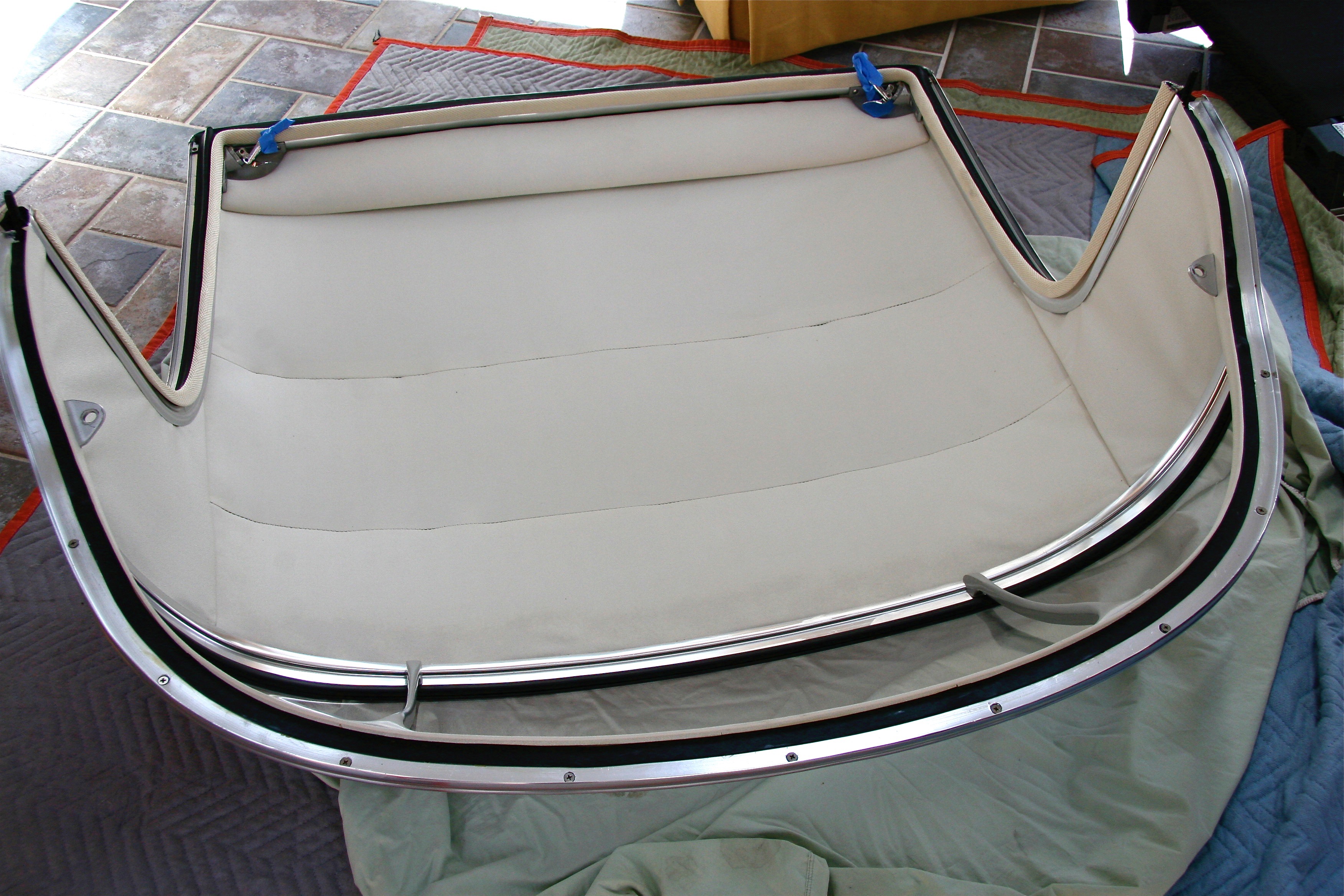
The finished job is seen in the images below. There were several things that could have been done a bit better, but isn’t that always the case with the first time you do something? I was generally pleased with the results.

Lower Windlace

Lower Windlace

Headliner & Windlace

Headliner & Windlace
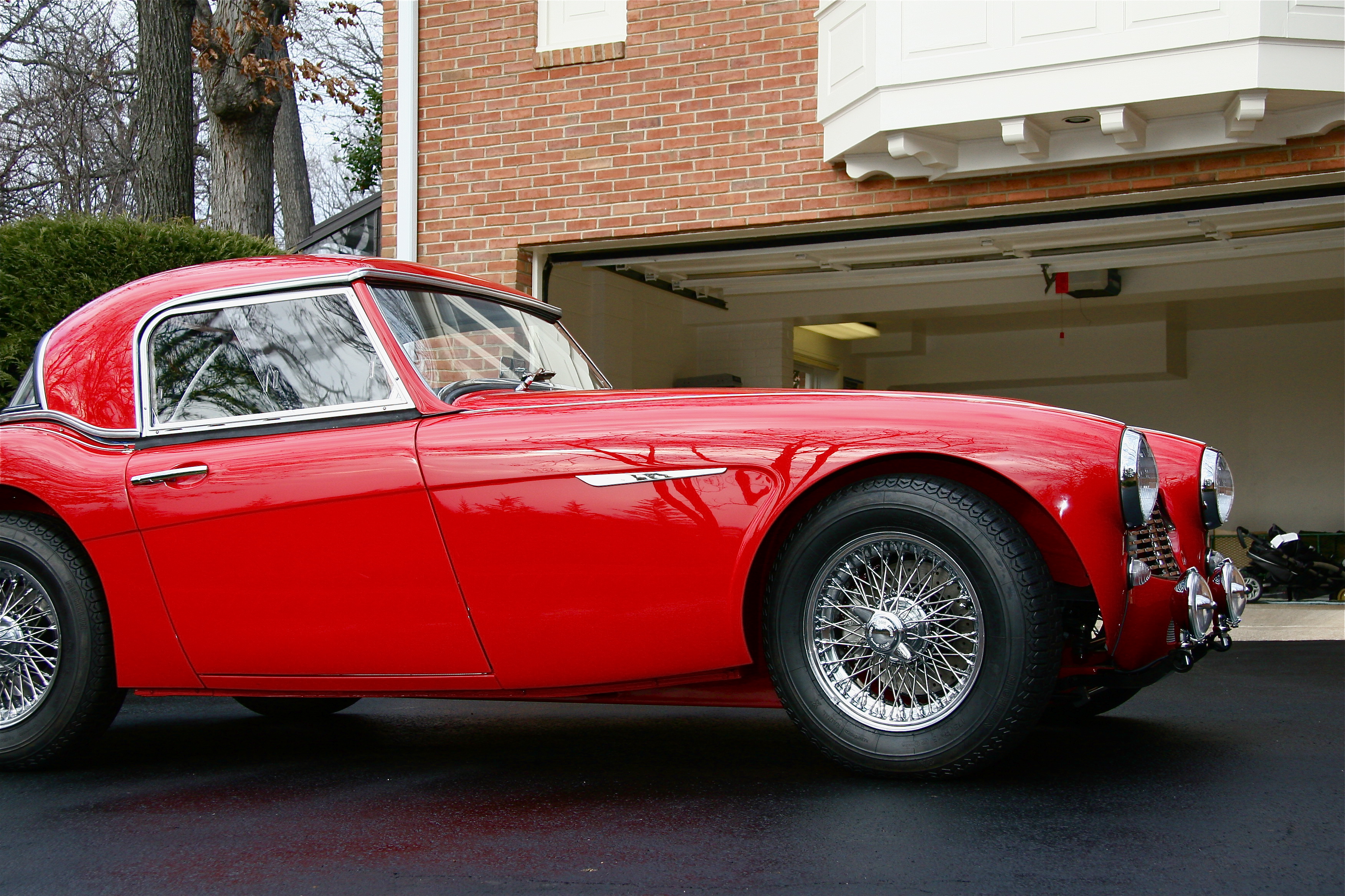
These are some images of the top on my car. It took some time to get the top to fit well with the cockpit molding. I still have a slightly larger gap at the top quarter panels than I want so I will continue to try to refine my fitting.

Hardtop


Hardtop

Hardtop
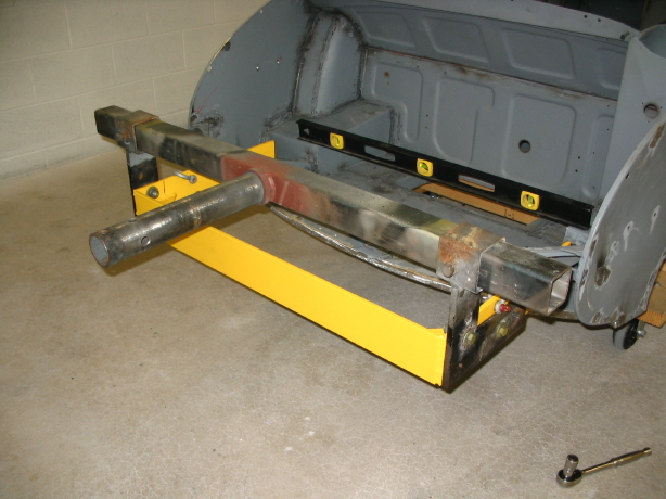
Storing The Hardtop
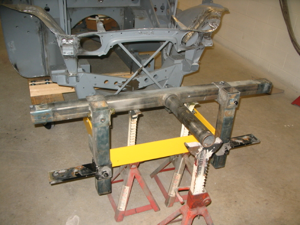
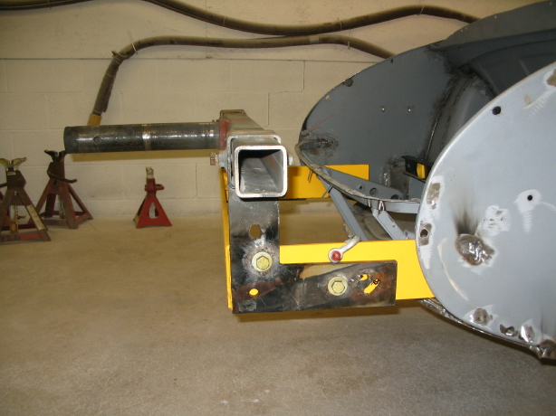
While I love my hardtop, Healeys were meant to be driven with the top down or off. That means storing the hardtop out of the way and where it will not be damaged. I am sorry that I don’t recall the source of these images, but they illustrate a homemade wall mount that would appear to be very effective. I may build this mount, but have not done so yet. I did order a cover and rolling stand for my hardtop from California Car Cover. Both are working quite well for the moment.

Hardtop Wall Mount Image 1

Hardtop Wall Mount Image 2
Hardtop Cover pdf:

Hardtop Cover PDF
http://www.calcarcover.com/product.aspx?id=1037
John Spaur at jmsdarch@sbcglobal.net built an overhead hoist for his top for about $50.00.
This is another hoist plan that was put together for Jeep Hardtops. It includes a list of materials needed:
http://www.jk-forum.com/forums/jk-write-ups-39/hardtop-hoist-storage-write-up-5559/
and a pdf file of the same:
Hardtop hoist:storage write-up
And, this is yet another overhead hoist that can be purchased for installation in one’s garage:
http://www.top-hoist.com/index.html
and a pdf file of the same:
Top-Hoist.com — manual and electric hoist lifts for your convertible hardtop
zz