I noticed a very slight wobble in the shaft of the water pump that was ascertained when holding the fan at opposing sides and shaking. Since I am I the midst of a ten-year renewal I decided to go ahead and replace much of the cooling system to include the water pump, mechanical fan, the thermostat and gasket, both radiator hoses, the fan belt and the coolant.
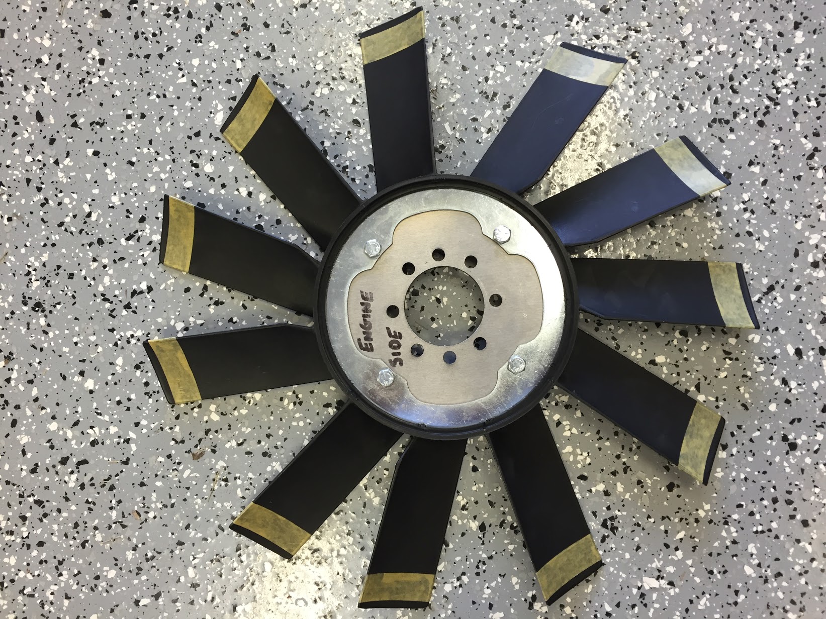
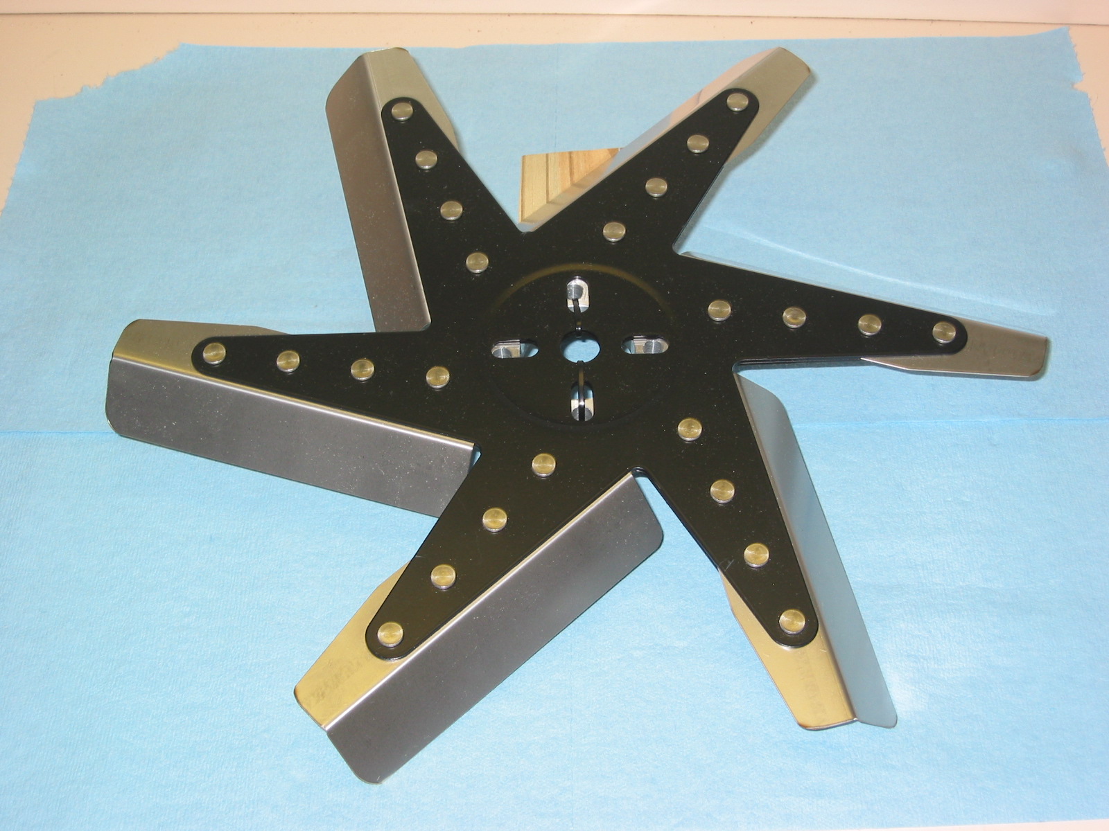
When I restored my car I installed the stainless steel flex fan sold by British Car Specialists. It seemed to work quite well, but was pretty noisy. I noticed that AH Spares was marketing a yellow asymmetrical plastic fan similar to the “Texas Cooler” fan which so many owners seem to favor.
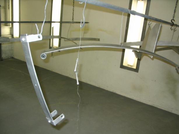
Stainless Fan
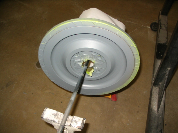
AH Spares Fan
The water pump to be replaced on my car is not the original pump. I am really not sure who produced the pump I used when I restored my car. It does not have any external markings on the pump body. Michael Salter restores original pumps but does not want to deal with replacements so I purchased a newly produced pump marketed by AH Spares which is claimed to be superior to what is commonly available on the market. The pump, as unwrapped, is painted black so I roughed up the painted surface, taped off the vent holes and painted the pump and pulley “Healey Green.” A gasket is applied with the pump. I also ordered new water pump/engine block studs to install.

AH Spares Water Pump, Gasket, and Studs
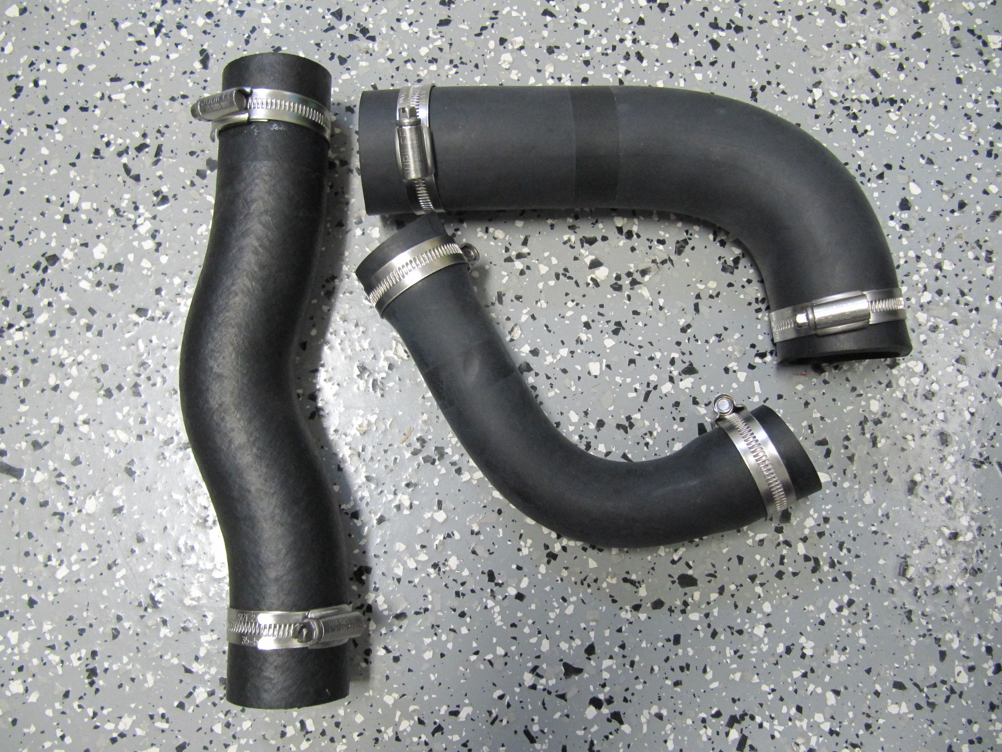
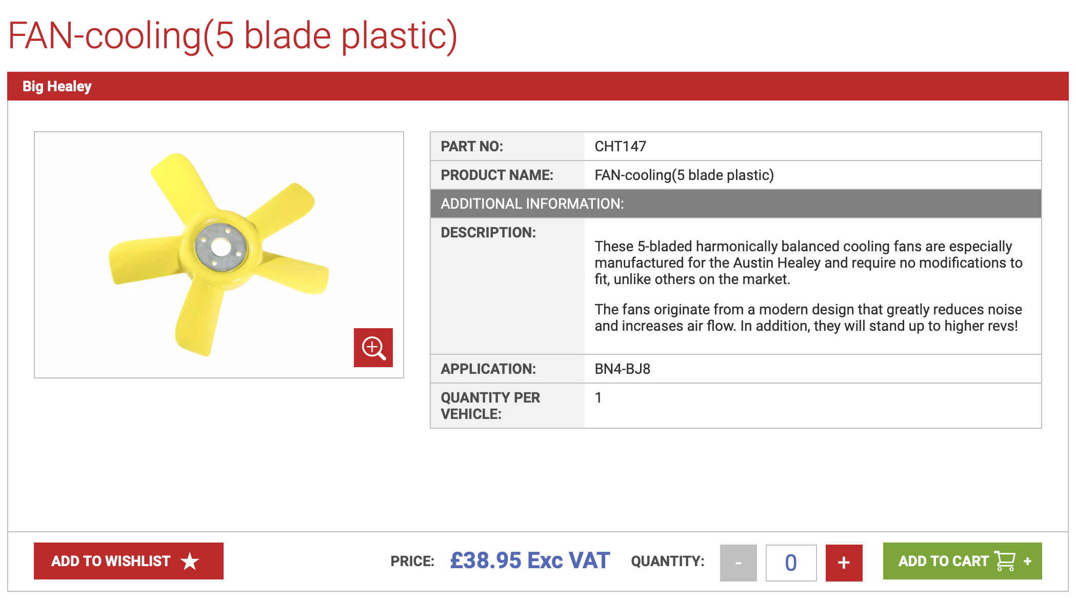
I chose to replace both radiator hoses with Kevlar hoses from AH Spares. The bottom, or lower, Hose has a provision for the heater pipe.

AH Spares Kevlar Upper Radiator Hose
AH Spares Kevlar Lower Radiator Hose With Heater Port
The fan belt is an odd size attributable to the addition of the Delco alternator, but I found one through Amazon from an outfit called Global Power. The belt is a “V” belt 3/8″ x 43.”

Global Power V-belt 3/8 x 43″
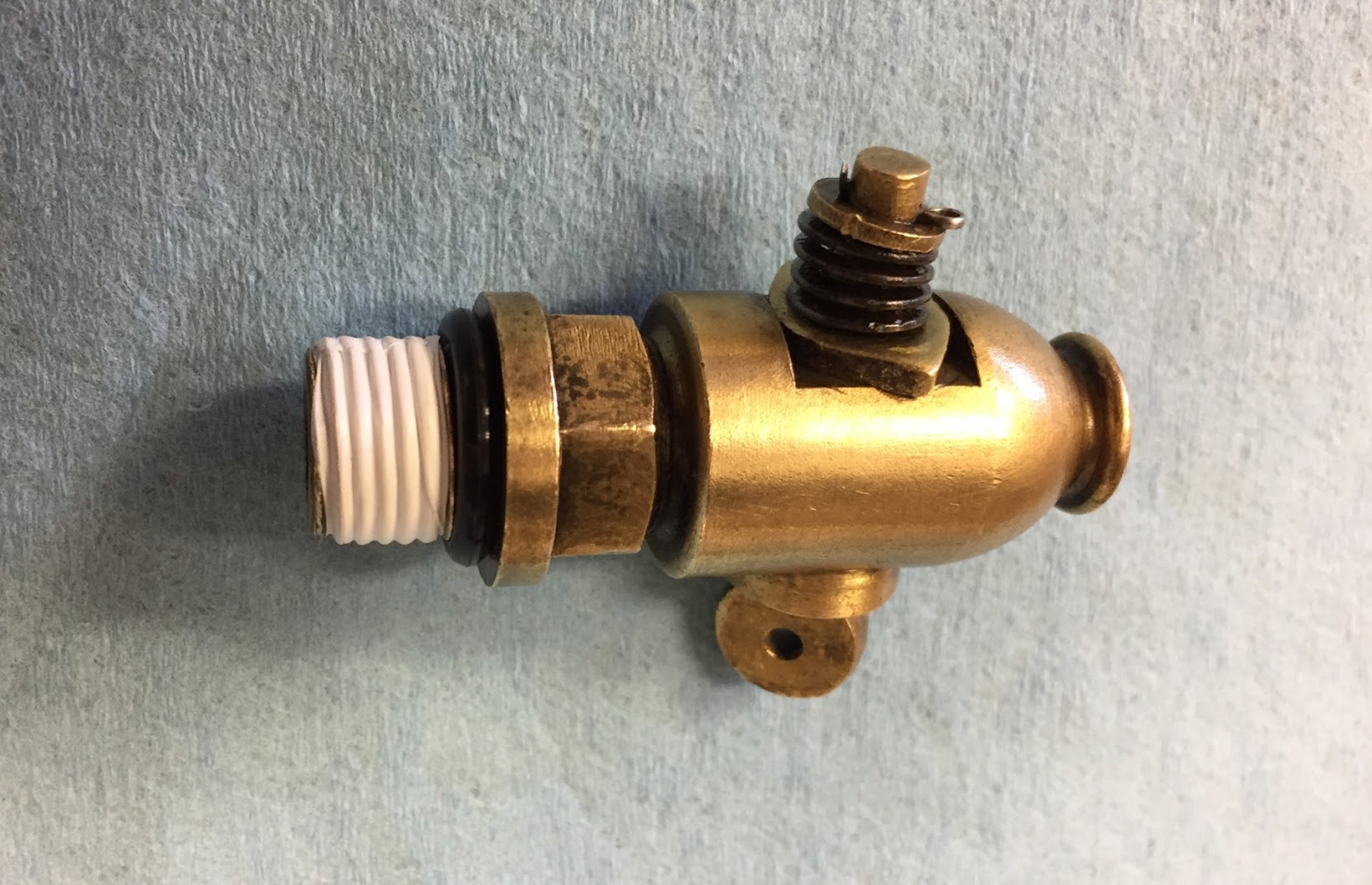
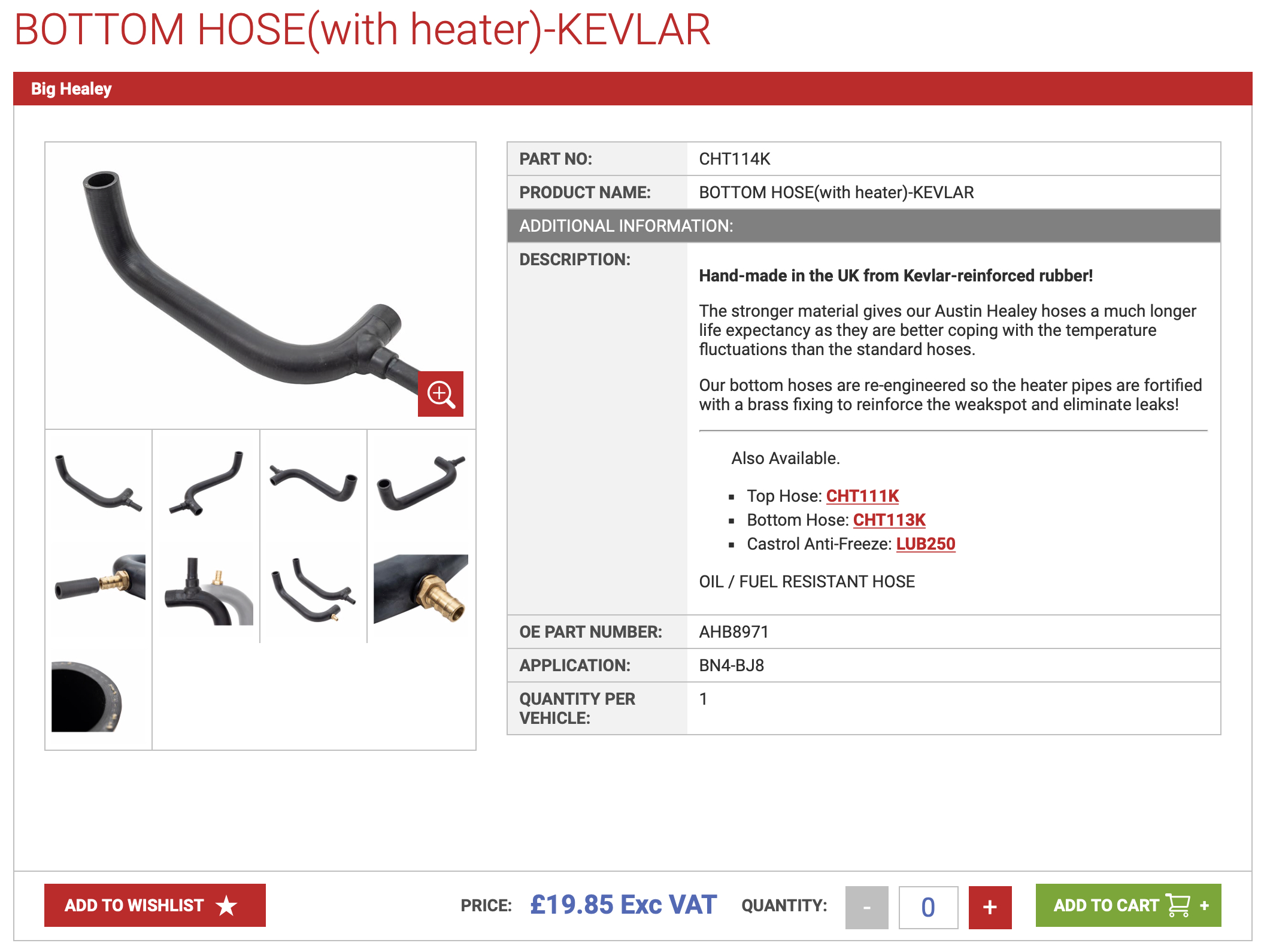
Finally the thermostat. Having lived in Virginia with considerably cooler winter temperatures than Florida, I had been using a 195 degree thermostat. I took this occasion to switch to a sleeved 160 degree unit supplied by David Nock at British Car Specialists.
British Car Specialists Thermostat
That concludes the list of parts used on this project. Now to the removal of the old and the installation of the new!
My first step is to remove the stainless panel between the shroud and the radiator. This requires loosening the top radiator mount bolts so the radiator can be pushed rearward slightly. Then disconnect the bonnet pull rod by pulling out the split pin, followed by the four stainless self-tappers.
Radiator Front Stainless Panel
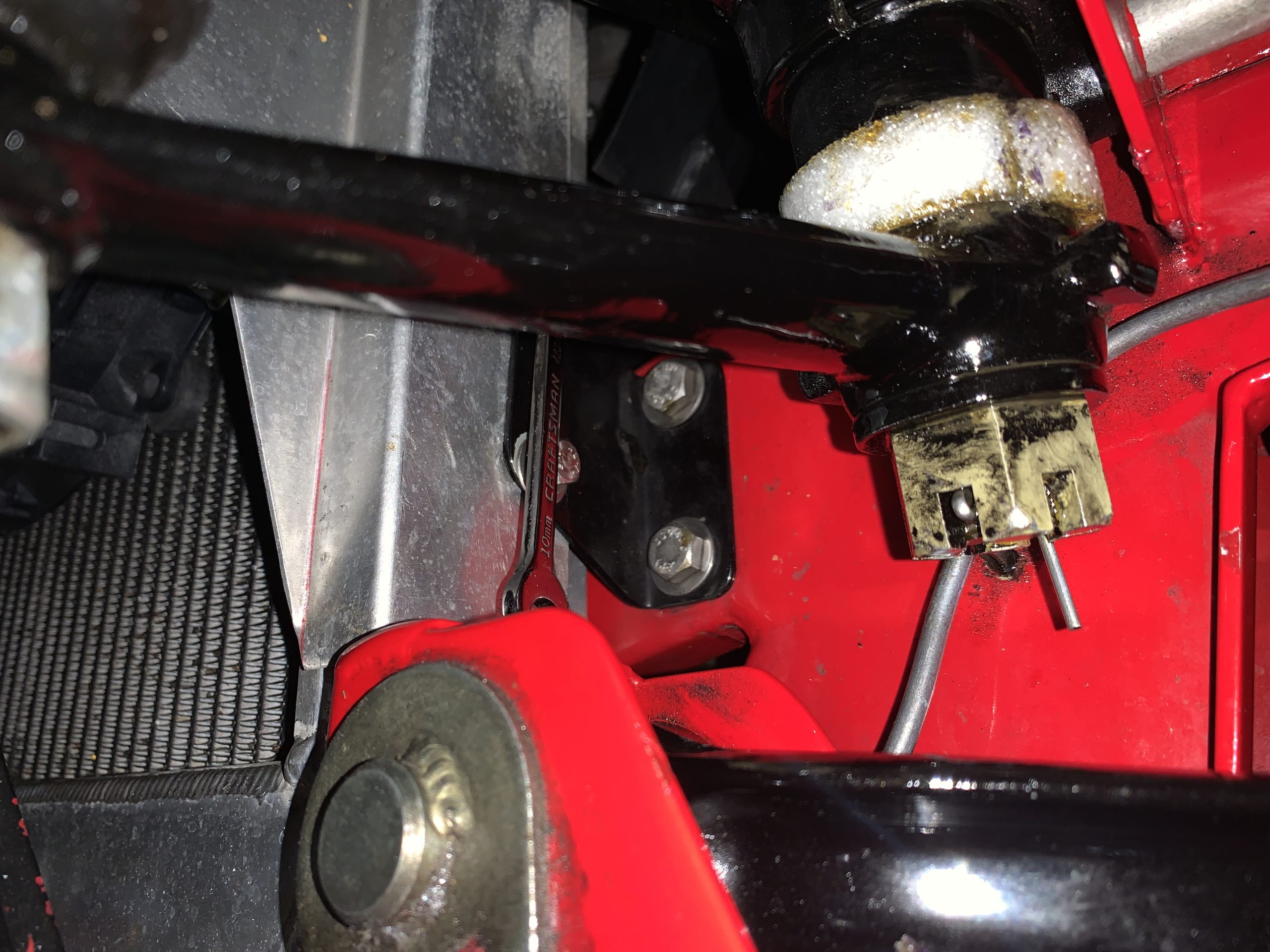
The radiator mounting bolts are metric. 6mm requiring a 10mm wrench. A zip tie is used to secure the coolant overflow tube to the radiator mount so that it cannot foul against the alternator fan.
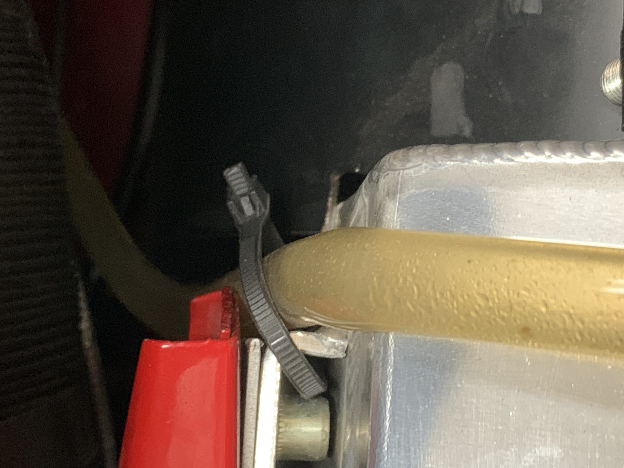
coolant overflow hose
I then removed the four lower radiator mounting bolts all with 10mm wrench.
Lower Radiator Mounting Bolts
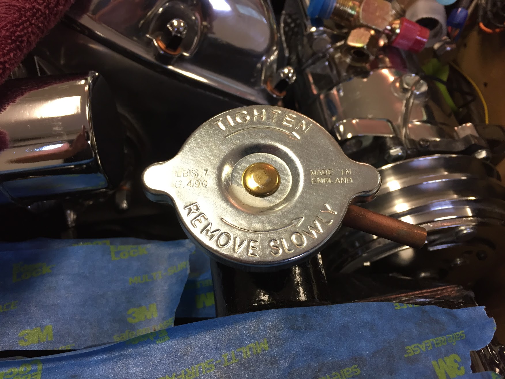
Disconnected the overflow hose from the radiator cap.
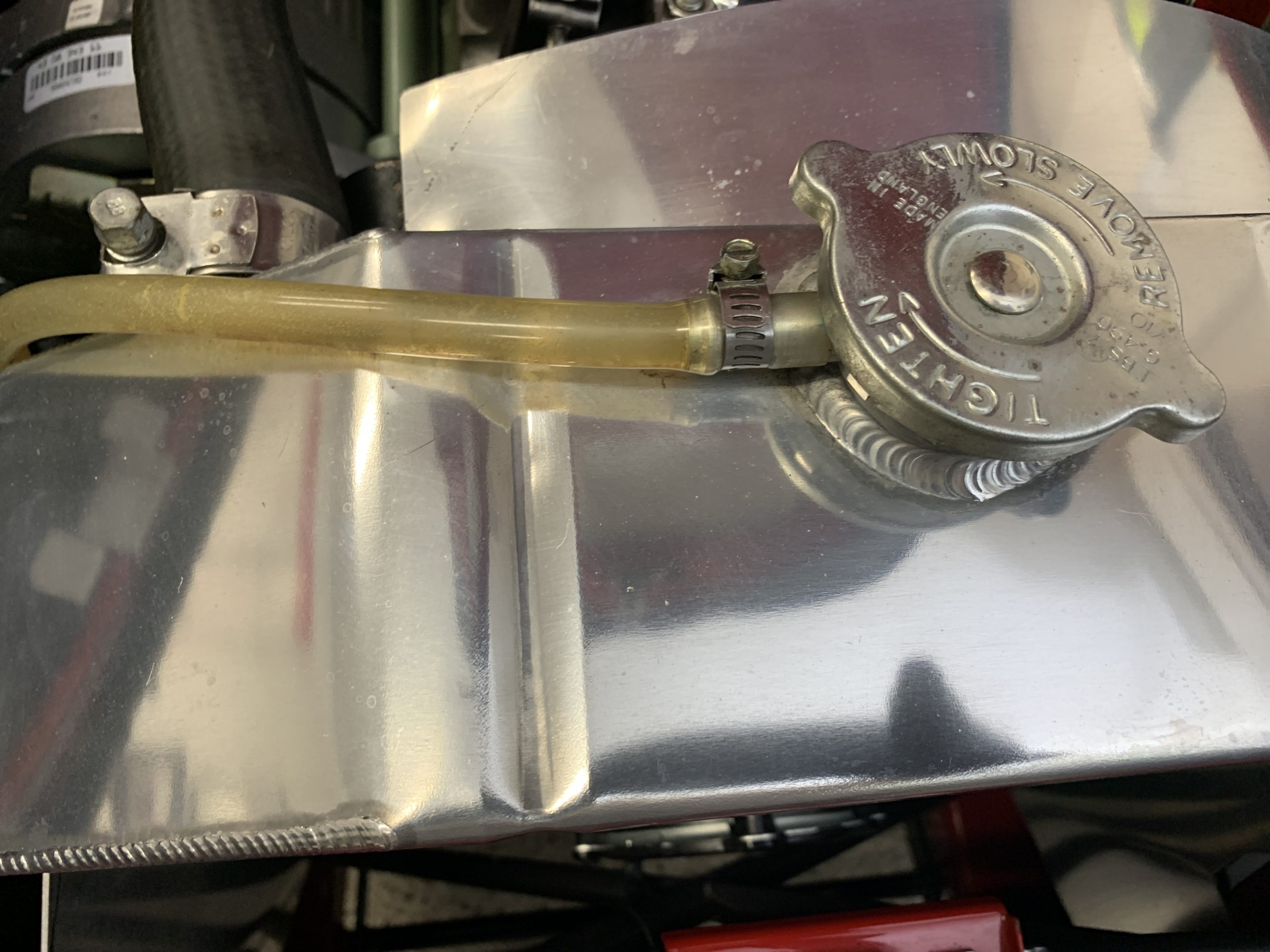
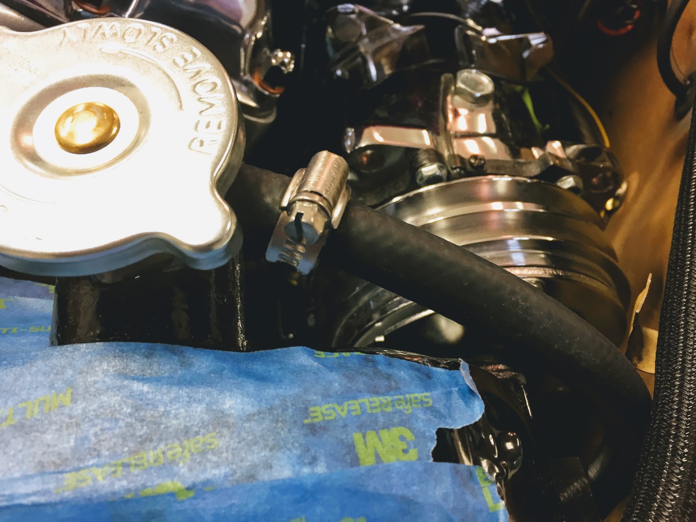
Radiator Overflow Tube Clamp at Radiator neck
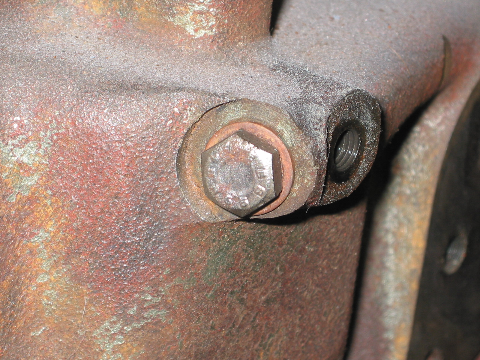
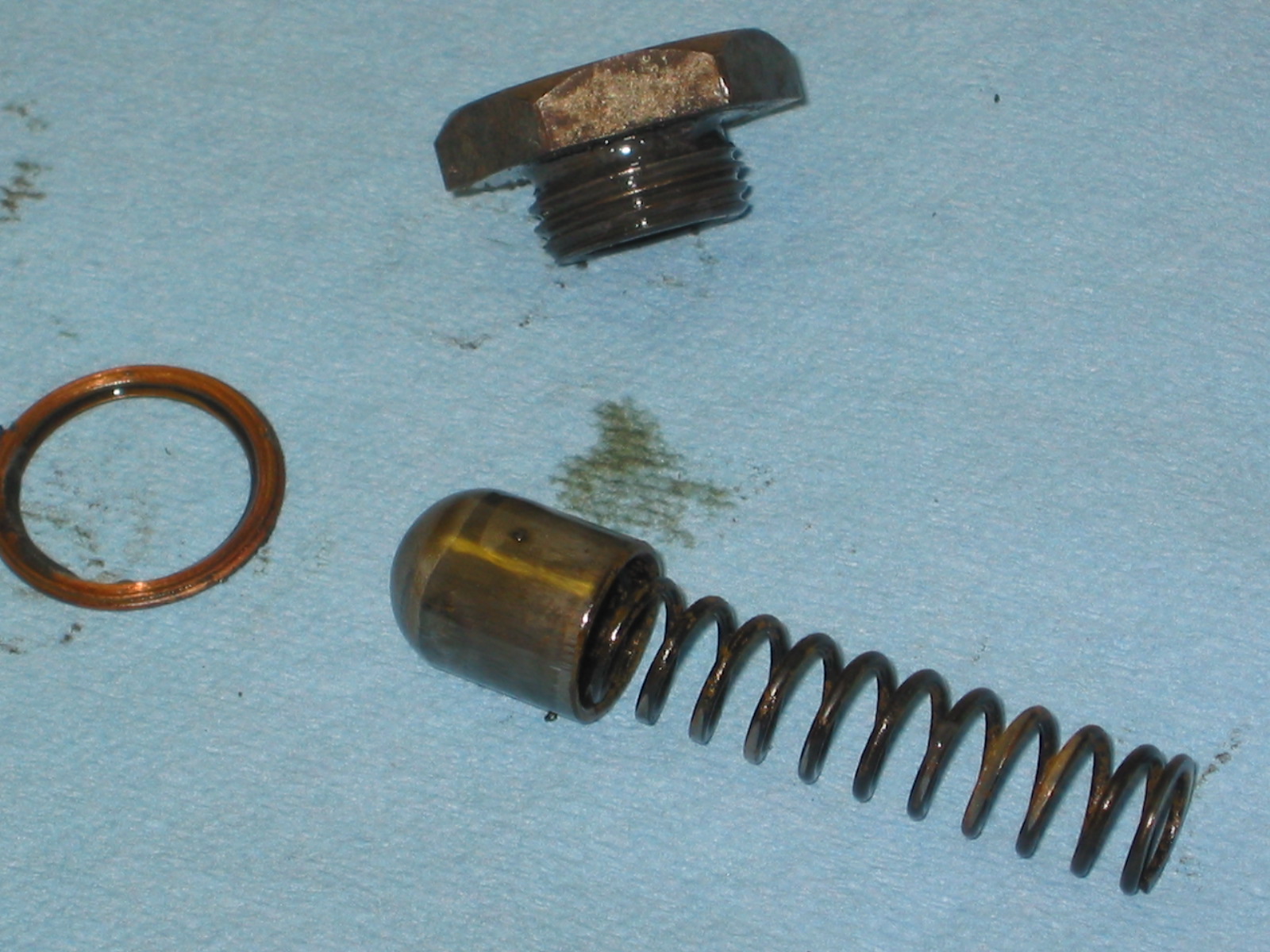
Removed the radiator drain plug with a 6mm hex Allen wrench and drained the coolant from the radiator. With the mounting bolts removed and the coolant drained one can push the bottom of the radiator forward providing easier access to the lower radiator hose clip. I then loosened the clip with a 10mm socket wrench and freed the hose, of course, more fluid drained out.
Radiator Drain Plug 6mm hex
I then loosened the upper radiator hose bracket at the radiator, again with a 10mm socket. To remove the hose I had to loosen the upper mount for the radiator shroud. It is a 10-32 hex head machine screw.
Radiator Hose Clamp for Upper Hose 10mm
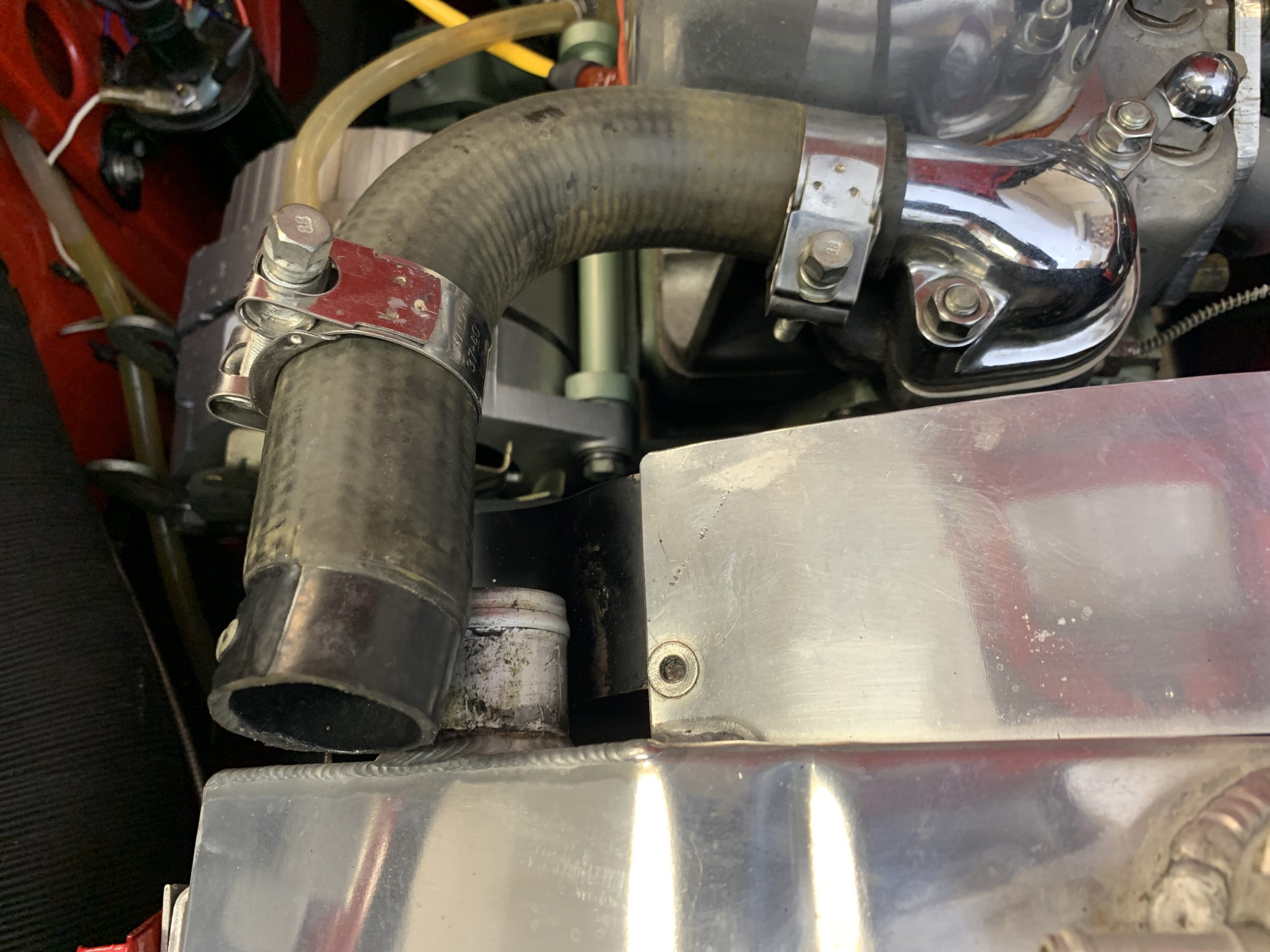
I Loosen the hose clamp at the thermostat housing and tilted the hose upward where I will leave it until I replace it with a new hose.
Upper Radiator Hose
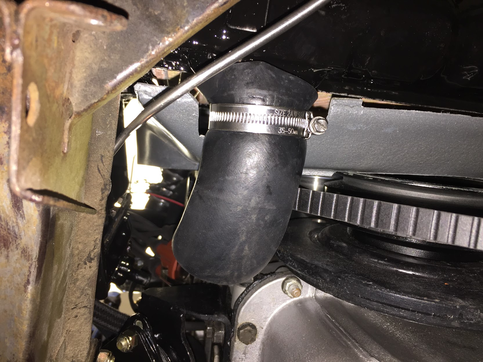
Then I moved on to loosening the clamp on the lower radiator hose for the heater pipe. This clamp requires a 7mm socket. I then loosened the clamp for the lower radiator hose at the water pump with a 8mm socket.
Lower radiator Hose Clamps
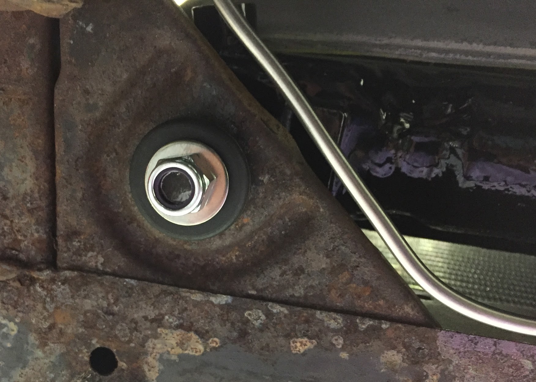
The next step is to remove the lower shroud mounts on both sides of the radiator which is connected to the lower radiator mount. This requires a half inch socket with a long extension for the right side.
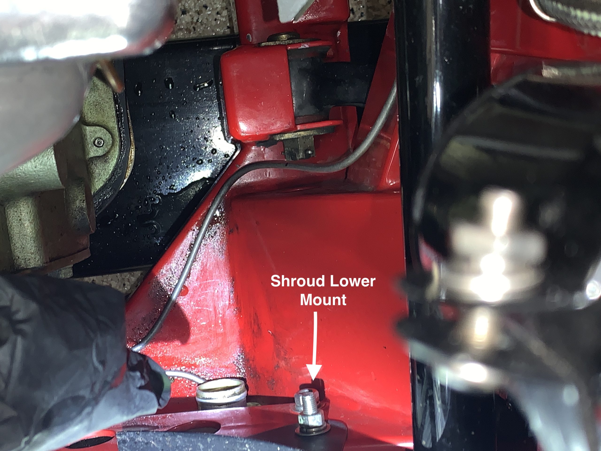
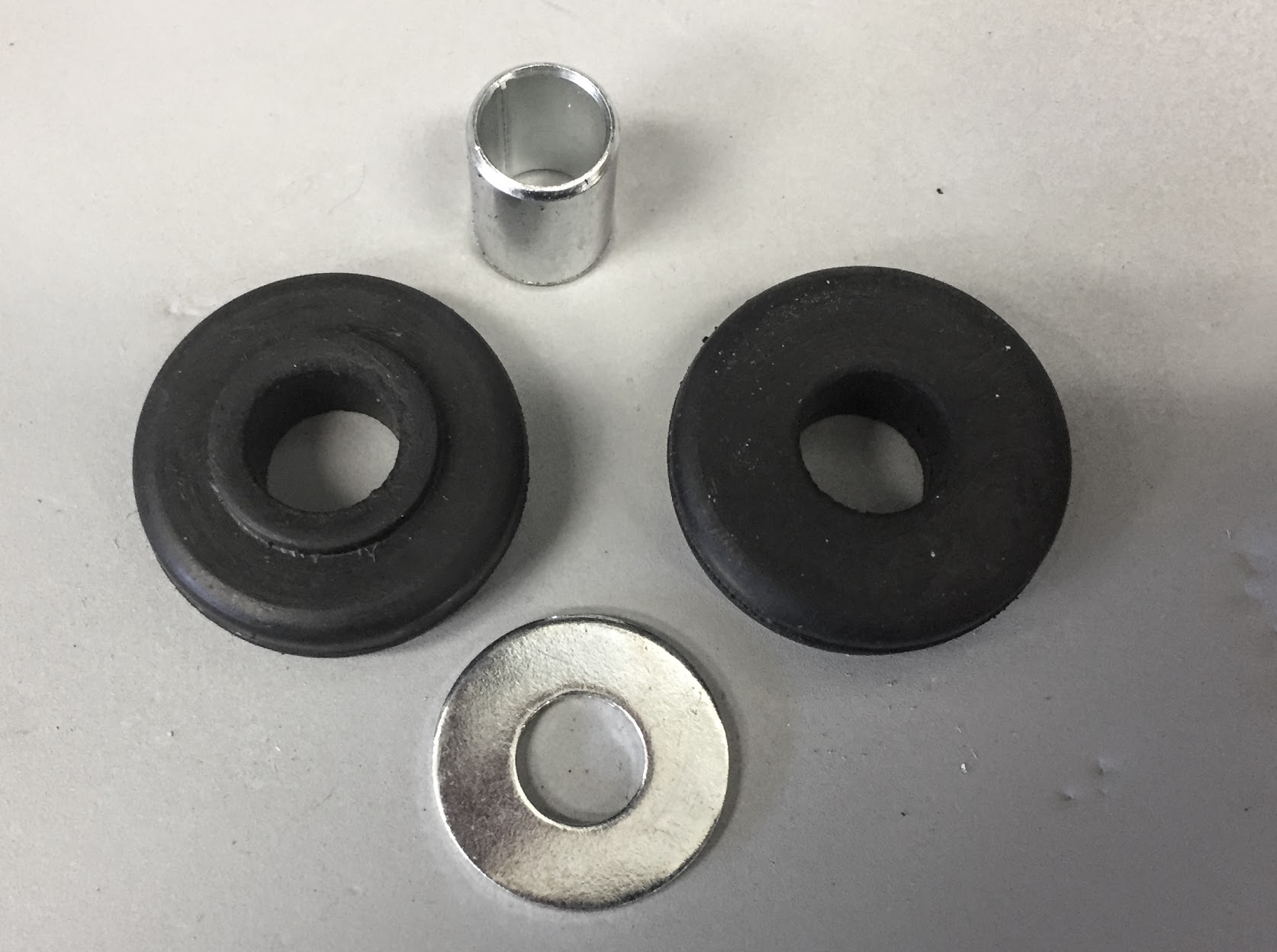
Radiator Shroud Lower Mounts
I then disconnected the wiring to the electric radiator fan. This requires unplugging the electrical connector and disconnecting the clamp securing the wire.
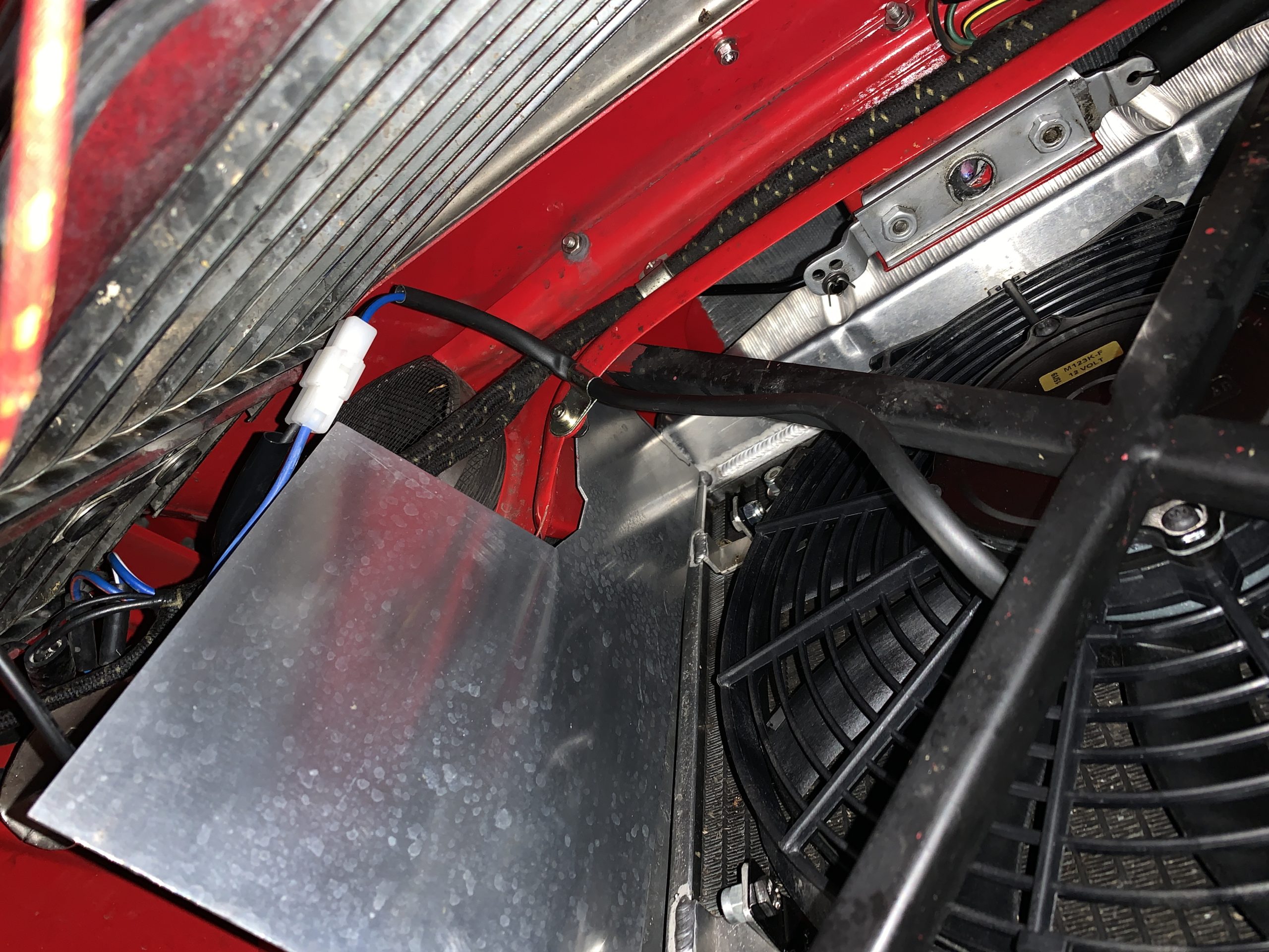
Electric fan Wiring Connector
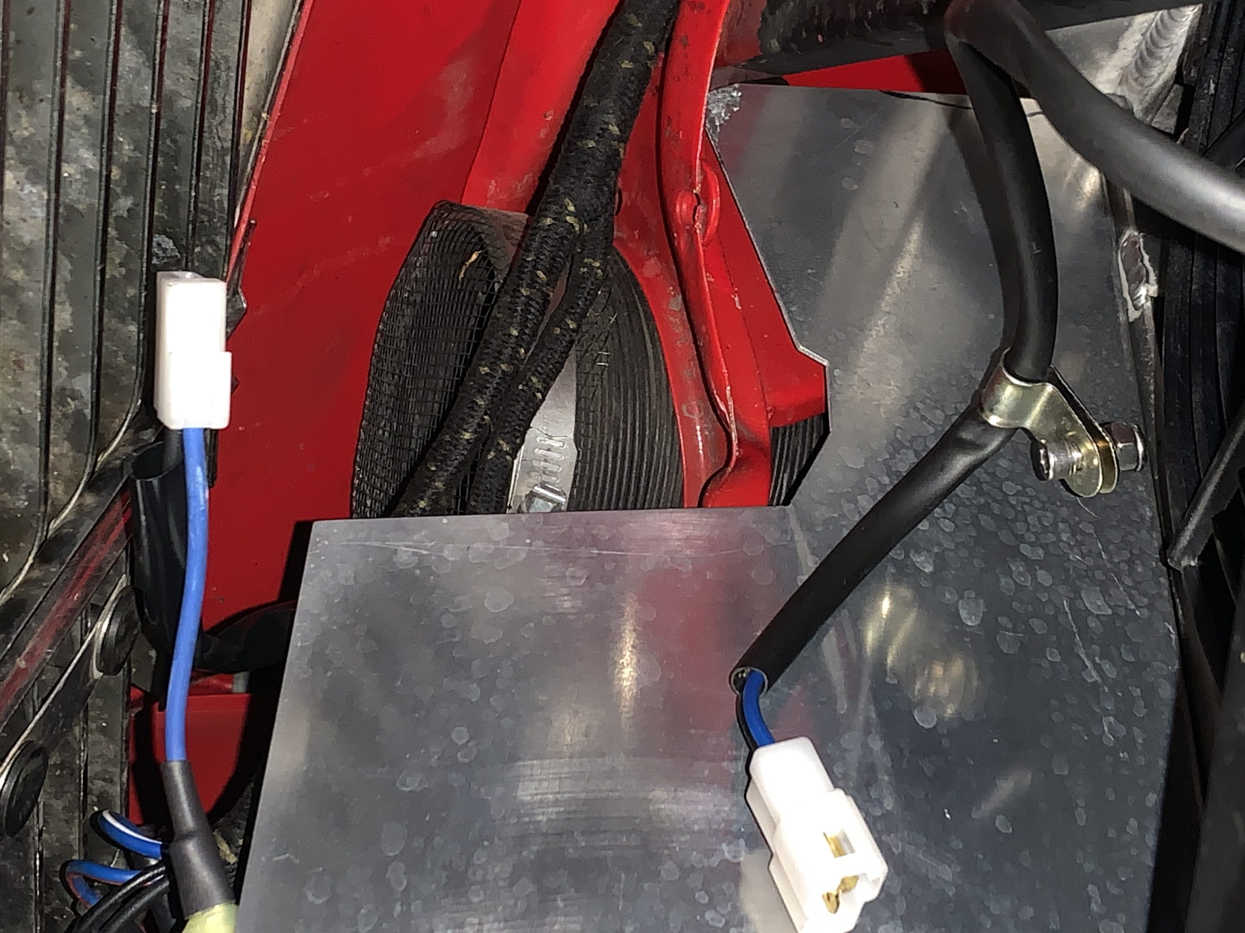
Electric Fan wiring and clip disconnected
I was then able to lift the radiator out from the car as well as the left and right baffles.

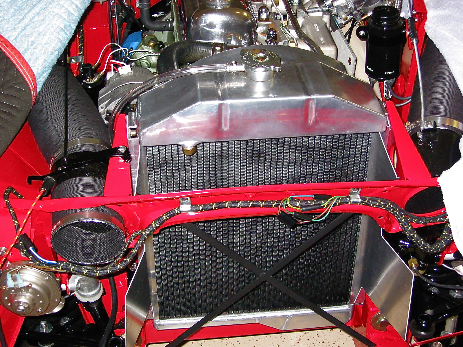
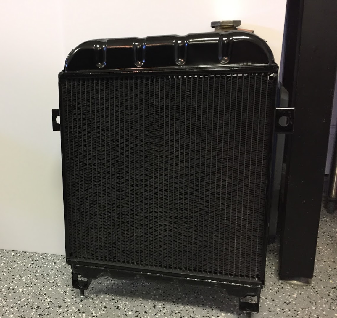
Radiator and Fan Assembly Removed From Car
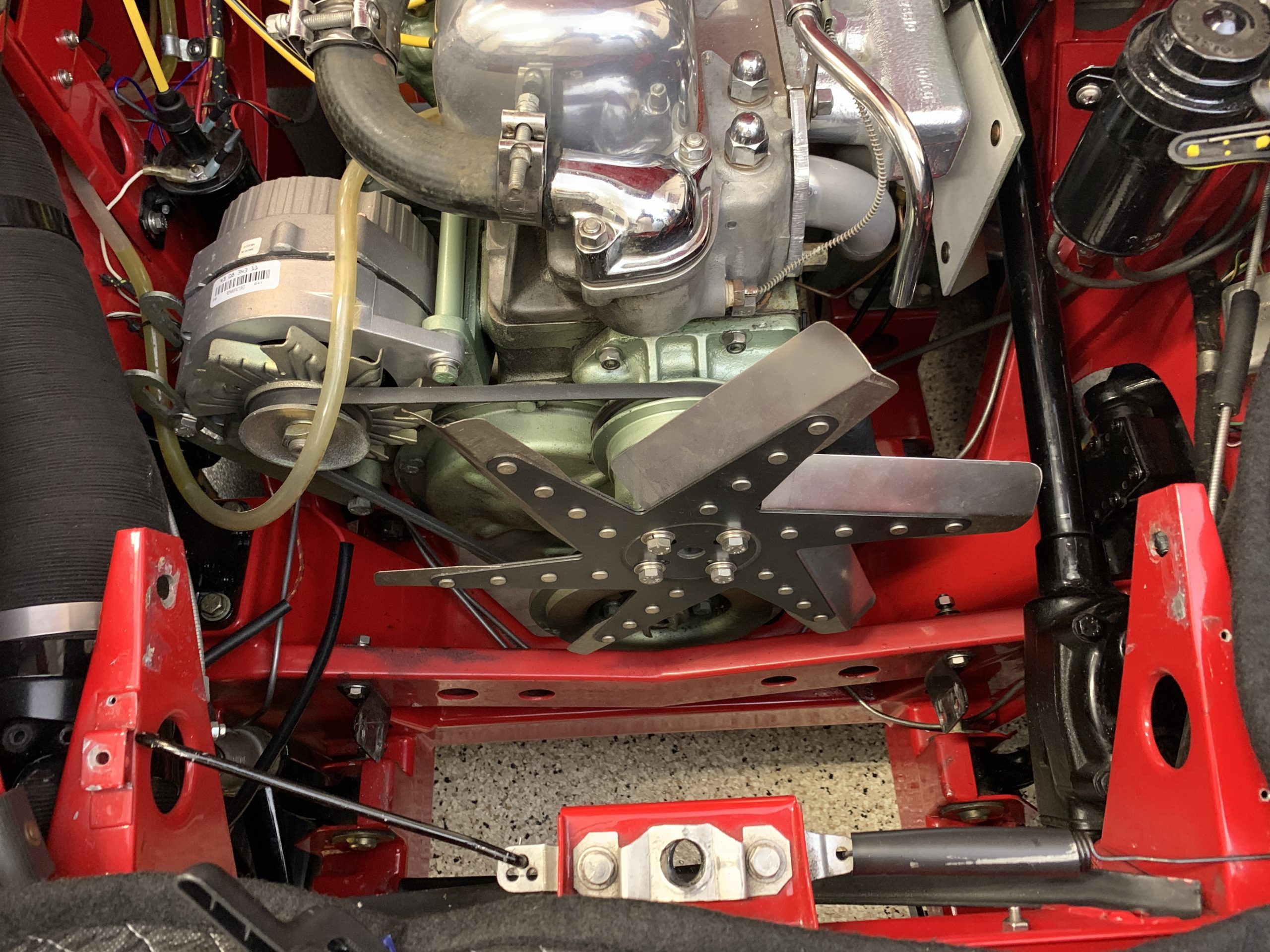
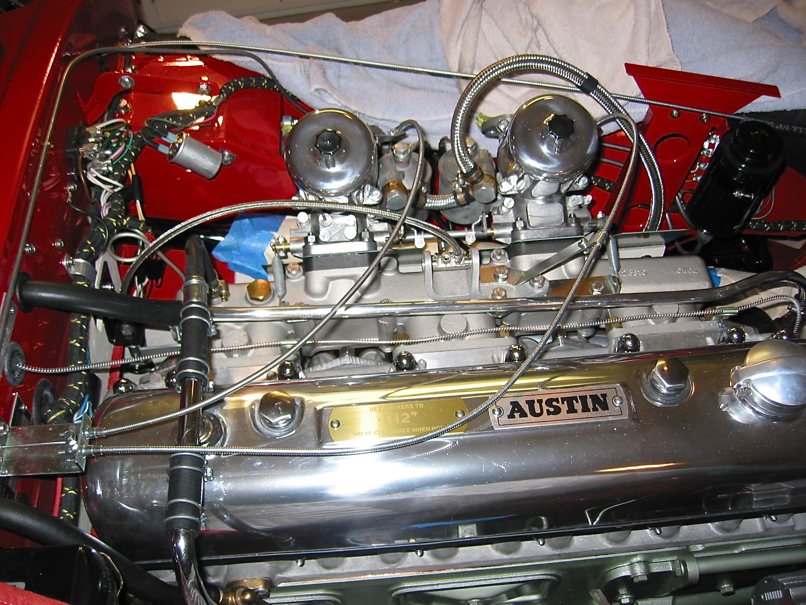
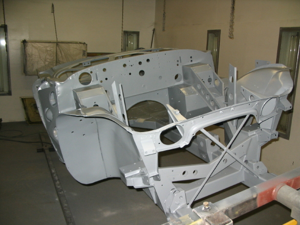
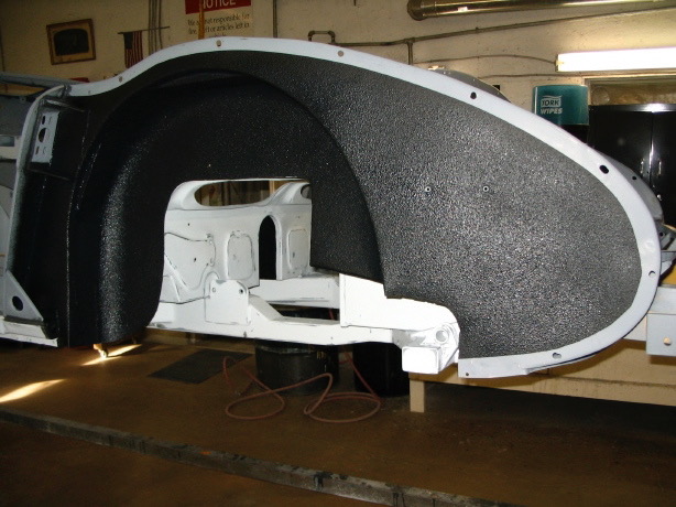
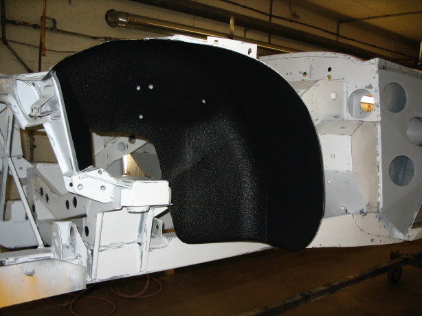
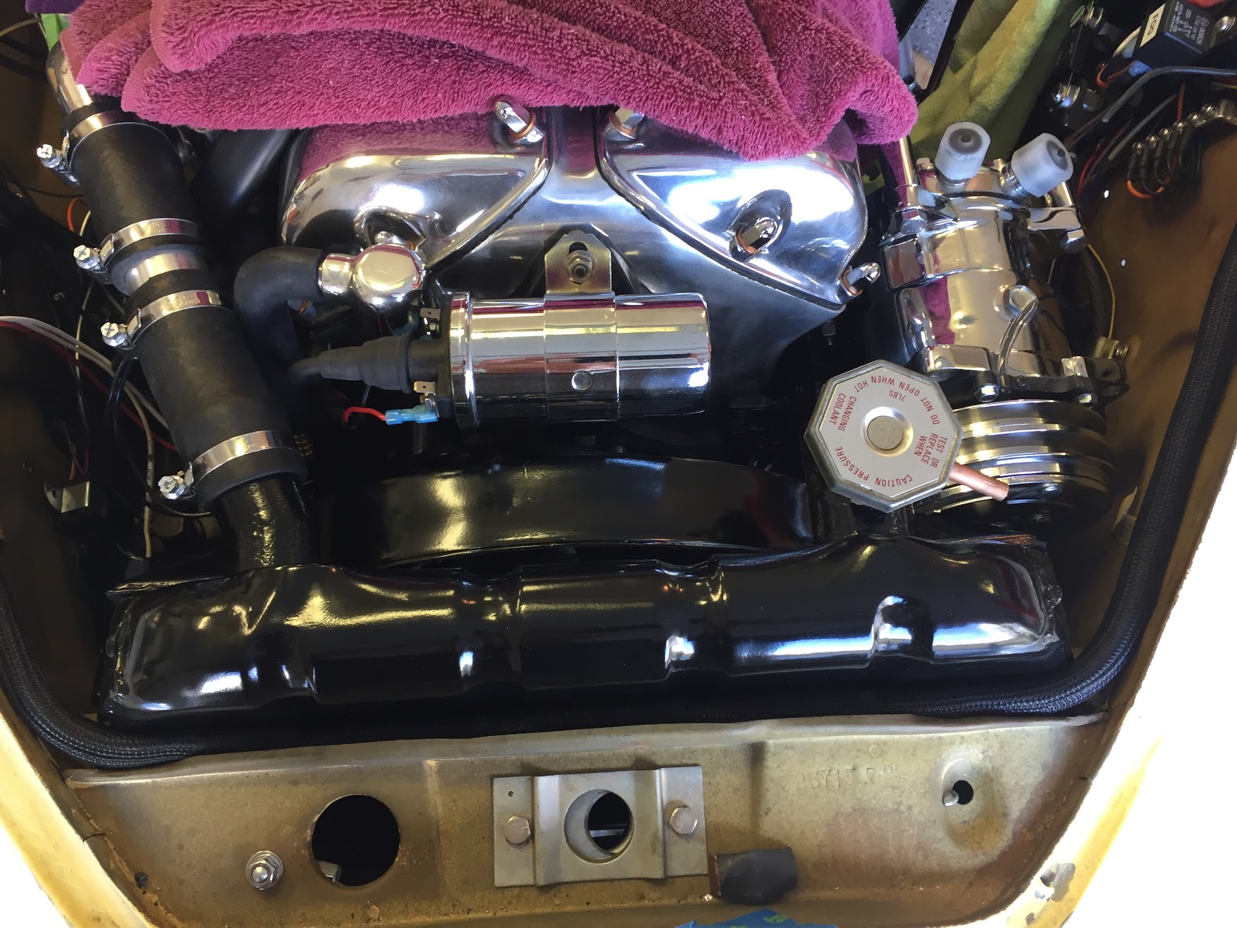
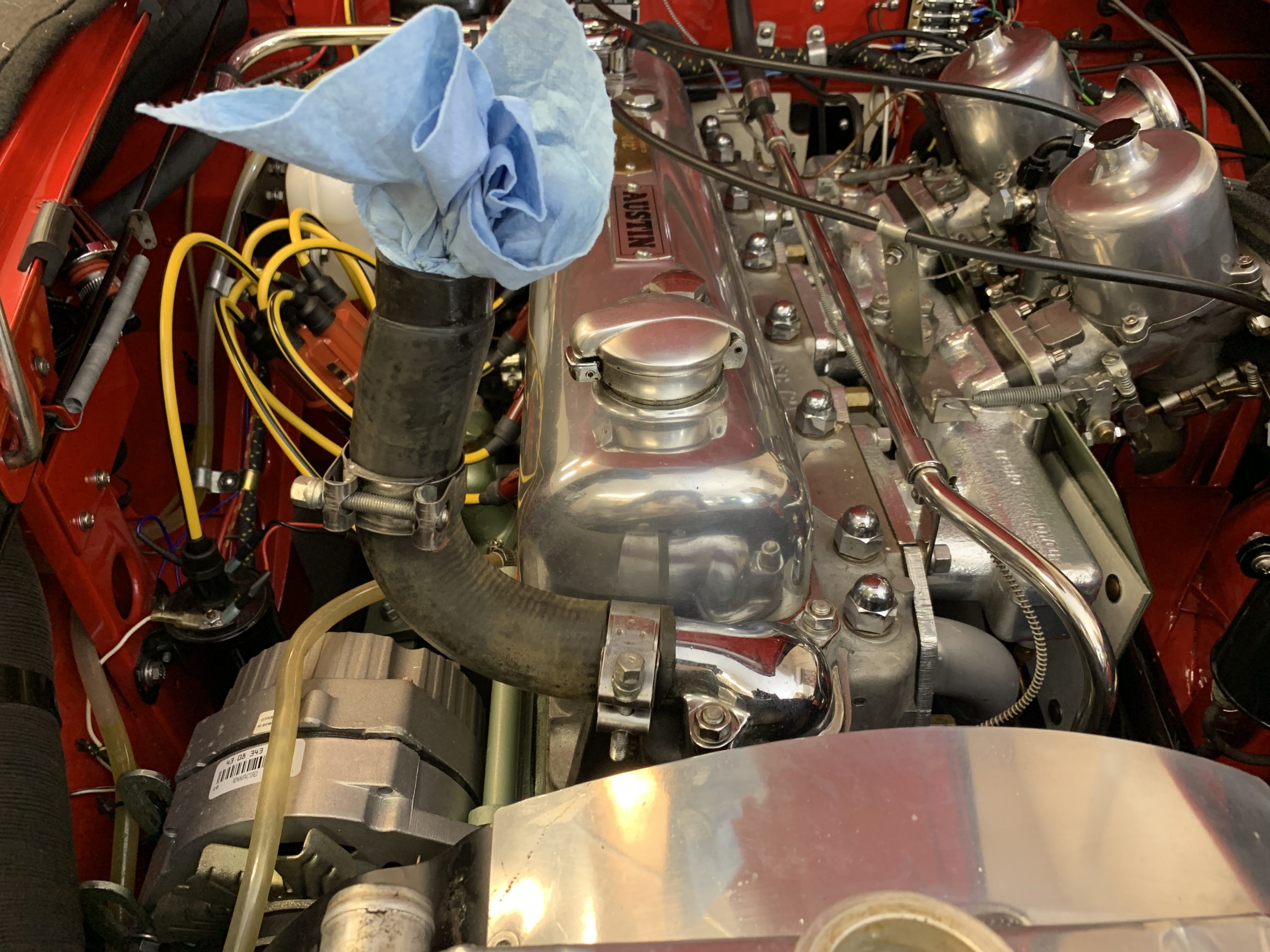
Engine Bay Sans Radiator and Baffling
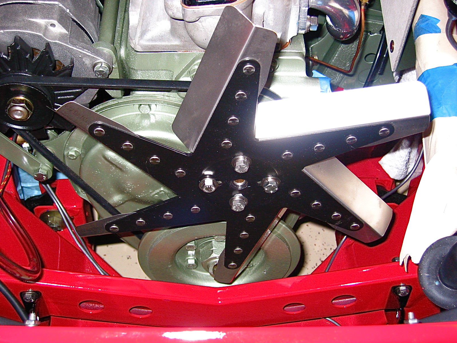
The next step is to remove the engine fan and its spacer. Four bolts with 1/2” wrench.

Engine Fan Mounting
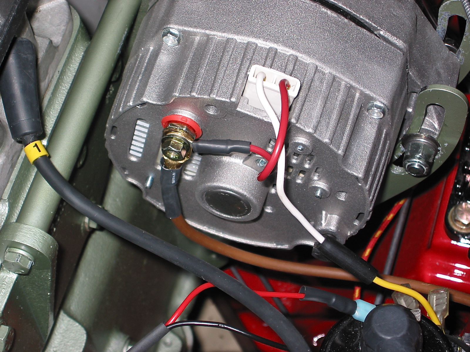
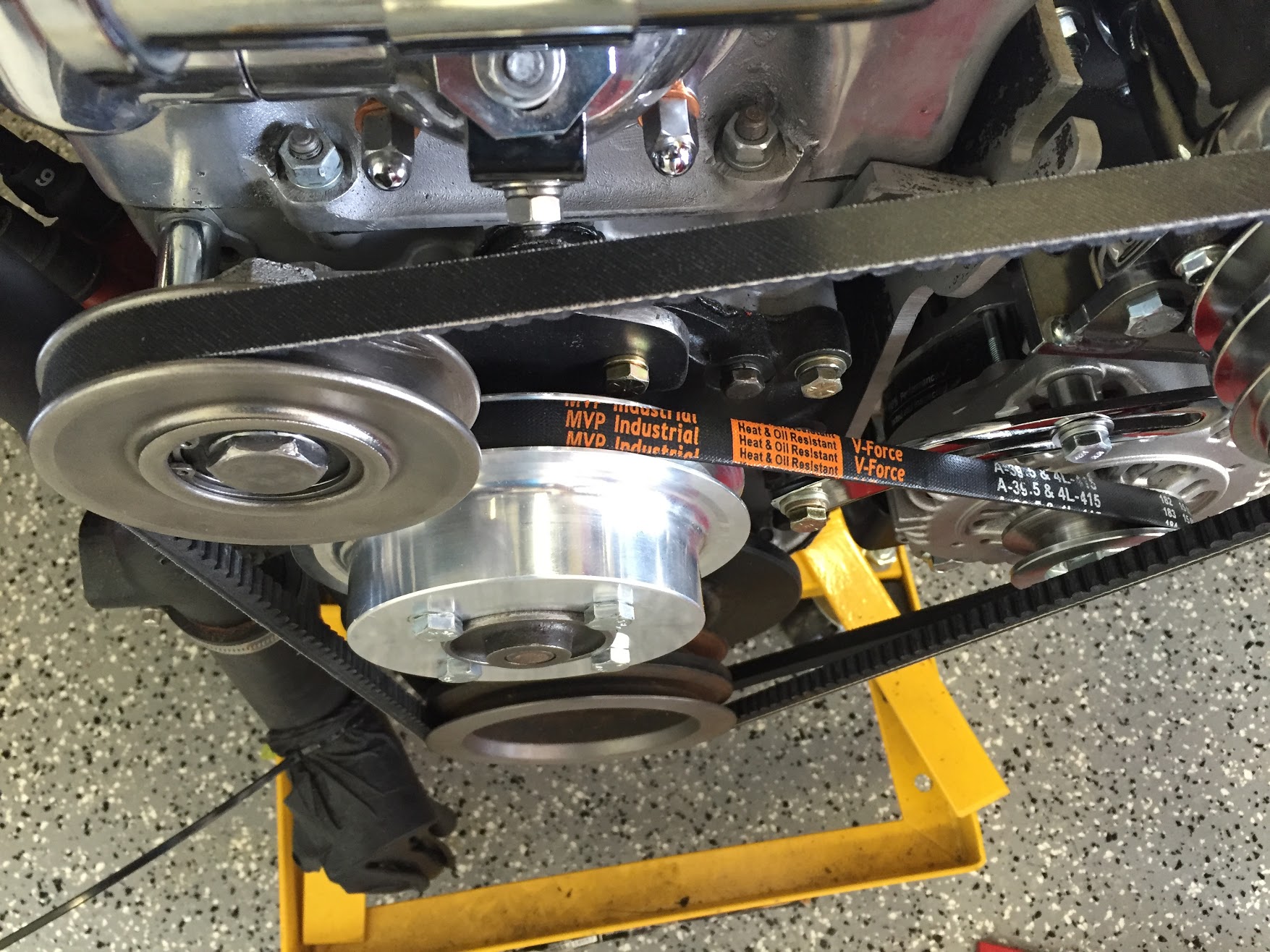
I then needed to take tension off of the fan belt by loosening the alternator swing bracket and locking nut. The locking nut is 13mm while the others are 9/16”.
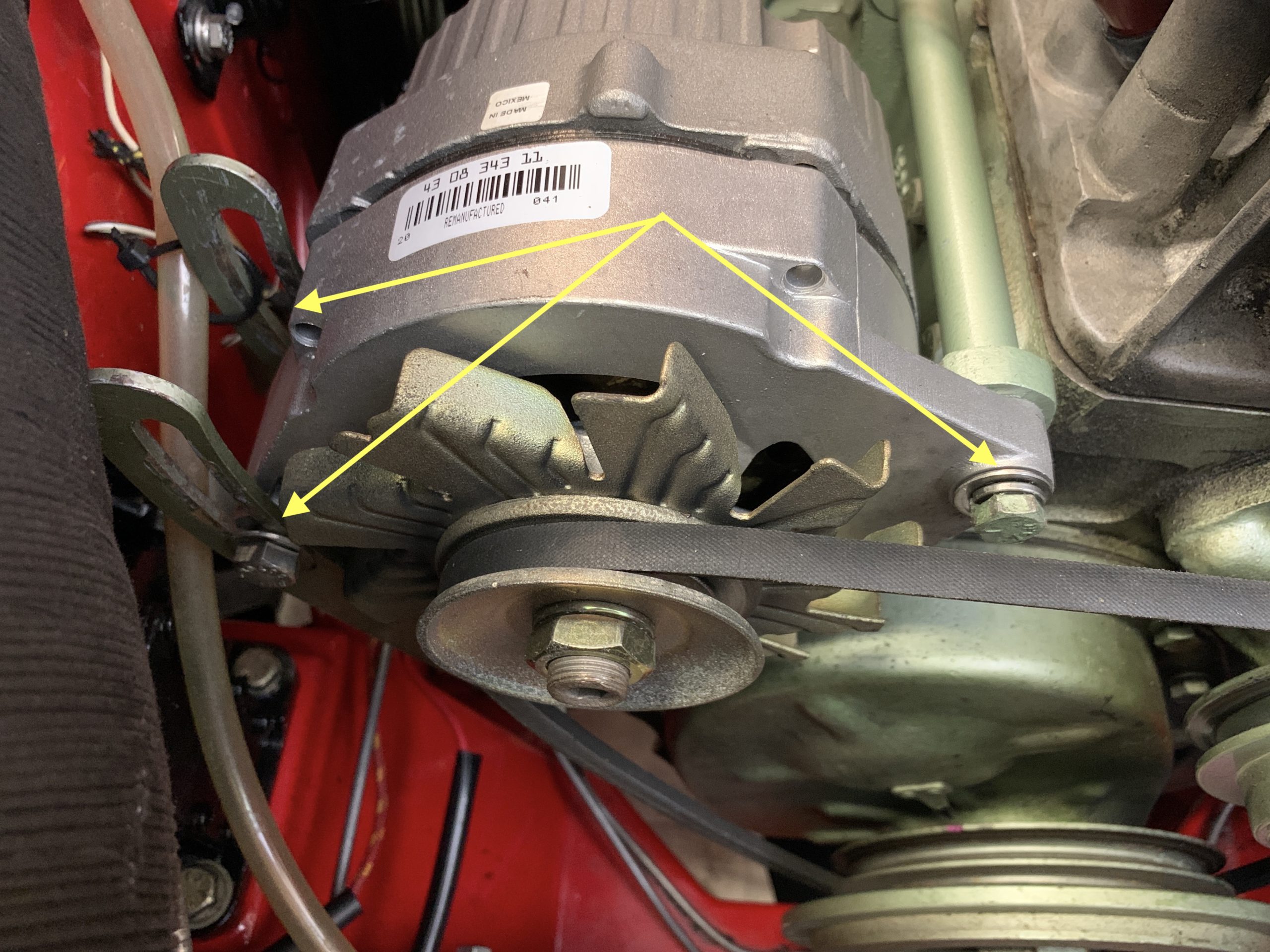
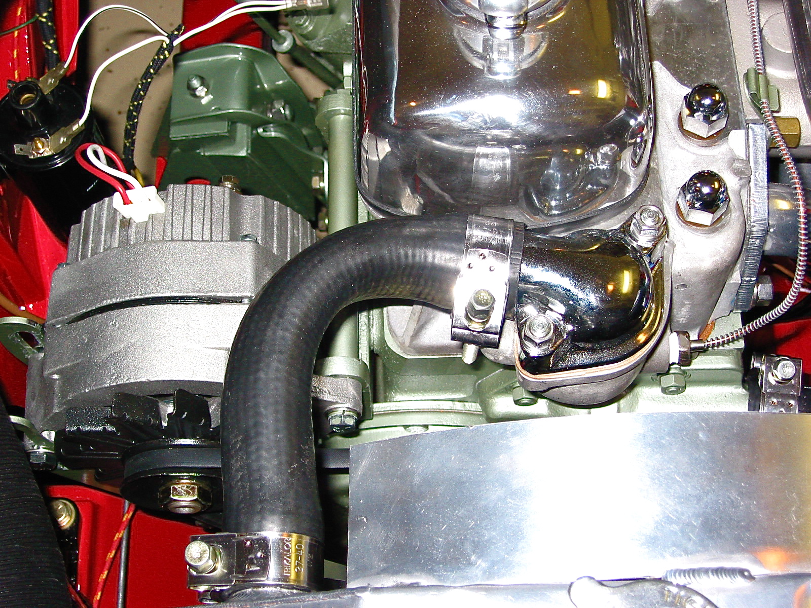
Alternator loosening points
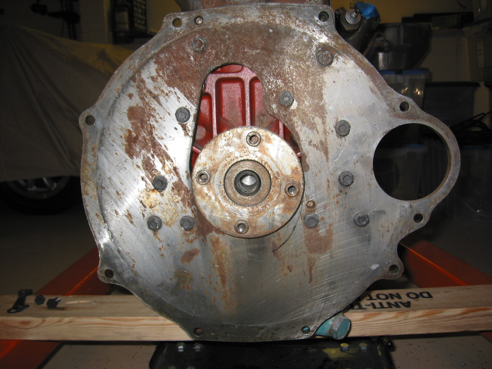
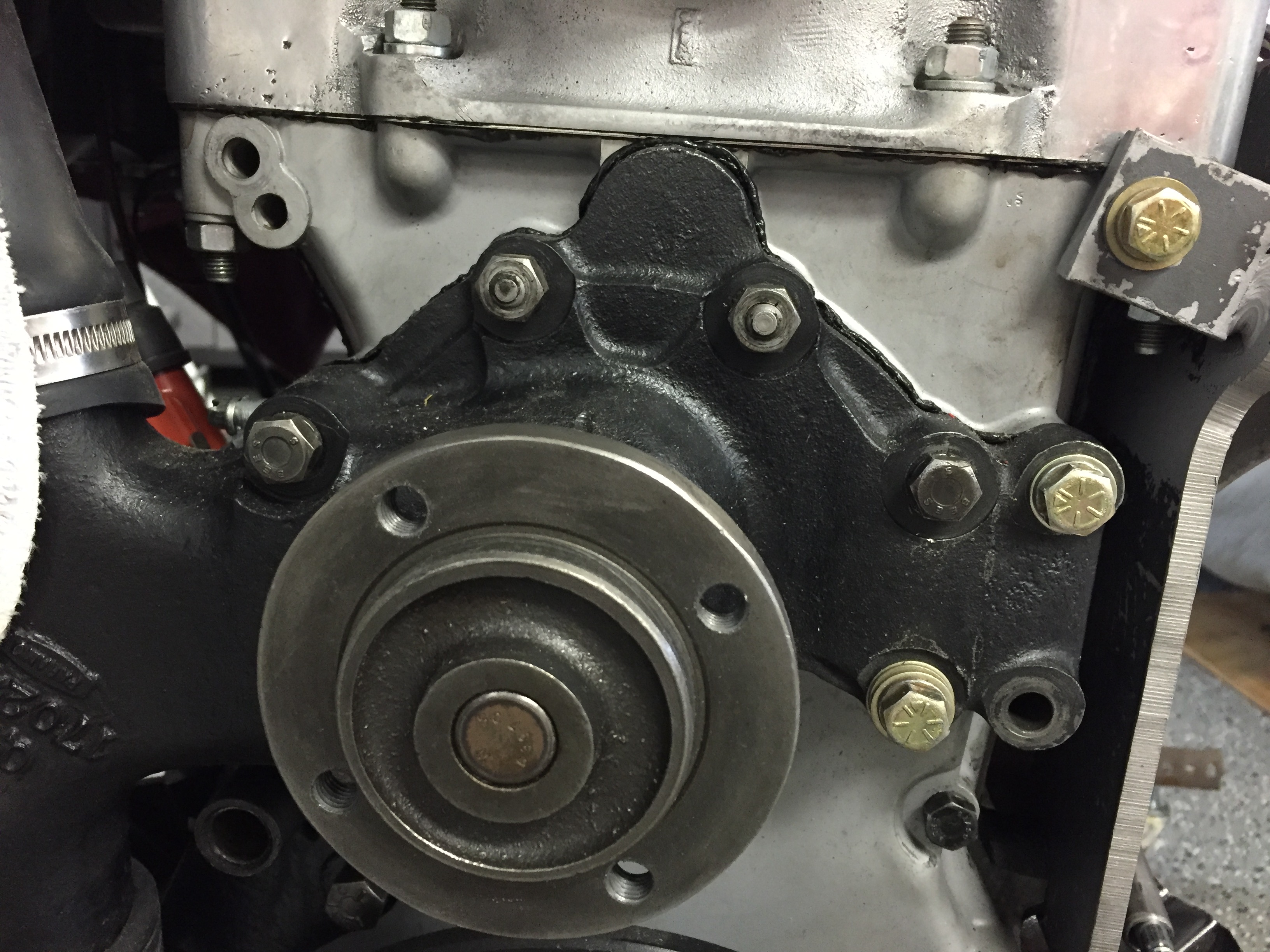
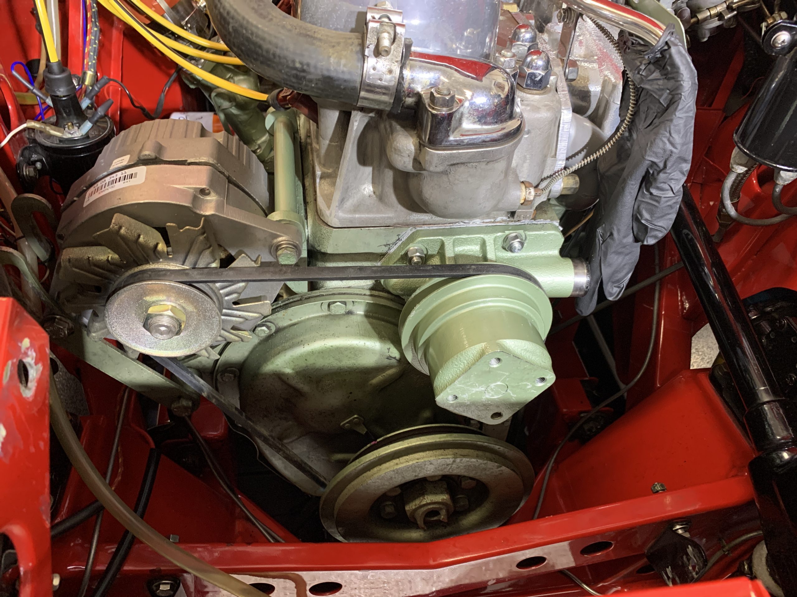
Following removal of the old fan belt, I removed the nuts and split washers on the four water pump studs, gave the pump body a few taps and removed the pump. Again, be prepared for coolant spillage. The lower center nut is a bit hard to access, but it is doable. I then used a blade and some brake cleaner and cleaned up the surface of the block to prepare for the pump gasket.
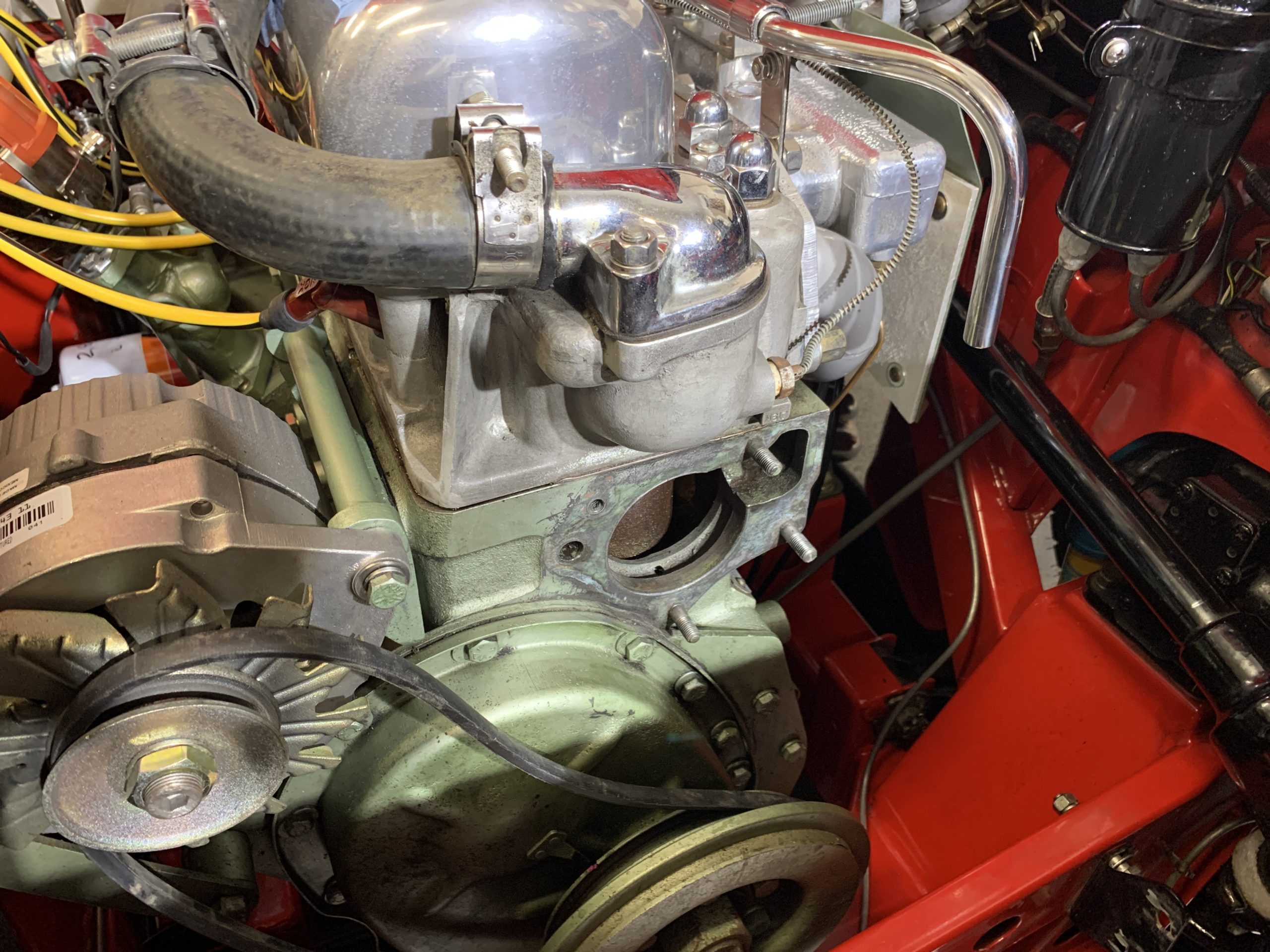
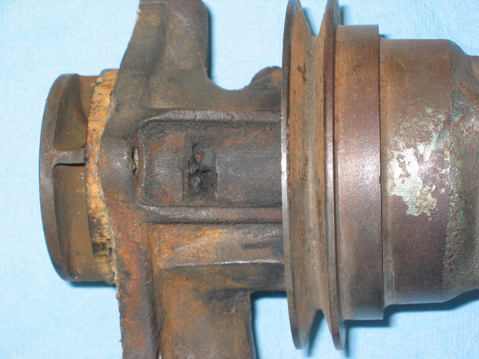
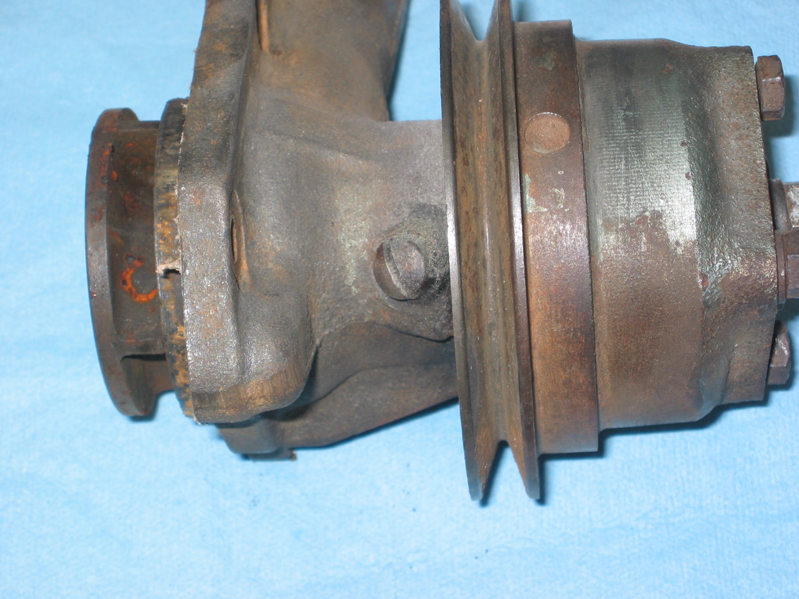
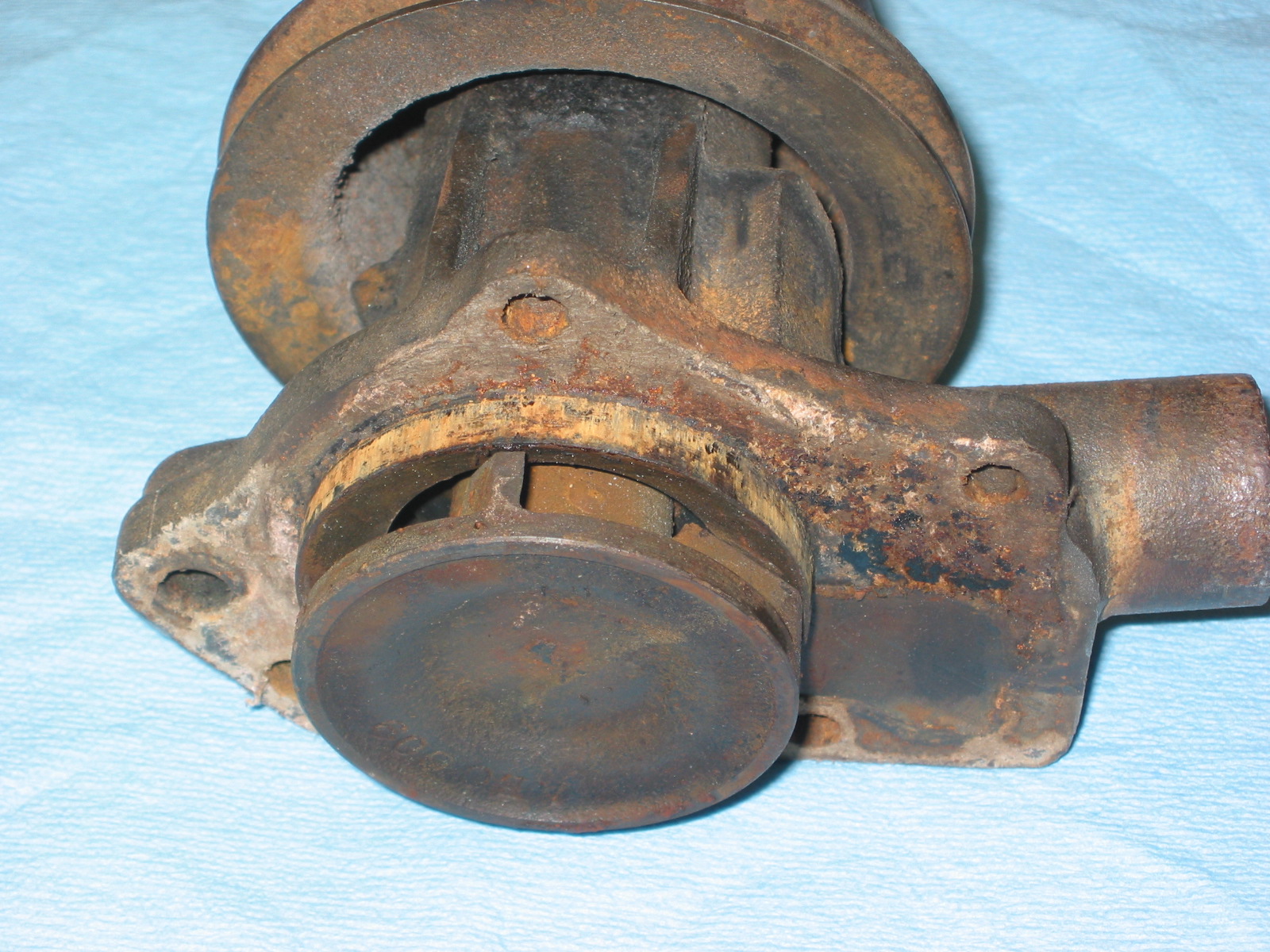
Water pump removed
I removed the four water pump studs from the engine using my handy-dandy stud remover which worked beautifully.
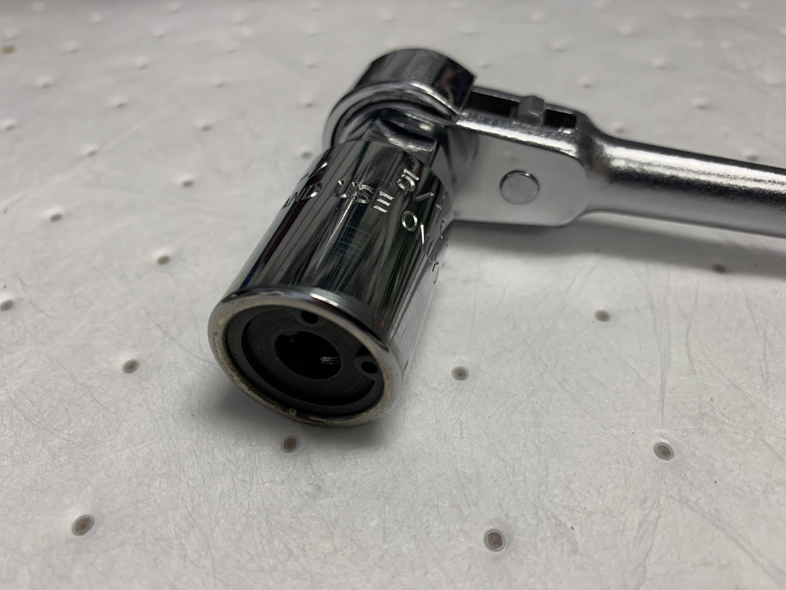
5/16″ Stud Removal Tool
I then chased the threads in the block just to be sure that they were nice and clean.
Cleaning water pump stud threads
Then using the two nut method I installed the new studs with a little blue Loctite on the engine end.
New studs installed with a little blue locktite on the threads of the engine side:

Water Pump Studs Installed
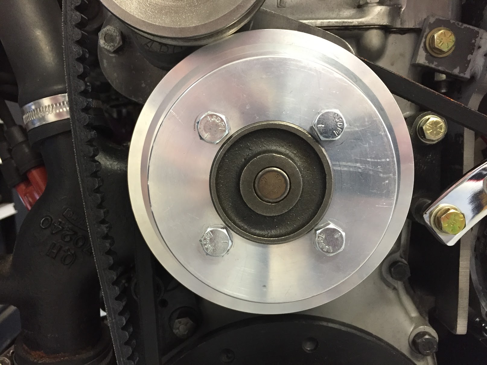
After installing the new water pump using Permatex Water Pump and Thermostat Housing RTV silicone sealant and the new gasket, I then installed a new Gates 43” fan belt and tightened the alternator in place.
Water Pump, Pulley and New fan Belt Installed
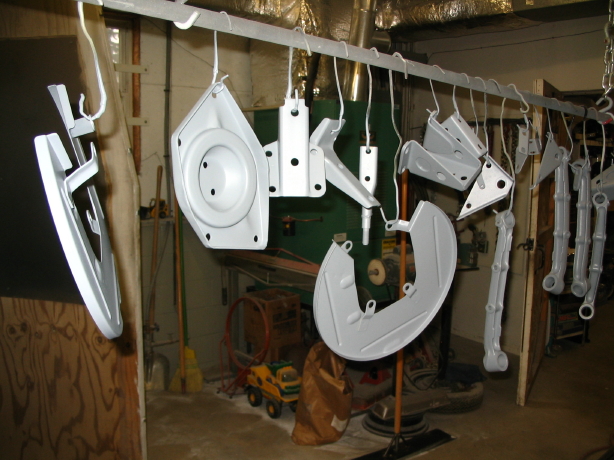
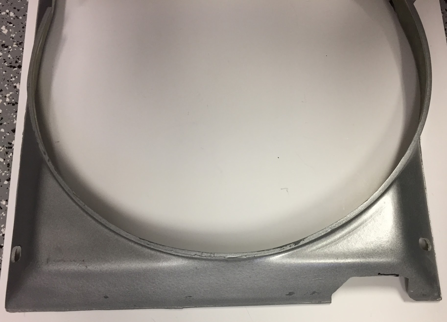
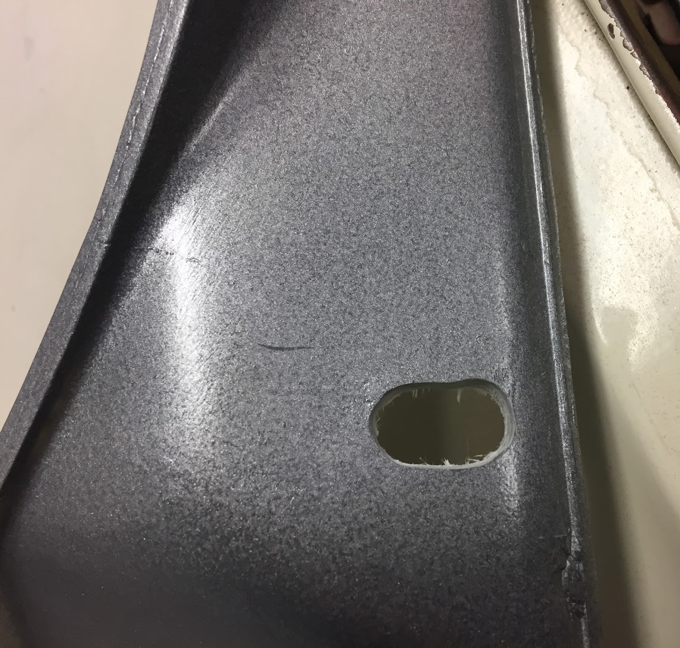
While they were out I freshened up the two pieces of the fan shroud just a little sanding and some fresh paint.
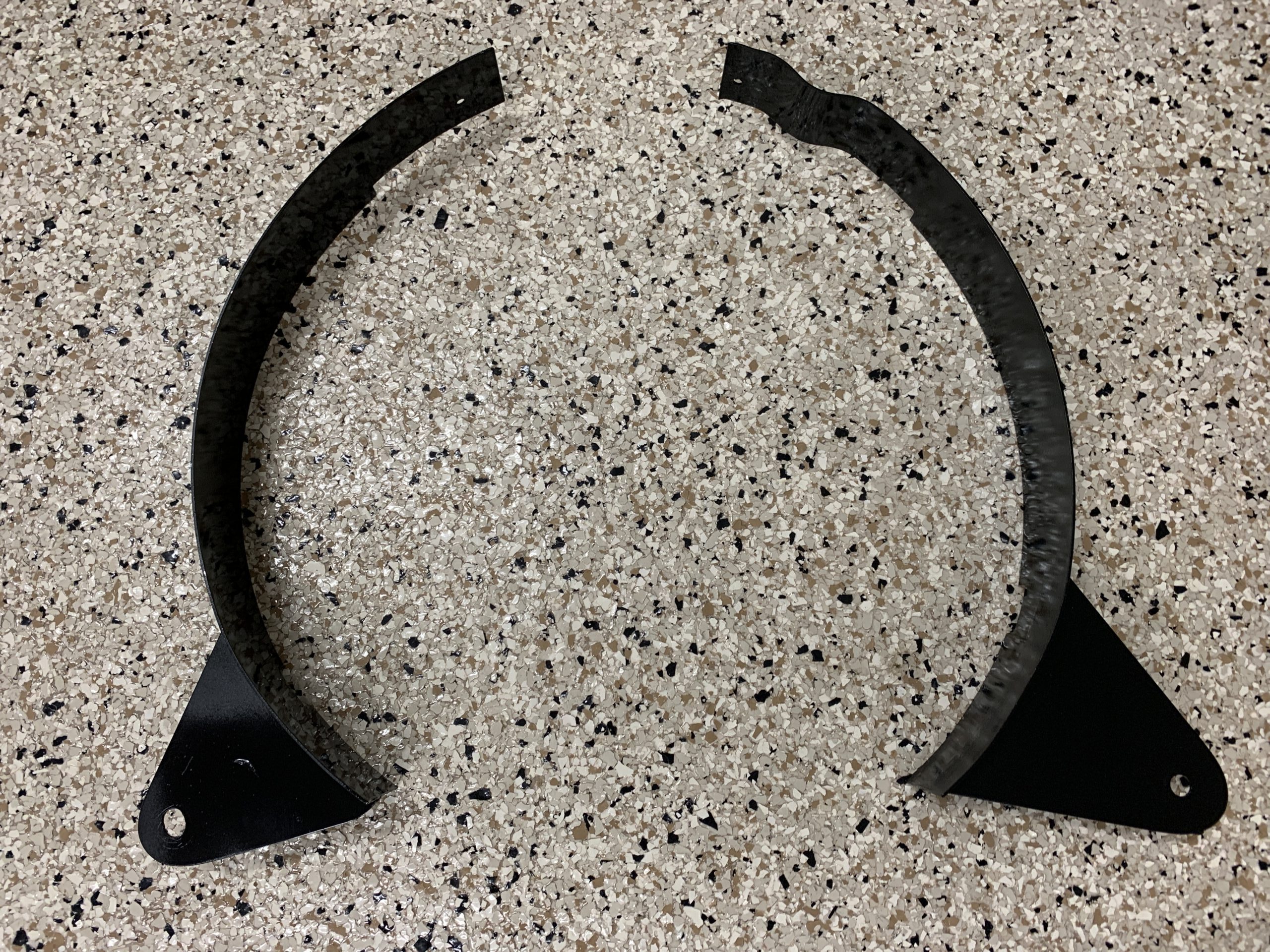
Fan Radiator Shroud Repainted
I then loosely installed the shroud to the frame of the car.
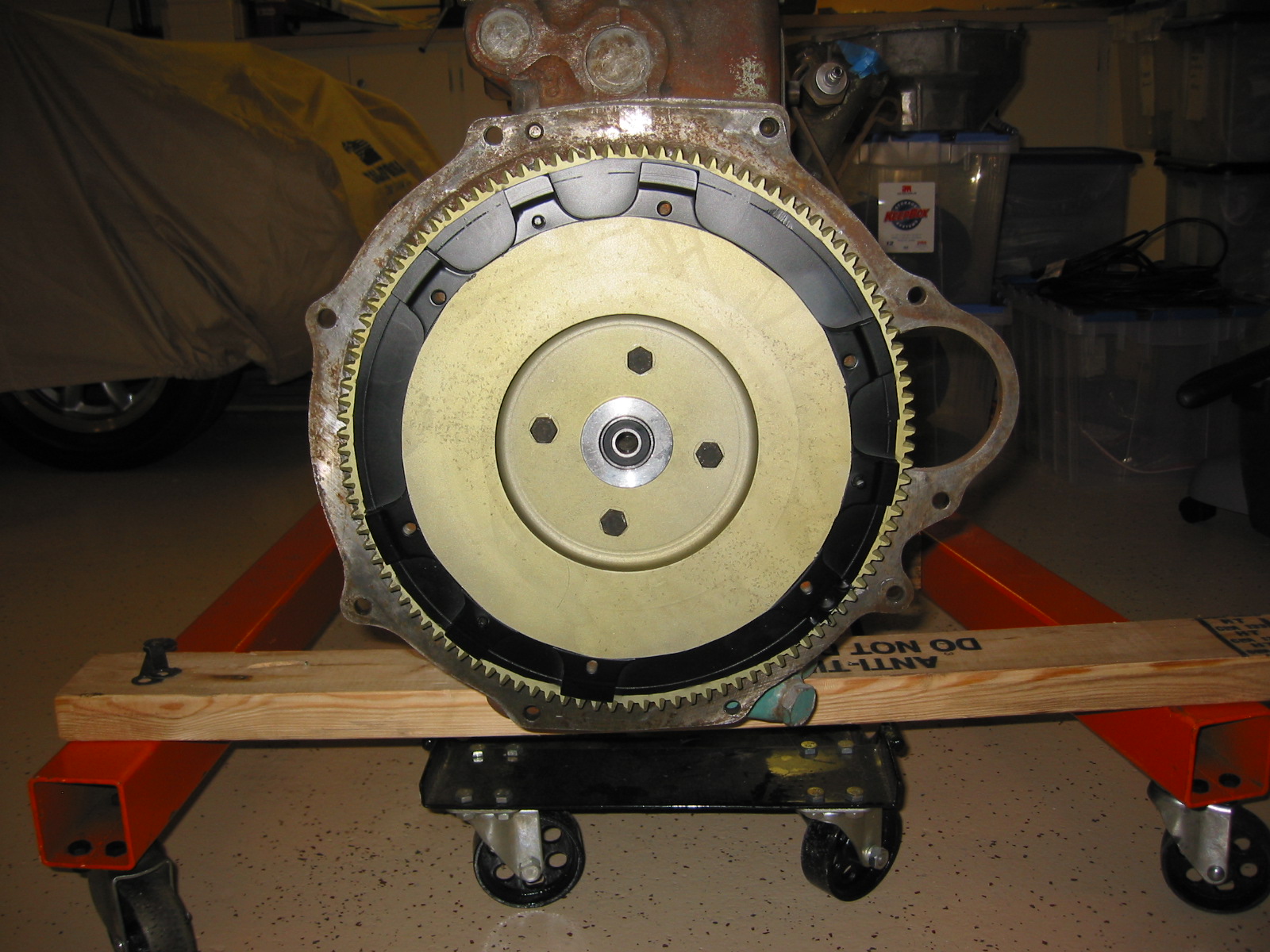
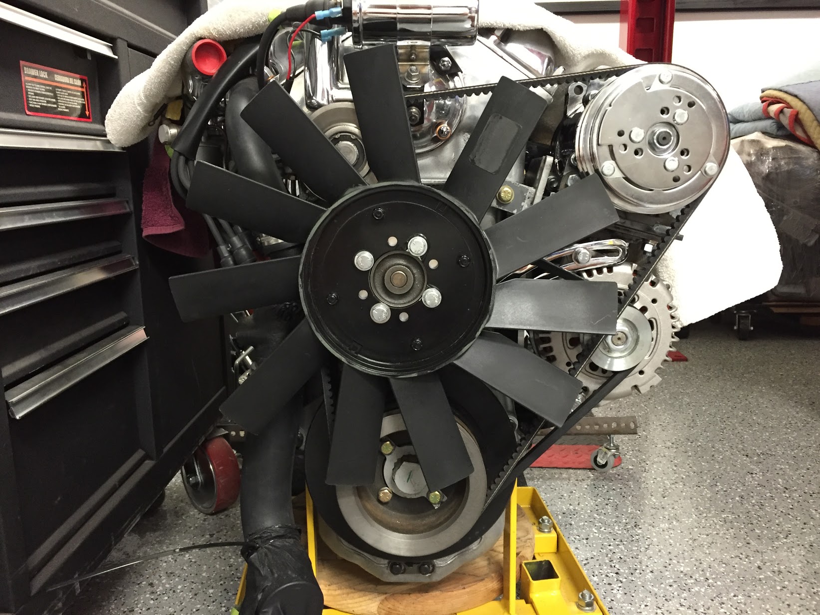
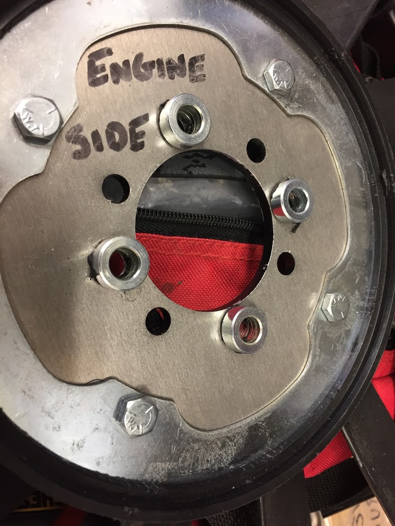
Next was the installation of the new fan from AH Spares with four 5/16-24 x 7/8” hex bolts.
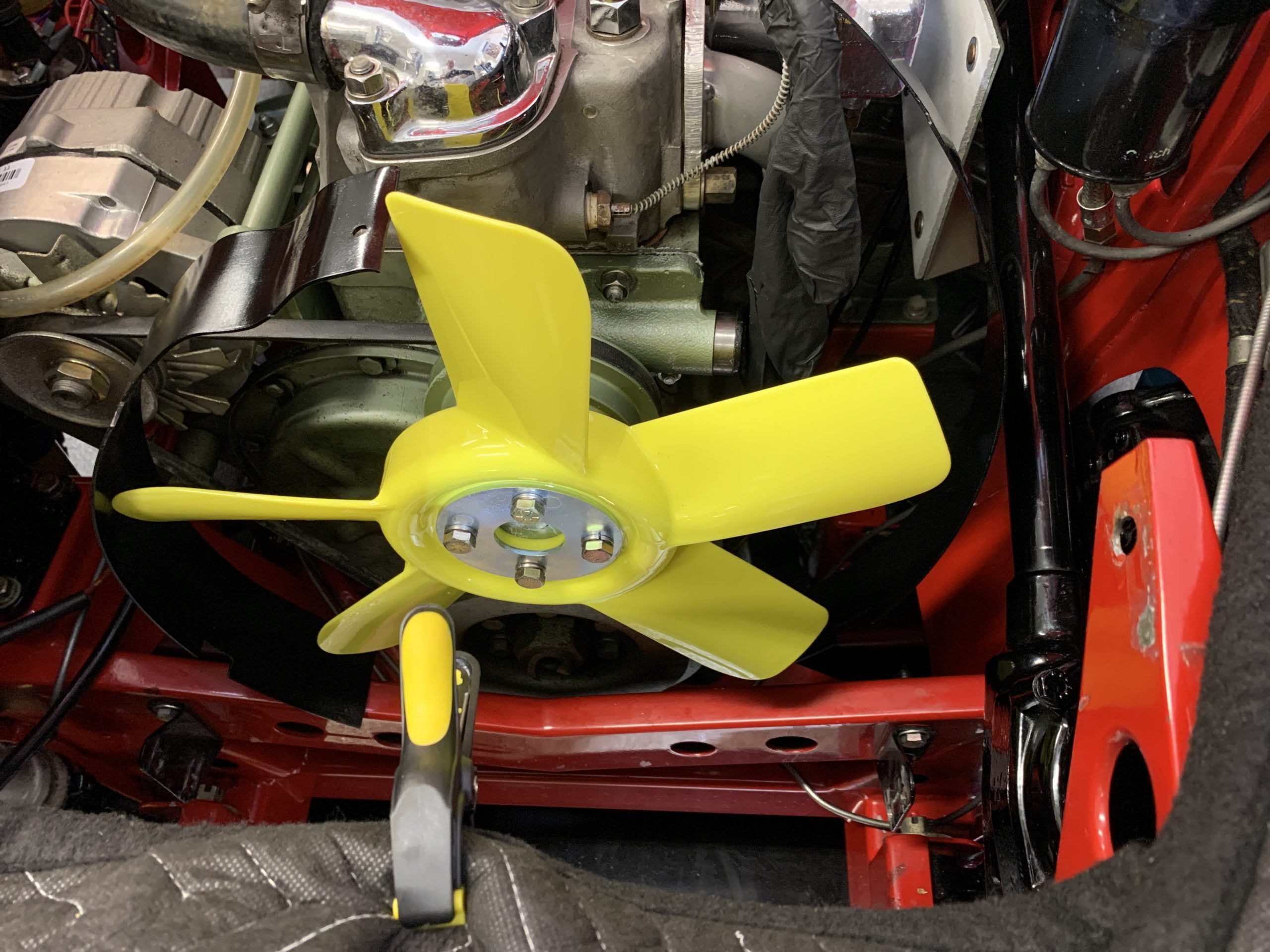
AH Spares Fan Installed
I then installed the new Kevlar radiator hoses. So they are ready to connect to the radiator once in.

New Hoses Installed
I lifted the radiator into position and loosely attached the upper two mounting bolts. I then raised the car on the lift to get to the lower mounting brackets.
I reinstalled the radiator drain plug, connected and clamped the lower radiator hose, and loosely fitted the four screws into the lower brackets.
Then the biggest challenge was to install the two air baffles around the radiator. I installed both from below. Difficult but got them in.
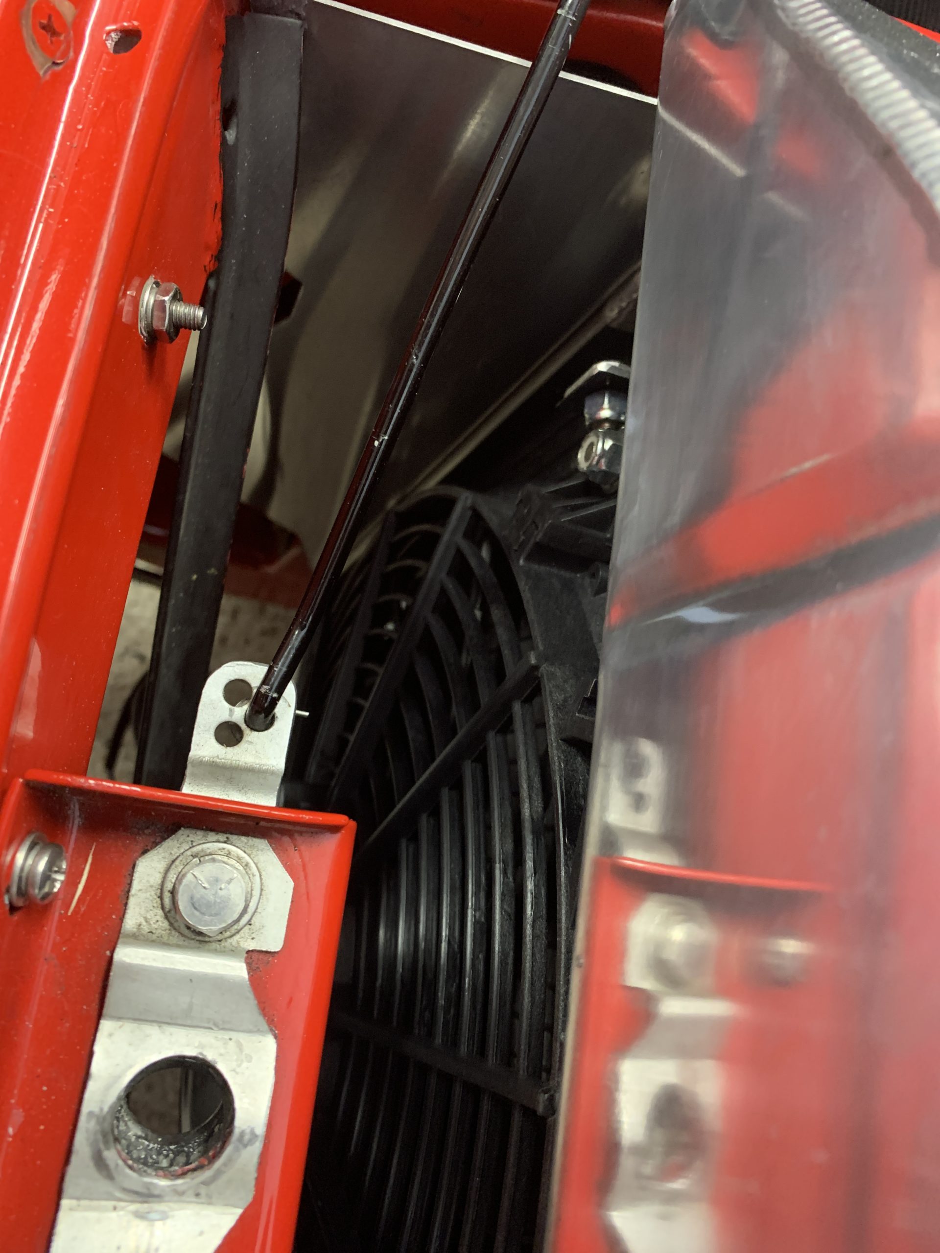
RH Radiator Baffle Installed
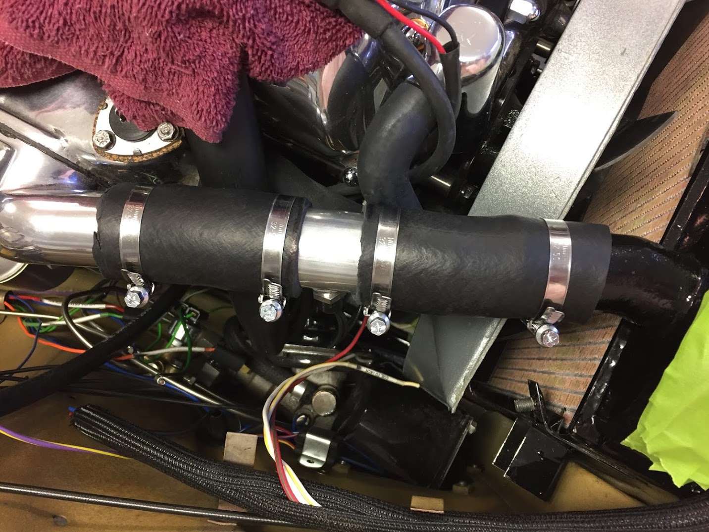
I then tightened the heater pipe hose clamp and the clamps for the upper radiator hose and the water pump hose. These need to be pretty tight to be effective and eliminate leaks!
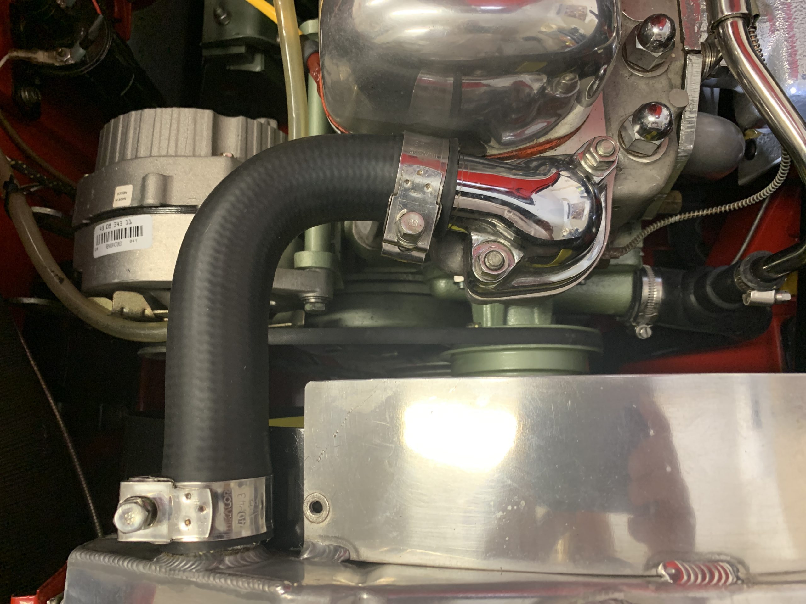
Hose Clamps Installed and Tightened
I then raised the car and from the underside reconnected the electric fan and tightened the four lower radiator mount bolts.
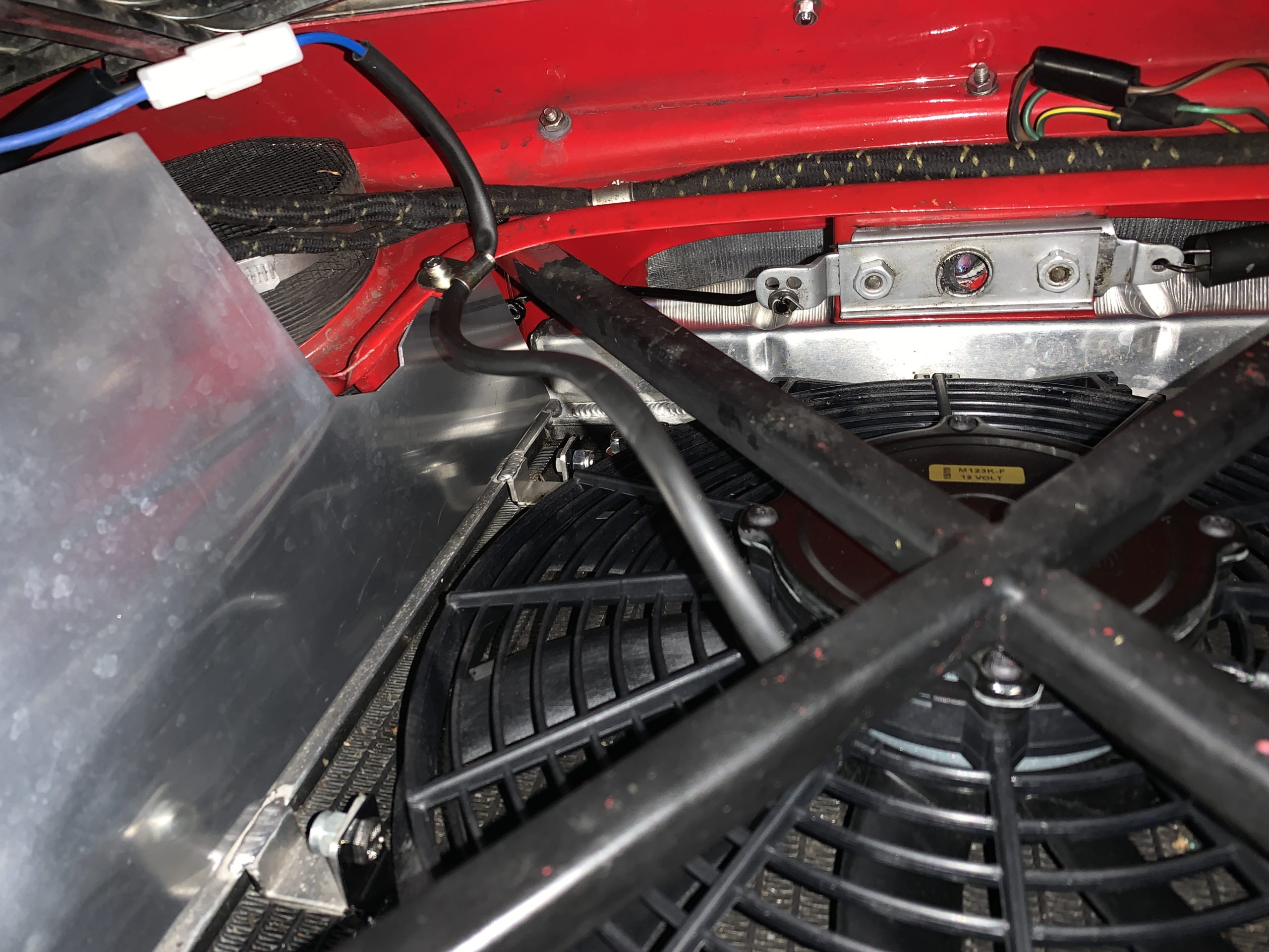
Electric Fan Wiring Reconnected
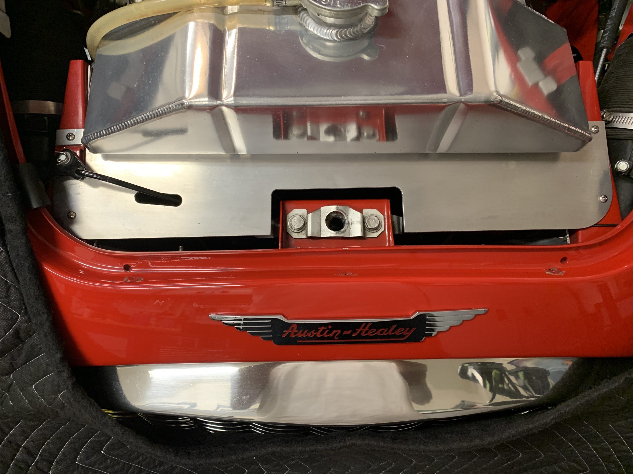
I then purchased some new tubing from the local hardware store for the overflow hose to the radiator neck, installed the aluminum cover panel, and reconnected the bonnet opening rod lever.
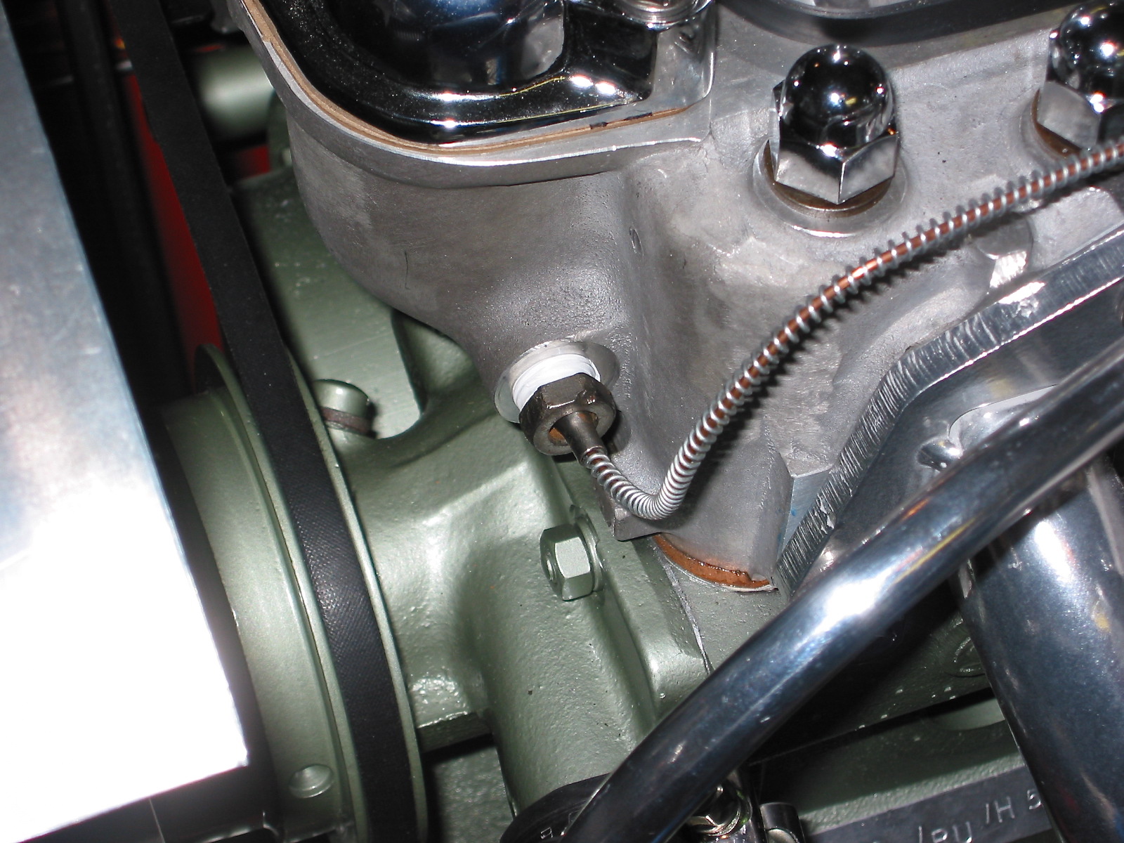
I then backed up a bit and loosened the two nuts and lock washers on the thermostat cover and lifted it away from the head. I removed the old thermostat and cleaned up the mating surface on the head and the cover to prepare for the new gasket.
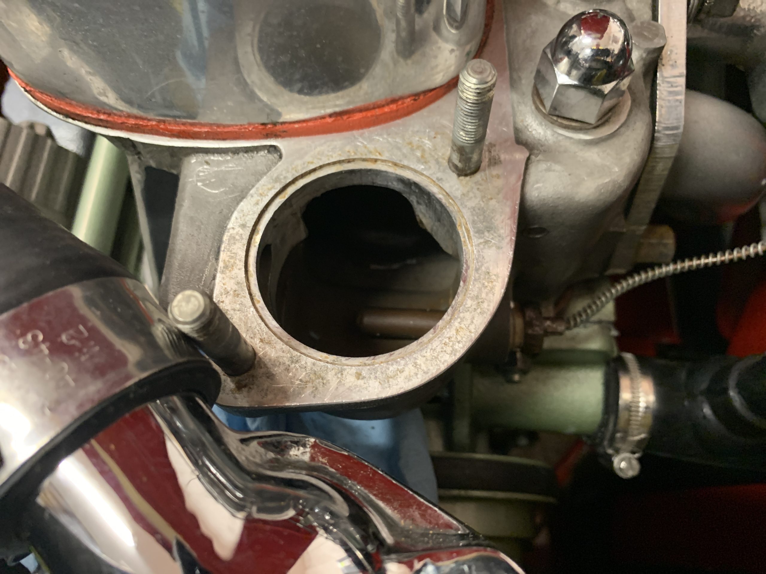
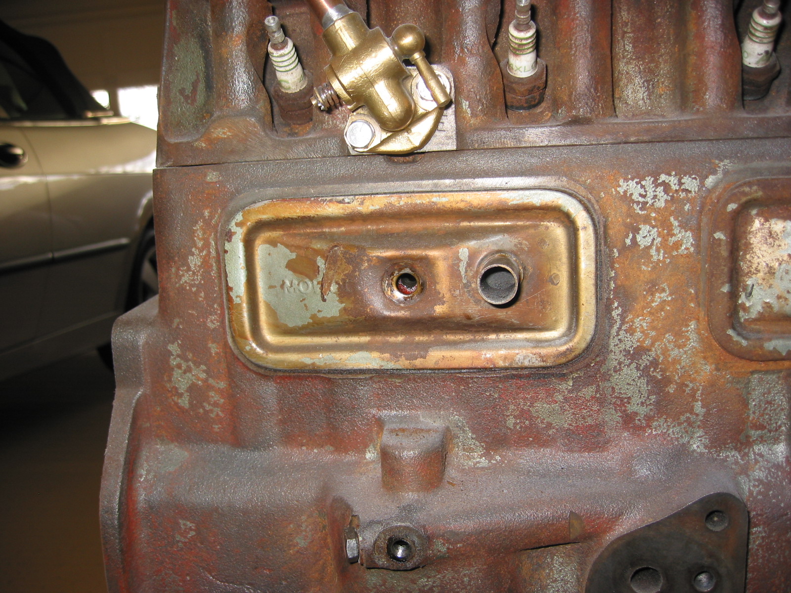
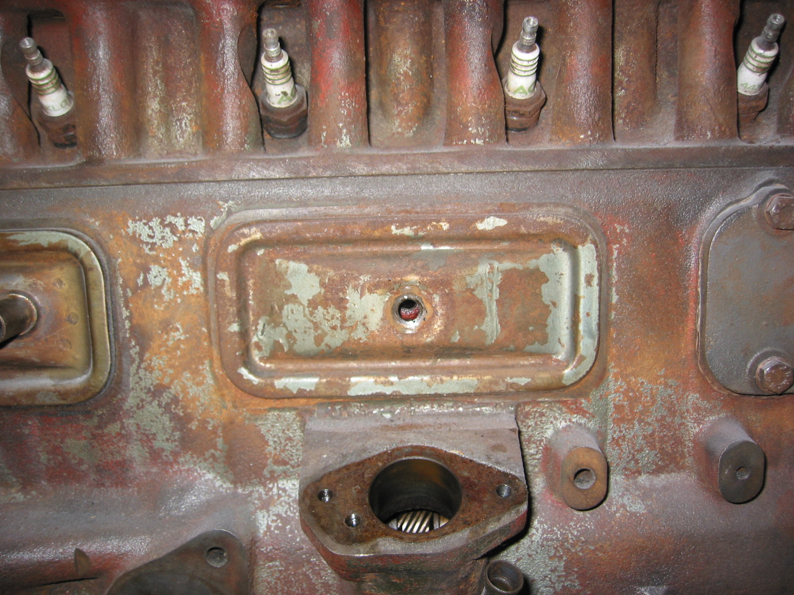
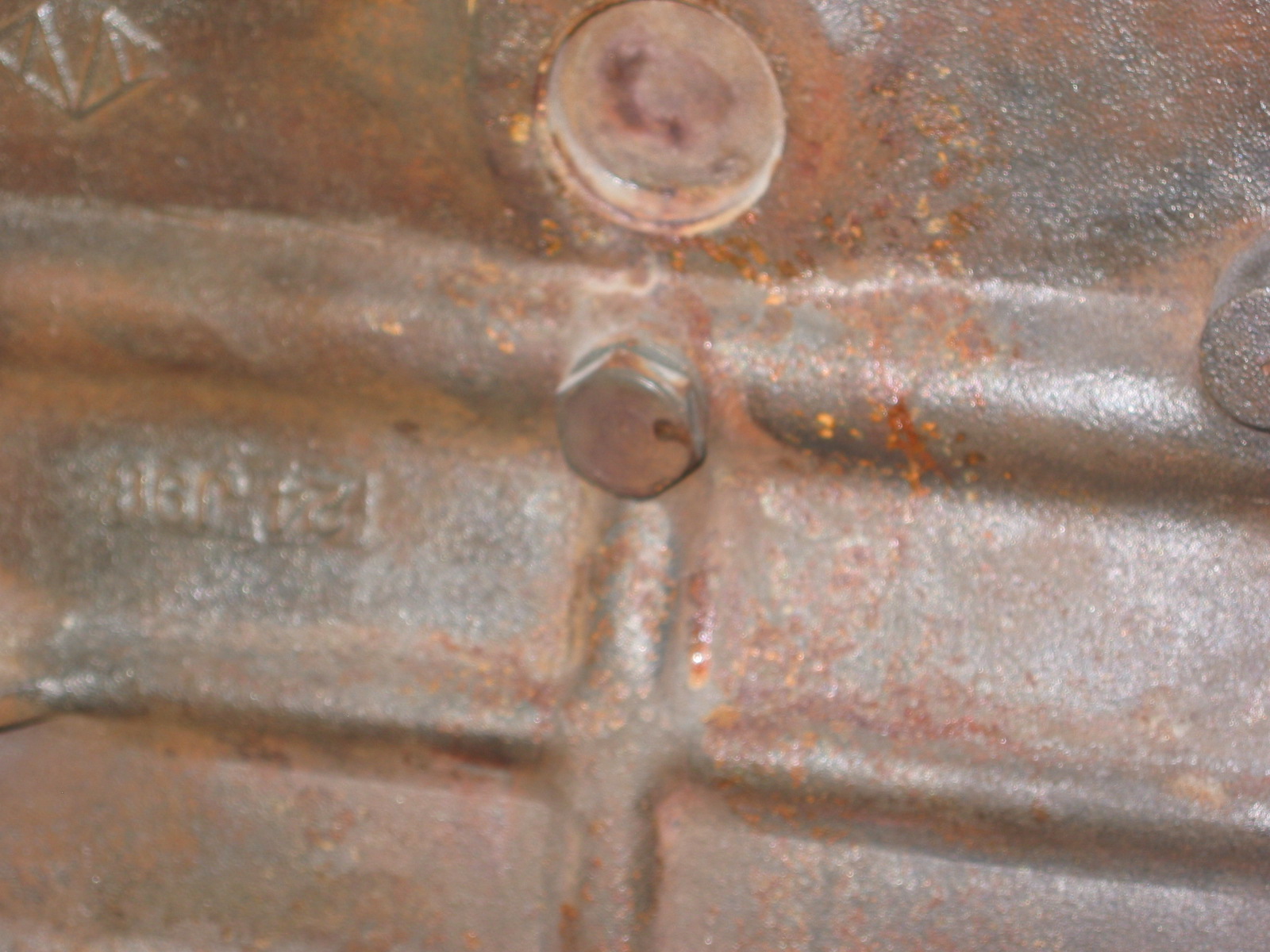
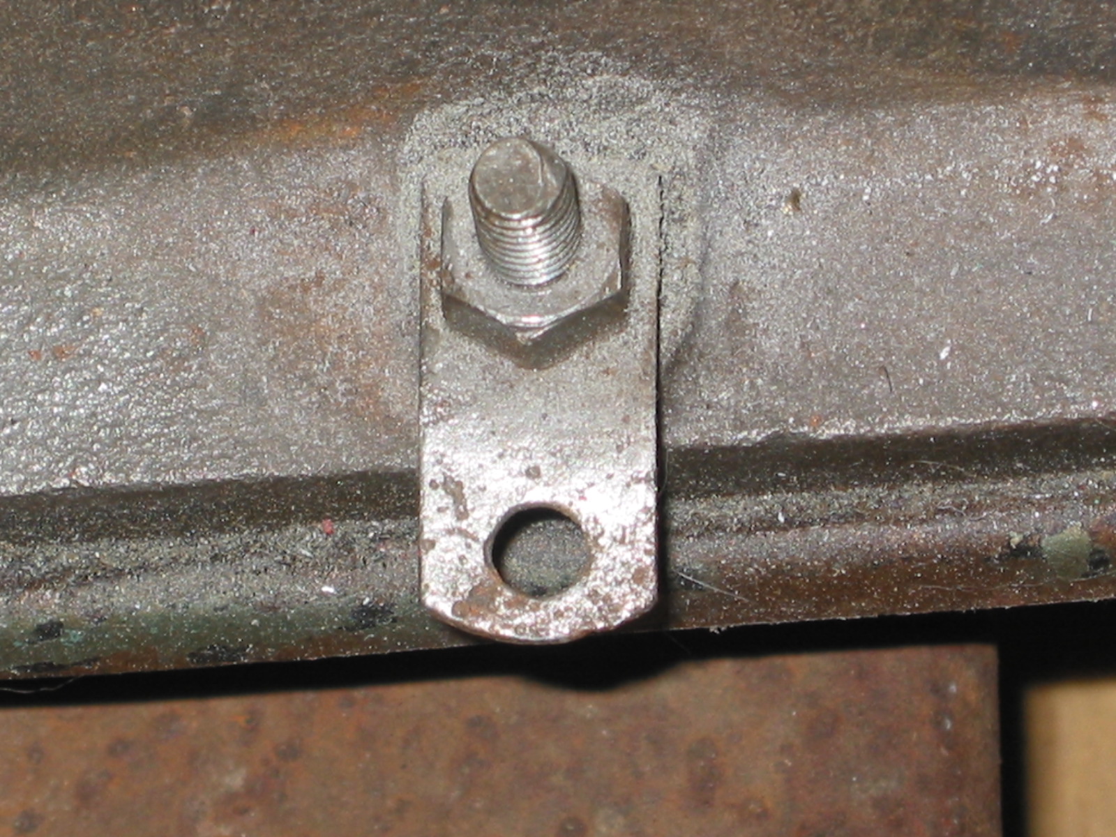
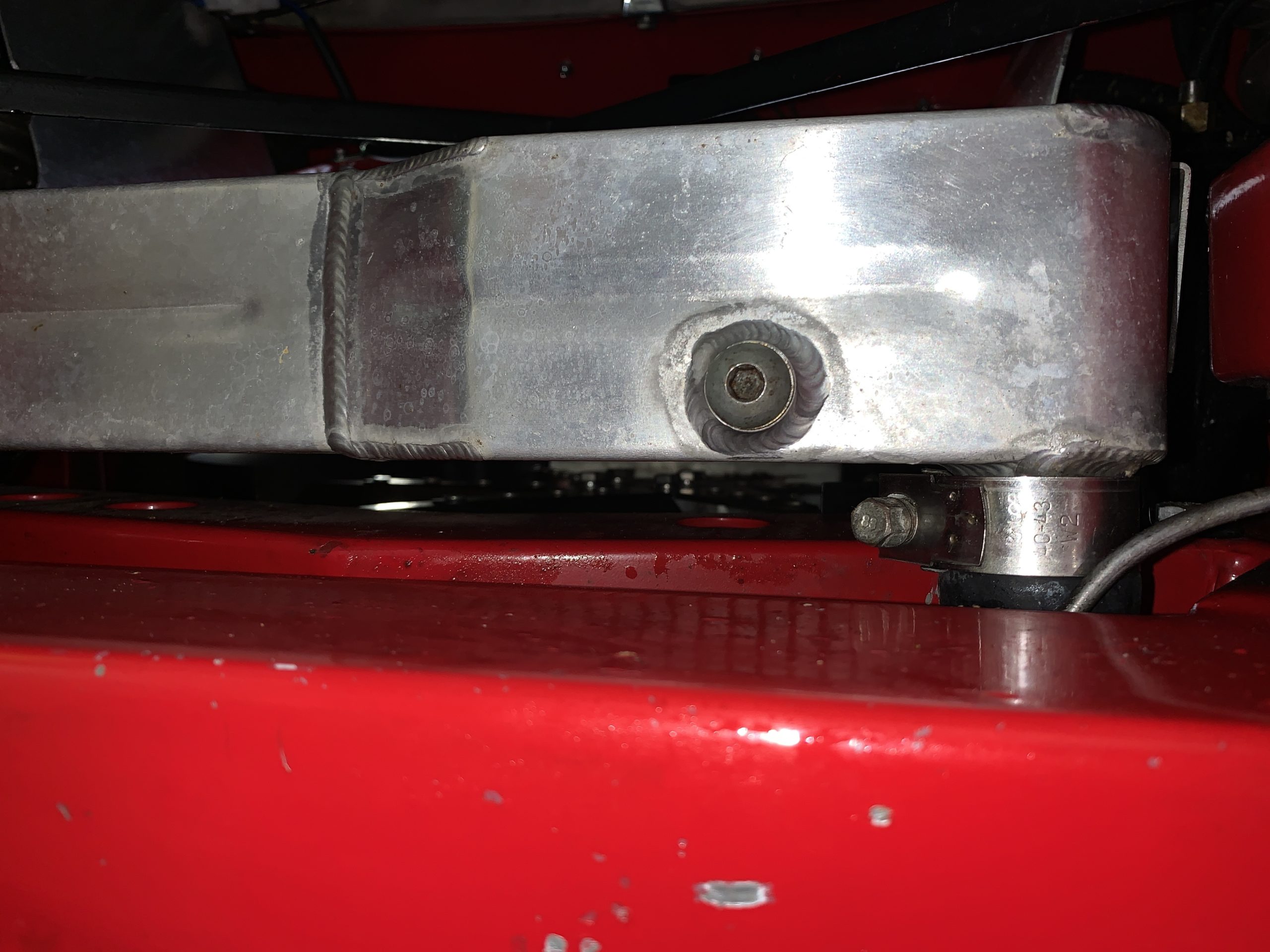
Thermostat seating in the cylinder head.
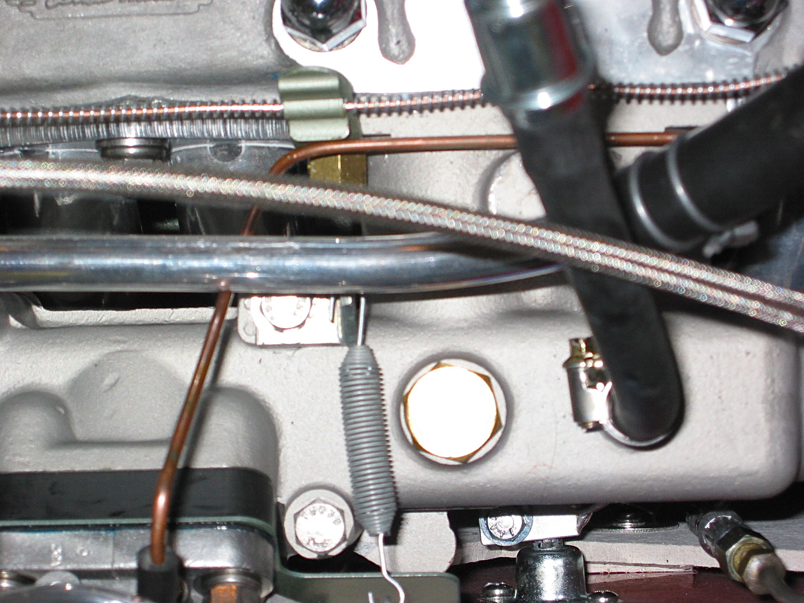
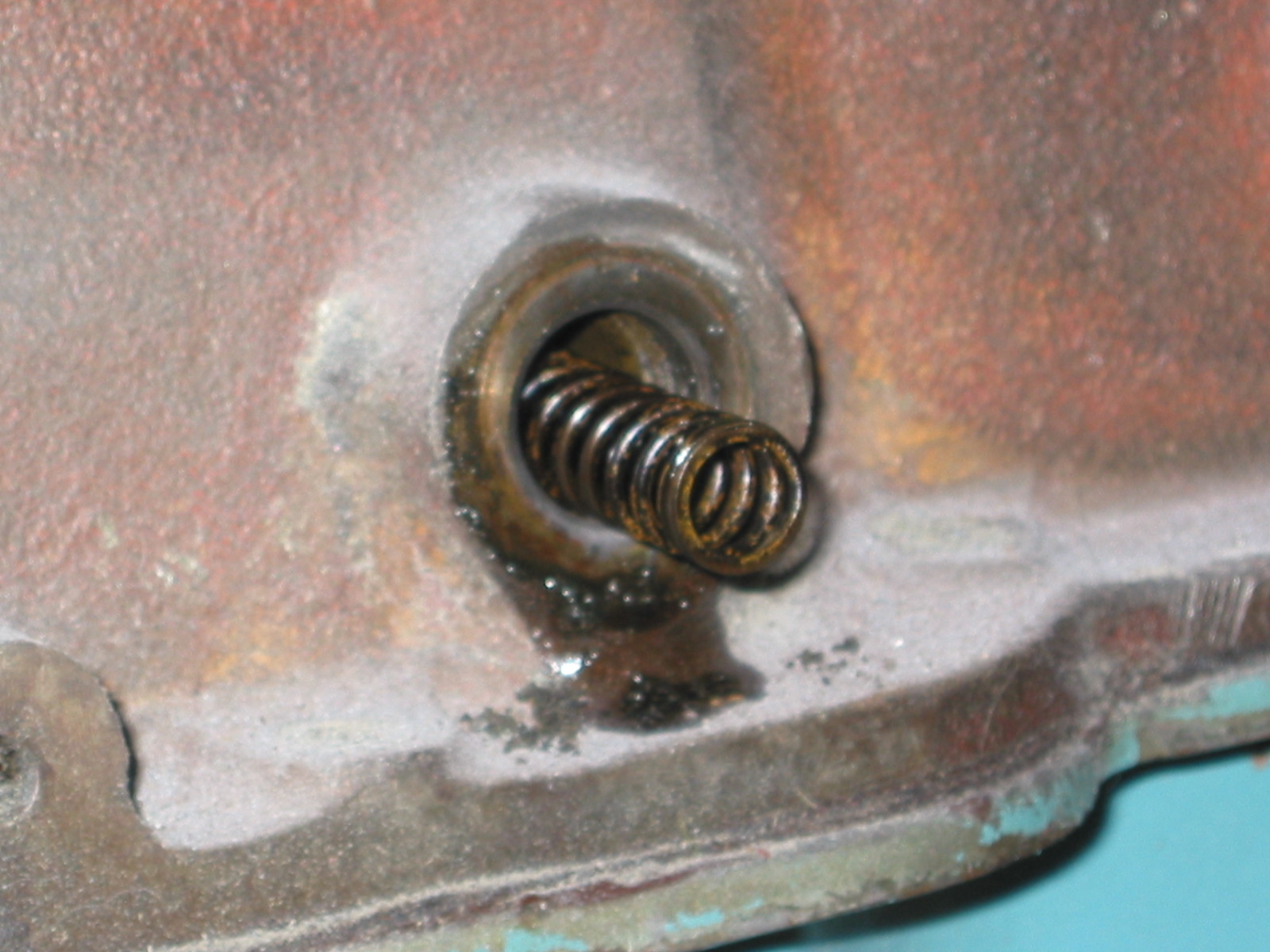
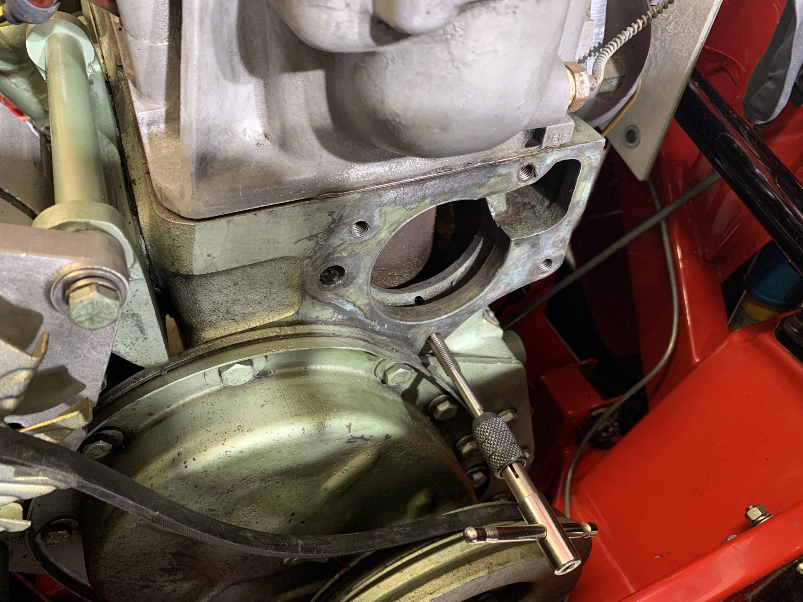
I decided to use a sleeved thermostat this time around to try to enhance cooling functionality. The following photo shows the hole in the cylinder head permitting recirculation of engine coolant to the engine. The sleeve of the thermostat blanks off the opening until the thermostat opens and coolant from the radiator is introduced to the system.
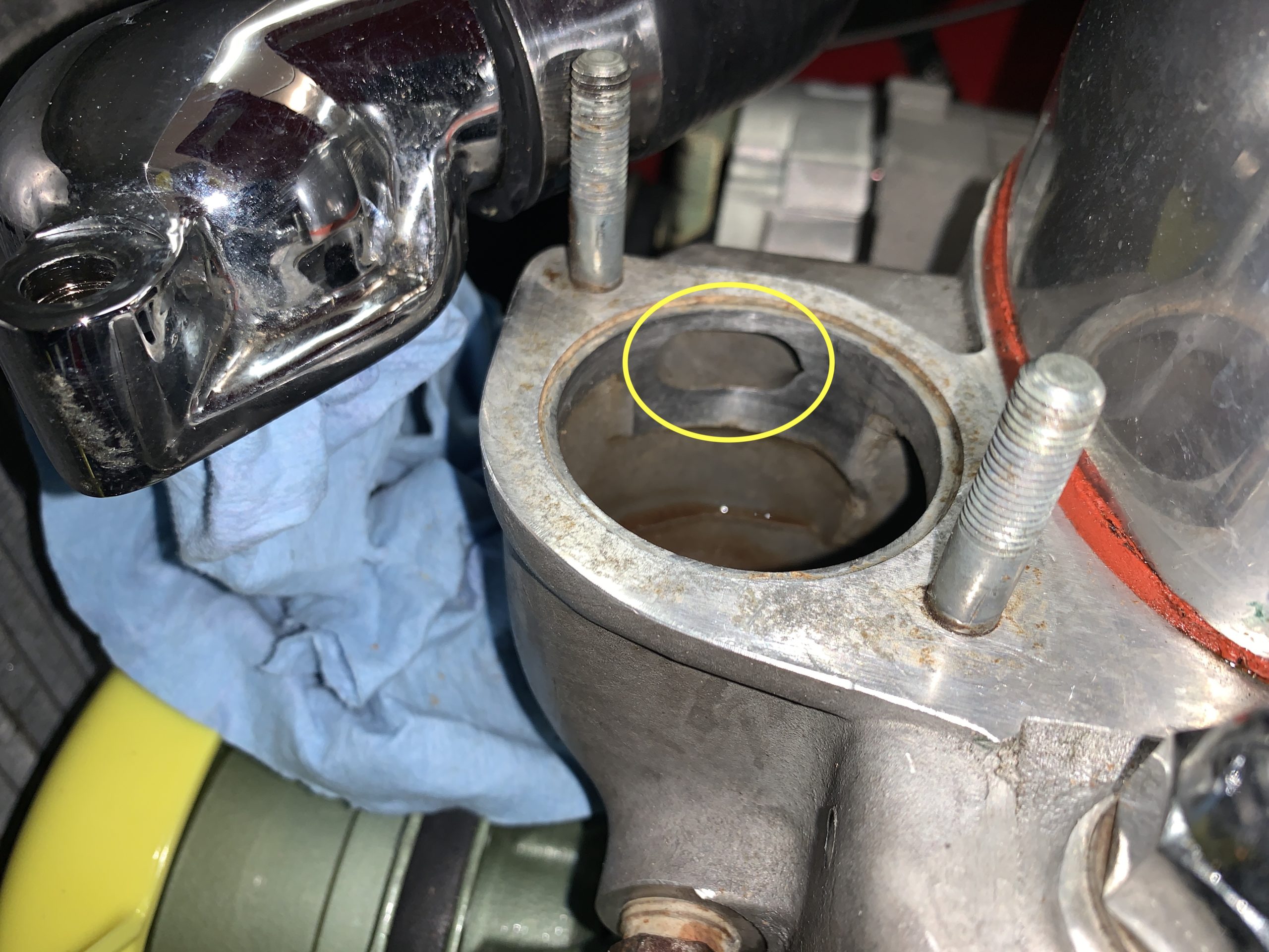
Coolant bypass opening circled
I again used Permatex Water Pump & Thermostat Housing RTV silicone on both surfaces of the gasket and installed the gasket and thermostat. I then tightened the two split washers and nuts and cleaned up around the edges where the sealant pushed out of the joint.
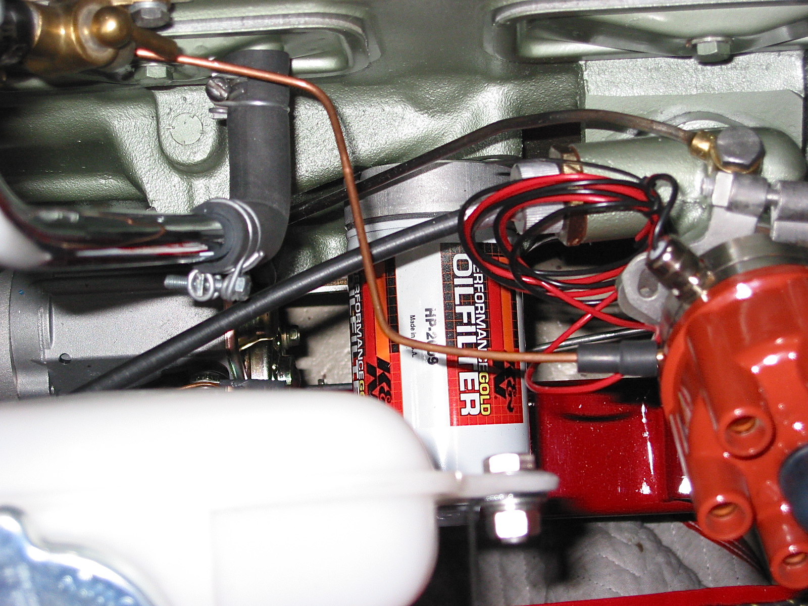
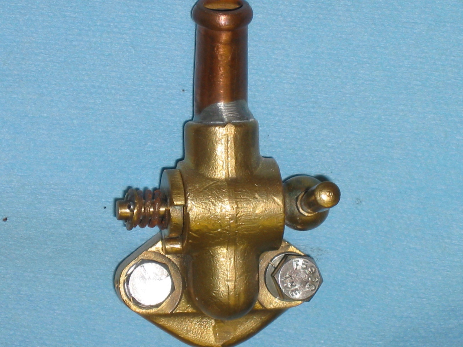
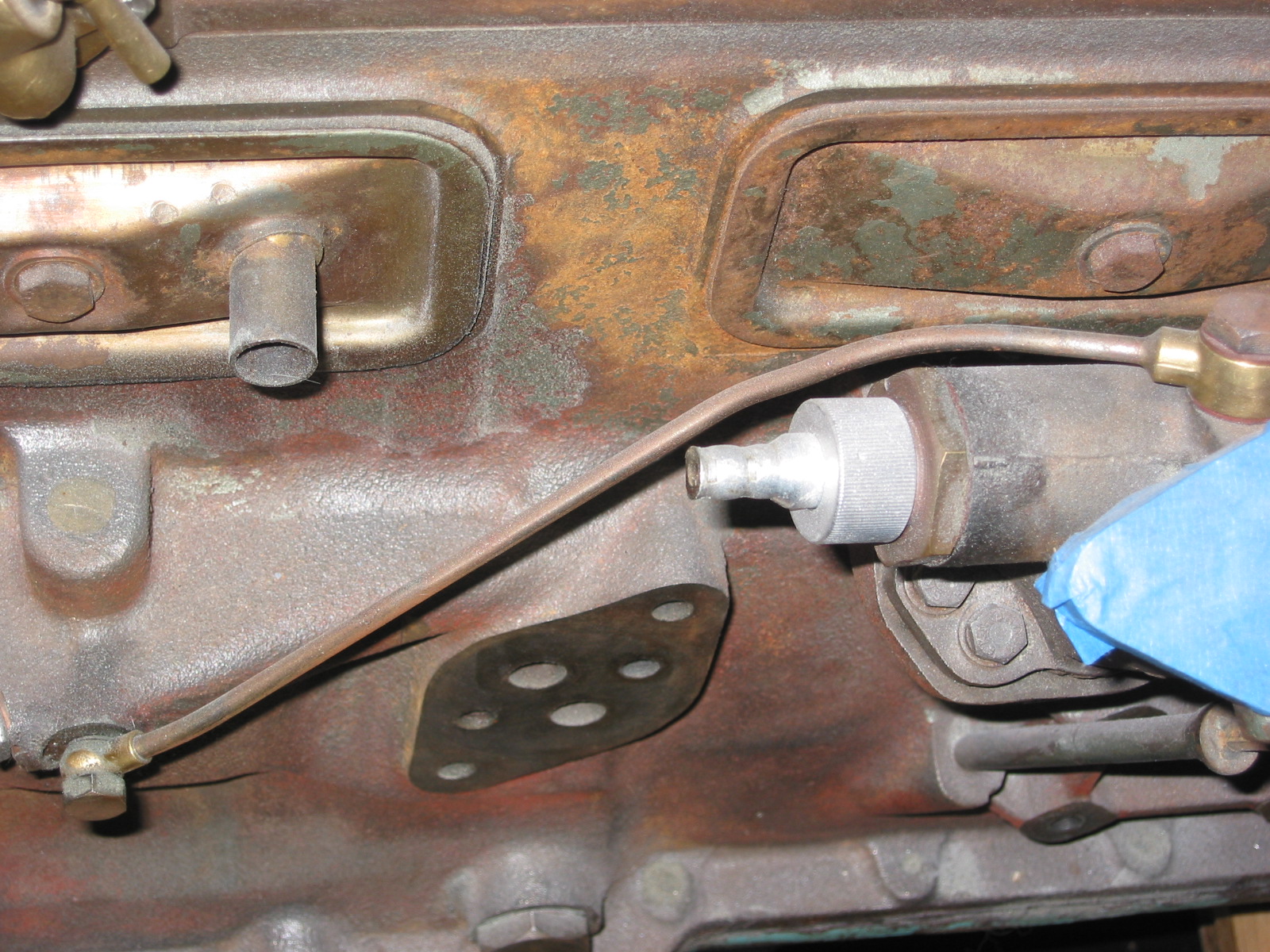
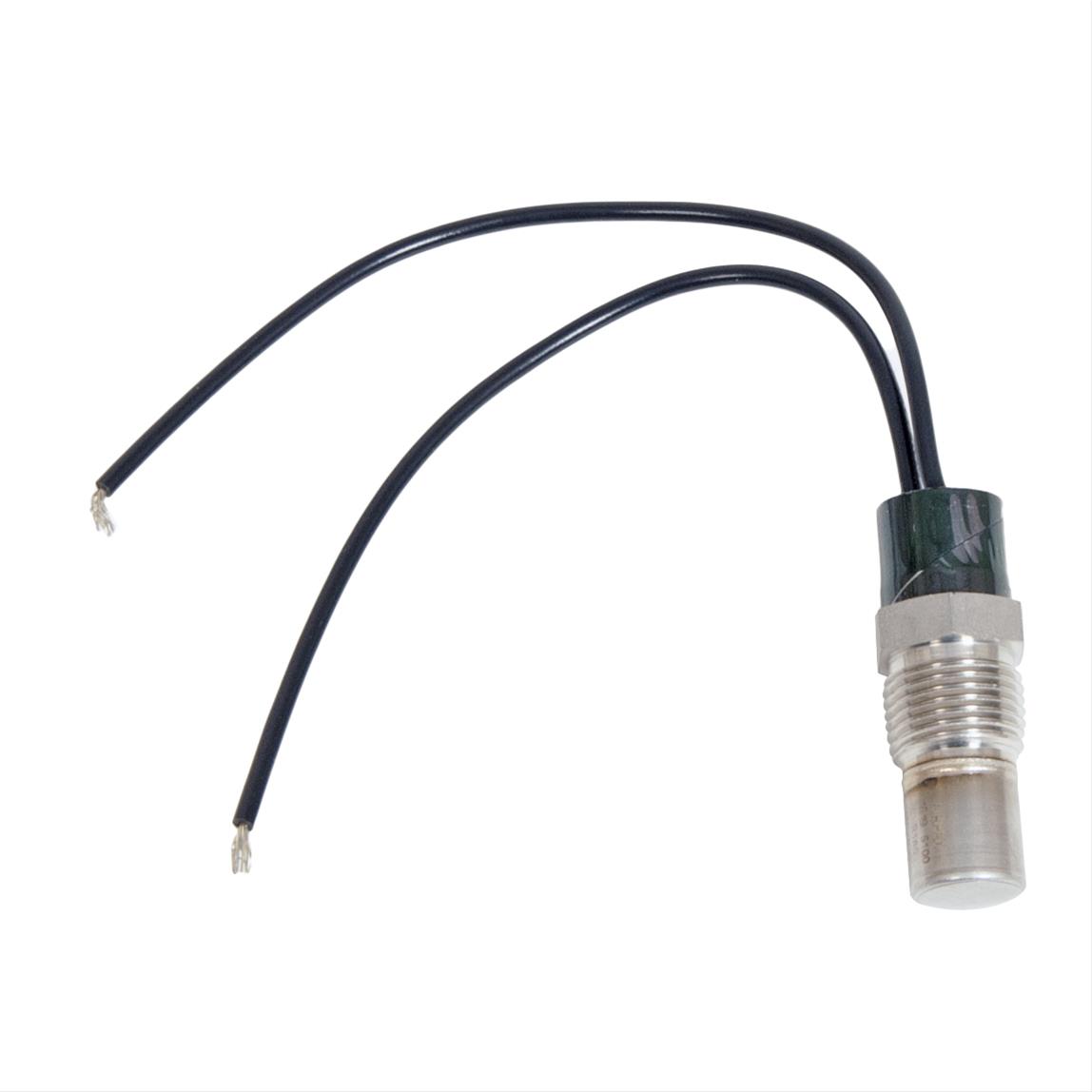
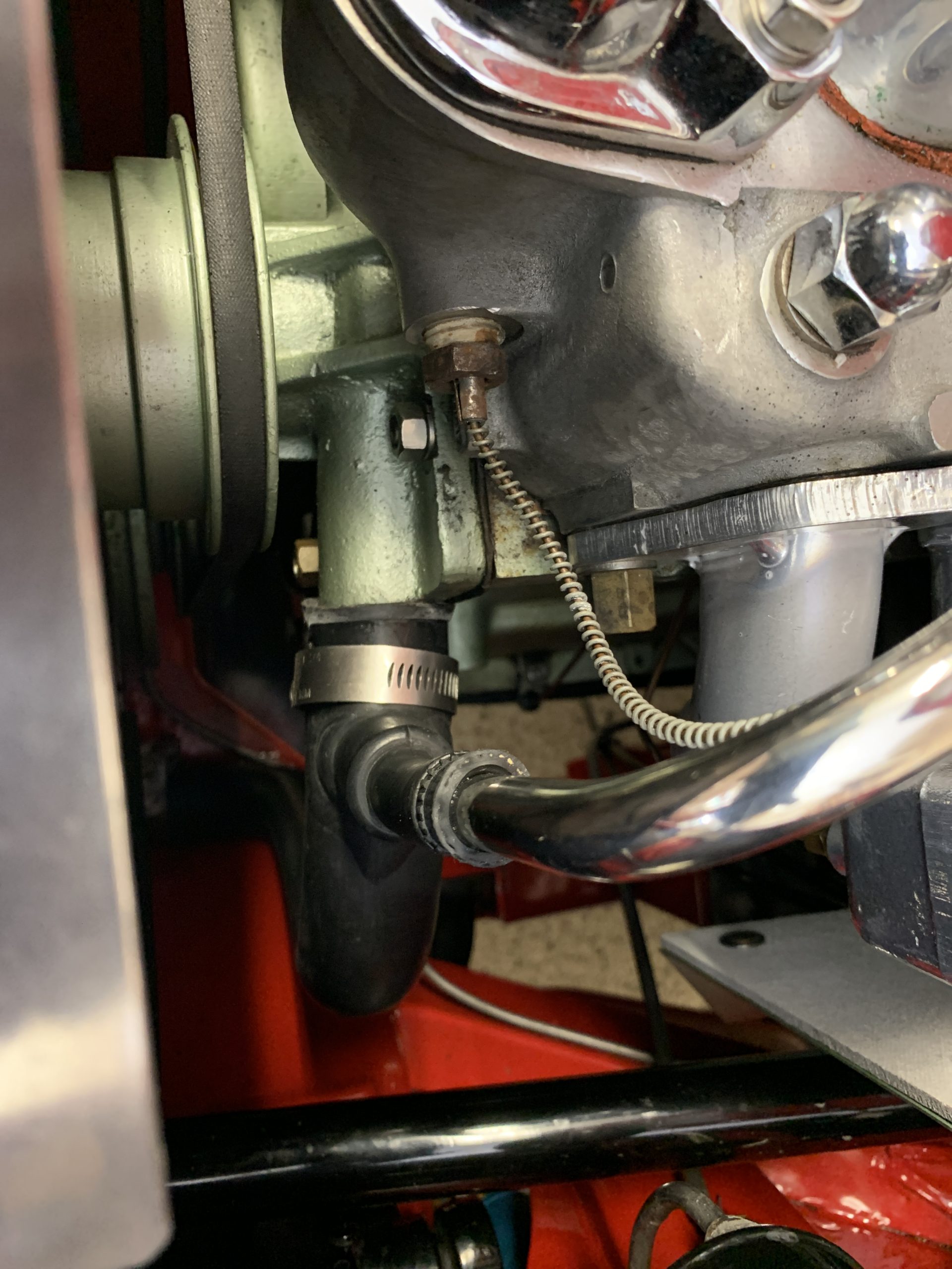
I decided while I was at it that I would check the accuracy of my dash fascia temperature gauge so I unscrewed the sensor from the head, freed the capillary tube from its two holders and put it in hot water and measured the temperature. While it didn’t exactly match the thermometer I was using in the hot water it was within a few degrees so I felt good about the accuracy of my gauge. I then put a little paint on the nut and reinstalled the sensor to the head using some yellow plumbers tape intended for oils.
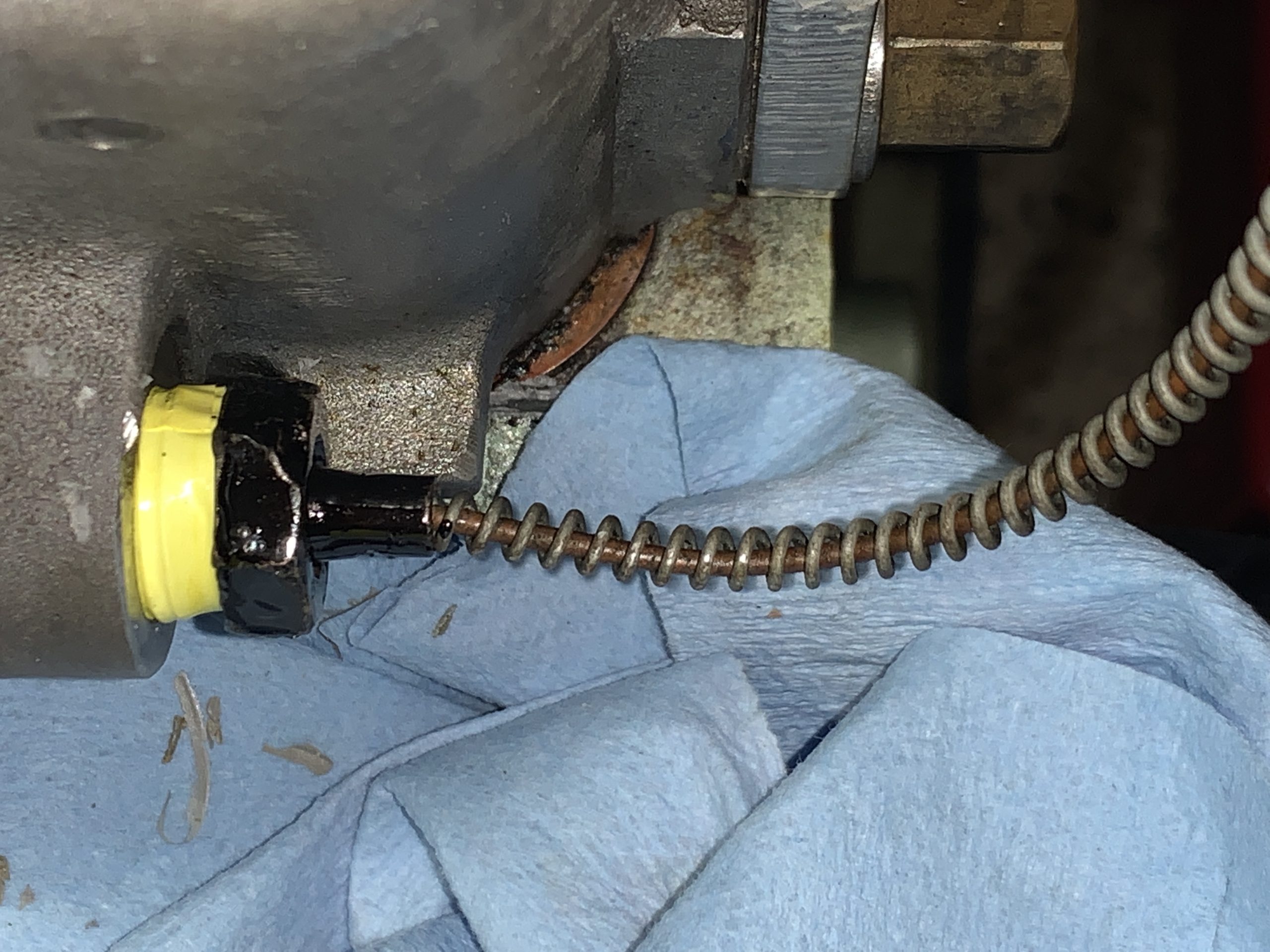
coolant temperature sender reinstalled
The sensor nut is hard to access. I used a flare wrench to do the job.
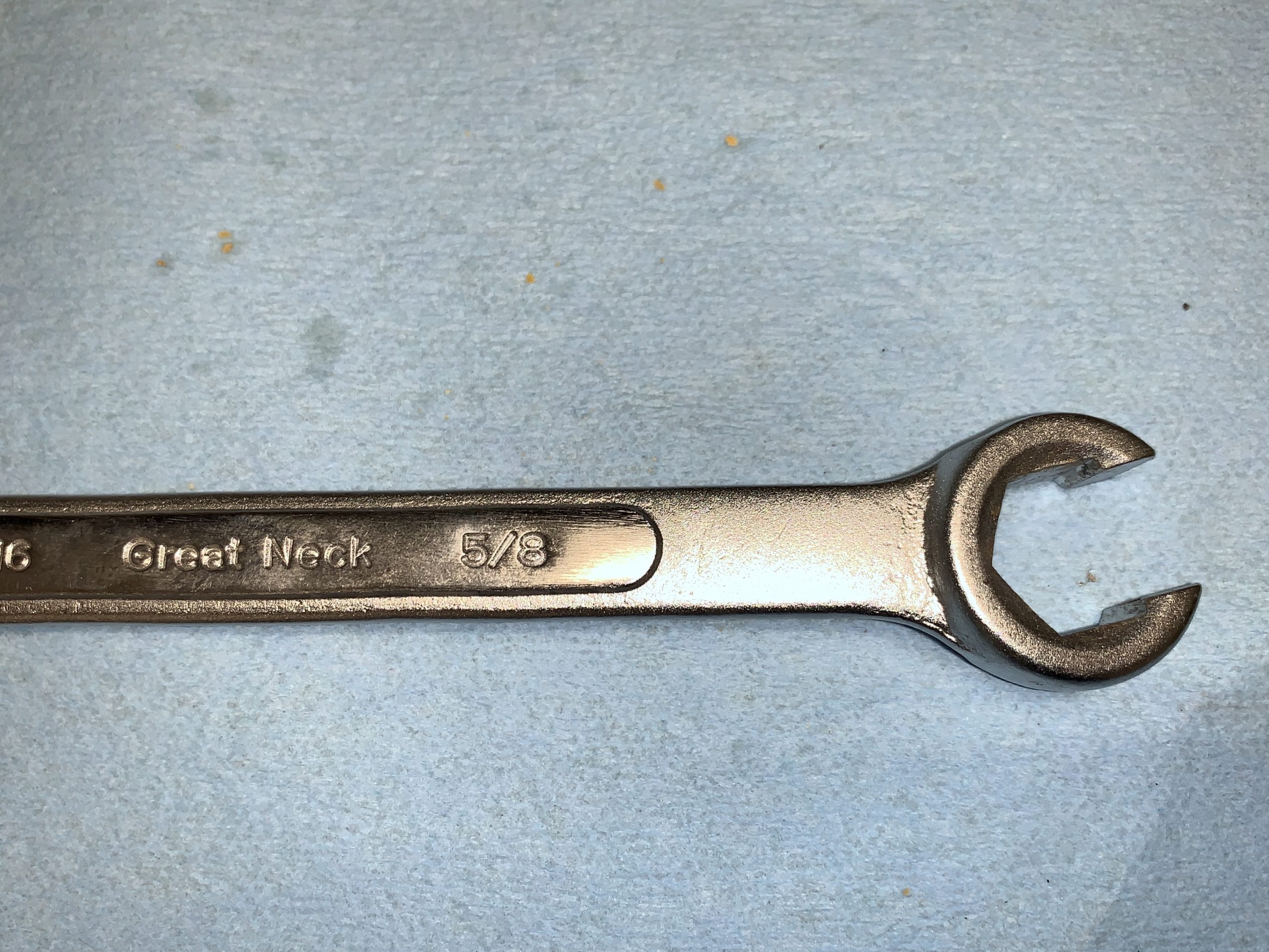
Flare Wrench 5/8″
After buttoning everything up, I took the car out for a short trip around the block and then inspected the engine bay to make sure that I had no coolant leaks. Having none, I then went out for about a thirty minute drive to “heat-soak” the engine. All systems were “go” with no problems and the engine getting no hotter than about 165 degrees.
Kent Lambert in Oregon located an original proper water pump (AEC206), pulley, key, lock washer and nut for me. It requires rebuilding so I have sent it to Michael Salter in Canada to have that job completed. I will then keep it as my spare water pump for the future! Thank you Kent and Michael.
Another ten-year renewal job checked off the list!